1
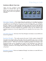
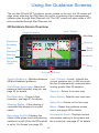
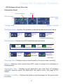
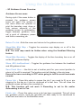
Patchwork Technology BlackBox 510 Operating Instructions For use with software version V:10.0.344 and above. PWdoc0010 v2.0 Contents page Product Overview 5 Using WebTrack with the BlackBox 7 8 9 10 10 11 11 13 14 Fitting Instructions 16 16 17 17 18 18 19 19 20 20 Unit Functions 21 Unit Setup 22 24 25 26 27 28 30 31 33 36 39 39 Creating a WebTrack Account Logging on to WebTrack Downloading and Installing WebSync Using „BlackBox Setup‟ for recording jobs Adding Details Enhancing Details (Farm Fields) Creating and Adding Form Items to Job Types (BB Pro users) Checking VRT Plans are available (VRT users) Transferring data to and from WebTrack via WebSync Mounting the Screen to vehicles windscreen Mounting the Tilt Correction Unit Transfer Kit (Optional) Attaching the External Antenna Connection Diagrams Main Unit Connecting VRT Cable Connecting an In Cab Printer Connecting an on/off Recording Switch Connecting a Weather Station Start Up menu BlackBox menu Setup menu Recording Details Recording Options Local Setting GPS Offset Ports Setup VRT Options Advanced Unlock page Starting a Job 40 41 41 41 42 44 Start New Job Farm/Field Auto Detect Resuming a paused guidance job Reloading a guidance line Start Planned Job Guidance Mode Overview Using the Guidance Screens 46 48 49 3D Guidance Screen Overview Guidance Screen menu Application Rate Options menu (Auto Shut Off only) Creating a Field Boundary Map Starting a Field Boundary Map Pausing and Closing boundary map during run Finishing and Printing a complete boundary map Future use for the maps Using Guidance and Field Recording Using first pass guidance (no Boundary) Using first pass guidance (with a Boundary) Using headland guidance Using a guidance line VRT Guidance Screen Overview Using Guidance and Field Recording (VRT Mode) Setting and using a guidance line Resetting the guidance line Setting points, Pausing and Finishing a Job Resuming a Paused Job Notes 50 50 51 51 51 52 52 53 54 55 57 58 58 58 59 59 59 Product Overview The BlackBox unit can be upgraded by unlocking various areas of the software allowing it to perform additional tasks. The basic unit will be supplied with the BlackBox software unlocked, please see the following for details on the different software versions:BlackBox Plus This software is used to record either basic job information against a job name or full Farm and Field tracking of jobs. This allows for a variety of uses depending on your needs. Within this software is a feature to tell the operator which field he is in once the field has been mapped and stored on the memory card. This is useful for operators who don‟t know the names of fields but know the location and the work to be done. Features: 3D Guidance Recording (Green Trace Recording) Field Area Measurement (Field Boundary Map) Headland Warning (see page 32) BlackBox Pro The Pro version adds two very useful features to the BlackBox Plus software: Notes (WebTrack required) – This allows the farm manager to add notes (form items) to a job type that the operator will then enter the relevant information when that job type is completed. For instance if the operator is Fertiliser Spreading, the system can be configured to ask for the Fertiliser Type or Product and the Amount of Fertiliser Applied in this field. These notes are created and added using WebTrack on the farm office PC. Planned jobs from Farm Management Software – This allows the uploading of Spraying Operations to be done with product information, safety details and is customised for the Farm Management software to select the correct Notes to be added to the end of the job. Once these jobs have been confirmed using the software, the data is returned to the Farm Management Software for storage. Compatibility list: Muddy Boots Pear Technology Farmade GateKeeper 5 Product Overview VRT This upgrade allows the unit to send application rate information using variable rate application maps to the controller attached to the implement. Adding Variable Rate to the Blackbox is simple and the compatibility list of controllers is extensive: Amazone Amatron+ and Amados+ / Bogballe 2003w, Uniq and Icon‟, / Raven 400, 600, 4000 / LH Agro 5000, 500, 6000 / Kuhn Quantron L, M, P, E / Kverneland Group / Passtronic / RDS Pro Series / Vaderstad / Dickey John Auto Shut Off With auto shut off setup on the unit, when driving into an area which has been worked (indicated by the green trace line on guidance screen), a signal will be sent to the controller to stop the implement working. After driving out of the worked area the unit will send a new signal to the controller to start the implement working again. N.B. Function not available on Amazone spreaders. 6 Using WebTrack with the BlackBox WebTrack is an internet based solution for the storage and viewing of data that has been recorded using the BlackBox unit. It is recommended that the recorded data is regularly transferred to the WebTrack account to ensure your records are kept up to date and secure. Creating a WebTrack account Go to the WebTrack home page by typing www.bbwebtrack.com in your internet browsers address bar. Beneath Create New Account left mouse click on Register New Account. To register for an account, left mouse click on Click Here to Sign Up. Enter your details in the boxes provided and once complete left mouse click on Create WebTrack Account N.B. Please ensure you use an active email address and it is typed correctly. 7 Using WebTrack with the BlackBox A confirmation screen will then appear. To return to the WebTrack home page left mouse click on Log in. Logging on to WebTrack Under the Existing Users heading enter your Username and Password, then left mouse click on Login. There are two options and as a first time user left mouse click on Click Here To Download WebSync to download and install the WebSync Tool (For details see page 9). Otherwise left mouse click on the Start Page button. You will be redirected to your WebTrack user area. 8 Using WebTrack with the BlackBox Downloading and Installing WebSync software N.B. WebSync is the essential tool to transfer data to and from the BlackBox unit via your WebTrack account. Fr om the W elc om e to WebTrack page, left mouse click on Click Here To Download WebSync. Follow the on screen instructions to download and install WebSync. Once WebSync has downloaded and installed, when prompted insert the BlackBox memory card. Left Click on Retry. The configuration screen will open for first time users to setup WebSync. Enter your WebTrack Username in the „User‟ box and select the unit measurement type required. When complete click OK. The main WebSync screen will open ready to transfer data, dis pla yin g the W ebTr ack username and the memory card location and type that data will transfer to / from. To reopen in the future go to the Windows Start Button, then All Programs, locate and open the Patchwork Technology folder, and left mouse click on PWWebSync. 9 Using WebTrack with the BlackBox Using ‘BlackBox Setup for recording jobs Before using the Blackbox for recording jobs, the Farm and Fields, Vehicles, Implements (switch type and width), Operators and Job types can all be preset in WebTrack. The Job types can be enhanced by adding form items. The form items will be listed on the Notes screen which opens after a job is finished, this prompts the operator to enter information about the job before completing it. For example the information required could be the weather conditions and/or the chemical used for the job. Setting up these details in WebTrack allows the operator to quickly and simply setup the job details by selecting the details from a list on the BlackBox unit (see „Unit Setup – Selection List‟ on page 22). N.B. To get the data to the BlackBox unit a WebSync must be performed, see „Transferring data to and from WebTrack via WebSync‟ on page 14. Adding Details Under BlackBox Setup on your WebTrack account, click Edit next to the item that you want to add the details to. Type in the name and any additional information that maybe required. Left click the Add button to add the details. 10 Using WebTrack with the BlackBox Enhancing Details (Farm Fields) Highlight the name in the list and click Edit. A new set of options will appear. In the Field Name box type in the details and click Add. To add another repeat the previous step. Once complete click Save. Creating and adding form items to Job Types (BB Pro users) Under BlackBox Setup on your WebTrack account, click Edit next to Single Notes. There are seventeen predefined form items, to add additional ones click Add. 11 Using WebTrack with the BlackBox ...creating and adding form items to Job Types (BB Pro users) Type in the name, select the input type and click Save. To add more form items follow the two previous steps. When complete click Job Types. Highlight the job in the list that Form Items are to be added to and click Edit. Click in check box next to „Use Form Items on this Job Type‟ The form items options will appear, left mouse click Add 12 Using WebTrack with the BlackBox Select form item using the drop down box and left mouse click in the boxes to select the required options. Click Save to add the form item. To add another form item click Add or click the Save Job Type button once complete For more details about the My Unit Setup section see the ‘WebTrack Overview’ user guide in the WebTrack help area. Checking VRT Plans are available (VRT users) When a precision farming contractor has completed variable rate plans of your fields, they can upload them directly to your WebTrack account in BBA, ShapeVRT or XML Format (please ask your precision farming contractor). Once uploaded the plans can be viewed in WebTrack as a list to check all the plans are on your account before transferring them to the BlackBox. N.B. To get the data to the BlackBox unit a WebSync must be performed, see „Transferring data to and from WebTrack via WebSync‟ on page 14. W h e n l o g g e d i n t o yo u r WebTrack account, under the Files section a select of file types are listed along with the amount of files for each type that are held on your account. To view a list of the files click on View next to the relevant file type. 13 Using WebTrack with the BlackBox ...Checking VRT Plans are available (BlackBox VRT users) From the list you can check that the relevant VRT files are on your WebTrack account before downloading to your BlackBox unit. N.B. Any files that you do not want on the BlackBox need to be moved to the archive or deleted. To archive or delete files, select the files by clicking in the box next to the file and then left mouse click Delete Selected Files to delete the files or Archive Selected Files to archive the files. Transferring data to and from WebTrack via WebSync When performing a Sync in WebSync the following data will be transferred:To WebTrack - Boundary Jobs, Guidance Recordings and Job Notes. From WebTrack – Details from My Unit Setup (including Job notes ). Maps and VRT plans that are held in the Files Section. Remove the memory card from the unit and insert into the PC. Open WebSync (If not installed please see page 9). From the Desktop of your Personal Computer, go to the Windows Start Button, then All Programs, locate and open the Patchwork Technology folder, and left mouse click on PWWebSync. 14 Using WebTrack with the BlackBox Please ensure the displayed Username is correct as the data will be transferred to / from the account held under that Username. If the Username is incorrect, left click on Configuration and enter the correct Username in the „User‟ box. If there are VRT plans no longer required on the memory card these can be cleared by clicking on Clear Card. Highlight the file types that are to be removed by clicking in boxes. Click OK to remove the files. When ready to begin the data transfer, left click on the Sync button. Once the transfer has completed left mouse click on the OK button to close the confirmation message. To view the data transferred from the BlackBox unit you need to login to your WebTrack account (see page 8). To use the data transferred from WebTrack, reinsert the memory card into the BlackBox unit and power up the unit. 15 Fitting Instructions Mounting the Screen to vehicle windscreen N.B. Supplied suction mount and ram arm my differ from the image below. Ensure the area on the windscreen where the suction mount will be attached is clean, and then push it on the windscreen turning the lever clockwise to lock it in place. Turn Lever The ram ball and suction mount are then connected together using the supplied “Ram Arm”. This allows for multi-positional flexibility and is simply tightened with the thumb screw. Tighten Screw Warranty Void if suction mount fails !! - Its is advised that the suction mount is removed from the windscreen when the unit is not in operation and reattached on a day to day basis. For a more permanent fixing please detach the ram ball from the suction mount and secure down in the vehicle. Mounting the Tilt Correction Unit Mount the unit securely on to a flat surface within the vehicle with the arrow on the label pointing to the front of the cab. To Front 16 Fitting Instructions Transfer Kit (optional) If using a Transfer Kit (optional), firstly mount the bottom plate on a flat surface. Secure Mount Secure the unit to the top plate using the supplied screws. Line up the top plate with the unit attached and tighten the fixtures by hand. Tighten Fixtures Line up Attaching the External Antenna The BlackBox unit is supplied with either a Patch or Helix antenna, both types are magnetised ready to attach to a metal surface. Attach the antenna to the highest point of the vehicle and as close as possible width ways to the centre. A round metal plate has been supplied for vehicle roofs that are not made of metal. To fit, first clean a small area and ensure it is dry, then remove the plastic covers from the self adhesive strips on the metal plate and stick to the vehicle roof. Patch Antenna Helix Antenna Back Front Metal mount plate The antenna will now stick to this plate and be held safely on the roof. N.B. In many cases running the cable in through a window or door is acceptable, please make sure that there is enough of a gap in the rubber to allow this, otherwise the cable could be damaged and with no signal from the antenna the BlackBox will not function correctly. 17 Fitting Instructions Connection Diagrams Main Unit Guidance Screen Screen Connector SD Card For recording job data. Must be inserted for the unit to operate. Tilt Correction Unit Magnetic Antenna 12v DC Plug To cigarette lighter socket on vehicle. Warning - Please disconnect the unit from the power supply, if you need to jump start your vehicle. 18 Fitting Instructions ...Connection Diagrams Connecting VRT Cable Tilt Correction Unit Controller To port on Controller To serial port 2 Supplied Cable The BlackBox will need to be configured to work correctly with the controller, for details see VRT Options menu on page 36. Connecting an In Cab Printer In Cab Printer Tilt Correction Unit To serial port 2 To port on Printer Supplied Cable The BlackBox may need to be configured to work correctly with the In Cab Printer, for details see Ports Setup menu on page 33. 19 Fitting Instructions ...Connection Diagrams Connecting an on/off Recording Switch Tilt Correction Unit Rocker Switch To rocker switch or 12v feed. The BlackBox will need to be configured to work correctly with the switch, for details see Ports Setup menu „On/Off‟ on page 33. Connecting a Weather Station Weather Station Tilt Correction Unit To serial port 2 To port on Weather Station Supplied Cable The BlackBox will need to be configured to work correctly with the Weather Station, for details see Recording Options menu „Weather Station‟ on page 28. 20 Unit Functions Tilt Correction Unit Power On/Off button – This turns the power to the tilt correction unit on/off. The power must be on to provide power to the screen. GPS On/Off button - To use the built in GPS this needs to be set to On, if using an external GPS source via serial port 1 set to Off. Tilt Reset button – When setting up the Tilt Compensator in Ports Setup (see page 33 for details) use this button to reset tilt angles. Power On/Off GPS On/Off Tilt Reset Touch Screen Screen Power On/Off button – This turns the screen on and off, providing the tilt correction unit is switched on. Brightness button – Press this button to scroll through different levels of brightness for the display screen Power On/Off Brightness Touch Screen – The unit uses an LCD Touch Screen which allows the user to interact with the BlackBox software. Use the Touch Screen by pressing and applying some pressure to the area of the screen where the required button or option is. 21 Unit Setup When using the BlackBox from time to time there will be a requirement to enter information or select an option from a list to continue. This will occur in the menus or when starting a job and there are four different input methods:Selection list Some of the selection lists are predefined in the BlackBox, others can be setup by the user on WebTrack in the My Units Setup section (see page 10 for details). The selection lists that can be setup by the user have a *NEW* option which if selected will open the text entry screen so the information can be entered manually (see „Text Entry‟ below for more details). To use the Selection List firstly highlight the option in the list by pressing on it or use the Up and Down buttons. Once the desired option is highlighted set it by pressing OK. To exit the selection screen without making changes press Cancel. Text Entry This input screen will appear if the information that is required is text that needs to be typed in manually. To use the text entry screen, press the letters or numbers on the screen to enter the details. Once complete press on OK to add the details and close the text entry screen. To exit the text entry screen without adding any details press on Cancel. 22 Unit Setup Numerical Entry This input screen will appear if the information that is required is a number that needs to be entered manually. To use the numerical entry screen, press the numbers on the screen to enter the figure. Once complete press on OK to add the figure and close the numerical entry screen. To exit the numerical entry screen without adding a figure, press on Cancel. Option Box The option box will appear if the required information is a simple Yes/No selection. 23 Unit Setup Start Up menu Once the unit has been installed in the vehicle and all the wired connections secured, press the power button on the connection box and ensure the LED light is lit. Next press the power button on the screen and wait for the system to load up to the Start Up Menu. The Start Up menu is used to load and update the Black Box software. This is also the safe screen for powering down the unit. Start BlackBox - Accesses the BlackBox program menu (for more details see BlackBox Menu on page 25). Start BlackBox DR - Not applicable Start Field Note - Not applicable Upgrade - Initiates and installs any upgrades for the BlackBox 510 that are stored on the memory stick. Upgrades are available from under the Support Services section on the Patchwork website www.patchwork.co.uk Sync - Used to transfer data to and from WebTrack via a modem connection. 24 Unit Setup BlackBox menu The BlackBox menu is the main menu for setting up and accessing the different job modes of the BlackBox software. Status Screen Start New Job - Start a guidance job or new field boundary map (for more details see „Starting a Job > Start New Job‟ on page 40). Start Planned Job - Start a VRT plan or a plan created in a farm management software package (for more details see „Starting a Job > Start Planned Job‟ on page 42). Setup - Goes to the setup menu for the unit. Before starting a job it is important that the unit is setup for your requirements (for details see Setup Menu on page 26). Shutdown - Will shutdown the software and return to the Start Up menu where it is safe to power down the screen when it is no longer required. An option box will appear with two options, Yes to shutdown the software and No to keep the unit running. Status Screen - Pressing in the outlined area opens the status area, where the GPS and Steering status can be checked. Press OK to leave the screen. 25 Unit Setup Setup The Setup menu is used to setup the hardware and software for use within the job modes and it is vital that the settings are setup correctly for the unit to function as you require. Recording Details - Sets the details that will be recorded against the job for record keeping and also the implement working width which is important to accurately set the tracks when using the unit for guidance (See page 27 for more details). Local Setting - This option is used to set your preferences based on your location in the world (See page 30 for more details). GPS Offset - Adjusts the distance the actual work is taking place away from the antenna to improve guidance accuracy. The headland warning feature is also set under this option (See page 31 for more details). Ports Setup - Used to setup the serial ports on the Tilt Correction Unit if using an external GPS source (or as an external GPS source), Weather Station or In Cab Printer. The Terrain Compensator reset, Demo Mode and the green trace recording On/Off method is also set under this option (See page 33 for more details). VRT Options - Accesses the options for setting up data communications between the unit and a controller for Variable Rate Application and/or Auto Shut off (See page 36 for more details). Save/Load Profiles - Opens the area to save or load profiles created for use with the steering and boom section add on hardware (see supplied instructions for details). Advanced - Accesses the menu to unlock software modules (See page 39) and setup the steering and boom section add on hardware (see supplied instructions for details). Finished - Returns back to the BlackBox menu. 26 Unit Setup Recording Details All the details that are entered in this area will be added to the job recording and is displayed within the information area of a job report when viewed in WebTrack. Vehicle - The name of the vehicle that is being used for the job. Implement - The name of the implement that is being used for the job. If setup in WebTrack the width and recording On/Off method (found under Ports Setup) will be set. Job Type - Enter the name of the job operation that is being performed. If the Job Type selected has form items added to it in WebTrack (see page 11 for details on setting up Job Types), when the job is finished the operator will be prompted to fill in information related to the form items (see page 59 for details on finishing a job with notes). Operator - The name of the operator that is performing the job. Width - Sets the working width of the implement, this is vital to achieve the correct distance between the guidance lines. The width will be set automatically if an implement that has been setup in WebTrack has been selected in the Implement option. Recording Options - These options are used to setup how and/or whether the trace, farm details and weather station information is recorded (See page 28 for more details). Finished - Return to the setup menu. 27 Unit Setup ...Recording Details Recording Options The settings entered in this menu alter how data is recorded on the BlackBox, this includes the green trace recording and weather station information (if fitted). Recording - This option is used to turn job recording on and off. N.B. If recording is set to ‘No’ the pause job function will not be available and the unit will not save any job data when a job is finished. Autonaming - Sets autonaming on or off. Autonaming is used if the user does not want to input a farm and field name when starting a new job, if set to „Yes‟ an automatic job name will be created. N.B. Only use this option if you do not plan on keeping accurate records, pause jobs, reload guidance lines or use field boundary information. Minimum Speed - Sets the minimum speed that the trace will record at (i.e. if moving slower than the set speed the trace will not record). Minimum Angle - Sets the number of degrees that the heading can change since the previous green trace location point before a new location point is set. Maximum Distance - Sets the maximum distance that can be travelled in a straight line before a green trace location point is automatically set. Note if the minimum angle setting is met or exceeded a point will be automatically set. Weather Station - Opens the menu where the weather station recording options can be adjusted. See page 29 for Weather Station Recording Options menu. Finished - Returns to the Setup Menu. Important: Decreasing the values of the minimum angle or maximum distance will result in more location points being created, which can effect the performance of the unit. 28 Unit Setup ...Recording Details > Recording Options Weather Station Recording Options The options in this menu are used to select the weather details that will be obtained from a vehicle mountable weather station and automatically saved to the job when complete (BlackBox Pro required). The weather station needs to be connected via the serial port (see connection diagram on page 20) . Weather Station On - Sets the weather station recording On or Off. All other options are dependent on the Weather Station On being set to „Yes‟. Temperature - Turns temperature recording On or Off. Wind Dir - Turns wind direction recording On or Off. Wind Speed - Turns wind speed recording On or Off. Units - Changes the units which the wind speed is recorded in. Humidity - Turns humidity recording On or Off. Air Pressure -Turns air pressure recording On or Off. Test - Press to ensure the information is being received from the weather station. The test screen will open displaying the information that has been set, once the test is complete press OK to return to the weather station menu. If unsuccessful the serial port speed may need to be adjusted (see Ports Setup on page 33) Finished - Returns to the Recording Options menu. 29 Unit Setup Local Setting The options in this menu are used to set your locality in the world, unit measurements, language and the time difference (based on GMT). Country - To select which country you are in. Units - Sets the unit measurement type (i.e. Miles or Kilometres); this will affect the menu areas and guidance screen where a measurement is required or displayed. Language - To select the language that you want the menus to be displayed in. Time Offset - To adjust the time difference for your location based on Greenwich Mean Time. This can also be used for Day Light Savings time. Finished - Returns to the Setup Menu. 30 Unit Setup GPS Offset The options in this menu are used to offset the GPS position in relation to the position of the antenna (the unit measurement will depend on the units setup in Local Setting, see page 30 for details) and access the Headland Warning Options. Offset Left / Right - Sets the offset distance from the antenna for left or right. Note a negative number must be entered if setting to the left. Offset Front / Back - Sets the offset distance from the antenna for front or back. Note a negative number must be entered if setting to the front. No Offset With Offset Recording takes place from the antenna position. Recording takes place from the offset position. Offset to Back Antenna position Offset to Back and Right Offset position Offset Example Headland Warning Options - Opens the Headland Warning Options menu. See page 32 for the Headland Warning Options. Finished - Returns to the Setup Menu. 31 Unit Setup ...GPS Offset Headland Warning Options The options in this menu are used to setup the Headland Warning feature. The feature guides you to a set point off the field boundary which we call the „headland edge‟. This counts down the distance as you approach it, so when the headland edge is reached the distance is zero and the operator knows when to stop or start the implement working. N.B. A field boundary map needs to be created for the field and the mini map in the guidance screen hidden for this function to work . Headland Warning - Turns the headland warning feature on or off. Headland Dist. Off - Sets the „headland edge‟ distance from the boundary line as it is approached. Headland Dist. On - Sets the „headland edge‟ distance from the boundary line as it is left. Finished - Returns to the GPS Offset Menu. Field Boundary Line 22 Headland Dist. Off set at 24m 11 Headland Dist. On set at 22m 0 0 Headland Warn count down (m) Headland Warn count down (m) 12 No Offset With Offset 6m to back 24 No Offset Antenna position Offset position Headland Edge With Offset 6m to back Headland Warning Example 32 Unit Setup Port Setup The options in this menu are used to setup the serial ports on the tilt correction box, the tilt compensator and green trace recording On/Off method. Printing On (Y/N) - Turns printing on or off. GPS Speed - To setup the port speed for the GPS port (Serial Port 1), when using an external source. The GPS On/Off button on the Tilt correction unit needs to be set to off for the unit to receive an external signal. Printer Speed - Sets the port speed for the printer port (Serial Port 2). GPS Output - Turns the GPS output on or off. When set to „Yes‟ the unit will transmit a GPS signal via serial port 1. On/Off - Opens the green trace recording on/off selection list. See page 35 for details of the on/off methods in the On/Off selection list. Demo Mode - Turns the demo on or off. When set to Yes the unit will simulate a driven path using a string of GPS coordinates. Please note that when this mode is on the unit will not pick up a GPS signal. Tilt Compensator - This opens the tilt compensator options menu to setup and reset the tilt compensator. See page 34 for the Tilt Compensator options menu. Finished - Returns to the Setup menu. 33 Unit Setup ...Port Setup Tilt Compensator options The options in this menu are used to setup the tilt compensator and to visually calibrate the tilt mechanism. Angle Gauges Angle Gauges - These gauges display the front/back and left/right angle you are currently on based on the last reset that was done. To zero (reset) the angle when the vehicle is on a fairly level surface (do not use the gauges to determine this) press and hold the Tilt Reset button for two seconds on the tilt correction box. The gauges will then show the angle as zero. N.B. It is important that the tilt correction box is mounted securely on a flat surface within the cab for the compensator to work correctly. Height - Sets the distance that the antenna is from the ground. This needs to be set in order for the tilt compensator to function correctly. Tilt On/Off - Turns the tilt compensator on or off. Finished - Finished returns to the ports setup menu. 34 Unit Setup ...Port Setup On/Off selection list The options in this menu are used to set how the guidance trace is turned on/off when doing a guidance job. Turning the trace recording on and off when turning in the head land can give a more accurate coverage area reading for the recorded data. N.B. On/Off type will be set automatically if an implement that has been setup in WebTrack has been selected from the Implement option in Recording Details. Switch - (On/Off in WebTrack) – This type uses a manual switch (i.e. rocker switch) which is connected to the unit that creates an electrical connection when in the on position, to turn the trace recording on and off. On Screen - (Use Arrows in Webtrack) – When this type is set the trace recording can be turned on and off by the operator using the Recording on/off button on the guidance screen. AlwaysOn - This sets the trace recording to continually record and can not be turned off. SwitchReversed - (On/Off Reversed in WebTrack) – This type uses a manual switch (i.e. rocker switch) which is connected to the unit that creates an electrical connection when in the off position, to turn the trace recording on and off. Controller - This option is used if the BlackBox is connected to an implement controller when working with VRT or auto shut off, the trace recording on/off will be controlled by the controller. For example when the implement is working the trace will be on and when not working the trace will be off. 35 Unit Setup VRT Options The options in this menu are used to set up communications with external controllers via serial port 2 for variable rate and auto shut off. VRT Controller - Sets the controller type that the unit is being connected to. The recommended Port Speed for the controller will automatically change for the selected controller. Port Speed - For manually setting the port speed. Note the recommended port speed will be entered when the controller has been selected from the VRT Controller option. Auto Shut Off Settings - This option opens the auto shut off settings menu (only accessible with Auto Shut Off). See page 37 for the Auto Shut Off Settings menu. VRT Test - Opens the VRT test screen to test the connection between the unit and controller. See Page 38 for VRT Test Screen and details on performing a test. Finished - Returns to the Setup Menu. 36 Unit Setup ...VRT Options Auto Shut Off Settings The options in this menu are used to turn auto shut off on or off and adjust its working tolerance (only accessible with Auto Shut Off). Auto Shut Off - Turns auto shut off on or off. This option must be set to „Yes‟ for auto shut off to work. Auto Shut Off Percentage - Adjusts how much of the implement working width needs to remain outside the worked area before the implement is shut off. Auto Shut Off set at 80% Auto Shut Off set at 50% Auto Shut Off set at 20% Worked area Shut off point Auto Shut Off Percentage Example Finished - Returns to the VRT Options menu. Tip When spreading with auto shut off, use GPS Offset to set the position behind the antenna that you require the implement to be turned on/off. 37 Unit Setup ...VRT Options VRT Test This option is used to ensure that there is communications between the BlackBox and the Controller before starting a variable rate job. It is recommended that the test is done with the implement empty. Connect the BlackBox to the Controller as described on page 19. Before starting the test ensure the controller box is powered up and ready to receive data from the unit (some controllers require the implement to be in full working mode with the vehicle moving). When ready press Test to begin and the Rate will start counting up 100, 200, 300 up to 1000, check to ensure that the controller is also counting in sequence (May not be in sync because of a delay in the data transmission). If the test is unsuccessful, turn off the controller and the Blackbox and check all connections. Power up the BlackBox, once loaded press Start BlackBox and go to Setup > VRT Options > VRT Test. Next power up the controller and when ready run the test again. If the test is successful press Finished to return to the VRT Options menu. 38 Unit Setup Advanced The options in this menu are used to unlock software modules and setup the Steering and/or Boom Section add on (see supplied instructions for setup details). Unlock - This area is used to upgrade the various product software options of the unit via „lock codes' (See below for more details). Finished - Returns to the Setup Menu. Unlock This menu is used to enter unlock codes to unlock different areas of the software for future upgrading. Software To upgrade the unit first make a note of the unit‟s serial number and the lock code displayed in the top left hand corner of the unlock menu. Next make a call to Patchwork Technology on +44 (0) 1291 673366 and state the upgrade you require (see Product Overview on page 5). The operator will firstly take payment for the upgrade and then issue an unlock code for the upgrade. Software - To enter the unlock code press on the software option from the list. The numerical entry screen will appear, enter the unlock code and press OK. This returns to the Unlock menu with Unlocked filled in next to the option. Finished - Returns to the Advanced menu. 39 Starting a Job After the unit has been setup, position the vehicle in the field where the job will begin. In the BlackBox menu there are two options for starting a job:- Start New Job Is used to begin a guidance recording job (with auto shut off if available) or new boundary job (area measurement). If a guidance job has been paused use this option to continue the job. Press Start New Job. No Recording Yes Autonaming Yes No The first screen that appears will depend on what has been set for the Recording and Autonaming options under the Recording Options menu (see page 28). Highlight farm name or enter *NEW* and press OK. Press OK Highlight field name or enter *NEW* and press OK. Select Guidance Mode. See page 44 for details. Guidance screen opens ready to begin job. 40 Starting a Job ...Start New Job Farm /Field Auto Detect If a field has had a „Field Boundary Map‟ (see page 50) created previously and the unit is on the BlackBox Menu (see page 25), the next time the field is driven into the unit will automatically detect the field from its GPS coordinates. Press Start New Job Press OK to confirm Resuming a paused guidance job If a job has been paused it can be resumed using the Start New Job option and selecting the farm/field name that the job was paused. Select Field Select Farm Press Yes to resume Reloading a guidance line When a job is paused or finished the set AB line will be saved automatically against the farm/field name and working width. The next time a job is resumed or started in that field with the same working width an option box will appear to confirm if you want to use the saved AB line. Press Yes to use line Auto Shut Off Only If using auto shut off, before the guidance screen opens a disclaimer will appear which needs to be accepted to continue. Enter the required rate and press OK to open the guidance screen. The application rate can also be changed during the job, see page 49 for details. Press Agree Enter rate then press OK 41 Starting a Job Start Planned Job Is used to open a VRT (variable rate application) plan or a planned job exported from a compatible farm management software program. If a planned type job has been paused use this option to continue it. The selection list screen will appear with a list of farm or file/plan names; this will depend on the planned job type:VRT plans (xml or bba format) When using these file types firstly highlight the required farm from the list and press OK. Highlight the field name and press OK. Highlight the plan from the list and press OK. This opens the guidance screen with the loaded plan. ShapeVRT plans When using these file types firstly highlight „Shapefile‟ from the list and press OK. Highlight the file required and press OK. Highlight the plan and press OK. This opens the guidance screen with the loaded plan. Farm Management Software plans When using these file types firstly highlight the required farm and press OK. Highlight the field name and press OK. Highlight the plan and press OK. This opens the pre job screen, here the products used on the job can be edited and any special instructions can be viewed. The operator and vehicle name can be added for record keeping. Once the details have been set, press Start to load the guidance screen. N.B. For the plans to be displayed on the BlackBox unit the plans need to be present and in the correct folder on the USB memory stick, this is done automatically when using WebSync. 42 Starting a Job VRT Plans and Farm Management Plans ShapeVRT Plans Edit Products Farm Management Plans View Instructions 43 Starting a Job Guidance Mode Overview There are four guidance mode options to choose from, two of which can be used in two different ways giving a total of six guidance methods. First Pass Straight - This mode allows the activation of a headland guidance line based on the implement width and the field boundary map. The Headland guidance line can be used for guidance around the headland passes including the first. If there is no field boundary map the mode can only be used AB line guidance only. During the headland run a straight AB line can be set and once the headland runs are completed the guidance mode can be switched from headland guidance to the set straight AB line to complete the inner area of the field. First Pass Curved - Works as First Pass Straight, but allows a curved AB line to be set for guidance. Headland Straight - This mode requires the user to firstly create a straight AB line down the longest edge of the field. Once the guidance line is set, it is then possible to drive the rest of the headland until point A is reached and set a third guidance point „C‟. With the C point set a headland guidance line based on the implement width can be activated and used for inner headland runs. Once the headland runs are completed the guidance mode can be switched from „Headland‟ guidance to the straight AB line initially set to complete the inner area of the field. Headland Curved - Works as Headland Straight, but allows a curved AB line to be set for guidance. 44 Starting a Job First Pass Straight/Curved pathway Headland guidance line used for first headland pass and inner headland passes. Change to set AB line to complete inner work. A Set B Set Headland Straight/Curved pathway A,B and C points set, headland guidance line used for inner headland passes. Change to set AB line to complete inner work. A Set 45 B Set C Set Using the Guidance Screens The unit has 3D and VRT guidance screen modes on the unit, the 3D screen will open when selecting the Start New Job option or opening a farm management software plan through Start Planned Job. The VRT screen will open when a VRT plan is selected through Start Planned Job. 3D Guidance Screen Overview Lock / Unlock Toggle Guidance Mini Map Start/Pause Boundary Zoom In Zoom Reset End Boundary Steering Status Zoom Out Recording On/Off Menu Information Panel Toggle Guidance - Switches between AB and Headland guidance. Lock / Unlock - Locks / Unlocks the current guidance line. In AB line mode the line is automatically unlocked when turning greater than 60 degrees. Start/Pause Boundary - Starts and pauses a field boundary map job, see page 50 for details. Zoom In - Zooms in on mini map. End Boundary - Closes a field boundary, see page 51 for details. Zoom Reset - Defaults mini map view. Zoom Out - Zooms out on mini map. Steering Status - If the steering is connected this displays its current status. Menu - Opens the guidance screen menu, see page 48 for details. Information Panel - Displays various information relating to the system and the current job, see page 47 for details. Recording On/Off - Displays the status of the green trace and pressing switches it on/off (if the On/Off method is set to „On Screen‟ see page 33). 46 Using the Guidance Screens ...3D Guidance Screen Overview Information Panel Guidance Mode Speed GPS Strength Application Rate Coverage Area Distance Travelled Guidance Mode - Displays the guidance mode being used and current status. Point A set AB line set Headland set Guidance mode example GPS Strength - Displays the GPS signal strength and status. 1 to 4 Satellites 5 to 6 Satellites 7 to 8 Satellites 9 or more Satellites GPS signal strength No GPS Signal GPS No Differential GPS With Differential GPS status Coverage Area - Displays area covered based on the green trace recording. Speed - Displays current speed from GPS, press to change from Analogue to Digital display. Application Rate - Displays current application rate (Auto Shut Off software required), pressing opens the application rate option menu, see page 49 for details. Distance Travelled - Displays the distance travelled based on the green trace recording. 47 Using the Guidance Screens ...3D Guidance Screen Overview Guidance Screen menu During a job if the menu button is pressed the guidance screen menu will open. The options in this menu allow the operator to print the boundary map, show or hide various elements of the guidance screen for optimisation, toggle between guidance lines, set a point of reference, pause and finish a recording job. Return To Job - Exits the menu and returns to the guidance screen. Show/Hide Mini Map - Toggles the overview map display on or off in the guidance screen. N.B. The mini map needs be hidden when using the Headland Warning feature. Show/Hide Boundary - Toggles the display of the blue boundary line on or off on the 3D guidance display. Show AB Line/Headland - Toggles the guidance line between the headland and AB guidance lines. Save Point Here - Use this to set a location point for your current position to return to if a refill is required. The location point will display in the mini map. Ensure the trace recording is OFF when going to refill to avoid inaccurate records. Pause Job - Press this option to pause the job if you need to fill up or are stopping for the day so it can be continued at a later time. This will close the guidance screen and save the recorded job. N.B. This function will not work if Recording is set to No and/or Autonaming is set to Yes. Finish Job - Press this option once a job has been completed. This will close the guidance screen, save the recorded job data ready to be transferred to WebTrack and return to the BlackBox menu. 48 Using the Guidance Screens ...3D Guidance Screen Overview Application Rate Options menu (Auto Shut Off only) When doing a guidance job using the Auto Shut Off feature, the application rate display in the guidance screen works as a button to open the Rate Options menu. The options in this menu allow the user to change the current application rate and override the Auto Shut Off feature. Enter Rate - Press this option to change the current application rate. Purge 5 Seconds - This option overrides the Auto Shut Off feature allowing the operator to overlap worked areas for 5 seconds before the feature is active again. Purge On/Off - This option allows the user to manually enable and disable the Auto Shut Off feature. N.B. If the option reads ‘Purge Off’ this means that Auto Shut Off is disabled. Allows overlap until Auto Shut Off is enabled. Shut off point Auto Shut Off set at 50% Auto Shut Off disabled using Purge Purge Example Cancel - Returns to the guidance screen. 49 Using the Guidance Screens Creating a Field Boundary Map When creating field boundaries for future use and records it is important to set Recording to „On‟ and Autonaming to „Off‟ (see page 28 for details). The farm and field details can be entered manually to ease traceability and the function of the farm / field auto detect. Starting a field boundary map Step 1 - To begin the field boundary press the Start Boundary button, this opens the boundary options menu. Start Boundary Button Step 2 - Boundary options The options in this menu are used to setup the unit before doing a boundary map. It is important to setup these details correctly to get an accurate area measurement. Boundary Type - Sets the type of field boundary that is being created. There are two types :Boundary – For around the outer edge of the field. Inner Boundary – For excluding areas within a field boundary. Offset - Sets the actual distance the edge of the field is from the antenna. Direction - To select which side of the vehicle the edge of the field is on when travelling forwards. Start - Starts recording the field boundary. Cancel - Cancels the field boundary and returns to the guidance screen. Step 3 - Once the boundary options are set and Start has been pressed, drive around the edge of the field until you reach the point where you began the run. 50 Using the Guidance Screens ...Creating a Field Boundary Map Pausing and clearing boundary map during run During the run the field boundary can be:Paused - Press the pause boundary button, when the job has been paused the button will change to the start boundary button, press again to continue. Closed - Press the end boundary button, this will close the boundary by drawing a straight line from the current position to the boundary start position. Pause Boundary Button End Boundary Button Finishing and printing a complete boundary map When the start point is reached the boundary will automatically close and save. The completed boundary will be displayed in the mini map with the field size. N.B. Once complete and saved the field boundary cannot be cleared. If the in cab printer is attached to the unit, press the menu button then Print to print out a hard copy of the field boundary map, including field size and details. Menu Button To close the current job and start a new field boundary for a different field, press the menu button to open the guidance screen menu. Press Finished Job to close the job and return to the BlackBox menu. From the BlackBox menu select Start New Job and enter the new farm and field details. Future use for the maps When the field boundary maps have been completed perform a WebSync to transfer the field boundaries to WebTrack. On WebTrack the field boundaries will be securely stored and can be viewed, deleted or printed as a single field boundary and/or a multiple field boundary report including the total area calculated for the fields that are held under a farm name. N.B. The maps are vital for the following features :Farm/Field Auto Detect. Headland guidance line when using the First Pass Guidance modes. Headland Warning. 51 Using the Guidance Screens Using Guidance and Field Recording Guidance can be used to assist the operator in reducing under or overlap when applying products, improving coverage and reducing waste. Using First Pass Guidance (No Boundary) Step 1 - Position the vehicle in the field where the job will begin. (When using a curved line it is important to use the longer edge of the field to set a guide line). Step 3 - Select First Pass Straight or Curved. Step 2 - Press Start New Job (see page 40 for details). Grid area Grid area Step 4 - Turn on the Green Trace using selected method (see page 35). At the beginning of a straight run press the Grid area to set point A. Step 5 - Drive to the end of the run and press the Grid area to set B. The guidance line will appear ready for guidance. Step 6 - If working the headland, continue around then line up to the set AB line and use the guidance to work the inner areas of the field. Step 7 - When turning in the headland the next AB line will appear ready to line up to. N.B. During the guidance job it is possible to create a Field Boundary Map whilst driving around the Headland. 52 Using the Guidance Screens ...Using Guidance and Field Recording Using First Pass Guidance (With a Boundary) Step 1 - Position the vehicle in the field where the job will begin. (When using a curved line it is important to use the longer edge of the field to set a guide line). The farm field name will be automatically detected from the field boundary map. Step 3 - Select First Pass Straight or Curved. Step 2 - Press Start New Job and then OK to confirm Farm/Field name. Grid area Step 5 - Turn on the Green Trace using selected method (see page 35). At the beginning of a straight run press the Grid area to set point A. Step 4 - Press Menu and then Show Headland, to display the Headland guidance line. Grid area Step 7 - When the headland work is complete press Toggle Guidance to switch to the set AB line for guidance in the inner area of the field. Step 6 - Drive to the end of the run and press the Grid area to set B. Use the Headland guidance line around the first few passes. N.B. To reset the AB line press the area used to set the A and B points and select Yes when prompted. 53 Using the Guidance Screens ...Using Guidance and Field Recording Using Headland Guidance Step 1 - Position the vehicle in the corner of the field along the longest edge. Step 2 - Press Start New Job (see page 20 for details). Step 3 - Select Headland Straight or Curved. Grid area Step 4 - Turn on the Green Trace using selected method (see page 35). Press the Grid area to set point A. Grid area Step 5 - Drive to the end of the field and press the Grid area to set B. The set AB line will appear ready for guidance. Grid area Step 6 - Work the headland until near to where point A was set. Press the Grid area to set point C and press Toggle Guidance to show the headland guidance line. Step 7 - Use the headland guidance line to work the inner headlands. Once complete press Toggle Guidance to switch back to AB line for guidance in the inner area of the field. N.B. To reset the ABC line press the area used to set the A, B and C points and select Yes when prompted. 54 Using the Guidance Screens ...Using Guidance and Field Recording Using a guidance line... The 3D guidance screen works using a first person view, which means the guidance view rotates around the antennas position (or offset position if set) as a central pivot point. Track Number Distance off centre Guidance Light Bar T = AB line H = Headland Guidance line (when set) Guide Arrow This example shows that the driver is not centre to the line and needs to steer/move 40 cm to the left to be back on centre. Track number - Which guidance line track you are currently working on. Distance off centre - Distance that your current position is from the centre of the guidance line. Guidance Light Bar - Displays the side that the guidance line is on in relation to your position. Guide Arrow - Is a fixed guide that shows your position on the guidance screen and the direction your heading. Your position on the screen (or pivot point) is the point at which the line and semi circle of the guide arrow meet. The direction you are heading is indicated by the end point of the line. Direction Position When using an AB line the guidance line tracks are set at equal distances based on the implement width set in the Recording Details menu. As the guidance lines are set, tracks can be missed and returned to later if turning between tracks is to tight (please ensure trace recording is on to identify non worked areas). 55 Using the Guidance Screens ...Using Guidance and Field Recording Important - When using a straight AB line After a straight AB line has been set, when working on T:1 it is important that the guidance line is followed on the screen and not the marks from the work done whilst setting the guidance line. N.B. There maybe significant over/ under lap between the first and second runs, but if the guidance line is followed the remaining runs will be straight and equally spaced. Important - When using a curved AB line It is important to use the longer edge of the field when setting a curved AB line to ensure the guidance line is visible from the one side of the field to the other. 56 Using the Guidance Screens VRT Guidance Screen Overview Recording On/Off Zoom In Zoom Out Zoom Reset Menu Button Information Panel Speed Coverage Area Field Area Application Rate (see below) Distance Travelled Guidance Bar Guidance line set Distance from Centre Track Number Guide Arrow Application Rate - Press this area during an application job to open the rate override options. The options allow the current rate to be increased / decreased in 5% increments or a different rate to be entered. 57 Using the Guidance Screens Using Guidance and Field Recording (VRT Mode) Once the guidance screen is open and the VRT plan map is loaded, it is ready to start a guidance recording job. Setting and using a guidance line (VRT Mode) Start the job by doing a headland pass of the field, the green trace line will be drawn where the work has been done (When the BlackBox is connected to a controller the trace recording will automatically turn on when the implement is working or off when not working). When at the beginning of the last straight of the headland run, press on the guidance bar area to set the guidance line A position. Just before the end of the run press the guidance bar area a second time to set the guidance line. A SET Position A set AB SET Guidance line set Once the guidance line is set use the guide arrow and distance off „D:‟ number in the guidance bar to keep on centre with the line. This example shows that the driver is not centre to the line and needs to steer/move 20 cm to the right to be back on centre. After doing a turn in the headland, the next guidance line will appear ready to centre up to. The current guidance line track being used will be identified by a number next to the T: in the guidance bar area. The guidance line tracks are set at equal distances based on the implement width set in the Recording details menu. As the guidance lines are set, tracks can be missed and returned to later if turning between tracks is to tight (use the trace recording to identify non worked areas). Resetting the guidance line The Guidance line can be reset at any time by pressing the guidance bar area, an option box will appear asking „Reset Guidance‟ with two options, Yes to reset or No to cancel. If the guidance is reset the guidance line needs to be set again using the method above. 58 Using the Guidance Screens ...Using Guidance and Field Recording (VRT Mode) Setting points, Pausing and Finishing a Job During the job or when complete press the menu button, this opens the Job Options menu. Return to Job - Returns to the guidance screen. Save Point Here - use this to set a location point for your current position to return to if a refill is required. This returns to the guidance screen with a point marked on the screen. Ensure the trace recording is OFF when going to refill to avoid inaccurate records. Pause Job - Press this option to pause the job if you need to fill up or are stopping for the day so it can be continued at a later time. This will close the guidance screen, save the job recording data and return to the BlackBox Menu. Resuming a Paused Job Return to the field where the job was paused, from the BlackBox menu press Start Planned Job and then select the farm, field and plan name. The guidance screen will open with the paused jobs trace recording and guidance line that was set. Position the vehicle back at the point the job was paused using the guidance line and green trace, when ready continue the job. Finish Job - Press this option once a job has been completed. This will close the guidance screen, save the recorded job data ready to be transferred to WebTrack and return to the BlackBox menu. Notes If the Job Type set in the recording details has form items added to it (see page 11), the Notes selection list will open before the job data is saved. Fill in the notes by highlighting the note and pressing Select. Fill in the information as required and once all the notes are complete press OK. This closes the notes screen, saves the recorded data including the information entered in the notes and returns to the BlackBox menu. 59 Dealer Patchwork Technology Ltd. Oaklands Llancayo Court Usk Monmouthshire NP15 1HY Tel : 01291 673366 Fax : 01291 673077 www.patchwork.co.uk