1
AQUASENSATION AS2000T / AS2000
SITE REQUIREMENTS
connection can be taken from the hot supply
pipe to other outlets as long as it is the first
draw-off below the ventilation pipe tee.
Water
The installation must be in accordance with
Local Water Company Byelaws and BS6700.
Fig.3 illustrates all the incorrect connections
that must be avoided.
For correct operation of this shower unit,
both hot and cold water supplies to the
appliance must be gravity fed, at nominally
equal pressures, from a cold water storage
cistern and a hot water storage cylinder.
The water circuit should be installed so that
the flow is not significantly affected by other
taps and appliances being operated
elsewhere on the premises.
All pipework to the shower unit must be
routed where it remains below the level of
water in the cistern. In the case of horizontal
sections of pipework in lofts, it may be
necessary to fit automatic air vents at high
points on the supplies to remove the
possibility of air locks.
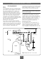
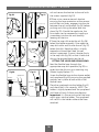
Fig.2 shows a recommended installation
where the hot water supply for the shower is
made via a tee connection on the underside
of the rising horizontal section of pipework
from the cylinder. Alternatively, the
For the operation of the shower only, it is
recommended that the cold water storage
cistern is capable of holding at least 114
litres (25 gallons). Where other hot and cold
Ring main
Mains supply
25mm min
Isolating
valve
Cold water cistern
Vent pipe
tee
Dedicated cold supply
Isolating spur
(3A fused)
outside bathroom
10m 75mm
max min
Isolating
valves
Isolating
valve
Hot supply
Hot water
cylinder
Alternative
connection
Shower
unit
Drain
valve
Fig.2 (Diagrammatic view – not to scale)
Other
hot water
draw-offs
4