1
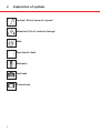
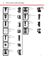
Installation and Operating Instructions
for Garage Sectional Door
GB
Last update: 08.2009
Einbau- und Bedienungsanleitung
für Garagen-Sectionaltor
GB
Stand: 01.2005
Einbau- und Bedienungsanleitung
für Garagen-Sectionaltor
F
Stand: 01.2005
Einbau- und Bedienungsanleitung
für Garagen-Sectionaltor
NL
Stand: 01.2005
Einbau- und Bedienungsanleitung
für Garagen-Sectionaltor
I
Stand: 01.2005
Einbau- und Bedienungsanleitung
für Garagen-Sectionaltor
E
Stand: 01.2005
Einbau- und Bedienungsanleitung
für Garagen-Sectionaltor
P
Stand: 01.2005
Einbau- und Bedienungsanleitung
für Garagen-Sectionaltor
S
Stand: 01.2005
Einbau- und Bedienungsanleitung
für Garagen-Sectionaltor
CZ
Stand: 01.2005
Einbau- und Bedienungsanleitung
für Garagen-Sectionaltor
H
Stand: 01.2005
Einbau- und Bedienungsanleitung
für Garagen-Sectionaltor
KR
Stand: 01.2005
Einbau- und Bedienungsanleitung
für Garagen-Sectionaltor
RUS
Stand: 01.2005
Note:
The instructions consist of two documents, one diagram and one text book.
2
1.
Table of Contents
1.
2.
3.
4.
5.
6.
7.
Table of Contents
Explanation of symbols
List of screws, bolts and plugs
Warranty
General safety information
Scope of delivery / Required tools
Installation of the sectional door
7.1
7.2
7.3
7.4
7.5
7.6
7.7
7.8
7.9
7.10
7.11
7.12
7.13
8.
Checking the dimensions
Mount the frames to the wall
Mounting the springs
Mounting the rails to the frame
Mounting the cables
Mounting the rails to the ceiling
Mounting the door sections
Mounting the cables to the door leaf
Setting the spring tension
Mounting the door link bracket
Mounting the pull cord
Re-mounting the cross strut (optional)
Testing the door travel
Maintenance instructions sectional door
3 GB
4
5
6
7
8
9
9
10
15
20
24
26
30
36
37
38
38
39
40
42
3
2.
Explanation of symbols
Caution! Risk of personal injuries!
Attention! Risk of material damage!
Note
Operational check
Reference
Text book
Picture book
4
List of screws, bolts and plugs
Type 8
Type 9:
6,5 mm x 25 mm
screw
13
Type 2:
4,2 mm x 13 mm
screw
M8
25
6,3
Type 1
GB
13
Type 8:
M8 x 13 mm
bolt
16
Type 1:
6,3 mm x 16 mm
screw
4,2
Type 9
10
Type 10:
M8 x 30 mm
bolt
50
Type 3:
Plug
6,5
30
Type 2
M8
Type 10
Type 4:
8 mm x 19 mm
washer
Type 11:
M6 x 16 mm
bolt
8
19
M6
Type 11
Type 5:
8 mm x 60 mm
screw
60
Type 4
16
Type 3
Type 5
Type 6:
6 mm x 10 mm
screw
10
8
Type 7:
M8 x 16 mm
bolt
16
3.
6
Type 6
M8
Type 7
5
4.
Warranty
Due to their frequent use wear parts have, a limited service life and are therefore
excluded from warranty!
The following are classed as wear parts:
• Springs
• Cables
• Rollers
• Seals
• Cable rollers
• Drive system
• Locks / Locking mechanism
• Bowden cables
• Hinges
Warranty with regard to functioning and safety can only be granted if:
• Installation is carried in compliance with these instructions
• Only original accessories are used
• No additional objects are fixed to the door
• Regular door maintenance is carried out
Warranty shall not apply if these installation and operating instructions are not
completely observed.
Subject to technical changes.
6
5.
General safety information
GB
Note:
Please keep these instructions for future reference!
Please read and always observe these instructions! They provide you with important
information regarding safe installation and operation of the sectional door. The instructions
also describe the correct care and maintenance of your door to ensure satisfaction with this
product for many years to come.
Caution:
• Installation should only be carried out by a person qualified for the task.
• For reasons of safety, only carry out the installation steps in the sequence
specified in these instructions.
• Only mount the door onto structurally sound and static surfaces which are
capable of supporting the door weight.
Intended use
• This garage door has been designed for private use only (approx. 1000 cycles / year).
• Continuous operation is strictly forbidden.
Site requirements for installation / operation:
At the construction site please ensure that:
• The floor is at its finished height
• The walls and ceiling have been plastered.
To eliminate the risk of corrosion:
• Provide sufficient drainage outside the garage in front of the floor seal and frame parts!
If necessary, plan a sloping run-off surface!
• Make sure that the building is dry and has sufficient ventilation!
• Protect the door against corrosive and caustic agents, e.g. saltpetre reactions from bricks
or mortar, acids, alkalis, road salt, corrosive paints or sealing compounds!
• Always cover the door before plastering or painting, since spots of mortar, cement,
plaster or paint can damage the surface.
7
6.
Scope of delivery / Required tools
Scope of delivery (fig. 6):
• Door leaf pack
• Frame pack
• Accessory pack
Required tools (not included):
• Two wooden trestles or other supporting equipment
• Electric drill
• Drills
• Torx T-20
• 4 mm Allen key
• 8 mm Allen key
• SW 13 socket spanner
• SW 10 socket spanner
• SW 13 socket spanner
• Suitable plugs for the special installation situation: Autoclaved aerated concrete
• Screwdriver
• Metal saw
• Pliers
• Protective glasses
• Screw clamps
• Ladder or scaffolding
• Spirit level
• Tube level for the metre level
• Tape measure
• Protective gloves
8
7.
Installation of the sectional door
7.1
Checking the dimensions
GB
Attention:
Prior to installation, please check whether the supplied door is suitable for the
proposed installation site.
Carry out the following measurements on the inside of the door opening (fig. 7.1):
A
Clearance width at the top and bottom of the door opening.
The supplied opening dimensions have to correspond to the door clearance width.
B
Clearance height on the right and left-hand side of the door opening.
The supplied opening dimensions have to correspond to the required door
clearance height.
C
Headroom on the right and on the left-hand side above the door opening.
– The headroom has to be at least 115 mm (for doors with electric drive).
– The headroom has to be at least 140 mm
(for very large doors with electric drive and 4x spring duct).
– The headroom has to be at least 240 mm
(for manually operated doors with exterior handle).
– The headroom has to be at least 265 mm
(for very large manually operated doors with exterior handle).
D
The sideroom on the right and left-hand side of the door opening has to be
at least 82.5 mm.
Operational check:
If all 4 requirements have been fulfilled, start installation.
Please see the order form for the opening dimensions.
9
7.
Installation of the sectional door
7.2
Mount the frames to the wall
Attention:
– It is important to install the lateral frames correctly to ensure that the door
completely covers the opening and is straight.
– The metre level is only valid for standard heights. For special heights
(shortened frame) the height level of the frame has to be transferred to the wall!
7.2 - a Determining the metre level
• Mark one of the opening sides:
One meter above the upper edge of the finished floor (OFF) (fig. 7.2 - 1).
• Transfer this measurement to the other opening side using the rear cross strut and a spirit
level (a tube level can also be used) (fig. 7.2 - 2).
• Now measure the transferred height. It has to be at least 1 m.
Note:
If the distance to the floor is less than 1 m on the other side, carry out the
measurement from this side!
7.2 - b Attaching the header frame
• Please remove the protective film from the header frame (fig. 7.2 - 3).
• Place the header seal on the header frame (Fig. 7.2 - 3).
• Place the spacer onto the gusset plate in the frame from below. (Fig. 7.2 - 4).
• Apply the silicone-free adhesive to the entire length of the covers.
Standard frame:
Fig. 7.2 - 5
Renovation frame:
Fig. 7.2 - 6
10
7.
Installation of the sectional door
GB
• Press the covers onto the frames.
Standard frame:
Fig. 7.2 - 7
Renovation frame:
Fig. 7.2 - 8
• Re-align the rubber seal of the frames by lifting the rubber seal along the entire length
with your thumbs or the heel of your hands (Fig. 7.2 - 9).
• Connect the vertical frames to the header frame (fig. 7.2 - 10).
Attention:
– Ensure that the elements are not damaged.
– Ensure that the surface of the frame is not scratched.
– Screw the elements together, making sure that the outer edges are flush.
• Use 2 sheet metal screws on each side to connect the elements:
Headroom version 115 mm:
fig. 7.2 - 11
Headroom version 240 mm:
fig. 7.2 - 12
• Fasten the screws.
7.2 - c Erecting the frame
Caution:
Two people are required to erect the frame.
Attention:
Ensure that the frame is neither twisted nor tilted during erection.
• Position the pre-assembled frame on the inside in front of the door opening (fig. 7.2 - 13).
11
7.
Installation of the sectional door
7.2 - d Aligning and attaching the frame
• Align the frame to the centre of the door opening (fig. 7.2 - 14).
• Align the embossed mark on the frame on both sides to the marks on the wall (fig. 7.2 - 15).
• Use screw clamps to fix this position (fig. 7.2 - 16).
• Measure the distance between the frames at the top and bottom
(fig. 7.2 - 14 and 7.2 - 17). Both distances have to be exactly the same.
• Clear frame dimensions = order dimensions width
• Check the diagonal dimensions (fig. 7.2 - 14)
• Check whether the frame is aligned horizontally in the door opening (fig. 7.2 - 18).
• Check whether the right and left-hand frame are aligned vertically in the door opening
(fig. 7.2 - 19).
• Check whether the right and left-hand frame are aligned vertically to the wall (fig. 7.2 - 20).
If the frame is not aligned correctly, use a shim at bottom.
Operational check:
All the aforesaid points have to be carried out to ensure perfect door travel.
12
7.
Installation of the sectional door
GB
7.2 - e Attaching the frame
Note:
There are two ways to attach the frame:
Mounting version 1 (inside mounting):
- If there is sufficient soffit behind the frame, screw the frame to the wall and floor
via the pre-cut holes (fig. 7.2 - 21 to 7.2 - 26).
Mounting version 2 (outside mounting):
- If there is not sufficient soffit behind the frame, screw on the frame,
use the installation brackets on the right and left-hand side of the frame to attach it
(fig. 7.2 - 27 to 7.2 - 31).
Mounting version 1 (inside mounting):
• Drill through the pre-cut holes in the frame (min. drilling depth 60 mm) – drill diameter
10 mm (fig. 7.2 - 22).
Attention:
The plug has to expand vertically!
• Insert the plug (fig. 7.2 - 23).
• Place the installation bracket into the frame and screw on the frame via the installation
bracket (fig. 7.2 - 23).
• Attach the installation bracket to the side of the frame using one bolt on each side
(fig. 7.2 - 24).
Screw frames with standard heights into the floor:
• Screw the frames to the floor (fig. 7.2 - 25).
Screw frames with special heights into the floor:
• Screw the frame to the floor (fig. 7.2 - 26).
13
7.
Installation of the sectional door
Mounting version 2 (outside mounting):
• Hold the installation bracket next to the frame at the height of the pre-cut holes.
Drill next to the frame (min. drilling depth 60 mm) through the installation bracket and
into the wall – drill diameter 10 mm (fig. 7.2 - 27).
Attention:
The plug has to expand vertically!
• Insert the plug (fig. 7.2 - 28).
• Place the installation angle onto the frame and screw the installation angle to the wall
(fig. 7.2 - 28).
• Attach the installation angle to the side of the frame using one bolt on each side
(fig. 7.2 - 29).
Screw frames with standard heights into the floor:
• Screw the frames to the floor (fig. 7.2 - 30).
Screw frames with special heights into the floor:
• Screw the frames to the floor (fig. 7.2 - 31).
Attention:
Fix the frame bracket to the wall twice (fig. 7.2 - 32)!
This is necessary regardless of whether the installation bracket has been installed
inside or next to the frame.
Note:
One screw fitting at the header frame is sufficient for door widths of up to 3 m.
Two screw fittings are necessary for door widths above 3 m.
The distance between these two screw fittings depends on the length of the header frame.
• Drill into the wall through the centre of the header frame (min. drilling depth 60 mm) –
drill diameter 10 mm (fig. 7.2 - 33).
• Screw the header frame to the wall (fig. 7.2 - 34).
14
7.
Installation of the sectional door
7.3
Mounting the springs
GB
7.3 - a Installation of the 2 and 3-spring assembly
Installing the springs
Attention:
Always keep spring components clean. Otherwise problems may arise during later
operation.
• Hook the springs into the "pulley block seat" (fig. 7.3 - 1).
• Use the two outer bore holes.
Attention:
If there is a third spring (depending on the door size), it should be hooked into
the centre bore hole.
• Attach one spring support from below to the springs (fig. 7.3 - 2).
Attention:
The spring support has to be attached as near to the end as possible (fig. 7.3 - 3).
• Attach a second spring support from below to the other end of the springs (fig. 7.3 - 4).
Attention:
The spring support has to be attached as near to the end as possible (fig. 7.3 - 5).
• Attach the other spring supports from below to the springs; ensure that they are equally
spaced (fig. 7.3 - 6).
• Insert bolt A into the bore hole of the angle plate.
• Fix the bolt with the respective nut B (fig. 7.3 - 7).
• Hook the angle plate onto the other end of the springs (fig. 7.3 - 8).
15
7.
Installation of the sectional door
• Use the two outer bore holes.
Attention:
If there is a third spring (depending on the door size), it should be hooked into
the centre bore hole.
Installation of the spring assembly into the rail
Note:
The figure shows installation on the right-hand side. Installation on the
left-hand side has to be carried out laterally reversed.
• Slide the pre-assembled spring assembly into the rail until only the pulley block protrudes
from the rail (fig. 7.3 - 9).
Attention:
– Lay the cables straight and ensure that they are not twisted.
– Pull the cable through the pulley block in a way that the squeezed cable
ends C face the outside of the frame A and the plastic loop D faces the
inside of the frame B.
• Pull the squeezed cable ends C through the pulley block (fig. 7.3 - 10).
• Make sure the cable has been laid correctly.
• Pull the cable through the pulley block until the two ends are of equal length
(fig. 7.3 - 11).
• Insert the cable locks into both sides of the pulley block seat (fig. 7.3 - 12).
Attention:
Fully insert the cable locks up to the limit stop in the pulley block seat
(fig. 7.3 - 13).
• Pull the spring assembly until approximately 10 mm of bolt A protrudes from the bore
hole at the end of the rail (fig. 7.3 - 14).
16
7.
Installation of the sectional door
GB
• Screw the nut onto the bolt protruding from the rail (fig. 7.3 - 15).
• Screw the nut as far as necessary until all the threads engage.
Note:
This nut is later used to set the spring tension at the door.
7.3 - b Installation of the 4-spring assembly
Assembling the spring assembly
Attention:
Always keep spring components clean.
Otherwise problems may arise during later operation.
• Hook the springs into the "pulley block seat" (fig. 7.3 - 16).
• Use the two lower bore holes.
• Attach one spring support to the springs from below (fig. 7.3 - 17).
Attention:
The spring support has to be mounted as near to the end as possible
(fig. 7.3 - 18).
• Attach a second spring support to the other end of the springs from below (fig. 7.3 - 19).
Attention:
The spring support has to be mounted as near to the end as possible
(fig. 7.3 - 20).
• Attach the remaining spring supports from below to the springs; ensure that they are
equally spaced (fig. 7.3 - 21).
• Fix bolt A in the angle plate using the respective nut B (fig. 7.3 - 22).
17
7.
Installation of the sectional door
• Hook the angle plate onto the other end of the springs (fig. 7.3 - 23).
Use the two lower bore holes.
• Insert the third and fourth springs into the "pulley block seat" (fig. 7.3 - 24).
Use the two upper bore holes.
• Insert the third and fourth springs into the angle plate at the other end (fig. 7.3 - 25).
Use the two upper bore holes.
Installation of the spring assembly into the rail
Note:
The figure shows installation on the right-hand side.
Assembly on the left-hand side is carried out laterally reversed.
• Slide the pre-assembled spring assembly into the rail until only the pulley block protrudes
from the rail (fig. 7.3 - 26).
Attention:
– Lay the cables straight and ensure that they are not twisted.
– Pull the cable through the pulley block in a way that the squeezed cable
ends C face the outside of the frame A and the plastic loop D faces the
inside of the frame B.
• Pull the squeezed cable ends C through the pulley block (fig. 7.3 - 27).
• Make sure the cable has been laid correctly.
• Pull the cable through the pulley block until the two ends are of equal length
(fig. 7.3 - 28).
• Insert the cable locks into both sides of the pulley block seat (fig. 7.3 - 29).
18
7.
Installation of the sectional door
GB
Attention:
Fully insert the cable locks up to the limit stop in the pulley block seat
(fig. 7.3 - 30).
• Pull the spring assembly until approximately 10 mm of bolt A protrudes from the bore
hole at the end of the rail (fig. 7.3 - 31).
• Screw the nut onto the bolt protruding from the rail (fig. 7.3 - 32).
• Screw the nut as far as necessary until all the threads engage.
Note:
This nut is later used to set the spring tension at the door.
19
7.
Installation of the sectional door
7.4
Mounting the rails to the frame
7.4 - a Preparing the upper rails
Note:
The following figure shows installation on the inside on the right. Installation on
the inside on the left has to be carried out laterally reversed.
• Insert the rollers and the spacers into the frame brackets on the right and left-hand side
(fig. 7.4 - 1).
• Secure the bolt with spring pin A.
• Place a black plastic curved rail on the right and left-hand rail (fig. 7.4 - 2).
Attention:
When fixing, the bolt has to be inserted from the inside into the curved rail.
The respective nut is screwed on from the outside of the curved rail.
Otherwise the screw fitting could block door travel later on.
• Tighten the nuts and bolts of the curved rail (fig. 7.4 - 3).
7.4 - b Attaching the upper rail
Attention:
When fixing, the bolt has to be inserted from the inside into the curved rail.
The respective nut is screwed on from the outside of the curved rail.
Otherwise the screw fitting could block door travel later on.
• Fix the pre-assembled curves with just one bolt to the side of the frame brackets
(fig. 7.4 - 5).
Attention:
Only tighten the bolts slightly at first!
20
7.
Installation of the sectional door
GB
7.4 - c Attaching the upper cross strut
• Screw the cross strut connectors to the ends of the strut on both sides.
For this, insert the pin of the connector into the small bore hole in the strut
(fig. 7.4 - 6).
• Screw the cross strut to the end of the hanging rails (fig. 7.4 - 7).
Note:
The cross strut may have to be remounted if an electric drive is retrofitted.
See point 7.12 for the required remounting steps.
21
7.
Installation of the sectional door
Cable sleeves to be used for 115 mm headroom version
Cable sleeve to be used for 40 mm panel thickness (fig. 7.5 - 1)
H/B 2000 2250 2375 2500 2625 2750 3000 3250 3500 3750 4000 4250 4500 4750 5000 5250 5500
1875 1
1
2
2
2
1
1
3
3
3
3
1
1
1
3
3
3
2000 1
1
2
2
2
1
1
3
3
3
3
1
1
1
3
3
3
2125 1
1
2
2
2
1
1
2
2
2
2
1
1
1
3
3
2
2250 1
1
2
2
2
1
1
2
2
2
2
1
1
1
3
2
2
2375 4
4
1
1
1
1
1
1
4
4
1
1
1
1
4
4
4
2500 4
1
1
1
1
1
1
1
4
4
1
1
1
1
4
4
4
2625 3
3
3
3
3
3
3
3
3
3
1
3
3
3
3
2750 3
3
3
3
3
3
3
3
3
3
1
3
3
3
3
2875 1
1
1
1
1
1
1
1
2
1
2
1
1
3000 1
1
1
1
1
1
1
1
2
1
2
1
1
Cable sleeve to be used for 20 mm panel thickness (fig. 7.5 - 1)
H/B 2000 2250 2375 2500 2625 2750 3000 3250 3500 3750 4000 4250 4500 4750 5000 5250 5500
1875 1
1
1
2
2
3
1
1
3
3
3
3
3
1
1
2000 1
1
1
2
2
3
1
1
3
3
3
3
3
1
1
2125 1
1
1
2
2
2
1
1
4
2
2
2
2
2
1
2250 1
1
1
2
2
2
1
1
4
2
2
2
2
2
1
2375 4
4
4
1
1
1
1
1
1
4
1
1
2500 4
4
4
1
1
1
1
1
1
4
1
2625 3
3
3
3
3
3
3
3
3
3
2750 3
3
3
3
3
3
3
3
3
3
2875 2
1
1
1
1
1
1
1
1
3000 2
1
1
1
1
1
1
1
Cable sleeves to be used for aluminium profiles (fig. 7.5 - 1)
H/B 2000 2250 2375 2500 2625 2750 3000 3250 3500 3750 4000 4250 4500 4750 5000 5250 5500
1875 1
1
1
1
2
3
1
1
3
3
3
3
3
1
3
2000 1
1
1
1
2
3
1
1
3
3
3
3
3
1
3
2125 1
1
1
1
2
2
1
1
3
2
2
2
2
1
3
2250 1
1
1
1
2
2
1
1
3
2
2
2
2
1
3
2375 4
4
4
1
1
1
1
1
1
4
1
1
2500 4
4
4
1
1
1
1
1
1
4
1
2625 3
3
3
3
3
3
3
3
3
3
2750 3
3
3
3
3
3
3
3
3
3
2875 2
1
1
1
1
1
1
1
1
3000 2
1
1
1
1
1
1
1
H = Height / B = Width
22
7.
Installation of the sectional door
GB
Cable sleeves to be used for 240 mm headroom version
Cable sleeve to be used for 40 mm panel thickness (fig. 7.5 - 1)
H/B 2000 2250 2375 2500 2625 2750 3000 3250 3500 3750 4000 4250 4500 4750 5000 5250 5500
1875 1
1
2
2
2
1
1
3
3
3
3
1
1
1
3
3
3
2000 1
1
2
2
2
1
1
2
2
2
2
1
1
1
3
3
2
2125 1
1
2
2
2
1
1
2
2
2
2
1
1
1
3
2
2
2250 4
4
1
1
2
1
1
1
4
1
1
1
1
1
4
4
4
2375 4
1
1
1
1
1
1
1
4
1
1
1
1
1
4
4
4
2500 3
3
3
3
1
3
3
3
3
3
3
3
3
3
3
4
4
2625 3
3
3
3
3
3
3
3
3
3
1
3
3
3
3
2750 1
1
1
1
3
1
1
1
2
2
2
1
1
3
3
2875 1
1
1
1
1
1
1
1
2
1
2
1
1
3000 1
1
1
1
1
1
1
1
2
1
2
1
1
Cable sleeve to be used for 20 mm panel thickness (fig. 7.5 - 1)
H/B 2000 2250 2375 2500 2625 2750 3000 3250 3500 3750 4000 4250 4500 4750 5000 5250 5500
1875 1
1
1
2
2
3
1
1
3
3
3
3
3
1
1
2000 1
1
1
2
2
2
1
1
4
2
2
2
2
1
1
2125 1
1
1
2
2
2
1
1
4
2
2
2
2
1
1
2250 4
4
4
1
1
1
1
1
1
4
1
1
1
1
2
2375 4
4
4
1
1
1
1
1
1
4
1
1
2500 3
3
3
3
3
3
3
3
3
3
3
2625 3
3
3
3
3
3
3
3
3
3
2750 2
1
1
1
1
1
1
1
1
1
2875 2
1
1
1
1
1
1
1
1
3000 2
1
1
1
1
1
1
1
Cable sleeves to be used for aluminium profiles (fig. 7.5 - 1)
H/B 2000 2250 2375 2500 2625 2750 3000 3250 3500 3750 4000 4250 4500 4750 5000 5250 5500
1875 1
1
1
1
2
1
1
1
3
3
3
3
3
1
3
2000 1
1
1
1
2
2
1
1
3
2
2
2
2
1
3
2125 1
1
1
1
2
2
1
1
3
2
2
2
2
1
3
2250 4
4
4
1
1
1
1
1
1
4
1
1
1
1
2
2375 4
4
4
1
1
1
1
1
1
4
1
1
2500 3
3
3
3
3
3
3
3
3
3
3
2625 3
3
3
3
3
3
3
3
3
3
2750 2
1
1
1
1
1
1
1
1
1
2875 2
1
1
1
1
1
1
1
1
3000 2
1
1
1
1
1
1
1
23
7.
Installation of the sectional door
7.5
Mounting the cables
7.5 - a Laying the cables
Attention:
Lay the cables straight and ensure that they are not twisted.
The door will not open and close correctly if it has been installed incorrectly.
The cable may break.
• Make sure the cables have been laid correctly.
Note:
The cables used can have up to 4 cable sleeve pairs.
The example displays the situation when cable sleeve 1 has to be used
(fig. 7.5 - 1).
• See the tables above to discover which sleeves should be used.
• Insert the determined sleeves into the cable support at the frame (fig. 7.5 - 2).
• Use the black plastic stop to secure the cables in the frame (fig. 7.5 - 3).
Caution:
When the cable is pulled over the pulley block a counterforce is created due to
the spring tension. The cable has to be secured.
• Feed the other end of the cable over the pulley block (fig. 7.5 - 4).
• Pull the cable to the first installation bracket.
• Insert the bolt through the loop and the bore hole in the installation bracket / frame
(fig. 7.5 - 5).
• Fix the bolt with the nut (fig. 7.5 - 5).
• Install the opposite side as described above (fig. 7.5 - 1 to 7.5 - 5).
24
7.
Installation of the sectional door
GB
7.5 - b Mounting the spring duct cover (2 and 3-spring assembly)
Attention:
Before covering the spring duct please ensure that
- the cables are not twisted
- the cables run smoothly
- the cable ends are fixed
- the spring duct is free from dust and dirt.
• Place the cover onto the spring duct starting from the side of the cross strut connection,
so that the entire length of the spring duct is covered (fig. 7.5 - 6 and 7.5 - 7).
• Push the cover onto the spring duct until it engages.
The profile of the cover has to fit into the profile of the spring duct (fig. 7.5 - 8).
7.5 - c Mounting the spring duct cover (4-spring assembly)
Attention:
Before covering the spring duct please ensure that
- the cables are not twisted
- the cables run smoothly
- the cable ends are fixed
- the spring duct is free from dust and dirt.
• Screw the cover onto the spring duct using the holes provided (fig. 7.5 - 9).
25
7.
Installation of the sectional door
7.6
Mounting the rails to the ceiling
7.6 - a Attaching and aligning the upper rails
Attention:
– Make sure that the frame assemblies are not tilted while being raised.
– The lateral rails and the cross strut have to be aligned exactly horizontally.
• Raise the screwed frame assemblies at the same time and support them (fig. 7.6 - 1).
• Align the cross strut horizontally (fig. 7.6 - 2).
• Align the runner rails horizontally (fig. 7.6 - 3).
• Tighten the pre-assembled bolt between the frame and rail (fig. 7.6 - 4).
• Screw the left and right-hand plastic curved rail (torx T20) to the frame using two screws
for each rail (fig. 7.6 - 5).
7.6 - b Mounting the lower curved rail
• Insert the curved rail on right and left-hand side between the vertical and horizontal rails
(fig. 7.6 - 6).
Attention:
When fixing, the bolt has to be inserted from the inside into the curved rail.
The respective nut is screwed on from the outside of the curved rail.
Otherwise the screw fitting could block door travel later on
• Tighten the nuts and bolts of the curved rail (fig. 7.6 - 7 and 7.6 - 8).
• Align the runner rail joint until it is flush (fig. 7.6 - 7 and 7.6 - 8).
Note:
Use pliers to smooth out any joints which might obstruct door travel.
26
7.
Installation of the sectional door
GB
Attention:
The runner rails have to be aligned in parallel with each other to guarantee
correct door travel.
Note:
The runner rails are aligned correctly if both diagonal measurements have the
same length. To achieve an exact measurement, use the same measuring points
for each diagonal measurement.
• Measure the diagonal lengths and align the runner rails parallel with each other
(fig. 7.6 - 9).
7.6 - c Mounting the suspensions to the runner rails
Attention:
Prior to mounting the suspension, the door has to be aligned as described above
(see fig. 7.6 - 9).
Legend (fig. 7.6 - 10):
A
Suspension
B
Suspension for mounting version 1
C
Suspension for mounting version 2
Attention:
– It is absolutely essential that the suspensions A are mounted.
– Three suspensions have to be attached to each side.
Note:
Normally suspension A has to be used. This suspension is described below.
Suspension D is used for the special case of "insufficient sideroom"
(fig. 7.6 - 11).
• Make sure which suspension suits your requirements.
• Hold the suspension together with the installation bracket to determine the required
length. Mark any extra length of the suspension projecting from the frame (fig. 7.6 - 12).
27
7.
Installation of the sectional door
Note:
To ensure maximum runner rail stability, the suspension should project slightly,
or be at least flush with the lower edge of the horizontal frame.
• Saw off any projecting length at the marked position (fig. 7.6 - 13).
Caution:
To avoid injuries, screw the installation bracket to the sawn off end of the
suspension.
• Screw the installation bracket to the suspension (fig. 7.6 - 14).
Attention:
Please ensure that the spring duct is covered prior to drilling.
• Hold the pre-assembled suspension to the runner rail and mark the drilling spot.
Drill at least 60 mm into the ceiling – drill diameter 10 mm (fig. 7.6 - 15).
Attention:
When fixing, the bolt has to be inserted from the inside into the curved rail.
The respective nut is screwed on from the outside of the curved rail.
Otherwise the screw fitting could block door travel later on.
• Laterally screw the suspension to the runner rails (fig. 7.6 - 16).
• Insert the plug into the drilled hole and screw the suspension to the ceiling (fig. 7.6 - 17)
• Mount all further suspensions as described above (fig. 7.6 - 12 - 7.6 - 17).
28
7.
Installation of the sectional door
GB
Mounting for the special case of "insufficient sideroom"
• Screw the runner rails to the suspensions D (fig. 7.6 - 18).
Note:
In order to laterally stabilise the door it is necessary to mount a wall strut or a
lateral ceiling strut.
Mounting version 1 (fig. 7.6 - 10)
• If the length of the suspension allows a wall strut on the right or left-hand side of the
wall, mount suspension B (fig. 7.6 - 10 and 7.6 - 19).
• Adjust the clearance from the wall using the telescopic function (Fig. 7.6 - 19).
Mounting version 2 (fig. 7.6 - 10)
• If the length of the suspension does not allow a wall strut on the right or left-hand side
of the wall, mount suspension C (fig. 7.6 - 10 and 7.6 - 20).
29
7.
Installation of the sectional door
7.7
Mounting the door sections
7.7 - a Preparing the bottom door section
All the sectional door panels are covered with a protective film. Depending on the height of
the panel, this film may also be in the area around the rounded edge A.
• Remove the protective film from around the rounded edge prior to assembling the panels
(fig. 7.7 - 2).
Note:
Please leave the protective film on the outside surface of the panel until the door
is fully mounted.
Note:
The side sticker "Bodensection" (bottom section) and the shortened end caps
help you to recognise the bottom door section (fig. 7.7 - 3 and 7.7 - 4).
• Place the bottom door section ready for installation, if possible, on the trestles
(fig. 7.7 - 1).
• Insert the bottom door section profile onto the bottom door section (fig. 7.7 - 4).
4 versions of the bottom door section profile are available:
0 mm, 9 mm, 17 mm, 32 mm (fig. 7.7 - 5)
• Screw the bottom door section profile in the middle to the bottom door section.
• In case of manually operated doors, please attach the optional handle (fig. 7.7 - 6).
• Place the bottom section in the centre of the door opening.
• Insert the roller into the bottom bracket (only 2 and 3 spring system).
• Slide the roller together with the bottom bracket into the runner rail.
(only 2 and 3 spring system).
Attention:
Do not drill through the door leaf (max. depth 25 mm)!
30
7.
Installation of the sectional door
GB
• Hold the bottom bracket to the inside of the door leaf in a way that the bore holes in
door leaf match the four lower bore holes in the bottom bracket.
• Mark the drilling spots for the upper screwing fittings.
Information for SKG / WK2 (wind resistance class 2) door types:
When using break-in protection, the cover plate has to be screwed into the frame
before installing the bottom section.
• Hold the bottom bracket in place at the installation position.
• Screw the cover plate of the break-in protection to the bottom section on both sides
(Fig. 7.7 – 7).
• Drill the holes. Drill diameter 4.5 mm:
2 and 3 spring system (fig. 7.7 – 8)
4 spring system (fig. 7.7 – 9)
• Screw the bottom bracket to the bottom door section:
2 and 3 spring system (fig. 7.7 – 10)
4 spring system (fig. 7.7 – 11)
Note for 4 spring duct:
When using the 4 spring duct, the door has to be aligned in the middle between
the runner rails with spacer rings (max 8 rings – fig. 7.7 - 12).
• Insert the roller into the roller holder (only 4 spring system, fig. 7.7 - 12).
• Insert the roller into the runner rail and screw the roller holder onto the bottom bracket
(only 4 spring system, fig. 7.7 - 13).
• Follow these steps to mount the bottom bracket to the bottom section on both sides.
31
7.
Installation of the sectional door
Attention:
To lighten the bottom door profile, use shims to support the bottom section.
• Place blocks of wood underneath both sides of the bottom bracket:
2 and 3 spring system (fig. 7.7 – 14)
4 spring system (fig. 7.7 – 15)
– The blocks of wood should be high enough to ensure that the bottom door profile
is not crushed.
– After shimming, the door leaf has to be horizontally level and level with the upper edge
of the finished floor OFF.
7.7 - b Mounting further door sections
Caution:
The sections could fall down as long as they are not attached to the previous
section and the roller holders have not been mounted.
• Secure every new section placed into the opening.
• Place the section with the type plate onto the bottom section (fig. 7.7 - 16).
•Insert the spacers between the sections (Fig. 7.7 - 16).
Note:
The spacers must be removed after screwing the sections together. The spacers
must be re-inserted between the sections before unscrewing the sections.
• Insert the rollers into the roller holders:
2 and 3 spring system (fig. 7.7 – 17)
4 spring system (fig. 7.7 – 18)
Note for headroom version 240 mm only:
Now mount the handle.
The installation instructions are in the handle pack.
32
7.
Installation of the sectional door
GB
Attention:
Do not drill through the door leaf (max. depth 25 mm)!
• Insert the roller with the roller holder into the runner rail
(only 2 and 3 spring system).
• Screw the roller holders to the door leaf via the pre-drilled holes
(only 2 and 3 spring system, fig.7.7 – 19).
• Drill the hole for the bottom screw fitting
(drill diameter 4.5 mm, only 2 and 3 spring system, fig.7.7 – 19).
• Screw the roller holder to the bottom screw fittings
(only 2 and 3-spring system, fig.7.7 – 19).
• Screw the lateral hinges to the door leaf at the pre-drilled bore holes
(only 4-spring system, fig. 7.7 – 20)
• Insert the roller into the runner rail and screw the roller holder to the lateral hinge
(only 4-spring system – fig. 7.7 - 21).
• Screw the sections in the centre of the door leaves (fig. 7.7 - 22).
• Check whether the door is aligned horizontally (fig. 7.7 - 23).
Note:
To align the door horizontally, you can adjust the height of the wooden blocks
(see fig. 7.7 - 14 and 7.7 - 15).
• Mount all further sections, except the top section (with sticker top section),
as described above (fig. 7.7 - 16 to 7.7 - 23).
Note:
Mounting of the top section is described on the following pages.
33
7.
Installation of the sectional door
7.7 - c Mounting the upper door section (top section)
• Place the emergency release housing A from the outside through the provided opening
in the top section (fig. 7.7 - 24).
• Screw the housing A to the counter plate B (fig. 7.7 - 24).
• Mount the cover plate C on top of the emergency release housing (fig. 7.7 - 25).
Note:
The top section of special door sizes is rounded off with an aluminium profile D
(fig. 7.7 - 26).
• Place the top section onto the previous section and attach it as described above
(see fig. 7.7 - 16 to 7.7 - 23).
Attention:
The roller support plate which is to be screwed on has to be flush with the
outside of the upper door section.
• Release bolts A (fig. 7.7 - 28).
• Insert the roller of the upper roller holder into the black plastic curved rail.
• Screw the roller holding plates onto the right and left-hand side of the upper door leaf
(fig. 7.7 - 28).
Note only for headroom version 240 mm:
For the special case of headroom version 240 mm, the lower drilling template has
to be used to mount the roller holding plate (fig. 7.7 - 29).
• Align the roller in the upper curved rail as follows (fig. 7.7 - 30):
Position 1:
For doors with an electric drive =
Roller is on TOP in the curved rail.
Position 2:
For doors without an electric drive (manual operation) =
Roller engages just behind the vertical curved rail section.
34
7.
Installation of the sectional door
GB
Attention:
If you wish to retrofit an electric drive, you have to change the position of the
roller to position 1.
• Ensure that the space between the roller and the roller holder is 1 – 2 mm along the
entire length of the door (fig. 7.7 - 31).
• As soon as you have adjusted your door to the correct position, tighten the bolts A
(fig. 7.7 - 32).
Attention:
– Alignment of the roller holders should only be carried out when the door
is closed.
– The locking screws should not be tightened too tightly.
• Align all the roller holders in a way that the rollers are placed in the radius of the runner
rails.
2 and 3-spring system
• Release the locking screw of "roller bracket" – 4 mm Allen key (fig. 7.7 - 33).
• Move the roller until it is in the correct position – bracket in the middle, 8 mm Allen key
(fig. 7.7 - 33).
• Retighten the locking screw (fig. 7.7 - 33).
4-spring system
• Loosen the M6 nuts (fig. 7.7 – 34).
• Adjust the plastic roller holder until the roller is set correctly (fig. 7.7 – 34).
• Retighten the M6 nuts (fig. 7.7 – 34).
35
7.
Installation of the sectional door
7.8
Mounting the cables to the door leaf
Attention:
The door is not yet under spring tension.
The force required to open the door is not supported by spring tension.
• Open the door carefully up to end position (fig. 7.8 - 1).
Note:
The following diagrams always display the right-hand inside of the door.
• Secure the open door on right and left-hand side to the runner rail using screw clamps
(fig. 7.8 - 2).
Attention:
You must have free access to the bolt at bottom bracket (fig. 7.8 - 3).
Caution:
The cable is under tension due to the spring.
• Hold the cable firmly.
• Do not release the cable until it has been secured.
• Remove the screw on installation bracket / frame (fig. 7.8 - 4).
• Place the cable loop onto the lateral receiver at the bottom bracket.
• Secure the cable loop with an SL securing device (fig. 7.8 - 5).
Note:
The steps have to be carried out laterally reversed on the other side of the door
side (see fig. 7.8 - 2 to 7.8 - 5).
36
7.
Installation of the sectional door
GB
Caution:
Make sure that the cable loop is secured before removing the screw clamps.
• Now remove the screw clamps (see fig. 7.8 - 2).
• Remove the blocks of wood (see fig. 7.7 - 14 and 7.7 - 15).
7.9
Setting the spring tension
• Close the door and test the spring tension (fig. 7.9 - 1).
Attention:
– Spring tension should only be changed when the door is open.
– Both sides should always have the same tension.
– When reducing the spring tension, the threaded rod should never be unscrewed
from the nut.
– The tension has to be set in away which enables simple up or down travel.
– The cable has to have sufficient initial tension in every door position.
– The cable should always be under tension!
• To increase tension, turn the M8 nut clockwise (fig. 7.9 - 2).
37
7.
Installation of the sectional door
7.10 Mounting the door link bracket
• Mount the door link bracket in the centre of the top door section (fig. 7.10 - 1).
Note:
The door link bracket should be screwed on, even if an electric drive has not yet
been fitted. The door link bracket is specially designed for this sectional door and
should be used if an electric drive is retrofitted.
7.11 Mounting the pull cord
Caution:
To avoid injuries, never use the cable in connection with an electric drive!
Always remove an existing cable if an electric drive is retrofitted to the door!
For door heights from 2250 mm and higher:
• Insert the pull cord from below through the flap of the bottom bracket and knot the end
of the cord (fig. 7.11 - 1).
• Insert the pull cord from the front through the hole in the horizontal frame
(fig. 7.11 - 2).
• Pull the cord to the required length and knot the end.
38
7.
Installation of the sectional door
GB
7.12 Re-mounting the cross strut (optional)
Note:
If the rear cross strut does not allow the installation of an electric drive,
it can be re-mounted.
Attention:
– The door should only be moved after the rear cross strut has been mounted!
– Only dismount the cross strut when the door is closed!
• Dismount the back cross strut (fig. 7.12 - 1).
• Remove the connectors A on both sides of the cross strut (fig. 7.12 - 1).
• Mount the connecting angles to both sides of the cross strut (fig. 7.12 - 2).
• Fix the cross strut to the very last connection in the lower runner rail (fig. 7.12 - 3).
Attention:
Do not mount the cross strut further towards the front, since it would block the
travel of the door.
39
7.
Installation of the sectional door
7.13 Testing the door travel
Caution:
To avoid injuries, check whether the door is secure:
- Have all installation steps been carried out?
- Have the lateral rails been sufficiently fixed?
- Are the springs on both sides under sufficient tension as described?
- Have the door sections been attached at all the specified positions
and has the space of 2 mm between the sections been adhered to?
• Open and close the door manually (fig. 7.13).
Successful testing of the door should fulfil the following requirements:
1. The door travels easily.
• If the door does not travel easily, please check:
– Have all the lateral frames been aligned correctly (see point 7.2 -e)?
– Have the cables been twisted (see point 7.5)?
– Have the lateral runner rails been aligned horizontally (see point 7.6 - a)?
– Has the door leaf been aligned in the centre of the door opening (see point 7.7 - b)?
– Is the door leaf, when closed, in a horizontal position (see point 7.7 - b)?
2. The door travels to the end positions "Door OPEN" and "Door CLOSED".
• If the door cannot travel to the end position "Door OPEN", please check:
- Is an object obstructing door travel? Especially check the runner rails.
- Does the cable run correctly over the pulley blocks on both sides (see point 7.5)?
- Is the tension of the spring correct (see point 7.9)? The spring tension is possibly too
low or too high.
3. The door should stop immediately between the end positions after being released.
• If the door does not stop immediately, please check:
- If the door carries on opening, reduce the spring tension (see point 7.9).
- If the door carries on closing, increase the spring tension (see point 7.9).
40
7.
Installation of the sectional door
GB
Attention:
The protective film on the outside of the sections has to be removed;
otherwise strong sunlight will cause it to stick to the sections!
• Remove the protective film from the outside of the sections.
41
8.
Maintenance instructions sectional door
Necessary maintenance from points 1 and 3 should only be carried out by people qualified
for these tasks.
Maintenance should be carried at least every 12 months.
Maintenance points:
1.
2.
3.
4.
5.
6.
7.
8.
42
Check the steel cables for fractures.
Check the rollers.
Lubricate the hinges and the rollers.
If necessary, re-tension the springs.
Check the springs.
Check the roller settings.
Check the condition and fixing of all screws and nuts and bolts.
Carry out a visible inspection of all the components for fractures and damages
GB
43
08/09 (GB) 119.311
D
GB
F
NL
I
E
P
S
N
DK
CZ
PL
H
HR
GR
SLO
RUS
08.2009
6
6
2
7.1
D
7.1
C
C
A
B
B
A
D
D
3
7.2
OFF
7.2 - 2
7.2 - 3
4
1m
7.2 - 1
7.2
D
7.2 - 4
7.2 - 5
7.2 - 6
7.2 - 7
7.2 - 8
5
7.2
7.2 - 9
7.2 - 10
7.2 - 11
Typ 2
6
7.2 - 12
Typ 2
7.2
D
7.2 - 13
7.2 - 14
7
7.2
7.2 - 15
7.2 - 16
7.2 - 17
7.2 - 18
7.2 - 19
7.2 - 20
8
7.2
D
7.2 - 21
9
7.2
7.2 - 22
7.2 - 23
ø 10
Typ 3 / 4 / 5
7.2 - 24
7.2 - 25
Typ 8
Typ 3 / 4 / 5
7.2 - 26
Typ 3 / 4 / 5
10
7.2
7.2 - 27
7.2 - 28
ø 10
Typ 3 / 4 / 5
7.2 - 29
7.2 - 30
Typ 8
Typ 3 / 4 / 5
D
7.2 - 31
Typ 3 / 4 / 5
11
7.2
7.2 - 32
7.2 - 33
ø 10
7.2 - 34
Typ 3 / 4 / 5
12
7.3
7.3 - 1
7.3 - 2
7.3 - 3
7.3 - 4
D
7.3 - 5
13
7.3
7.3 - 6
7.3 - 7
A
B
14
7.3 - 8
7.3
D
7.3 - 9
7.3 - 10
C
B
D
A
7.3 - 11
15
7.3
7.3 - 12
7.3 - 14
A
7.3 - 15
16
7.3 - 13
7.3
7.3 - 16
7.3 - 17
7.3 - 18
7.3 - 19
D
7.3 - 20
17
7.3
7.3 - 21
7.3 - 22
7.3 - 23
A
B
7.3 - 24
18
7.3 - 25
7.3
D
7.3 - 26
7.3 - 27
C
B
D
A
7.3 - 28
19
7.3
7.3 - 29
7.3 - 31
A
7.3 - 32
20
7.3 - 30
7.4
D
7.4 - 1
A
7.4 - 2
7.4 - 3
Typ 8
21
7.4
7.4 - 4
7.4 - 5
Typ 7
22
7.4
7.4 - 6
Typ 8
D
7.4 - 7
Typ 8
23
7.5
7.5 - 1
7.5 - 2
4
7.5 - 3
7.5 - 5
Typ 10
24
3
2
1
7.5 - 4
7.5
D
7.5 - 6
7.5 - 7
7.5 - 8
25
7.5
7.5 - 9
26
7.6
D
7.6 - 1
7.6 - 2
7.6 - 3
27
7.6
7.6 - 4
7.6 - 5
Typ 6
28
7.6
D
7.6 - 6
7.6 - 7
Typ 8
7.6 - 8
Typ 8
7.6 - 9
29
7.6
7.6 - 10
A
A
C
A
A
B
7.6 - 11
D
7.6 - 13
7.6 - 12
A
7.6 - 14
Typ 8
30
7.6
7.6 - 15
D
7.6 - 16
Typ 8
7.6 - 17
Typ 3 / 4 / 5
7.6 - 19
Typ 3 / 4 / 5
7.6 - 18
Typ 8
7.6 - 20
Typ 8
31
7.7
7.7 - 1
7.7 - 2
7.7 - 3
A
32
7.7
D
7.7 - 4
32 mm
17 mm
7.7 - 6
9 mm
0 mm
7.7 - 5
Typ 1
7.7 - 7
4,8x13
33
7.7
7.7 - 8
7.7 - 9
7.7 - 10
7.7 - 11
Typ 11
Typ 1
34
Typ 1
7.7
7.7 - 12
7.7 - 13
7.7 - 14
7.7 - 15
D
35
7.7
7.7 - 16
Hersteller-Nr. 63* Guetegemeinschaft ttz
D-58095 Hagen
EN 13241-1
Jahr:
Artikel:
Handbetaetigtes Tor
Wasserdichtheit
Windlast
Waermewiderstand
Luftdurchlaessigkeit
=
0 mm
=
0 mm
89/106/EWG
7.7 - 17
36
7.7 - 18
7.7
7.7 - 19
D
7.7 - 20
Typ 11
Typ 1
Typ 1
7.7 - 21
7.7 - 22
Typ 1
7.7 - 23
37
7.7
7.7 - 24
A
B
7.7 - 26
D
7.7 - 27
38
7.7 - 25
C
7.7
7.7 - 28
D
7.7 - 29
A
Typ 1
7.7 - 30
1
7.7 - 31
2
7.7 - 32
A
39
7.7
7.7 - 33
40
7.7 - 34
7.8
D
7.8 - 1
7.8 - 2
7.8 - 3
7.8 - 4
7.8 - 5
41
7.9
7.9 - 1
7.9 - 2
42
7.10
D
7.10
7.11
7.11 - 1
7.11 - 2
43
7.12
7.12 - 1
7.12 - 2
A
7.12 - 3
44
7.13
D
7.13
45
46
D
47
08/09 (D, GB, F, NL, I, E, P, S, N, DK, CZ, PL, H, HR, GR, SLO, RUS) 123.165