1
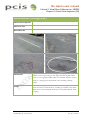
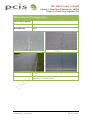
the ukpms user manual
Volume 2
Visual Data Collection for
UKPMS
Chapter 7: Coarse Visual
Inspection (CVI)
the ukpms user manual
Volume 2: Visual Data Collection for UKPMS
Chapter 7: Coarse Visual Inspection (CVI)
Document Information
Title (Sub Title)
The UKPMS User Manual
Volume 2: Visual Data Collection for UKPMS
Chapter 7: CVI
UKPMS Manual July 2009
James Wallis
This chapter describes the UKPMS Coarse Visual Inspection
(CVI).
Product Number
Author
Description
Document History
Version
No
Status
Author
Date
01
02
Draft
Released
JW
JW
01/02/05
06/05/05
03
04
05
Revised
Final
Update
JW
JW
JW
30/06/06
July 2005
Feb 2007
06
07
08
08a
Revised
Review
Revised
amendment
July 2009
Sept 2009
Oct 2009
24 Oct 09
09
09a
Final
ammendment
JW
JW
KAG
KAG/A
P
ME
ME
30 Oct 2009
10 Nov 09
Changes from Previous Version
First draft for internal review
First released version, incorporates comments from
the Visual Survey Sub Group and the new document
style
Final version for proof reading
Release
Updates for new Inspector accreditation with
recommendations from the UKPMS Visual Survey
sub-Group
Incorporating changes since 2007
Issued for external review
Revised following review
Amendment to section 9 to be incorporated in version
09
Final for release
Note and question added to clarify patching at joints
PCIS Support Contractor
TRL
Crowthorne House
Nine Mile Ride
Wokingham
Berkshire
RG40 3GA
www.pcis.org.uk
Email: [email protected]
Phone: +44 (0)1344 770480
Fax: +44 (0)1344 770356
UKPMS Manual_02_07v09.doc
October 2009
Page 2 of Chapter 7
the ukpms user manual
Volume 2: Visual Data Collection for UKPMS
Chapter 7: Coarse Visual Inspection (CVI)
Contents
SECTION 1 COARSE VISUAL INSPECTION SURVEYS .......................................... 4
1
Introduction ....................................................................................................................... 4
2
Overview of CVI Survey Procedure ............................................................................... 4
3
CVI Length Defects .......................................................................................................... 6
4
CVI Lane Length Defects ................................................................................................ 6
5
CVI Count Defects ........................................................................................................... 7
6
CVI Area Defects .............................................................................................................. 8
7
Walked CVI Surveys ......................................................................................................... 9
8
Collection of Wheel Track Rutting ...............................................................................10
9
Rules for Post Processing CVI Surveys and Converting to HMDIF ......................11
10
Frequently Asked Questions ..........................................................................................13
SECTION 2 CVI DEFECT LISTING ..............................................................................15
Bituminous Carriageway..............................................................................................................15
Block Carriageway ........................................................................................................................18
Concrete Carriageway ..................................................................................................................19
Bituminous Footway/Cycletrack/Verge ..................................................................................22
Block Footway/Cycletrack/Verge.............................................................................................23
Block Footway/Cycletrack/Verge.............................................................................................23
Concrete Footway/Cycletrack/Verge .......................................................................................24
Flagged Footway/Cycletrack/Verge .........................................................................................25
Kerb ............................................................................................................................................26
SECTION 3 CVI DEFECT DEFINITIONS AND PHOTOGRAPHS ....................27
UKPMS Manual_02_07v09.doc
October 2009
Page 3 of Chapter 7
the ukpms user manual
Volume 2: Visual Data Collection for UKPMS
Chapter 7: Coarse Visual Inspection (CVI)
SECTION 1
1
COARSE VISUAL INSPECTION SURVEYS
Introduction
The Coarse Visual Inspection (CVI) Survey is a chainage-related survey which will
generally be undertaken from a slow-moving vehicle, where traffic conditions and
safety considerations permit. Footways and cycleways adjacent to the carriageway
may be inspected at the same time as the carriageway itself, or could be assessed
separately if desired. In urban areas where vehicles are parked continuously at the
roadside, it will generally be necessary to inspect the footways on foot. It is
recommended that rut depth, which is difficult to collect reliably by eye from a
moving vehicle, be recorded by a complementary machine survey.
The defects collected during a CVI survey are variable chainage-related, i.e. the
lengths of a feature which are affected by a defect are defined by the actual start and
end chainages recorded. The CVI is also section-related, which means that for any
given defect the maximum defect length that can be recorded is the length of the
section.
The CVI is intended to allow rapid assessment of the network. By assessing a
limited range of broadly defined defects and by recording “lateral” extents, rather
than measurements of defects, it is intended that driven survey rates of typically 15
to 40 carriageway km per day can be achieved in rural areas, and rates of 10 to 15
carriageway km per day in urban areas.
2
Overview of CVI Survey Procedure
A CVI survey is normally undertaken from a slow moving vehicle, using the
Minimal (simple) cross-section position method. However on Classified Roads
where the lanes are definable many local authorities are now collecting CVI data at
Full XSP The carriageway is assessed as a whole, and kerbs, footways and
cycletracks are separately inspected for the left and the right of the carriageway. It
is, however, advised that surveys should be confined to the carriageway only due to
difficulties in collecting off-carriageway data from a moving vehicle.
The vehicle will typically travel at 10-15km per hour, although in defective locations
and in breaks between sections there will be a need to go slower or to stop for short
times to allow for data recording. A minimum of two personnel will be required for
the survey, a driver and an inspector. The driver will not be expected to be actively
involved in identifying and recording defects, but will concentrate on ensuring the
safe passage of the vehicle.
It is recommended that a vehicle, such as a van, with a reasonably high cabin
position, and with a short (or no) bonnet is used for the survey, in order that the
inspector can view the road downwards rather than a long way ahead. Experience
has shown that the lower sitting position in cars and similar vehicles is less suited
UKPMS Manual_02_07v09.doc
October 2009
Page 4 of Chapter 7
the ukpms user manual
Volume 2: Visual Data Collection for UKPMS
Chapter 7: Coarse Visual Inspection (CVI)
for use in this survey, since it is more difficult to discern defects from this
viewpoint.
A CVI survey would normally be carried out in one direction as a single pass, with
the defects being recorded over the full width of the highway. Where this is not
possible, then the CVI survey should be undertaken in both directions, with the
defects being recorded up to the road centre. In this case, Data Capture Device
(DCD) software should then combine the data from both directions in the single
forward direction.
The survey will normally be carried out using a DCD that has been configured to
collect data to the standard method documented here, and that is able to output
data to the format described in the appendices to this document. Paper recording is
not recommended, except as part of training exercise, or on a small network where
the expense of data capture devices and software would not be justified by the
higher productivity. The vehicle should be equipped with an accurate, calibrated trip
meter or odometer, configured to read in metres; ideally the trip meter should
interface directly with the DCD, to eliminate the need for manual entry of
chainages. The trip meter should be re-calibrated on a regular basis.
CVI surveys are normally carried out on a route of sections grouped together to
minimise travel between sections. The survey is normally carried out over a whole
section, with the chainage recording starting at zero metres. Some data capture
software and UKPMS systems that provide an interface to such software provide
facilities to create survey routes, and to allow adjoining sections to be inspected
continuously, without the need to manually record the transition between sections.
CVI defects fall into four broad types, described in Table 1.
Defect Type
Length Defect
Lane Length Defects
Count Defects
Area Defects
Description
Edge Defects,
Kerb Defects,
Off-Carriageway Defects,
Longitudinal Joint Defectiveness
Carriageway Major Cracking,
CVI Rutting
Transverse Cracks,
Transverse Joint Defectiveness
All Other Defects
Table 1 CVI Broad Defect Types
UKPMS Manual_02_07v09.doc
October 2009
Page 5 of Chapter 7
the ukpms user manual
Volume 2: Visual Data Collection for UKPMS
Chapter 7: Coarse Visual Inspection (CVI)
3
CVI Length Defects
For length defects, simply the chainages at which the defect starts and ends are
recorded. No other attributes are recorded. Where individual defects overlap or
adjoin, they may be recorded; gaps of less than 2m are ignored. Figure 1 CVI Length
Defect, shows an example of recording a length defect
Survey Direction
40m
30m
6m
0m
Bituminous
Footway
Kerb
Bituminous
Carriageway
No Edge
Restraint
Grass Verge
40m
35m
10m
0m
Footway Defect
Edge Defect – No edge restraint present
Figure 1 CVI Length Defect
4
CVI Lane Length Defects
For lane length defects, in addition to the start chainage and the end chainages
being recorded, the number of lanes affected by the defect is also recorded. The
number of lanes will depend upon the XSP referencing method being used for the
survey as well as the number of lanes affected. Where the Full XSP Method is used
the number of lanes affected will always be "1", since each lane is inspected
separately. CVI surveys will normally be carried out using the Minimal XSP
method.
In the example in Figure 2 CVI Lane Length Defects, using the Minimal XSP method,
CVI Carriageway Major Cracking is recorded from 0 to 12m and “1” affected lane
recorded. It is also recorded from 20 to 34m, with “2” as the number of lanes
affected, and from 34 to 38m with “1” lane affected.
UKPMS Manual_02_07v09.doc
October 2009
Page 6 of Chapter 7
the ukpms user manual
Volume 2: Visual Data Collection for UKPMS
Chapter 7: Coarse Visual Inspection (CVI)
Survey Direction
38m
34m
20m
12m
10m
0m
Bituminous
Footway
Kerb
Bituminous
Carriageway
No Edge
Restraint
Grass Verge
CVI Wheel Track Cracking (Including Wearing Course)
Figure 2 CVI Lane Length Defects
5
CVI Count Defects
For CVI surveys, there is a single count defect, of CVI Transverse/Reflection
Cracking. This is recorded simply as a single chainage, at the location of the crack.
Therefore, as shown in Figure 3 CVI Count Defects, the surveyor would record a
transverse crack at chainage 10, 26, 30 and 40m.
This is different to those recorded in DVI surveys described in Chapter 8 Detailed
Visual Inspection Surveys of Volume 2 of this UKPMS User Manual.
40m
30m
26m
20m Survey Direction
10m
0m
Bituminous
Footway
Kerb
Bituminous
Carriageway
No Edge
Restraint
Grass Verge
CVI Transverse Reflective Cracking
Figure 3 CVI Count Defects
UKPMS Manual_02_07v09.doc
October 2009
Page 7 of Chapter 7
the ukpms user manual
Volume 2: Visual Data Collection for UKPMS
Chapter 7: Coarse Visual Inspection (CVI)
6
CVI Area Defects
At each point where an area defect is identified, according to the definitions
provided later in this Chapter, the inspector records the start chainage of the defect.
Additionally for area defects, the “lateral extent” of the defect is recorded. These
extents do not relate to the location of the defects across the carriageway, but to the
width of the defects compared to the total carriageway width. The extent may
comprise of one or more individual widths of defect.
The lateral extents are described in Table 2.
Full
¾
Affects whole width of carriageway or lane.
Affects approximately three-quarters of the width of the carriageway
or lane.
½
Affects approximately half of the width of the carriageway/lane.
¼
Affects approximately one quarter of the width of the
carriageway/lane.
Single Less than ½ metre in width, such as a single crack, or a linear joint
defect.
Table 2 Lateral extent of CVI Area Defects
Consistent with the coarse nature of the survey, in locations where the extent of the
defect varies along the recorded length, it is acceptable to record an average lateral
extent. At the end of the defect, the end chainage is recorded. Where the lateral
extent, or for lane length defects the number of affected lanes changes, an end
chainage is recorded and a new defect started, although proprietary Data Capture
Software may provide functionality to speed this process by recording a change
within the defect. In the example in Figure 4 CVI Area Defects, CVI Surface
Deterioration is recorded from 0 to 10m with a lateral extent of "¼", from 10 to
15m with a lateral extent of “¾",, and from 15 to 25m with a lateral extent of "½".
It is also recorded from 25m to 34m with a lateral extent of "single", and from 34m
to 42m with a lateral extent of "½". In the latter case, an average lateral extent is
reported.
UKPMS Manual_02_07v09.doc
October 2009
Page 8 of Chapter 7
the ukpms user manual
Volume 2: Visual Data Collection for UKPMS
Chapter 7: Coarse Visual Inspection (CVI)
42m
34m
25m
Survey Direction
15m
10m
0m
Bituminous
Footway
Kerb
Bituminous
Carriageway
No Edge
Restraint
Grass Verge
CVI Surface Deterioration
Figure 4 CVI Area Defects
Surveying continues in this manner recording each of the CVI defect types observed
until the end of the section is reached.
7
Walked CVI Surveys
The CVI survey may be carried out by a surveyor or surveyors walking the route
(the walked CVI survey). This approach is generally used in situations where the
sections are heavily trafficked or urban networks or where parked vehicles impede
the view of the carriageway and of other features. In such situations it may be
necessary to carry out a walked survey.
This survey is growing in popularity and is normally undertaken using the Minimal
(simple) cross-section position method, although for classified roads the Full crosssection position method is recommended. The carriageway, kerbs, footways and
cycle tracks are separately inspected for the left and the right of the carriageway.
Users should be aware that due to the nature of a walked survey the results from a
walked CVI survey may differ from a driven CVI survey. A walked survey tends to
be more detailed because the surveyor has the opportunity to consider the defect
and its extent more carefully, and to record it more precisely.
UKPMS Manual_02_07v09.doc
October 2009
Page 9 of Chapter 7
the ukpms user manual
Volume 2: Visual Data Collection for UKPMS
Chapter 7: Coarse Visual Inspection (CVI)
8
Collection of Wheel Track Rutting
It is recommended that, for driven CVI surveys, wheel track rutting should not be
assessed visually, but that the CVI survey is augmented by machine collected rut
data.
8.1
Treatment of Machine Collected Rutting in Conjunction with
CVI Surveys
The recommended approach to the collection of wheel track rutting is to use a
machine-based technique. In order to accommodate this as an alternative to the
visual assessment of rutting, a new survey type has been created - Machine Collected
Rutting for CVI (CRUT). This has a single defect that must be created externally.
When carrying out an Automatic Pass, for example to produce a Performance
Indicator, the appropriate Rutting Survey type must be selected in conjunction with
the associated visual survey type.
The rules for creating CRUT surveys are as follows:
Calculated as the percentage of a 20m length (except at the end of a section,
where a shorter sub-section may be produced) with Rutting >= 13mm in
either or both of the wheel tracks
Currently, either laser or ultrasonic techniques are acceptable for the purpose
of measuring rut depth, providing the equipment can be shown to be
calibrated to +/- 2mm accuracy in recording/processing a depression (rut).
The number of transverse readings taken along the road may be variable, but
should be at least 1 every 2m
In practice, due to the widespread availability of SCANNER surveys vehicles,
machine measurements of rut depth are likely to be made by SCANNER accredited
vehicles. Further details are given in the SCANNER User Guide and Specification,
available on the PCIS website. Reference should be made to the most recent
version (currently 2009).
UKPMS Manual_02_07v09.doc
October 2009
Page 10 of Chapter 7
the ukpms user manual
Volume 2: Visual Data Collection for UKPMS
Chapter 7: Coarse Visual Inspection (CVI)
9
Rules for Post Processing CVI Surveys and
Converting to HMDIF
The CVI survey procedure is designed to enable defects to be loaded using an
approach which is practical for data collection from a slowly driven vehicle. Before
loading this information into UKPMS the CVI data, as collected, must be converted
to standard UKPMS extent codes (Local, Partial and General).
The conversion process is based upon creating 20m defect lengths (20m being
chosen for compatibility with the DVI survey, which uses 20m aggregation lengths
as the default option), over which the length or area of the defect is considered.
Depending on the quantity of the defect within the 20m length, the defect is
assigned an extent code of:
•
•
•
Local: Between 5% and 20% (inclusive) affected
Partial: Over 20% affected up to and including 40%
General: Over 40% affected
There are a number of possibilities for carrying out the conversion of the CVI data
as collected. Each of these is acceptable, provided that it can be shown to conform
to the standard conversion rules.
1
2
3
Processing can take place on the Data Capture Device (DCD).
Processing can take place on downloading from the DCD.
A utility can be provided by the DCD supplier to carry out the
conversion using the rules documented below.
It could be provided as part of the initial processing steps of the
UKPMS Automatic Pass, as an optional addition to an accredited
UKPMS system.
4
Table 3 Options for post-processing CVI survey data
CVI defects fall into five broad types:
•
•
•
•
•
Length defects: Edge defects, Kerb defects, Off-Carriageway defects,
Longitudinal Joint defectiveness, Longitudinal Joint defective seal.
Lane Length defects: Carriageway Wheel Track Cracking, CVI Rutting.
Count defects: Transverse / Reflection Cracking, Transverse Joint
defectiveness, Transverse Joint defective seal.
“No Defect” defects: Not Defective, Not Assessed
Area defects: All other defects
Each of these types of defect is converted to provide the extent codes in a slightly
different way, as described in Table 4.
UKPMS Manual_02_07v09.doc
October 2009
Page 11 of Chapter 7
the ukpms user manual
Volume 2: Visual Data Collection for UKPMS
Chapter 7: Coarse Visual Inspection (CVI)
The process for converting the raw defects is first to divide the section up into 20m
sub-sections (except at the end of the section where a shorter sub-section may be
produced). The quantity of the defect within each subsection is then expressed as a
percentage using the conversion in Table 4.
Defect Type Attributes
Length
Defects
Conversion
Start Chainage
End Chainage
XSP
The total length of the defect within the subsection
expressed as a percentage of the sub-section length.
Total Length Σ(End Chainage – Start Chainage) for that part
of the defect lying within the subsection.
Lane Length Start Chainage
The total lane length of the defect within the sub- section
Defects
End Chainage
expressed as a percentage of the sub-section lane length.
XSP
Total Length within Sub-Section Σ((End Chainage – Start
No of Lanes Chainage) x number of lanes affected) for that part of the
Affected
defect lying within the sub-section.
Note that the number of lanes must be recorded at the start of each section
for surveys using Minimal XSP codes. For surveys using Full XSP
codes, the number of lanes is not required, as this will always be "1" for
each XSP.
Count
Start Chainage
The total number of each defect within the sub-section,
Defects
End Chainage
multiplied by 5 and expressed as a percentage of the subXSP
section length.
This assumes a minimum spacing of 5 metres.
“No Defect” Start Chainage
Where a “No Defect” defect is recorded for any part of a subDefects
End Chainage
section, then if there are no other defects in that length then
XSP
the whole 20m is recorded as that defect, and if there are any
other defects then it is ignored.
Area
Start Chainage
The total area of the defect within the sub-section
Defects
End Chainage
expressed as a percentage of the sub-section area.
XSP
Total Area = Σ((End Chainage – Start Chainage) x Lateral
Lateral Extent
Extent) for that part of the defect lying within the subsection.
Sub-section Area = Sub-section length x 1 (as the lateral
extent is the proportion of the width affected, rather than an
absolute width)
Note that the ‘Single’ lateral extent is assumed to be 1/8 for this
calculation.
Table 4 Rules for converting CVI defects to 20m reporting lengths
UKPMS Manual_02_07v09.doc
October 2009
Page 12 of Chapter 7
the ukpms user manual
Volume 2: Visual Data Collection for UKPMS
Chapter 7: Coarse Visual Inspection (CVI)
The percentage obtained from the calculations described in Table 4 is converted to
an extent using the following rules:
•
•
•
•
<5%:
5% and 20%:
>20% and 40%:
>40%:
Ignore, no length of defect created
Local extent
Partial extent
General extent
Note that it is permissible to combine defect lengths into a longer length where the
resulting 20m lengths all have the same extents.
10
Frequently Asked Questions
Q1.
Can CVI defects that are very close together be combined?
If there is a gap of 2 metres or less between CVI defects then they should be
combined.
Q2.
Can I use the Full XSP Method for CVI Surveys?
The Full XSP method is not recommended since it is generally too detailed for the
coarse survey, and requires additional effort for limited benefit. Nonetheless, Full
XSP CVI surveys are permitted, and there are some sections where such an
approach is of value, particularly where lane-specific treatments may be carried out,
or where there are complex layouts with multiple footpaths and/or cycle paths.
Q3.
What is the minimum defect extent to be recorded?
Single
Q4.
What is the minimum defect Length to be recorded?
1m
Q5.
Can CVI Surveys be carried out on foot?
CVI surveys may be carried out on foot, in urban locations where driven surveys are
impractical, or where the features that are being inspected cannot be seen from a
vehicle, for example because of parked vehicles. It is important to remember that
the survey should be carried out using exactly the same procedure as the driven
survey; in particular be careful not to record some of the minor instances of defects
that are not included in a CVI because they cannot be easily observed from a
moving vehicle.
Q6.
Does an edge defect exist if there is an edge restraint i.e. kerb or channel?
No – Refer to Chapter 1 Overview of Visual Data Collection of Volume 2 of this
UKPMS User Manual
Q7.
What are the requirements for audit on a CVI Survey?
Refer to Chapter 4 QA & Audit of Volume 2 of this UKPMS User Manual
UKPMS Manual_02_07v09.doc
October 2009
Page 13 of Chapter 7
the ukpms user manual
Volume 2: Visual Data Collection for UKPMS
Chapter 7: Coarse Visual Inspection (CVI)
Q8.
Are grass verges included as features in UKPMS?
Grass Verges are not included in the standard UKPMS rule set, however if a grassed
verge does exist then consideration shall be given to its XSP when surveying paved
areas.
Q9.
If a bituminous patch exists at a transverse or longitudinal joint, how is it to
be recorded?
If a bituminous patch touches a joint, it should be recorded as Joint Defectiveness
within 1m of the joint. Outside of 1m, it should be recorded as bituminous
patching. If the patch does not touch the joint, it should be recorded as Joint
Defectiveness only within 0.5m of the joint.
UKPMS Manual_02_07v09.doc
October 2009
Page 14 of Chapter 7
the ukpms user manual
Volume 2: Visual Data Collection for UKPMS
Chapter 7: Coarse Visual Inspection (CVI)
SECTION 2
CVI DEFECT LISTING
Bituminous Carriageway
DEFECT
DEFINITION
CODE
RECORDED AS
NOTES
CVI Wheel
Track Cracking
Wide single cracking or multiple cracking/coarse crazing with
visible crack width >2mm within the Wheel tracks
BCKJ
Length in Metres,
No. of Lanes
Affected
For measurement purposes, the minimum
defect length should be taken as 1m.
Recorded for the wheel tracks including areas
of reinstatement. A wide crack is defined as
one with a width of approximately 2mm or
greater. Wearing Course shall also be
recorded
CVI Wearing
Course
Deterioration
Loss of material other than surface applied chippings from
the surface course or pot holing to the degree that the
original surface course is no longer discernible OR loss of
material from the surface matrix to a depth greater than
20mm. Also including cracking >2mm.
BFEJ
Lateral Extent
Recorded for any part of the surface course,
including the wheel tracks and areas of
reinstatement. Cracking recorded for this
defect which occur in the wheelpath shall also
be recorded as Wheel Track Cracking
CVI Surface
Deterioration
Any or all of:
1. Extensive loss of surface applied chippings with less than
two thirds of chippings remaining.
2. The appearance of bituminous binder in the surface
course such that the friction material is flush or covered.
3. Loss of material to the degree that the original surface
course is still discernible OR loss of material from the
surface matrix to a depth less than 20mm.
BSDE
Lateral Extent
Recorded for any part of the surface course,
including the wheel tracks and areas of
reinstatement. Minor cracking, minor chip loss
and minor fatting are not recorded in CVI
surveys since these defects are difficult to
discern from a moving vehicle.
UKPMS Manual_02_07v09.doc
October 2009
Page 15 of Chapter 7
the ukpms user manual
Volume 2: Visual Data Collection for UKPMS
Chapter 7: Coarse Visual Inspection (CVI)
Bituminous Carriageway (CONTINUED)
DEFECT
DEFINITION
CODE
RECORDED AS
NOTES
CVI Settlement/
Subsidence
Local settlement or subsidence producing a
difference in level greater than 30mm. This will
include patches or public utility reinstatements and
areas where the carriageway has heaved, for
example due to tree roots.
BSES
Lateral Extent
Recorded for any part of the surface course,
including the wheel tracks and areas of
reinstatement.
CVI
Transverse/Reflection
Cracking
CVI Rutting
Single or multiple transverse cracks at regular
spacing.
BTCK
Count
Only record transverse cracks where the road
exhibits similarities to covered concrete
Depressions of the surface course greater than
13mm in the vehicle wheel paths relative to the
remainder of the surface course.
BWTR
Length in Metres,
No. of Lanes
Affected
Major cracking, fretting or deformation confined to the
left edge of the carriageway, where no edge restraint
is present, i.e. Kerb or Channel
BLED
Length Affected
For measurement purposes, the minimum
defect length should be taken as 1m.
Preferably assess by machine. If this is
unavailable, assess visually and check using a
2m straight edge and calibrated wedge.
For measurement purposes, the minimum
defect length should be taken as 1m.Where
cracking or fretting extends beyond the
carriageway edge they will also be recorded
as whole carriageway defects.
Left Recorded CVI
Edge Deterioration
UKPMS Manual_02_07v09.doc
October 2009
Page 16 of Chapter 7
the ukpms user manual
Volume 2: Visual Data Collection for UKPMS
Chapter 7: Coarse Visual Inspection (CVI)
Bituminous Carriageway (CONTINUED)
DEFECT
DEFINITION
CODE
RECORDED AS
NOTES
Right Recorded CVI
Edge Deterioration
Major cracking, fretting or deformation confined
to the left edge of the carriageway, where no
edge restraint is present, i.e. Kerb or Channel
BRED
Length Affected
For measurement purposes, the minimum
defect length should be taken as 1m.Where
cracking or fretting extends beyond the
carriageway edge they will also be recorded
as whole carriageway defects.
Not Defective
The feature is present but free from defects
BUTS
Length
For measurement purposes, the minimum
defect length should be taken as 1m.
Not Assessed
The feature is present but not assessed. This
may occur due to the presence of road works or
parked cars or the execution of a partial survey.
BNAS
Length
For measurement purposes, the minimum
defect length should be taken as 1m.
UKPMS Manual_02_07v09.doc
October 2009
Page 17 of Chapter 7
the ukpms user manual
Volume 2: Visual Data Collection for UKPMS
Chapter 7: Coarse Visual Inspection (CVI)
Block Carriageway
DEFECT
DEFINITION
CODE
RECORDED AS
NOTES
Major Block
Deterioration
Depression, settlement or subsidence resulting
in a difference in level of 13mm or greater. This
will include patches or public utility
reinstatements where the footway has heaved,
for example due to tree roots. Rocking blocks or
missing blocks.
KBLD
Lateral Extent
Recorded for any part of the surface course,
including the wheel tracks and areas of
reinstatement.
For measurement purposes, the minimum
defect length should be taken as 1m.
Minor Block
Deterioration
Areas where the pattern of blocks has been
disrupted resulting in loss of interlock. Cracked,
spalled or otherwise damaged blocks, which
have no depressions or vertical projections
greater than 13mm
KBLN
Lateral Extent
Recorded for any part of the surface course,
including the wheel tracks and areas of
reinstatement.
For measurement purposes, the minimum
defect length should be taken as 1m.
Not Defective
The feature is present but free from defects
KNUS
Length
For measurement purposes, the minimum
defect length should be taken as 1m.
Not assessed
The feature is present but not assessed. This
may occur due to the presence of road works or
parked cars or the execution of a partial survey.
KNNA
Length
For measurement purposes, the minimum
defect length should be taken as 1m.
UKPMS Manual_02_07v09.doc
October 2009
Page 18 of Chapter 7
the ukpms user manual
Volume 2: Visual Data Collection for UKPMS
Chapter 7: Coarse Visual Inspection (CVI)
Concrete Carriageway
DEFECT
DEFINITION
CODE
RECORDED AS
NOTES
CVI Concrete Cracking
Cracking further than 500mm from the edge of
the pavement or a joint including cracking
associated with ironwork, and cracking in
permanent concrete patches and
reinstatements.
NCRA
Lateral Extent
For measurement purposes, the minimum
defect length should be taken as 1m.
CVI Concrete Surface
Deterioration
Loss of material from the surface of the concrete
slab, including scaling, punch outs, pop outs and
potholes but excluding joint or crack spalling.
Also includes loss of texture.
NSCR
Lateral Extent
For measurement purposes, the minimum
defect length should be taken as 1m.
CVI Settlement
Settlement resulting in a variation in level of
50mm or more.
NSTM
Lateral Extent
Includes both settlement within a single bay
and settlement of a number of bays on jointed
construction.
CVI Transverse Joint
Defectiveness
Any or all of:
Difference in level between slabs of 15mm or
greater.
Evidence of pumping.
Evidence of dynamic movement.
Loss of material from the joint edge.
Cracking within 500mm of the joint, including
cracking and/or spalling at the corner of the slab
Patching at transverse joint
NFLT
Count
UKPMS requires joint inventory for processing
of this defect
UKPMS Manual_02_07v09.doc
October 2009
Page 19 of Chapter 7
the ukpms user manual
Volume 2: Visual Data Collection for UKPMS
Chapter 7: Coarse Visual Inspection (CVI)
Concrete Carriageway (CONTINUED)
DEFECT
DEFINITION
CODE
RECORDED AS
NOTES
CVI Transverse
Defective Seal
Defective transverse joint seal and/or loss of
sealant. Typical types of damage include
stripping of joint sealant, extrusion of joint seal,
weed growth, hardening of the filler and loss of
bond to slab edges.
NDFS
Count
Typical types of damage include stripping of
joint sealant, extrusion of joint sealant, weed
growth, hardening of the sealant and loss of
bond to slab edges.
UKPMS requires joint inventory for processing
of this defect.
CVI Longitudinal Joint
Defectiveness
Any or all of:
Difference in level between slabs of 15mm or
greater.
Evidence of pumping.
Evidence of dynamic movement
Loss of material from the joint edge.
Cracking within 500mm of the joint.
Opening of longitudinal joints greater than
15mm.
Patching at longitudinal joint
NJDF
Length
UKPMS requires joint inventory for processing
of this defect
Cracking at the corner of the slab shall be
recorded with Transverse Joint Defectiveness.
CVI Longitudinal
Defective Seal
Defective longitudinal joint seal and/or loss of
sealant. Typical types of damage include
stripping of joint sealant, extrusion of joint
sealant, weed growth, hardening of the sealant
and loss of bond to slab edges.
NDLS
Length
For measurement purposes, the minimum
defect length should be taken as 1m.
UKPMS Manual_02_07v09.doc
UKPMS requires joint inventory for processing
of this defect.
October 2009
Page 20 of Chapter 7
the ukpms user manual
Volume 2: Visual Data Collection for UKPMS
Chapter 7: Coarse Visual Inspection (CVI)
Concrete Carriageway (CONTINUED)
DEFECT
DEFINITION
CODE
RECORDED AS
NOTES
CVI Defective Surface
Dressing
Stripping, fretting or chip loss in surface
dressing, thin bituminous overlays or high
friction surfacing.
NDSU
Lateral Extent
Bituminous overlays greater than 20mm would
be inspected as covered concrete.
CVI Bituminous
Patching
Bituminous patches and reinstatements in a
concrete pavement, other than those at a
longitudinal or transverse joint.
NPTH
Lateral Extent
Defects in permanent patches and
reinstatements are recorded as for un-patched
areas. Local policy and practice in respect of
routine maintenance, and public utility
reinstatement will determine the circumstances
under which bituminous patching is recorded
Not Defective
The feature is present but free from defects
NNDE
Length
For measurement purposes, the minimum
defect length should be taken as 1m.
Not Assessed
The feature is present but not assessed. This
may occur due to the presence of road works or
parked cars or the execution of a partial survey.
NNOA
Length
For measurement purposes, the minimum
defect length should be taken as 1m.
UKPMS Manual_02_07v09.doc
October 2009
Page 21 of Chapter 7
the ukpms user manual
Volume 2: Visual Data Collection for UKPMS
Chapter 7: Coarse Visual Inspection (CVI)
Bituminous Footway/Cycletrack/Verge
DEFECT
DEFINITION
CODE
RECORDED AS
NOTES
Major Bituminous
Deterioration
Multiple cracking/coarse crazing occurring in any
part of the surface course, including
reinstatements. Loss of material. Settlement or
subsidence. Isolated "spot" defects such as
vertical projections or "trips" exceeding 13mm.
Areas of ponding and depressions
(F/Y/V)BMD*
Length
For measurement purposes, the minimum
defect length should be taken as 1m.
Minor Bituminous
Deterioration
Fine cracking or crazing less than 2mm in width.
Loss of material other than surface applied
chippings from the surface course where the
original surface course remains discernible.
(F/Y/V)BND*
Length
For measurement purposes, the minimum
defect length should be taken as 1m.
Not Defective
The feature is present but free from defects
(F/Y/V)BTS*
Length
For measurement purposes, the minimum
defect length should be taken as 1m.
Not assessed
The feature is present but not assessed. This
may occur due to the presence of road works or
parked cars or the execution of a partial survey.
(F/Y/V)BNA*
Length
For measurement purposes, the minimum
defect length should be taken as 1m.
* The first letter of the code denotes the feature for Footways (F), Cycletracks (C) , and Verges (V)
UKPMS Manual_02_07v09.doc
October 2009
Page 22 of Chapter 7
the ukpms user manual
Volume 2: Visual Data Collection for UKPMS
Chapter 7: Coarse Visual Inspection (CVI)
Block Footway/Cycletrack/Verge
DEFECT
DEFINITION
CODE
RECORDED AS
NOTES
Major Block
Deterioration
Missing blocks, or cracked or un cracked blocks
associated with gradual depressions or vertical
projections greater than 13mm.
(F/Y/V)KMD*
Length
For measurement purposes, the minimum
defect length should be taken as 1m.
Minor Block
Deterioration
Blocks which are cracked, spalled or otherwise
damaged but have no depressions or vertical
projections greater than 13mm.
(F/Y/V)KND*
Length
For measurement purposes, the minimum
defect length should be taken as 1m.
Not Defective
The feature is present but free from defects
(F/Y/V)KTS*
Length
For measurement purposes, the minimum
defect length should be taken as 1m.
Not assessed
The feature is present but not assessed. This
may occur due to the presence of road works or
parked cars or the execution of a partial survey.
(F/Y/V)KNA*
Length
For measurement purposes, the minimum
defect length should be taken as 1m.
* The first letter of the code denotes the feature for Footways (F), Cycletracks (C) , and Verges (V)
UKPMS Manual_02_07v09.doc
October 2009
Page 23 of Chapter 7
the ukpms user manual
Volume 2: Visual Data Collection for UKPMS
Chapter 7: Coarse Visual Inspection (CVI)
Concrete Footway/Cycletrack/Verge
DEFECT
DEFINITION
CODE
RECORDED AS
NOTES
Major Concrete
Deterioration
Settlement, subsidence and differences in level.
Scaling or fretting leaving the coarse aggregate
proud of the matrix or causing loss of coarse
aggregate. Trips and potholes.
(F/Y/V)CMD*
Length
For measurement purposes, the minimum
defect length should be taken as 1m.
Minor Concrete
Deterioration
Fine cracking or crazing. Loss of material from
the matrix causing exposure of the surface of
the coarse aggregate.
(F/Y/V)CND*
Length
For measurement purposes, the minimum
defect length should be taken as 1m.
Not Defective
The feature is present but free from defects
(F/Y/V)CTS*
Length
For measurement purposes, the minimum
defect length should be taken as 1m.
Not assessed
The feature is present but not assessed. This
may occur due to the presence of road works or
parked cars or the execution of a partial survey.
(F/Y/V)CNA*
Length
For measurement purposes, the minimum
defect length should be taken as 1m.
* The first letter of the code denotes the feature for Footways (F), Cycletracks (C) , and Verges (V)
UKPMS Manual_02_07v09.doc
October 2009
Page 24 of Chapter 7
the ukpms user manual
Volume 2: Visual Data Collection for UKPMS
Chapter 7: Coarse Visual Inspection (CVI)
Flagged Footway/Cycletrack/Verge
DEFECT
DEFINITION
CODE
RECORDED AS
NOTES
Major Flagged
Deterioration
Flags which are cracked or un-cracked and have
depressions, local settlement, subsidence or
vertical projections greater than 13mm.
(F/Y/V)FMD*
Length
For measurement purposes, the minimum
defect length should be taken as 1m.
Minor Flagged
Deterioration
Flags which are cracked but have no
depressions or vertical projections greater than
13mm.
(F/Y/V)FND*
Length
For measurement purposes, the minimum
defect length should be taken as 1m.
Not Defective
The feature is present but free from defects
(F/Y/V)FTS*
Length
For measurement purposes, the minimum
defect length should be taken as 1m.
Not assessed
The feature is present but not assessed. This
may occur due to the presence of road works or
parked cars or the execution of a partial survey.
(F/Y/V)FNA*
Length
For measurement purposes, the minimum
defect length should be taken as 1m.
* The first letter of the code denotes the feature for Footways (F), Cycletracks (C) , and Verges (V)
UKPMS Manual_02_07v09.doc
October 2009
Page 25 of Chapter 7
the ukpms user manual
Volume 2: Visual Data Collection for UKPMS
Chapter 7: Coarse Visual Inspection (CVI)
Kerb
DEFECT
DEFINITION
CODE
RECORDED AS
NOTES
Kerb Deterioration
Disintegration or loss of material from the
vertical or horizontal surfaces of the kerb,
excluding chips and spalls less than 25mm in
any two directions. Misalignment or
displacement of kerbs by more than 50mm in a
horizontal or vertical direction.
KBDT
Length Affected
For measurement purposes, the minimum
defect length should be taken as 1m.
Inadequate Upstand
Lengths where the vertical height of the kerb
falls below 75mm where the kerb is adjacent to
the footway and below 25mm in other locations.
KDUP
Length Affected
For measurement purposes, the minimum
defect length should be taken as 1m.
Not Defective
The feature is present but free from defects
AUTS
Length
For measurement purposes, the minimum
defect length should be taken as 1m.
Not assessed
The feature is present but not assessed. This
may occur due to the presence of road works or
parked cars or the execution of a partial survey.
ANAS
Length
For measurement purposes, the minimum
defect length should be taken as 1m.
UKPMS Manual_02_07v09.doc
October 2009
Page 26 of Chapter 7
the ukpms user manual
Volume 2: Visual Data Collection for UKPMS
Chapter 9: Coarse Visual Inspection (CVI)
SECTION 3
CVI DEFECT DEFINITIONS AND
PHOTOGRAPHS
Bituminous Carriageways
Defect Description
CVI Wheel Track Cracking
Defect Code
BCKJ
Recorded As
Length in Metres,
No. of Lanes Affected
Definition
Wide single cracking or multiple cracking/coarse crazing with visible
crack width >2mm within the wheel tracks
For measurement purposes, the minimum defect length should be
taken as 1m.
Notes
Recorded for the wheel tracks including areas of reinstatement. A
wide crack is defined as one with a width of approximately 2mm or
greater. Wearing Course shall also be recorded
UKPMS Manual_02_07v09.doc
October 2009
Page 27 of Chapter 7
the ukpms user manual
Volume 2: Visual Data Collection for UKPMS
Chapter 9: Coarse Visual Inspection (CVI)
Bituminous Carriageways
Defect Description
CVI Wearing Course Deterioration
Defect Code
BFEJ
Recorded As
Lateral Extent
Definition
Loss of material other than surface applied chippings from the
surface course or pot holing to the degree that the original surface
course is no longer discernible OR loss of material from the surface
matrix to a depth greater than 20mm. Also including cracking
>2mm.
Notes
Recorded for any part of the surface course, including the wheel
tracks and areas of reinstatement. Cracking recorded for this defect
which occur in the wheelpath shall also be recorded as Wheel Track
Cracking
UKPMS Manual_02_07v09.doc
October 2009
Page 28 of Chapter 7
the ukpms user manual
Volume 2: Visual Data Collection for UKPMS
Chapter 9: Coarse Visual Inspection (CVI)
Bituminous Carriageways
Defect Description
CVI Surface Deterioration
Defect Code
BSDE
Recorded As
Lateral Extent
Definition
Any or all of:
1. Extensive loss of surface applied chippings with less than two
thirds of chippings remaining.
2. The appearance of bituminous binder in the surface course such
that the friction material is flush or covered.
3. Loss of material to the degree that the original surface course is
still discernible OR loss of material from the surface matrix to a
depth less than 20mm.
Recorded for any part of the surface course, including the wheel
tracks and areas of reinstatement. Minor cracking, minor chip loss
and minor fatting are not recorded in CVI surveys since these
defects are difficult to discern from a moving vehicle.
Notes
UKPMS Manual_02_07v09.doc
October 2009
Page 29 of Chapter 7
the ukpms user manual
Volume 2: Visual Data Collection for UKPMS
Chapter 9: Coarse Visual Inspection (CVI)
Bituminous Carriageways
Defect Description
CVI Settlement/Subsidence
Defect Code
BSES
Recorded As
Lateral Extent
Definition
Local settlement or subsidence producing a difference in level
greater than 30mm. This will include patches or public utility
reinstatements and areas where the carriageway has heaved, for
example due to tree roots.
Notes
Recorded for any part of the surface course, including the wheel
tracks and areas of reinstatement.
UKPMS Manual_02_07v09.doc
October 2009
Page 30 of Chapter 7
the ukpms user manual
Volume 2: Visual Data Collection for UKPMS
Chapter 9: Coarse Visual Inspection (CVI)
Bituminous Carriageways
Defect Description
CVI Transverse/Reflection Cracking
Defect Code
BTCK
Recorded As
Count
Definition
Single or multiple transverse cracks at regular spacing.
Notes
Only record transverse cracks where the road exhibits
similarities to covered concrete
UKPMS Manual_02_07v09.doc
October 2009
Page 31 of Chapter 7
the ukpms user manual
Volume 2: Visual Data Collection for UKPMS
Chapter 9: Coarse Visual Inspection (CVI)
Bituminous Carriageways
Defect Description
CVI Rutting
Defect Code
BWTR
Recorded As
Length in Metres,
No. of Lanes Affected
Definition
Depressions of the surface course greater than 13mm in the
vehicle wheel paths relative to the remainder of the surface
course.
Notes
For measurement purposes, the minimum defect length
should be taken as 1m.
Preferably assess by machine. If this is unavailable, assess
visually and check using a 2m straight edge and calibrated
wedge.
UKPMS Manual_02_07v09.doc
October 2009
Page 32 of Chapter 7
the ukpms user manual
Volume 2: Visual Data Collection for UKPMS
Chapter 9: Coarse Visual Inspection (CVI)
Bituminous Carriageways
Defect Description
Left Recorded CVI Edge Deterioration
Defect Code
BLED
Recorded As
Length Affected
Definition
Major cracking, fretting or deformation confined to the left edge of
the carriageway, where no edge restraint is present, i.e. Kerb or
Channel
Notes
For measurement purposes, the minimum defect length should be
taken as 1m.Where cracking or fretting extends beyond the
carriageway edge they will also be recorded as whole carriageway
defects.
UKPMS Manual_02_07v09.doc
October 2009
Page 33 of Chapter 7
the ukpms user manual
Volume 2: Visual Data Collection for UKPMS
Chapter 9: Coarse Visual Inspection (CVI)
Bituminous Carriageways
Defect Description
Right Recorded CVI Edge Deterioration
Defect Code
BRED
Recorded As
Length Affected
Definition
Major cracking, fretting or deformation confined to the left edge of
the carriageway, where no edge restraint is present, i.e. Kerb or
Channel
Notes
For measurement purposes, the minimum defect length should be
taken as 1m.Where cracking or fretting extends beyond the
carriageway edge they will also be recorded as whole carriageway
defects.
UKPMS Manual_02_07v09.doc
October 2009
Page 34 of Chapter 7
the ukpms user manual
Volume 2: Visual Data Collection for UKPMS
Chapter 9: Coarse Visual Inspection (CVI)
Bituminous Carriageways
Defect Description
Not Defective
Defect Code
BUTS
Recorded As
Length
Definition
The feature is present but free from defects
Notes
For measurement purposes, the minimum defect length
should be taken as 1m.
UKPMS Manual_02_07v09.doc
October 2009
Page 35 of Chapter 7
the ukpms user manual
Volume 2: Visual Data Collection for UKPMS
Chapter 9: Coarse Visual Inspection (CVI)
Bituminous Carriageways
Defect Description
Not Assessed
Defect Code
BNAS
Recorded As
Length
Definition
The feature is present but not assessed. This may occur due to
the presence of road works or parked cars or the execution of
a partial survey.
Notes
For measurement purposes, the minimum defect length
should be taken as 1m.
UKPMS Manual_02_07v09.doc
October 2009
Page 36 of Chapter 7
the ukpms user manual
Volume 2: Visual Data Collection for UKPMS
Chapter 9: Coarse Visual Inspection (CVI)
Block Carriageways
Defect Description
Major Block Deterioration
Defect Code
KBLD
Recorded As
Lateral Extent
Definition
Depression, settlement or subsidence resulting in a difference
in level of 13mm or greater. This will include patches or
public utility reinstatements where the footway has heaved, for
example due to tree roots. Rocking blocks or missing blocks.
Notes
Recorded for any part of the surface course, including the
wheel tracks and areas of reinstatement.
For measurement purposes, the minimum defect length
should be taken as 1m.
UKPMS Manual_02_07v09.doc
October 2009
Page 37 of Chapter 7
the ukpms user manual
Volume 2: Visual Data Collection for UKPMS
Chapter 9: Coarse Visual Inspection (CVI)
Block Carriageways
Defect Description
Minor Block Deterioration
Defect Code
KBLN
Recorded As
Lateral Extent
Definition
Areas where the pattern of blocks has been disrupted resulting
in loss of interlock. Cracked, spalled or otherwise damaged
blocks, which have no depressions or vertical projections
greater than 13mm
Notes
Recorded for any part of the surface course, including the
wheel tracks and areas of reinstatement.
For measurement purposes, the minimum defect length
should be taken as 1m.
UKPMS Manual_02_07v09.doc
October 2009
Page 38 of Chapter 7
the ukpms user manual
Volume 2: Visual Data Collection for UKPMS
Chapter 9: Coarse Visual Inspection (CVI)
Block Carriageways
Defect Description
Not Defective
Defect Code
KNUS
Recorded As
Length
Definition
The feature is present but free from defects
Notes
For measurement purposes, the minimum defect length
should be taken as 1m.
UKPMS Manual_02_07v09.doc
October 2009
Page 39 of Chapter 7
the ukpms user manual
Volume 2: Visual Data Collection for UKPMS
Chapter 9: Coarse Visual Inspection (CVI)
Block Carriageways
Defect Description
Not assessed
Defect Code
KNNA
Recorded As
Length
Definition
The feature is present but not assessed. This may occur due to
the presence of road works or parked cars or the execution of
a partial survey.
Notes
For measurement purposes, the minimum defect length
should be taken as 1m.
UKPMS Manual_02_07v09.doc
October 2009
Page 40 of Chapter 7
the ukpms user manual
Volume 2: Visual Data Collection for UKPMS
Chapter 9: Coarse Visual Inspection (CVI)
Concrete Carriageway
Defect Description
CVI Concrete Cracking
Defect Code
NCRA
Recorded As
Lateral Extent
Definition
Cracking further than 500mm from the edge of the pavement
or a joint including cracking associated with ironwork, and
cracking in permanent concrete patches and reinstatements.
Notes
For measurement purposes, the minimum defect length
should be taken as 1m.
UKPMS Manual_02_07v09.doc
October 2009
Page 41 of Chapter 7
the ukpms user manual
Volume 2: Visual Data Collection for UKPMS
Chapter 9: Coarse Visual Inspection (CVI)
Concrete Carriageway
Defect Description
CVI Concrete Surface Deterioration
Defect Code
NSCR
Recorded As
Lateral Extent
Definition
Loss of material from the surface of the concrete slab,
including scaling, punch outs, pop outs and potholes but
excluding joint or crack spalling. Also includes loss of texture.
Notes
For measurement purposes, the minimum defect length
should be taken as 1m.
UKPMS Manual_02_07v09.doc
October 2009
Page 42 of Chapter 7
the ukpms user manual
Volume 2: Visual Data Collection for UKPMS
Chapter 9: Coarse Visual Inspection (CVI)
Concrete Carriageway
Defect Description
CVI Settlement
Defect Code
NSTM
Recorded As
Lateral Extent
Definition
Settlement resulting in a variation in level of 50mm or more.
Notes
Includes both settlement within a single bay and settlement of
a number of bays on jointed construction.
UKPMS Manual_02_07v09.doc
October 2009
Page 43 of Chapter 7
the ukpms user manual
Volume 2: Visual Data Collection for UKPMS
Chapter 9: Coarse Visual Inspection (CVI)
Concrete Carriageway
Defect Description
CVI Transverse Joint Defectiveness
Defect Code
NFLT
Recorded As
Count
Definition
Any or all of:
Difference in level between slabs of 15mm or greater.
Evidence of pumping.
Evidence of dynamic movement.
Loss of material from the joint edge.
Cracking within 500mm of the joint, including cracking
and/or spalling at the corner of the slab
UKPMS requires joint inventory for processing of this defect
Notes
UKPMS Manual_02_07v09.doc
October 2009
Page 44 of Chapter 7
the ukpms user manual
Volume 2: Visual Data Collection for UKPMS
Chapter 9: Coarse Visual Inspection (CVI)
Concrete Carriageway
Defect Description
CVI Transverse Defective Seal
Defect Code
NDFS
Recorded As
Count
Definition
Defective transverse joint seal and/or loss of sealant. Typical
types of damage include stripping of joint sealant, extrusion of
joint seal, weed growth, hardening of the filler and loss of
bond to slab edges.
Notes
Typical types of damage include stripping of joint sealant,
extrusion of joint sealant, weed growth, hardening of the
sealant and loss of bond to slab edges.
UKPMS requires joint inventory for processing of this defect.
UKPMS Manual_02_07v09.doc
October 2009
Page 45 of Chapter 7
the ukpms user manual
Volume 2: Visual Data Collection for UKPMS
Chapter 9: Coarse Visual Inspection (CVI)
Concrete Carriageway
Defect Description
CVI Longitudinal Joint Defectiveness
Defect Code
NJDF
Recorded As
Length
Definition
Any or all of:
Difference in level between slabs of 15mm or greater.
Evidence of pumping.
Evidence of dynamic movement
Loss of material from the joint edge.
Cracking within 500mm of the joint.
Opening of longitudinal joints greater than 15mm.
UKPMS requires joint inventory for processing of this defect
Cracking at the corner of the slab shall be recorded with
Transverse Joint Defectiveness.
Notes
UKPMS Manual_02_07v09.doc
October 2009
Page 46 of Chapter 7
the ukpms user manual
Volume 2: Visual Data Collection for UKPMS
Chapter 9: Coarse Visual Inspection (CVI)
Concrete Carriageway
Defect Description
CVI Longitudinal Defective Seal
Defect Code
NDLS
Recorded As
Length
Definition
Defective longitudinal joint seal and/or loss of sealant.
Typical types of damage include stripping of joint sealant,
extrusion of joint sealant, weed growth, hardening of the
sealant and loss of bond to slab edges.
Notes
For measurement purposes, the minimum defect length
should be taken as 1m.
UKPMS requires joint inventory for processing of this defect.
UKPMS Manual_02_07v09.doc
October 2009
Page 47 of Chapter 7
the ukpms user manual
Volume 2: Visual Data Collection for UKPMS
Chapter 9: Coarse Visual Inspection (CVI)
Concrete Carriageway
Defect Description
CVI Defective Surface Dressing
Defect Code
NDSU
Recorded As
Lateral Extent
Definition
Stripping, fretting or chip loss in surface dressing, thin
bituminous overlays or high friction surfacing.
Notes
Bituminous overlays greater than 20mm would be inspected as
covered concrete.
UKPMS Manual_02_07v09.doc
October 2009
Page 48 of Chapter 7
the ukpms user manual
Volume 2: Visual Data Collection for UKPMS
Chapter 9: Coarse Visual Inspection (CVI)
Concrete Carriageway
Defect Description
CVI Bituminous Patching
Defect Code
NPTH
Recorded As
Lateral Extent
Definition
Bituminous patches and reinstatements in a concrete
pavement, other than those at a longitudinal or transverse
joint.
Notes
Defects in permanent patches and reinstatements are recorded
as for un-patched areas. Local policy and practice in respect
of routine maintenance, and public utility reinstatement will
determine the circumstances under which bituminous patching
is recorded
UKPMS Manual_02_07v09.doc
October 2009
Page 49 of Chapter 7
the ukpms user manual
Volume 2: Visual Data Collection for UKPMS
Chapter 9: Coarse Visual Inspection (CVI)
Concrete Carriageway
Defect Description
Not Defective
Defect Code
NNDE
Recorded As
Length
Definition
The feature is present but free from defects
Notes
For measurement purposes, the minimum defect length
should be taken as 1m.
UKPMS Manual_02_07v09.doc
October 2009
Page 50 of Chapter 7
the ukpms user manual
Volume 2: Visual Data Collection for UKPMS
Chapter 9: Coarse Visual Inspection (CVI)
Concrete Carriageway
Defect Description
Not Assessed
Defect Code
NNOA
Recorded As
Length
Definition
The feature is present but not assessed. This may occur due to
the presence of road works or parked cars or the execution of
a partial survey.
Notes
For measurement purposes, the minimum defect length
should be taken as 1m.
UKPMS Manual_02_07v09.doc
October 2009
Page 51 of Chapter 7
the ukpms user manual
Volume 2: Visual Data Collection for UKPMS
Chapter 9: Coarse Visual Inspection (CVI)
Bituminous Footway/Cycletrack/Verge
Defect Description
Major Bituminous Deterioration
Defect Code
(F/Y/V)BMD*
Recorded As
* The first letter of the code denotes the feature for Footways
(F), Cycletracks (C) , and Verges (V)
Length
Definition
Multiple cracking/coarse crazing occurring in any part of the
surface course, including reinstatements. Loss of material.
Settlement or subsidence. Isolated "spot" defects such as
vertical projections or "trips" exceeding 13mm. Areas of
ponding and depressions
Notes
For measurement purposes, the minimum defect length
should be taken as 1m.
UKPMS Manual_02_07v09.doc
October 2009
Page 52 of Chapter 7
the ukpms user manual
Volume 2: Visual Data Collection for UKPMS
Chapter 9: Coarse Visual Inspection (CVI)
Bituminous Footway/Cycletrack/Verge
Defect Description
Minor Bituminous Deterioration
Defect Code
(F/Y/V)BND*
Recorded As
* The first letter of the code denotes the feature for Footways
(F), Cycletracks (C) , and Verges (V)
Length
Definition
Fine cracking or crazing less than 2mm in width. Loss of
material other than surface applied chippings from the surface
course where the original surface course remains discernible.
Notes
For measurement purposes, the minimum defect length
should be taken as 1m.
UKPMS Manual_02_07v09.doc
October 2009
Page 53 of Chapter 7
the ukpms user manual
Volume 2: Visual Data Collection for UKPMS
Chapter 9: Coarse Visual Inspection (CVI)
Bituminous Footway/Cycletrack/Verge
Defect Description
Not Defective
Defect Code
(F/Y/V)BTS*
Recorded As
* The first letter of the code denotes the feature for Footways
(F), Cycletracks (C) , and Verges (V)
Length
Definition
The feature is present but free from defects
Notes
For measurement purposes, the minimum defect length
should be taken as 1m.
UKPMS Manual_02_07v09.doc
October 2009
Page 54 of Chapter 7
the ukpms user manual
Volume 2: Visual Data Collection for UKPMS
Chapter 9: Coarse Visual Inspection (CVI)
Bituminous Footway/Cycletrack/Verge
Defect Description
Not assessed
Defect Code
(F/Y/V)BNA*
Recorded As
* The first letter of the code denotes the feature for Footways
(F), Cycletracks (C) , and Verges (V)
Length
Definition
The feature is present but not assessed. This may occur due to
the presence of road works or parked cars or the execution of
a partial survey.
Notes
For measurement purposes, the minimum defect length
should be taken as 1m.
UKPMS Manual_02_07v09.doc
October 2009
Page 55 of Chapter 7
the ukpms user manual
Volume 2: Visual Data Collection for UKPMS
Chapter 9: Coarse Visual Inspection (CVI)
Block Footway/Cycletrack/Verge
Defect Description
Major Block Deterioration
Defect Code
(F/Y/V)KMD*
Recorded As
* The first letter of the code denotes the feature for Footways
(F), Cycletracks (C) , and Verges (V)
Length
Definition
Missing blocks, or cracked or un cracked blocks associated
with gradual depressions or vertical projections greater than
13mm.
Notes
For measurement purposes, the minimum defect length
should be taken as 1m.
UKPMS Manual_02_07v09.doc
October 2009
Page 56 of Chapter 7
the ukpms user manual
Volume 2: Visual Data Collection for UKPMS
Chapter 9: Coarse Visual Inspection (CVI)
Block Footway/Cycletrack/Verge
Defect Description
Minor Block Deterioration
Defect Code
(F/Y/V)KND*
Recorded As
* The first letter of the code denotes the feature for Footways
(F), Cycletracks (C) , and Verges (V)
Length
Definition
Blocks which are cracked, spalled or otherwise damaged but
have no depressions or vertical projections greater than 13mm.
Notes
For measurement purposes, the minimum defect length
should be taken as 1m.
UKPMS Manual_02_07v09.doc
October 2009
Page 57 of Chapter 7
the ukpms user manual
Volume 2: Visual Data Collection for UKPMS
Chapter 9: Coarse Visual Inspection (CVI)
Block Footway/Cycletrack/Verge
Defect Description
Not Defective
Defect Code
(F/Y/V)KTS*
Recorded As
* The first letter of the code denotes the feature for Footways
(F), Cycletracks (C) , and Verges (V)
Length
Definition
The feature is present but free from defects
Notes
For measurement purposes, the minimum defect length
should be taken as 1m.
UKPMS Manual_02_07v09.doc
October 2009
Page 58 of Chapter 7
the ukpms user manual
Volume 2: Visual Data Collection for UKPMS
Chapter 9: Coarse Visual Inspection (CVI)
Block Footway/Cycletrack/Verge
Defect Description
Not assessed
Defect Code
(F/Y/V)KNA*
Recorded As
* The first letter of the code denotes the feature for Footways
(F), Cycletracks (C) , and Verges (V)
Length
Definition
The feature is present but not assessed. This may occur due to
the presence of road works or parked cars or the execution of
a partial survey.
Notes
For measurement purposes, the minimum defect length
should be taken as 1m.
UKPMS Manual_02_07v09.doc
October 2009
Page 59 of Chapter 7
the ukpms user manual
Volume 2: Visual Data Collection for UKPMS
Chapter 9: Coarse Visual Inspection (CVI)
Concrete Footway/Cycletrack/Verge
Defect Description
Major Concrete Deterioration
Defect Code
(F/Y/V)CMD*
Recorded As
* The first letter of the code denotes the feature for Footways
(F), Cycletracks (C) , and Verges (V)
Length
Definition
Settlement, subsidence and differences in level. Scaling or
fretting leaving the coarse aggregate proud of the matrix or
causing loss of coarse aggregate. Trips and potholes.
Notes
For measurement purposes, the minimum defect length
should be taken as 1m.
UKPMS Manual_02_07v09.doc
October 2009
Page 60 of Chapter 7
the ukpms user manual
Volume 2: Visual Data Collection for UKPMS
Chapter 9: Coarse Visual Inspection (CVI)
Concrete Footway/Cycletrack/Verge
Defect Description
Minor Concrete Deterioration
Defect Code
(F/Y/V)CND*
Recorded As
* The first letter of the code denotes the feature for Footways
(F), Cycletracks (C) , and Verges (V)
Length
Definition
Fine cracking or crazing. Loss of material from the matrix
causing exposure of the surface of the coarse aggregate.
Notes
For measurement purposes, the minimum defect length
should be taken as 1m.
UKPMS Manual_02_07v09.doc
October 2009
Page 61 of Chapter 7
the ukpms user manual
Volume 2: Visual Data Collection for UKPMS
Chapter 9: Coarse Visual Inspection (CVI)
Concrete Footway/Cycletrack/Verge
Defect Description
Not Defective
Defect Code
(F/Y/V)CTS*
Recorded As
* The first letter of the code denotes the feature for Footways
(F), Cycletracks (C) , and Verges (V)
Length
Definition
The feature is present but free from defects
Notes
For measurement purposes, the minimum defect length
should be taken as 1m.
UKPMS Manual_02_07v09.doc
October 2009
Page 62 of Chapter 7
the ukpms user manual
Volume 2: Visual Data Collection for UKPMS
Chapter 9: Coarse Visual Inspection (CVI)
Concrete Footway/Cycletrack/Verge
Defect Description
Not assessed
Defect Code
(F/Y/V)CNA*
Recorded As
* The first letter of the code denotes the feature for Footways
(F), Cycletracks (C) , and Verges (V)
Length
Definition
The feature is present but not assessed. This may occur due to
the presence of road works or parked cars or the execution of
a partial survey.
Notes
For measurement purposes, the minimum defect length
should be taken as 1m.
UKPMS Manual_02_07v09.doc
October 2009
Page 63 of Chapter 7
the ukpms user manual
Volume 2: Visual Data Collection for UKPMS
Chapter 9: Coarse Visual Inspection (CVI)
Flagged Footway/Cycletrack/Verge
Defect Description
Major Flagged Deterioration
Defect Code
(F/Y/V)FMD*
Recorded As
* The first letter of the code denotes the feature for Footways
(F), Cycletracks (C) , and Verges (V)
Length
Definition
Flags which are cracked or un-cracked and have depressions,
local settlement, subsidence or vertical projections greater than
13mm.
Notes
For measurement purposes, the minimum defect length
should be taken as 1m.
UKPMS Manual_02_07v09.doc
October 2009
Page 64 of Chapter 7
the ukpms user manual
Volume 2: Visual Data Collection for UKPMS
Chapter 9: Coarse Visual Inspection (CVI)
Flagged Footway/Cycletrack/Verge
Defect Description
Minor Flagged Deterioration
Defect Code
(F/Y/V)FND*
Recorded As
* The first letter of the code denotes the feature for Footways
(F), Cycletracks (C) , and Verges (V)
Length
Definition
Flags which are cracked but have no depressions or vertical
projections greater than 13mm.
Notes
For measurement purposes, the minimum defect length
should be taken as 1m.
UKPMS Manual_02_07v09.doc
October 2009
Page 65 of Chapter 7
the ukpms user manual
Volume 2: Visual Data Collection for UKPMS
Chapter 9: Coarse Visual Inspection (CVI)
Flagged Footway/Cycletrack/Verge
Defect Description
Not Defective
Defect Code
(F/Y/V)FTS*
Recorded As
* The first letter of the code denotes the feature for Footways
(F), Cycletracks (C) , and Verges (V)
Length
Definition
The feature is present but free from defects
Notes
For measurement purposes, the minimum defect length
should be taken as 1m.
UKPMS Manual_02_07v09.doc
October 2009
Page 66 of Chapter 7
the ukpms user manual
Volume 2: Visual Data Collection for UKPMS
Chapter 9: Coarse Visual Inspection (CVI)
Flagged Footway/Cycletrack/Verge
Defect Description
Not assessed
Defect Code
(F/Y/V)FNA*
Recorded As
* The first letter of the code denotes the feature for Footways
(F), Cycletracks (C) , and Verges (V)
Length
Definition
The feature is present but not assessed. This may occur due to
the presence of road works or parked cars or the execution of
a partial survey.
Notes
For measurement purposes, the minimum defect length
should be taken as 1m.
UKPMS Manual_02_07v09.doc
October 2009
Page 67 of Chapter 7
the ukpms user manual
Volume 2: Visual Data Collection for UKPMS
Chapter 9: Coarse Visual Inspection (CVI)
Kerb
Defect Description
Kerb Deterioration
Defect Code
KBDT
Recorded As
Length Affected
Definition
Disintegration or loss of material from the vertical or
horizontal surfaces of the kerb, excluding chips and spalls less
than 25mm in any two directions. Misalignment or
displacement of kerbs by more than 50mm in a horizontal or
vertical direction.
Notes
For measurement purposes, the minimum defect length
should be taken as 1m.
UKPMS Manual_02_07v09.doc
October 2009
Page 68 of Chapter 7
the ukpms user manual
Volume 2: Visual Data Collection for UKPMS
Chapter 9: Coarse Visual Inspection (CVI)
Kerb
Defect Description
Inadequate Upstand
Defect Code
KDUP
Recorded As
Length Affected
Definition
Lengths where the vertical height of the kerb falls below
75mm where the kerb is adjacent to the footway and below
25mm in other locations.
Notes
For measurement purposes, the minimum defect length
should be taken as 1m.
UKPMS Manual_02_07v09.doc
October 2009
Page 69 of Chapter 7
the ukpms user manual
Volume 2: Visual Data Collection for UKPMS
Chapter 9: Coarse Visual Inspection (CVI)
Kerb
Defect Description
Not Defective
Defect Code
AUTS
Recorded As
Length
Definition
The feature is present but free from defects
Notes
For measurement purposes, the minimum defect length
should be taken as 1m.
UKPMS Manual_02_07v09.doc
October 2009
Page 70 of Chapter 7
the ukpms user manual
Volume 2: Visual Data Collection for UKPMS
Chapter 9: Coarse Visual Inspection (CVI)
Kerb
Defect Description
Not assessed
Defect Code
ANAS
Recorded As
Length
Definition
The feature is present but not assessed. This may occur due to
the presence of road works or parked cars or the execution of
a partial survey.
Notes
For measurement purposes, the minimum defect length
should be taken as 1m.
UKPMS Manual_02_07v09.doc
October 2009
Page 71 of Chapter 7