1
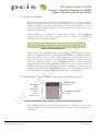
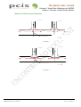
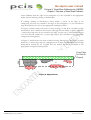
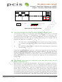
the ukpms user manual
Volume 2
Visual Data Collection for
UKPMS
Chapter 1: Overview of Visual
Data Collection
the ukpms user manual
Volume 2: Visual Data Collection for UKPMS
Chapter1: Overview of Visual Data Collection
Document Information
Title (Sub Title)
Product Number
Author
Description
The UKPMS User Manual
Volume 2: Visual Data Collection for UKPMS
Chapter 1. Overview of Visual Data Collection
UKPMS Manual July 2009
James Wallis
UKPMS Visual Survey Manual
Introductory and Overview Chapter
Document History
Version
No
Status
Author
Date
01
02
03
04
Draft
Draft
Final
Revised
JW
JW
JW
JW
March 05
20 June 05
July 2005
Feb 2007
05
06
07
08
Revised
Review
Revised
Final
JW
JW
KAG
ME
July 2009
Sept 2009
Oct 2009
30 Oct 2009
Changes from Previous Version
First release for internal review
All USG comments incorporated, issued for proof reading
Final for release
Changes in line with new Inspector Accreditation and
recommendations from UKPMS Visual Survey subGroup
Incorporating changes since 2007
Issued for external review
Revised following review
Final for release
PCIS Support Contractor
TRL
Crowthorne House
Nine Mile Ride
Wokingham
Berkshire
RG40 3GA
www.pcis.org.uk
Email: [email protected]
Phone: +44 (0)1344 770480
Fax: +44 (0)1344 770356
UKPMS Manual_02_01v08.doc
October 2009
Page 1 of Chapter 1
the ukpms user manual
Volume 2: Visual Data Collection for UKPMS
Chapter1: Overview of Visual Data Collection
Contents
1
2
3
4
5
6
7
8
9
10
11
12
13
14
15
Who should read this manual?......................................................................................... 3
What is UKPMS? ............................................................................................................... 3
What are the UKPMS Visual Surveys? ........................................................................... 3
What are the UKPMS Visual Surveys used for? ........................................................... 4
Who should carry out UKPMS Visual Surveys? ........................................................... 5
Health and Safety ............................................................................................................... 5
Visual Survey Details......................................................................................................... 6
Network and Location Referencing..............................................................................11
Cross Section Positions ..................................................................................................14
"Not Assessed" and "Not Defective" Features ..........................................................15
Relationship of CVI and DVI Defects .........................................................................16
Surveying Procedures ......................................................................................................21
Frequently asked questions ............................................................................................22
Abbreviations ...................................................................................................................33
Acknowledgements .........................................................................................................34
UKPMS Manual_02_01v08.doc
October 2009
Page 2 of Chapter 1
the ukpms user manual
Volume 2: Visual Data Collection for UKPMS
Chapter1: Overview of Visual Data Collection
1
Who should read this manual?
This manual is intended to provide surveyors and those responsible for auditing
visual surveys with the necessary information to carry out all UKPMS accredited
Visual Inspections accurately and consistently. It will also be of interest and
relevance to managers, engineers and auditors who are responsible for arranging
for surveys to be carried out and who have to interpret or assess the output
produced from those surveys.
2
What is UKPMS?
UKPMS, the United Kingdom Pavement Management System, is a standard for
computer systems that support the management of programmed maintenance of
hard paved areas within the highway, and the monitoring of condition and need for
funding on local authority road networks within the UK. There is no single
UKPMS, but a range of commercial highway management systems have been
tested and accredited as meeting the UKPMS standard.
As well as software, the UKPMS standard also covers the associated survey
techniques, and rules and parameters that allow the systems to be operated in a
consistent, standard way.
3
What are the UKPMS Visual Surveys?
There are three types of UKPMS visual survey.
The Coarse Visual Inspection survey (CVI) is intended to be a simple, rapid survey,
usually carried out from a slow-moving vehicle, that enables a large part of a
highways authority’s road network to be assessed each year. The CVI protocol
includes both carriageways and footways.
The Detailed Visual Inspection survey (DVI) is a more comprehensive survey, with
defects identified by a larger number of more detailed classifications. The DVI is a
walked survey that provides more detailed information and is typically targeted at
lengths already identified as defective and potentially in need of treatment either
from other surveys or other sources of information. The DVI protocol includes
both carriageways and footways.
The Footway Network Survey (FNS) is intended to be a simple, rapid survey of the
footway network. It is a walked survey that enables a large part of a highways
authority’s footway network to be assessed each year. It is intended to be used for
identifying lengths of network which are potentially in need of more detailed
investigation or of treatment.
UKPMS Manual_02_01v08.doc
October 2009
Page 3 of Chapter 1
the ukpms user manual
Volume 2: Visual Data Collection for UKPMS
Chapter1: Overview of Visual Data Collection
For the purposes of this manual, the terms “survey” and “inspection” are used
interchangeably, to denote the type of condition assessment technique, of which
CVI, DVI and FNS are examples, where condition and the need for planned
maintenance schemes are assessed from a visual examination of the paved surfaces
of the road.
It is envisaged that more detailed engineering investigations and surveys would be
carried out before planned maintenance schemes; such surveys are not covered in
this manual.
UKPMS Visual Surveys only include a minimal amount of inventory, collected to
support processing and treatment selection requirements, although the surveys may
be combined with Inventory data (i.e. locations, dimensions and construction of
paved items) to produce more accurate results when processed in a UKPMS
System. Refer to Chapter 5 Inventory in Volume 2 of this UKPMS User Manual.
Some users may find it cost-effective to carry out Inventory data collection at the
same time as a DVI.
4
What are the UKPMS Visual Surveys used for?
In many authorities UKPMS visual surveys have multiple uses in pavement asset
management, typically for
monitoring network condition and performance,
identifying and prioritising schemes and works programmes, and
determining budgetary needs and financial allocations.
Condition surveys are also used to provide financial information for asset
management, such as depreciated replacement cost.
Visual surveys complement machine surveys such as the Deflectograph, SCRIM
and SCANNER on classified roads and are the main source of condition
information on the rest of the network.
Information from visual surveys can be used for internal performance monitoring
and benchmarking between authorities. For example:
To produce internal performance indicators (sometimes referred to as Key
Performance Indicators, KPI).
To inform decisions about how, when and where to carry out maintenance
schemes within an authority, and to support the internal audit of such
decisions.
To support an authority’s Asset Management Plan, including;
Determining a required level of budget and investment over time to
maintain or to achieve a required condition or level of service for a
road network.
UKPMS Manual_02_01v08.doc
October 2009
Page 4 of Chapter 1
the ukpms user manual
Volume 2: Visual Data Collection for UKPMS
Chapter1: Overview of Visual Data Collection
Assessing the future implications of current levels of funding.
Determining the depreciated value of the paved assets in the
network.
5
Who should carry out UKPMS Visual Surveys?
UKPMS surveys are designed to be carried out by staff trained in the relevant
survey techniques, and who are able to record defects accurately and consistently,
in accordance with the definitions and procedures described in this manual.
UKPMS surveyors are not expected to make decisions about the cause of defects,
required treatments or to make other engineering judgements. Objectivity and
consistency are paramount considerations in carrying out visual surveys.
UKPMS accredited surveys may only be carried out by UKPMS accredited
inspectors. An inspector accreditation system, endorsed by the UK Roads Board,
has been in place for a number of years with the support of local highway
authorities and commercial contractors. Further information is provided in
Chapter 2 Inspector Accreditation in Volume 2 of this UKPMS User Manual.
Due to the importance that local highway authorities place on consistent, reliable
condition data collected for planning maintenance, for asset management and for
asset valuation it is recommended that all visual surveys are undertaken by
accredited inspectors.
To ensure that surveys are consistent it is recommended that any staff who manage
surveyors or audit the results from surveys should be trained and accredited to the
same level as the inspectors.
The results from visual inspection surveys are normally recorded using hand held
data capture devices. The software for recording the results should also be
accredited, to ensure consistency and reliability. Further information is provided in
Chapter 3 DCD Software Accreditation in Volume 2 of this UKPMS User Manual.
6
Health and Safety
The following information is only general advice, the surveyor should be made
aware of the contractor’s or highway authority’s own health and safety policy
before they undertake any surveys, including risk assessments, and this must take
precedence over the general advice within this chapter.
Surveyors should report any safety related defect, even where there may be no
specific requirement to do so in the survey being undertaken. The surveyor must
be made aware of the highway authority’s policy on safety related defects and
ensure they know who to contact in case of emergency.
UKPMS Manual_02_01v08.doc
October 2009
Page 5 of Chapter 1
the ukpms user manual
Volume 2: Visual Data Collection for UKPMS
Chapter1: Overview of Visual Data Collection
It is important that surveyors remain alert to the dangers of moving vehicles. To
ensure that surveyors can always be seen, high visibility jackets conforming to BS
EN 471:2003 should be worn at all times, when outside a survey vehicle. Where
possible, surveys on foot should be carried out from the footway or verge. When
measurements are being made on the carriageway (e.g. rut depth) by one surveyor,
the other surveyor should act as a lookout to warn of oncoming traffic.
On dual carriageways and other busy roads with fast moving traffic, traffic
management will normally be required to ensure a safe survey. This should be in
accordance with Chapter 8 of the Department for Transport’s Traffic Signs
Manual.
For CVI surveys, the survey vehicle should be equipped with high intensity roofmounted flashing beacons. As the vehicle will be operating at slow speeds, it is
recommended that the rear of the vehicle should be fitted with a blue arrow sign to
diagram No. 610 of the Traffic Signs Regulations and General Directions 2002,
together with a sign explaining the nature of the work (e.g. "CAUTION SURVEYING IN PROGRESS - SLOW MOVING VEHICLE"). It is preferable
to use a vehicle with a conspicuous colour such as bright yellow or orange. In
planning the survey any traffic sensitive lengths that are best-surveyed at off-peak
times should be identified.
A minimum of two personnel are required for a driven survey, a driver and a
surveyor.
7
Visual Survey Details
7.1 Wheel Track Rutting
Wheel Track rutting is defined as a longitudinal depression in the wheel tracks
relative to the surrounding area. Note that for UKPMS surveys, no distinction is
made between "plastic" rutting, where rutting results from "pushing" of
bituminous material in the upper layer(s) of the pavement and “structural” rutting,
where rutting results from structural deformation in lower layers of the pavement.
Figure 1 “Structural” Wheel Track Rutting
UKPMS Manual_02_01v08.doc
October 2009
Page 6 of Chapter 1
the ukpms user manual
Volume 2: Visual Data Collection for UKPMS
Chapter1: Overview of Visual Data Collection
Figure 2 “Plastic” Wheel Track Rutting
Wheel track rutting can be surveyed manually. For CVI surveys a simple visual
assessment can be undertaken. For DVI surveys a straight edge and calibrated
wedge or depth measure can be used. However, the preferred option, for both
types of survey, is to undertake a machine-based assessment. This is recommended
both on grounds of accuracy, and for DVI surveys, safety since it removes the need
to walk onto the carriageway.
Two special survey types of Machine Collected Rutting for DVI (DRUT) and
Machine Collected Rutting for CVI (CRUT) have been defined to support the
loading and processing of such with visual surveys. Further information on CRUT
and DRUT is provided in Volume 3 “Machine Data Collection for UKPMS” of this
UKPMS User Manual..
More recently, with the development of machine based survey methods, such as
SCANNER, rut depth is measured automatically as part of the survey. Further
information on SCANNER measurements of rut depth is given in Volume 3
“Advice to local authorities – Using SCANNER survey results” of the SCANNER User
Guide and Specification.
Machine rut surveys use the Full Cross Sectional Position (XSP) referencing
convention, separately for each lane. This will still allow Minimal XSP CVI surveys
to be processed with Machine Rut data, although it will require that the DVI survey
be carried out using the Full XSP convention. Further information on the use of
Cross Sectional Position is provided in Chapter 6 Cross Sectional Position (XSP) of
this UKPMS User Manual.
7.2 Features
"Features" within UKPMS are the main paved items that are subject to survey, and
for which condition indices and treatment proposals are produced. The Features
within UKPMS are:
Carriageway
Footway and Footpath
Cycleway and Cyclepath
Paved Verge (Grass verges and other unmade areas are not covered by
UKPMS)
Kerb
Longitudinal Joint in Concrete
Transverse Joint in Concrete
UKPMS Manual_02_01v08.doc
October 2009
Page 7 of Chapter 1
the ukpms user manual
Volume 2: Visual Data Collection for UKPMS
Chapter1: Overview of Visual Data Collection
7.3 Survey Direction
Sections may be surveyed in either a ‘forward direction’ or a ‘reverse direction’.
The terms ‘forward’ and ‘reverse’ are used with respect to the ‘reference direction’
which is defined by the start and end nodes or the section description. On oneway streets and for dual carriageways, the reference direction of the section is the
direction of traffic flow.
Table 1 (below) is an example of a road section reference. The Description
contains the “From” and “To” location. This is referred to as either the
“Forward” or the “Normal” direction”.
Section Label
A/123456/00
Description
James Street From Street A to Street B
Length
300m
Table 1 Section Reference
Upon loading to the UKPMS system, reverse direction surveys will be reversed to
match the normal direction recorded against the section. UKPMS includes a
facility that allows a user to ensure that all surveys are always carried out in the
same direction (i.e. forward or reverse), by recording a "normal surveying
direction" against the section. It is recommended that in all but exceptional
circumstances the normal surveying direction should be set to be the same as the
referenced direction of the section. If a section is labelled as ‘reverse’ then the
UKPMS system will alter the data automatically, i.e. the end chainage will become
the start chainage (0) and the XSP’s will change from L to R and R to L.
7.4 Pavement Type, Surface Type and Construction Type
Pavement
Type -
Bituminous
Surface,
Concrete
Construction
Surface Type
Bituminous
Construction Type
Concrete
Figure 3 Pavement Type, Surface Type and Construction Type
The UKPMS approach for defects and processing is founded on three related
concepts relating to the material from which a pavement under consideration is
constructed.
UKPMS Manual_02_01v08.doc
October 2009
Page 8 of Chapter 1
the ukpms user manual
Volume 2: Visual Data Collection for UKPMS
Chapter1: Overview of Visual Data Collection
The Surface Type is the material from which the visible element of the
pavement is constituted. It is this surface element that is of concern when
undertaking a visual survey.
The Construction Type of a paved feature is the structural element of a
pavement.
The Pavement Type combines the surface and construction elements of the
pavement and has the most important logical role within UKPMS
processing.
Each time a defect is recorded, the defect code will determine the Pavement Type,
which is used to select the rules that are applied during UKPMS processing. This
Pavement Type is based upon both the Surface Type implied by the survey data,
but also any available information about construction held in the inventory, if this
exists (In practice, observations always have a Pavement Type, even if, in the
absence of a paved surface inventory, this is a "default", such as "Bituminous
Surface Unknown Construction). Figure 3 shows this, by way of an example, for
the Bituminous Surface, Covered Concrete Pavement Type.
Table 2 shows all possible Pavement Types, and their related Surface and
Construction Types for the Features covered by UKPMS visual surveys. In many
cases the Surface, Construction and Pavement Types of a feature may be the same.
Feature
Carriageway
Surface Type
Bituminous
Construction
Type
Bituminous
Concrete
Leanmix
Unknown
Block Paved
Concrete
Cycle Track
Footway
UKPMS Manual_02_01v08.doc
Unknown
Bituminous
Block Paved
Concrete
Flagged
Bituminous
Block Paved
Continuously
Reinforced
Concrete
Reinforced
Jointed Concrete
Unknown
Unreinforced
Jointed Concrete
Unknown
Bituminous
Block Paved
Concrete
Flagged
Bituminous
Pavement Type
Bituminous
Covered Concrete
Bituminous Surface,
Leanmix Construction
Bituminous Surface,
Unknown Construction
Block Paved
Continuously Reinforced
Concrete
Reinforced Jointed
Concrete
Concrete Surface,
Unknown Construction
Unreinforced Jointed
Concrete
Unknown
Bituminous
Block Paved
Concrete
Flagged
Bituminous
October 2009
Page 9 of Chapter 1
the ukpms user manual
Volume 2: Visual Data Collection for UKPMS
Chapter1: Overview of Visual Data Collection
Feature
Kerb
Verge
Surface Type
Block Paved
Concrete
Flagged
Unknown
Kerb
Bituminous
Block Paved
Concrete
Flagged
Construction
Type
Block Paved
Concrete
Flagged
Unknown
Kerb
Bituminous
Block Paved
Concrete
Flagged
Pavement Type
Block Paved
Concrete
Flagged
Unknown
Kerb
Bituminous
Block Paved
Concrete
Flagged
Table 2 Surface, Construction and Pavement Types
The Surface Types are as follows:
Bituminous Carriageways
Carriageways with a bituminous depth greater than 20mm at the surface, including
hot rolled asphalt, stone mastic asphalt, dense bitumen macadam and other
bituminous materials, including those with a surface dressing, proprietary thin
surface, or with anti-skid surfacing applied. This includes flexible composite
carriageways (“covered concrete”) with a lean-mix concrete sub-base.
Concrete Carriageways
All carriageways with a concrete surface, including continuously reinforced
concrete (which will have only occasional joints), and concrete constructed in bays
of reinforced or unreinforced concrete. Concrete carriageways that have a surface
dressing or thin bituminous layer on top of them, less than 20mm thick, are also
included.
Block Paved Carriageways
All types of carriageways constructed from small element blocks (including
concrete, cobbles, granite setts, brick and, exceptionally, wooden blocks).
Unknown Surface Carriageways
This category is only used for machine surveys.
Kerbs
All kerb types, including concrete, stone and extruded asphalt.
UKPMS Manual_02_01v08.doc
October 2009
Page 10 of Chapter 1
the ukpms user manual
Volume 2: Visual Data Collection for UKPMS
Chapter1: Overview of Visual Data Collection
Bituminous Footways, Cycleways and Paved Verges
This category includes surface dressed or slurry-sealed features.
Block Paved Footways, Cycleways and Paved Verges
Concrete blocks, brick pavers, granite setts and other small element paving.
Flagged Footways, Cycleways and Paved Verges
Concrete and stone paving flags, including smaller, square modular concrete flags.
Concrete Footways, Cycleways and Paved Verges
Concrete surfaced, with or without joints.
Unknown footways
The FNS uses an "unknown" pavement type in order to make the survey
independent of surface type, although if an inventory exists this will be used when
the surveys are processed within UKPMS.
8
Network and Location Referencing
In a UKPMS accredited system, a road network comprises a spatially located and
uniquely-labelled set of sections of highway, which act as the key for referencing
other related data (including inventory and condition). UKPMS network
referencing is not prescriptive, the intention being that an existing network
referencing system such as those previously used for CHART or MARCH surveys
can be re-used, or that the National Street Gazetteer can form the basis of a
section-based network. Minimising the number of networks used within an
authority helps promote exchange and integration of road related data.
At its simplest UKPMS network referencing requires that the road network is
referenced to a list of unique sections, with some means of deriving a direction
(even if only in the description), as described in section 7.3 “Survey Direction” of this
chapter. Additionally, UKPMS provides the opportunity to introduce nodes, which
unambiguously define direction, and connectivity between sections, and optionally,
shape points, determined by the user. On those parts of the network where
machine surveys, such as SCANNER, are carried out nodes must be used to
identify the start and end points of the sections from which survey direction can be
inferred by the UKPMS system. Further information is provided in Volume 1
Chapter 4 “Network Referencing” of this UKPMS User Manual.
UKPMS network referencing is characterised as follows:
UKPMS Manual_02_01v08.doc
October 2009
Page 11 of Chapter 1
the ukpms user manual
Volume 2: Visual Data Collection for UKPMS
Chapter1: Overview of Visual Data Collection
1.
The road network is divided into sections, each of which is identified
uniquely by a section label. Sections have a designated start and end to
enable specific defects to be located correctly to the left and right hand sides
of the road within a section. Start chainage is always zero. As shown in
Example 1 the sections should run contiguously. This will ensure that
vehicle based surveys are carried out easily and minimises any errors in
processing. This type of potential difficulty is illustrated in Example 2,
where Section “1” is referenced in the opposite direction to Section “0” and
Section “2”.
2.
Location is referenced differently, depending on survey type. CVI and FNS
defects are referenced by start and end chainage within section, and DVI
defects by sub-section start and end chainages. In practice, the DCD software
used for DVI surveys may allow defects to be recorded by actual start and end
chainage, the allocation to sub-sections being handled automatically by the
software. Note that whilst UKPMS makes use of chainage based referencing,
this is not incompatible with the use of co-ordinate based systems such as GPS
and GIS mapping software for data collection, reporting and interaction with
the user, provided that the two systems can be co-related.
3.
None of the following characteristics is permitted to change within a section
(i.e. sections should be homogenous in terms of the following):
Carriageway Construction Type. (In some exceptional cases a road
section may contain different construction types. e.g.: Where a
section on a concrete carriageway includes bituminous construction
at bridge approaches, or within short housing estate cul-de-sacs.)
Number of "Permanent" Lanes
Road Classification
Maintenance Hierarchy, unless this is held as an inventory attribute,
in which case a “default” value will be held for the section.
(Classification used for the allocation of priorities and for the
definition and application of standards for highway maintenance, as
recommended and detailed in the Code of Practice for Highway
Maintenance Management – Well-maintained Highways, Roads
Liaison Group, July 2005)
Environment (i.e. whether it is "Urban" or "Rural")
Speed Limit. (In principle, "Speed Limit" should not change within
a section, as it is used for ranking schemes on the basis of condition.
In practice, the current version of the UKPMS default rules and
parameters does not use this facility, so that it may be possible to
leave this out - you are advised to check with your UKPMS system
supplier before making this decision.)
For all surveys, each carriageway of a dual carriageway is considered separately, and
referenced in the direction of traffic, as are roundabouts, which should always be
surveyed in a clockwise direction. Example 3 and example 4 illustrate these points.
UKPMS Manual_02_01v08.doc
October 2009
Page 12 of Chapter 1
the ukpms user manual
Volume 2: Visual Data Collection for UKPMS
Chapter1: Overview of Visual Data Collection
Network Referencing Examples
(Minor Junction)
(Major Junction)
Section B
Section A
Section 0
Section 1
Section change at junction
Section 2
Shows direction of referencing AND traffic
Example 1
(Major Junction)
(Minor Junction)
Section A
Section 0
Section B
Section 1
Section change at junction
Section 2
Shows direction of referencing NOT Traffic Direction
Example 2
UKPMS Manual_02_01v08.doc
October 2009
Page 13 of Chapter 1
the ukpms user manual
Volume 2: Visual Data Collection for UKPMS
Chapter1: Overview of Visual Data Collection
Section 1
Section 4
Section 3
Section 2
Shows direction of referencing AND traffic
Section 2
Example 3
Section B
Section C
Section 1
Section A
Example 4
9
Cross Section Positions
In addition to locating defects, inventory items, condition indices and indicative
treatments by section and chainage, UKPMS provides a convention to locate items
across the carriageway, using Cross Section Positions (XSP’s). There are two
alternative levels of detail for defining the transverse location of a defect:
Minimal (Simple) Cross Section Positions
Full (Detailed) Cross Section Positions
The level of detail to be used is predetermined before surveying each section,
separately for the carriageway and for the off-carriageway features. Both the
minimal and full options are provided to permit the user flexibility in application,
according to the available resources, the requirements of a particular road hierarchy
and survey type.
UKPMS Manual_02_01v08.doc
October 2009
Page 14 of Chapter 1
the ukpms user manual
Volume 2: Visual Data Collection for UKPMS
Chapter1: Overview of Visual Data Collection
For example, the minimal method, which allocates information to the carriageway
or to the "left" or "right”, would be sufficient for a little used street, where
treatment of individual lanes is unlikely. The full method must be used where lanespecific machine surveys are carried out, and would be appropriate where treatment
of an individual lane is a possibility. (Note that there are proposals to rationalise
Cross Section Position referencing within UKPMS and to remove the distinction
between full and minimal codes)
For the minimal method, generally for CVI and FNS surveys, the transverse
location of a defect will be defined broadly by features:
Carriageway
Left and Right Kerb
Left and Right Footway/Cycletrack/Verge.
In the case of Footways and Cycletracks that are not associated with a carriageway,
they should be recorded on the Left.
For the full method, the cross section position is a code representing a physical
band across the highway, e.g. a traffic lane, a footway or a verge.
For each section on the UKPMS network, the XSP method that should be used is
recorded, separately for the Carriageway and for the Off-Carriageway Features. All
surveys that are carried out on that section/feature must use the nominated XSP
method, with the exception of CVI surveys, which can always be carried out using
the minimal method. Further information on the use of Cross Sectional Position is
provided in Chapter 6 Cross Sectional Position (XSP) of this UKPMS User Manual.
10
"Not Assessed" and "Not Defective" Features
UKPMS provides for two "special" defects, for all surface types and features; "Not
Assessed" and "Not Defective". "Not Assessed" means that although the recorded
feature exists (for the chainage range and cross-section position recorded) it has
not been inspected. This could either be intentionally, for example when a
"Partial" survey is being carried out, or unintentionally, where for example road
works or parked vehicles prevent the survey of a particular feature or section.
"Not Defective" is only recorded for features and cross section positions where
there are no "real" defects recorded on a section. "Not Defective" shows that
although the feature has been inspected, it is free from reportable defects.
Recording "Not Defective" means that areas that are in good condition are
included in reports on the condition of road network, and can be used to "project"
future conditions.
Before carrying out a survey, you need to know whether that survey will be used
for Condition Projection that is, to determine future condition to support future
budgeting and to allocate priorities on the basis of the consequences of not
UKPMS Manual_02_01v08.doc
October 2009
Page 15 of Chapter 1
the ukpms user manual
Volume 2: Visual Data Collection for UKPMS
Chapter1: Overview of Visual Data Collection
carrying out treatments. If so, recording of "Not Defective" for all features and
cross section positions that exist would be desirable but it places considerable
overheads on the UKPMS survey.
Taking this into consideration it is
recommended that “Not Defective” is not recorded as part of the UKPMS visual
surveys, unless the user of that survey identifies a clear need for explicit recording
of lengths that have no defects.
For minimal XSP surveys of footways, cycletracks, paved verges and kerbs, “Not
Defective” and/or “Not Assessed” should be recorded separately for each side (i.e.
Left and Right) for which the feature exists.
For the FNS, condition category one ("as new") indicates those parts of the section
that have been surveyed but have no reportable defects and therefore there is no
need for the special defects “not defective” and “not assessed”. Further
information on the Footway Network Survey is provided in Chapter 9 Footway
Network Survey of this UKPMS User Manual.
11
Relationship of CVI and DVI Defects
The following tables show the relationships between CVI and DVI and between
DVI and FNS defects. The results from DVI surveys can be converted into CVI
and FNS surveys, therefore there needs to be a comparison between the defects
which these tables show.
UKPMS Manual_02_01v08.doc
October 2009
Page 16 of Chapter 1
the ukpms user manual
Volume 2: Visual Data Collection for UKPMS
Chapter1: Overview of Visual Data Collection
Feature
All
Surface Type
All
Carriageway
Bituminous
Block Paved
UKPMS Manual_02_01v08.doc
DVI Defect
CVI Defect
Not assessed
Not defective
WC major cracking
WT major cracking
Transverse/Reflection cracking – Severity 1
Transverse/Reflection cracking – Severity 2
WC minor fretting
WC major chip loss
WC major fatting
WC minor chip loss
WC minor fatting
WC minor cracking
WC major fretting
Severe Local Settlement/Subsidence
Moderate Local Settlement/Subsidence
Left Recorded Edge deterioration Severity 1
Left Recorded Edge deterioration Severity 2
Right Recorded Edge deterioration Severity 1
Right Recorded Edge deterioration Severity 2
WT rutting
WT Rutting
Severe Block Deterioration
Moderate Block Deterioration
Damaged Blocks
Misaligned Blocks
Missing Filler
Not assessed
Not defective
CVI Wearing Course
CVI Transverse/Reflection
Cracking
CVI Surface deterioration
Not Recorded for CVI
CVI Wearing Course
CVI Settlement/subsidence
Not Recorded for CVI
Left Recorded CVI Edge
deterioration
Right Recorded CVI Edge
deterioration
CVI Rutting
CVI Rutting
CVI Block Deterioration
CVI
Minor
Deterioration
Not Recorded
Block
October 2009
Page 17 of Chapter 1
the ukpms user manual
Volume 2: Visual Data Collection for UKPMS
Chapter1: Overview of Visual Data Collection
Feature
Surface Type
Concrete
DVI Defect
CVI Defect
Transverse Defective Seal
CVI Transverse Defective
Seal
CVI Longitudinal Defective
Seal
CVI
Transverse
Joint
Defectiveness
Carriageway
Longitudinal Defective Seal
Kerb
All Materials
Major Transverse Joint Spalling
Minor Transverse Joint Spalling
Transverse Joint Faulting
Transverse Joint Cracking
Major Longitudinal Joint Spalling
Minor Longitudinal Joint Spalling
Longitudinal Joint Faulting
Longitudinal Joint Cracking
Minor Concrete Surface Deterioration
Major Concrete Surface Deterioration
Local Settlement
Global Settlement
Minor Single Cracking*
Major Single Cracking*
Multiple Cracking
Bituminous Patching
Inadequate Upstand
Kerb Disintegration
*Cracking defects have a "direction" parameter
indicating whether they are longitudinal or transverse
CVI Longitudinal Joint
Defectiveness
CVI
Concrete
Deterioration
CVI Settlement
Surface
CVI Concrete Cracking
CVI Bituminous Patching
Inadequate Upstand
Kerb Deterioration
Table 3 Relationship between CVI and DVI Defects - Carriageway
UKPMS Manual_02_01v08.doc
October 2009
Page 18 of Chapter 1
the ukpms user manual
Volume 2: Visual Data Collection for UKPMS
Chapter1: Overview of Visual Data Collection
Footway, Cycletrack and Paved Verge
Feature
Surface Type
DVI Defect
CVI Defect
Bituminous
Major Cracking
Major Fretting
Severe Local Settlement/Subsidence
Moderate Local Settlement/Subsidence
Spot Defects
Longitudinal Trip
Minor Cracking
Minor Fretting
Major Cracking
Major Scaling/Fretting
Severe Local Settlement/Subsidence
Moderate Local Settlement/Subsidence
Spot Defects
Longitudinal Trip
Minor Cracking
Minor Scaling/Fretting
Cracked and Depressed Flags
Depressed Flags (not Cracked)
Spot Defects
Longitudinal Trip
Cracked but Level Flags
Cracked and Depressed Blocks
Depressed or Missing Blocks
Spot Defects
Longitudinal Trip
Damaged Blocks
Missing Filler
Major Bituminous
Deterioration
Concrete
Flagged
Block Paved
Minor Bituminous
Deterioration
Major Concrete
Deterioration
Minor Concrete
Deterioration
Major Flagged Deterioration
Minor Flagged Deterioration
Major Block Deterioration
Minor Block Deterioration
Not Recorded
Table 4 Relationship between CVI and DVI Defects – Footway
UKPMS Manual_02_01v08.doc
October 2009
Page 19 of Chapter 1
the ukpms user manual
Volume 2: Visual Data Collection for UKPMS
Chapter1: Overview of Visual Data Collection
Footway, Cycletrack and Paved Verge
Feature
Surface Type
DVI Defect
FNS Defect
Bituminous
Major Cracking
Major Fretting
Severe Local Settlement/Subsidence
Moderate Local Settlement/Subsidence
Spot Defects
Longitudinal Trip
Minor Cracking
Minor Fretting
Major Cracking
Major Scaling/Fretting
Severe Local Settlement/Subsidence
Moderate Local Settlement/Subsidence
Spot Defects
Longitudinal Trip
Minor Cracking
Minor Scaling/Fretting
Cracked and Depressed Flags
Depressed Flags (not Cracked)
Spot Defects
Longitudinal Trip
Cracked but Level Flags
Condition Category 4
(Structural Unsound)
Concrete
Flagged
Block Paved
Cracked and Depressed Blocks
Depressed or Missing Blocks
Spot Defects
Longitudinal Trip
Damaged Blocks
Missing Filler
Condition Category 3
(Functionally Impaired)
Condition Category 4
(Structural Unsound)
Condition Category 3
(Functionally Impaired)
Condition Category 4
(Structural Unsound)
Condition Category 3
(Functionally Impaired)
Condition Category 4
(Structural Unsound)
Condition Category 3
(Functionally Impaired)
Table 5 Relationship between FNS and DVI Defects - Footway
UKPMS Manual_02_01v08.doc
October 2009
Page 20 of Chapter 1
the ukpms user manual
Volume 2: Visual Data Collection for UKPMS
Chapter1: Overview of Visual Data Collection
12
Surveying Procedures
12.1
Recording defects
Defects must be recorded as stated within this manual or any future advice notes
which may be issued from the PCIS Support Contractor. Each defect must be
recorded accurately, for area and location. If multiple defects exist within the same
area, each defect is to be recorded separately. The surveyor MUST NOT record
what he/she thinks is the worst defect. The exception to this practice is for FNS
surveys, where only one condition category can be recorded at any point along a
footway. In cases where more than one condition category exists across the width
of a footway, then the "worst" category is taken as representative, and the total
extent of all conditions is applied to that category, where extent is being recorded.
12.2
Auditing
At present there are no national rules for auditing visual survey data. It is
important that you take ownership of this data and you consider having your own
audit regime. Guidance on auditing is provided in Chapter 4 QA & Audit in
Volume 2 of this UKPMS User Manual. . (www.pcis.org.uk)
12.3
Survey direction
It is important the surveyor records the direction of survey in relation to the
direction of the section referencing. If the survey is taking place in the opposite
direction to the referencing then the survey MUST be marked as REVERSE.
12.4
Correct inventory
If you have full inventory within your system, the system will look up the inventory
table and process the data against this. Therefore it is important that when carrying
out a visual survey you record the defects in the correct cross-sectional position.
12.5
Machine surveys
When carrying out machine surveys, your system MUST be set up as having full
cross-sectional positions on the carriageway. This means that if you plan to use
minimal XSP CVI data on the same section you MUST have carriageway inventory
information in the form of lane widths and lengths.
UKPMS Manual_02_01v08.doc
October 2009
Page 21 of Chapter 1
the ukpms user manual
Volume 2: Visual Data Collection for UKPMS
Chapter1: Overview of Visual Data Collection
Frequently asked questions
13
Q1.
Can I mix Full and Minimal XSP surveys on the same section?
The Normal XSP Method is set separately for the carriageway and for the offcarriageway features, for each section on the network. All surveys on that section for the
carriageway and for the other features should use the set method with one exception irrespective of the XSP method set. Minimal method CVI surveys can be carried out.
For example, if the XSP method for the Carriageway is set as "Detailed" although DVI
and Machine surveys must use the Detailed XSP method, you can still carry out Minimal
method CVI surveys. (Note that if you wish to process Minimal CVI data and full XSP
data from other surveys together, a full XSP inventory must have been collected.
Proposals to simplify XSP referencing are likely to change these provisions in the
future.)
Q2.
Can I carry out the surveys using paper forms?
You cannot report surveys using paper forms if the survey is to be used for performance
reporting. It may be viable to carry out very small-scale surveys using paper forms, for
audit or training purposes. You should use electronic Data Capture Devices (DCD)
together with appropriate accredited software for UKPMS visual surveys. Further
information is provided in Chapter 3 DCD Software Accreditation in Volume 2 of this
UKPMS User Manual. Details of accredited DCD software suppliers are given on the
PCIS web site, www.pcis.org.uk.
Q3. I have two separate footways on the same side of the section. Do I have to use
Full XSP referencing to survey them?
It is recommended that you use full XSP referencing in this situation for DVI surveys.
But if you wish you can treat one of the footways as a paved verge (verges have the same
defects, processing rules and associated standards as footways within UKPMS) and then
you will be able to identify them separately. Note also that the footway classified as a
paved verge will not be used in the calculation of BV187. For CVI and FNS surveys
using the Minimal XSP method, they will be treated as if they were a single footway,
which could lead to confusion or inaccuracy if their condition varies, or if they are of
different construction.
Q4. Should cracks that have been sealed be recorded?
Sealed transverse and reflective cracks are not classed as defective within UKPMS.
However, Wheel Track Cracking and Whole Carriageway Major Cracking on bituminous
surfaced carriageways should still be recorded even if they have been sealed.
Q5. How are edge defects that extend into trafficked areas of the carriageway
recorded?
Edge defects should only be recorded in locations where there is no kerb, channel
blocks or other edge restraint. For cracking, fretting or deformation to be classified as
edge deterioration, it must extend to the edge of the carriageway. If it extends beyond ½
UKPMS Manual_02_01v08.doc
October 2009
Page 22 of Chapter 1
the ukpms user manual
Volume 2: Visual Data Collection for UKPMS
Chapter1: Overview of Visual Data Collection
metre (500mm) from the edge of the carriageway it is also recorded as the appropriate
defect, such as cracking, fretting or deformation.
If cracking, fretting or deformation occurs within ½ metre of the edge of the
carriageway, but does not extend to the edge of the carriageway, it is not recorded as
edge deterioration, but only as the appropriate carriageway defect.
In Figure 4, which shows four areas of major fretting, A and B are recorded as edge
deterioration, but C and D are not because, although they are wholly or partly within the
½ metre edge strip, they do not extend to the edge. In this case, C and D plus that part
of A that extends outside the ½ metre edge strip is also recorded as the appropriate
carriageway fretting defect.
In Figure 5, which shows four areas of major fretting, although they are wholly or partly
within the ½ metre edge strip, the carriageway has an edge restraint and therefore edge
deterioration should not be recorded but the defects should be recorded as the
appropriate carriageway fretting defect.
500
Cway Edge
No Kerb or
Channel
B
C
D
A
Figure 4 Edge Defects
UKPMS Manual_02_01v08.doc
October 2009
Page 23 of Chapter 1
the ukpms user manual
Volume 2: Visual Data Collection for UKPMS
Chapter1: Overview of Visual Data Collection
500
Kerb or Channel
B
C
D
A
To be recorded as whole carriageway defect i.e. cracking, fretting etc.
Figure 5 Edge Defects
Q6. What are "Lane Length" defects?
For both DVI and CVI surveys there are a number of defects where the lane length of
the defect is required. For CVI surveys these defects (CVI Wheel Track Cracking) are
recorded according to the number of lanes affected. For DVI surveys the “lane length
affected” in linear metres is recorded for Wheel Track Cracking. For the defect to be
present, there merely has to be some wheel track cracking in either or both of the wheel
tracks. The total possible length within a sub-section will depend upon the cross-section
position referencing method being used; using the Full XSP method the total possible
lane length is the length of the sub section, whereas using the minimal XSP method, the
total possible lane length is the length of the sub-section multiplied by the number of
lanes present on the carriageway at that point.
As an example, in Figure 6, the length between 0 to 40 on the left hand lane, and between
80 and 100 both lanes are affected by wheel track cracking. Using the minimal XSP
method with 20m sub-sections, the maximum length that can be recorded for each subsection is 40m (i.e. sub-section length x no. of lanes). 20m of wheel track cracking is
recorded for each of the first 2 sub-sections, and 40m is recorded for the final subsection. Remember that the Area of the cracking is also recorded as Whole Carriageway
Major cracking in DVI surveys and Wearing Course Deterioration in CVI surveys.
UKPMS Manual_02_01v08.doc
October 2009
Page 24 of Chapter 1
the ukpms user manual
Volume 2: Visual Data Collection for UKPMS
Chapter1: Overview of Visual Data Collection
0m
20m
40m
Major Cracking
80m
90m
100m
Wheel Track Cracking
Wheel paths
Figure 6 Lane Length Defects
Q7. Can video techniques be used for recording UKPMS visual survey data?
You should not attempt to record defects from video surveys if the survey is to be used
for performance reporting or benchmarking.
A number of authorities have
experimented with using digital video surveys to carry out CVI surveys, transcribing the
data manually from the video after the survey, as if carrying out a “virtual” CVI. In
principal, this approach is acceptable if:
The same level of detail is achieved as from a driven survey (image resolution,
no. of cameras and frequency of image capture being the determining factors),
and
The standard CVI procedure is adopted when transcribing the observations
from the video.
Indeed, provided that equivalent accuracy is achieved, this approach has the advantage of
being more auditable and less dependent upon weather conditions. The video survey can
also be used for other applications, such as inventory. It is recommended that if this
approach is adopted, it is trialled on a small sample so that its accuracy can be determined
before data on the whole network is extracted. This approach is not recommended for
DVI surveys.
Q8. Can UKPMS visual surveys be carried out at the same time as other surveys?
(Safety, Streetworks etc.)
This approach is not generally recommended. The intention of condition assessment
surveys such as CVI, DVI and FNS is to assess overall condition and need for treatment,
whereas safety, defect and trench surveys focus on individual defects and issues together
with localised remedial works. The risk of combining surveys is that defects may be
missed, with the surveyor concentrating on too many separate items. Moreover, UKPMS
surveys require the surveyor to be able to record accurately and methodically according to
the definitions within this manual, but do not require the additional skills and knowledge
of materials and maintenance techniques required to undertake defect surveys or surveys
of streetworks and reinstatements. Research carried out by TRL when developing the
UKPMS Manual_02_01v08.doc
October 2009
Page 25 of Chapter 1
the ukpms user manual
Volume 2: Visual Data Collection for UKPMS
Chapter1: Overview of Visual Data Collection
FNS survey found that it was not practicable or effective to carry out the FNS survey in
conjunction with streetworks inspection.
Q9. Can short lengths or small areas of defects be ignored?
All defects that are defined in this manual should be observed and recorded (where
present) because UKPMS surveys are used to determine the condition of the whole
network, and are “projected” to assess future condition and need for treatment and
funding. Even seemingly insignificant defects that would not be treated should be
included.
Q10. Do I have to inspect the whole section when I carry out a CVI, r DVI or FNS
Survey?
No. Partial surveys are permitted for UKPMS surveys. You will however need to start
chainage recording at the start of the section to determine the chainage at which the
survey starts. For CVI and DVI surveys you will also have to record “Not Assessed” for
the chainage lengths where the survey is not being carried out. This is illustrated in
Figure 7. .
Footway
Paved Verge
Kerb
Carriageway
Kerb
Footway
Cycletrack
300m
200m
100m
0m
“Not Assessed”
Survey
“Not Assessed”
(All Features that Are Present)
100 to 200m
(All Features that Are Present)
Figure 7 Partial Surveys by Chainage
Q11. Do I have to inspect all paved features when I carry out a CVI or DVI?
No. Partial surveys by feature are permitted. You will need to record “Not Assessed” for
the whole section for those features that exist on the section but which are not being
inspected. Refer to Figure 8.
UKPMS Manual_02_01v08.doc
October 2009
Page 26 of Chapter 1
the ukpms user manual
Volume 2: Visual Data Collection for UKPMS
Chapter1: Overview of Visual Data Collection
Footway
Paved Verge
Kerb
Carriageway Survey 0m to 300m
Carriageway
Kerb
Footway
Cycletrack
300m
0m
“Not Assessed” 0 to 300m
Left Footway and Cycletrack
Right Footway and Paved Verge
Figure 8 Partial Surveys by Feature
Q12. Why are sections that are clearly not in need of treatment inspected?
UKPMS surveys are used to assess the condition of the whole of an authority’s network,
and are projected forward to assess future condition and need for treatment. It is
important that even sections with little or no deterioration are included to ensure a
complete, accurate assessment. This information is important for asset valuation
purposes.
Q13. How is a "polished" carriageway surface recorded?
For CVI surveys, a severely polished surface, with minimal texture similar to that
occurring where there is major “fatting up” of bituminous binder is recorded as "CVI
Surface Deterioration" for bituminous carriageways and as "CVI Concrete Surface
Deterioration" for concrete carriageways. For DVI surveys, polishing is recorded on
bituminous surfaced carriageways either as Minor Fatting, where there is some surface
texture remaining, or as Major Fatting, where there is no surface texture. Polished
concrete carriageways are recorded using the "Loss of Texture" defect on DVI Surveys.
Q14. Are channel blocks inspected?
Channel blocks are inspected as kerbs, except that “Inadequate Up-stand” is only
recorded if they are sunken below the level of the carriageway.
Q15. Are dropped kerbs for vehicle access assessed for "inadequate up-stand"?
Dropped kerbs are only recorded as having “Inadequate Up-stand” if they are flush with
or lower than the carriageway surface.
UKPMS Manual_02_01v08.doc
October 2009
Page 27 of Chapter 1
the ukpms user manual
Volume 2: Visual Data Collection for UKPMS
Chapter1: Overview of Visual Data Collection
Q16. Can footpaths and cycle paths that are "remote" (i.e. not associated with a
carriageway) be inspected?
Yes. These are normally referenced as separate sections and only have defects recorded
for the footway or cycleway. There is a “special” road hierarchy in UKPMS of “9” ("No
Carriageway") for such sections.
Q17. How are patches and public utility reinstatements assessed?
Patches and public utility reinstatements are inspected as an integral part of the
carriageway or footway. Defects contained in patches and reinstatements are recorded
accordingly. Where UKPMS surveys differ from some other survey types (e.g. CHART)
is that non-defective patches and reinstatements are not recorded as defects.
Q18. Where there is a central reserve between two sections of a dual carriageway, how
is it assessed?
UKPMS uses the convention of identifying one of the two opposite sections as the
“nominated” section to which the “shared” features are referenced. You should make
sure you check which sections are the nominated sections before carrying out a UKPMS
survey of a dual carriageway.
Q19. Can I define my own UKPMS Surveys?
UKPMS allows users to define their own custom survey types and defects, and to define
associated rules for rating, selecting and prioritising treatments, and for assessing need
and likely future conditions and performance. As the definition of custom rules can
prove complex and onerous, most users are likely to use the standard "default" set of
surveys and rules (at least until they have gained experience in the use of UKPMS).
Moreover, if surveys are being carried out to support the production of performance
indicators, or used to make comparisons between different authorities on a consistent
basis, then you will have to use the standard surveys and associated rules.
If you do wish to define custom surveys, defects and rules then it is suggested that you
do so by adding local defects to the standard survey, in order that you will still be able to
produce the performance indicators and other standard outputs. Alternatively, a new
survey can be created by incrementally changing the default surveys and rules, rather than
starting from scratch. Advice should be sought from the PCIS Support Contractor if in
any doubt.
Q20. What is the logic behind the CVI and DVI defect codes?
For off-carriageway defects, there are three components to the defect codes. The first
letter of the code denotes the Feature (Footway, cYcleway, Verge). The second letter
denotes the Surface Type (blocK, Concrete, Flag, and Bituminous). The third letter
denotes the severity of the defect (Major, miNor), and the final letter denotes the
UKPMS Manual_02_01v08.doc
October 2009
Page 28 of Chapter 1
the ukpms user manual
Volume 2: Visual Data Collection for UKPMS
Chapter1: Overview of Visual Data Collection
particular defect. For example, VFMD is the code for "Major Flagged Deterioration" on
a flag paved verge.
For carriageways, the first letter denotes the surface type (blocK paved, Concrete,
Bituminous), with the remaining letters identifying the defect. Where there are major and
minor versions of the defect, the final letter denotes this (Major, miNor) and where there
are two severities this is identified by the last character (1 or 2). For example, BTC2 is
the code for “Transverse/Reflection Cracking – Severity Level 2” on a bituminous
surfaced carriageway.
Q21. How are footway crossings inspected?
In DVI and CVI surveys, footway crossings (vehicle accesses over the footway or
cycleway, often of a different surface type to the footway) are inspected either as part of
the footway or optionally as short lengths of paved verge. This may mean that defects
for the different surface types are being recorded at the same location. For FNS surveys,
there is no need to stop and start defects when surface types change, unless there is a
change of condition, and therefore observations can continue through footway crossings
if appropriate.
Q22. I already have an Inventory collected using RMMS Cross-Section Positions. Can
this be used for UKPMS?
The XSP codes used for RMMS and for UKPMS are different, and the RMMS codes
cannot be converted to the UKPMS codes with complete accuracy. If you are prepared
to undertake some manual updating, it may be possible to carry out the conversion to an
acceptable level of accuracy, particularly on parts of the network with simple
configuration of lanes and features. Conversion from RMMS XSP to minimal UKPMS
XSP is more reliable than conversion to the Full XSP.
Although procedures and programs can be written for converting RMMS inventory data
to UKPMS cross-sectional positions, a number of anomalies exist which can only be
resolved by user intervention. Some of the issues involved are:
The RMMS carriageway inventory item does not include lane referencing. However,
each section is designated as having a number of lanes and also whether it is a single
or dual carriageway. An initial estimate could therefore be made for UKPMS lane
referencing. The conversion could not take account of one-way streets (which are
not differentiated from two-way single carriageways in RMMS) or additional lanes
(which are not recorded in RMMS). Changes due to additional lanes (e.g. crawler
lanes) should, however, be identified in the network data as they would necessitate a
new CHART section because of the change in road type (e.g. from single two-lane
to single three-lane).
RMMS has only three off-carriageway cross-sectional positions for each side; Inner
Verge, Footway and Outer Verge. Interrogation of the footway and verge inventory
itself could make conversion reasonably accurate in the situation where there are
actually no more than two verges separated by a single footway.
UKPMS Manual_02_01v08.doc
October 2009
Page 29 of Chapter 1
the ukpms user manual
Volume 2: Visual Data Collection for UKPMS
Chapter1: Overview of Visual Data Collection
RMMS uses a left-hand rule for items on the margin of two cross-sectional
positions, whereas UKPMS assigns such items to the outer cross-sectional position.
RMMS also refers to the theoretical cross-sectional positions which may not actually
exist. Conversion of such items will depend upon the number of lanes, type of
carriageway and actual existence of footways and verges. Initial rules for each
situation can be defined. It will not, however, be possible to accommodate RMMS
cross-sectional positions Q, W, E, R, T and Y which have no indication of their
physical location with respect to the other cross-sectional positions. These features
of the RMMS method also cause problems with reversing the direction of data.
The relationship between RMMS and UKPMS cross-sectional positions is shown in
Table 6 for single carriageways and Table 7 for dual carriageways respectively.
UKPMS Manual_02_01v08.doc
October 2009
Page 30 of Chapter 1
the ukpms user manual
Volume 2: Visual Data Collection for UKPMS
Chapter1: Overview of Visual Data Collection
RMMS XSP Description
Left Outer Verge
Left Footway
Left Inner Verge
Left Kerb
Left Turning/Acceleration
Lane
Left Lane 1
Right Lane 1
Right Turning/Acceleration
Lane
Right Kerb
Right Inner Verge
Right Footway
Right Outer Verge
RMMS
XSP
UKPMS
Full XSP
UKPMS
Simple XSP
1
2
3
L
W
L3
L2
L1
LE
-L1
4
5
E
CL1
CR1
-R1
C
8
9
0
RE
R1
R2
R3
R
Table 6 Single Carriageway
RMMS XSP Description
Left Outer Verge
Left Footway
Left Inner Verge
Left Kerb
Left
Turning/Acceleration Lane
Left Lane 1
Left Lane 2
Left Lane 3
Right
Turning/Acceleration Lane
Right Kerb
Central Reserve (on the
“nominated” section)
RMMS
XSP
UKPMS
Full XSP
UKPMS
Simple XSP
1
2
3
L
W
L3
L2
L1
LE
-L1
4
5
6
E
CL1
CL2
CL3
+L1
C
8
RE
R1
R
Table 7 Dual Carriageway
Q23. How are grassed verges inspected?
The UKPMS system only covers paved areas; therefore grassed verges cannot be
assessed, and are collected with inventory for information purposes only.
UKPMS Manual_02_01v08.doc
October 2009
Page 31 of Chapter 1
the ukpms user manual
Volume 2: Visual Data Collection for UKPMS
Chapter1: Overview of Visual Data Collection
Q24 Do I record “Not Defective” on a road section for all XSP’s during CVI and DVI
surveys?
You should record “Not Defective” for the whole section for all the XSP’s which are
surveyed but have no defects recorded against them.
Figure 9 shows a section which has been surveyed using full XSP. “Not Defective” does
not need to be recorded for CR1, because there are defects present, but should be
recorded for CL1 as there are no defects present.
Figure 10 shows a section which has been surveyed using simple XSP. “Not Defective”
does not need to be recorded for C, because there are defects present.
CL1
CR1
Section 1
Figure 9 Full XSP
C
Section 1
Figure 10 Minimal XSP
UKPMS Manual_02_01v08.doc
October 2009
Page 32 of Chapter 1
14
Abbreviation
HMDIF
DCD
XSP
UKPMS
NRMCS
RMMS
CVI
FNS
DVI
RBAG
WGA
DRC
TWCS
UKPMS Manual_02_01v08.doc
Abbreviations
Description
Highways Maintenance Data Interchange Format
Data Capture Device
Cross Section Position
United Kingdom Pavement Management System
National Road Maintenance Condition Survey
Routine Maintenance Management System
Coarse Visual Inspection
Footway Network Survey
Detailed Visual Inspection
Roads Board Advisory Group
Whole of Government Accounts
Depreciated Replacement Cost
Thin Wearing Course System
October 2009
Page 33 of Chapter 1
15
Acknowledgements
Project Sponsor – Department for Transport
Pavement Condition Management Group, Chair Chris Capps – Cambridgeshire County Council.
We would like to thank the members of the former UKPMS Visual Survey Sub Group and
members of the UKPMS Support team for their technical advice and assistance. Particular support
was provided by:
UKPMS Manual_02_01v08.doc
Name
Company
Simon Burrows
Scott Wilson
Ruth Aitken
Clowes
Scott Wilson
Simon Phillips
Yotta
Ian Butler
WDM
Andrew Ellingham
TFL
Les Hawker
TFL
Hen Abbott
Jacobs
Contact Details
October 2009
Page 34 of Chapter 1