1
MORLEY-IAS
ZX2E/ZX5E Fire Alarm Control Panels
Table of Contents
1
INTRODUCTION ......................................................................................................................... 5
1.1
1.2
1.3
1.4
NOTICE .................................................................................................................................. 5
WARNINGS AND CAUTIONS ...................................................................................................... 5
NATIONAL APPROVALS ............................................................................................................ 6
EN54 INFORMATION ............................................................................................................... 6
2
UNPACKING............................................................................................................................... 8
3
INSTALLATION .......................................................................................................................... 9
3.1
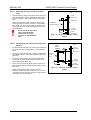
INSTALLING THE ENCLOSURE .................................................................................................. 9
3.1.1
Removing the Chassis .................................................................................................. 9
3.1.2
Mounting the Enclosure to the Wall .............................................................................. 9
3.1.3
Remounting the Chassis............................................................................................... 9
3.2
DIMENSIONS AND FIXING POINTS ........................................................................................... 10
3.3
IDENTIFICATION OF PARTS..................................................................................................... 11
3.3.1
CPU Board .................................................................................................................. 12
3.3.2
Display / Keyboard...................................................................................................... 12
3.3.3
Base Card ................................................................................................................... 12
3.3.4
Zone Extender Card (ZX5E Option Only) ................................................................... 12
3.3.5
Internal Printer (ZX5E Option Only) ............................................................................ 12
3.4
EXTERNAL CONNECTIONS ..................................................................................................... 13
3.4.1
Mains Power Input ...................................................................................................... 13
3.4.1.1
3.4.1.2
3.4.1.3
3.4.2
3.4.2.1
3.4.2.2
3.4.2.3
3.4.2.4
3.4.3
3.4.3.1
3.4.3.2
3.4.3.3
3.4.4
3.4.5
3.4.6
3.4.7
3.4.7.1
3.4.7.2
3.4.7.3
3.4.8
3.4.9
3.4.9.1
3.4.9.2
3.4.9.3
3.4.9.4
ZX1E / ZX2E Arrangement.................................................................................................... 13
ZX5E Arrangement ...............................................................................................................13
Mains Cable Glands .............................................................................................................. 14
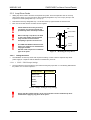
Battery Installation ...................................................................................................... 15
General Introduction.............................................................................................................. 15
ZX1E / ZX2E Arrangement.................................................................................................... 15
ZX5E Arrangement ...............................................................................................................16
General Battery Connection .................................................................................................. 16
Detection Loops .......................................................................................................... 17
Loop Wiring Installation ......................................................................................................... 18
EMC Compliance .................................................................................................................. 19
Panel Loop Loading .............................................................................................................. 19
Sounder Circuits.......................................................................................................... 20
Auxiliary Relay Outputs............................................................................................... 22
Auxiliary Supply Output............................................................................................... 23
Panel Networking / Graphics PC Interface ................................................................. 24
Local Panel Network ............................................................................................................. 24
Master Panel to Superior Master Panel ................................................................................ 24
Panel to Graphics PC............................................................................................................ 24
Peripheral Loop........................................................................................................... 25
RS485 Wiring Arrangements ...................................................................................... 26
Daisy Chain Style Installation................................................................................................ 26
Loop Style Installation ........................................................................................................... 26
EMC Compliance .................................................................................................................. 26
Cable Screen – Earth Connections ....................................................................................... 27
3.4.10 High Integrity Loop...................................................................................................... 27
3.4.11 Group Disable Input .................................................................................................... 27
3.4.12 Class Change Input .................................................................................................... 27
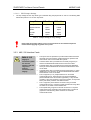
3.4.13 Recommended Cables ............................................................................................... 28
3.4.14 Base Card Power Supply Connections....................................................................... 28
3.4.15 Cable Routing ............................................................................................................. 29
3.5
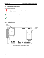
INSTALLING ADDITIONAL EQUIPMENT ..................................................................................... 30
3.5.1
General Introduction ................................................................................................... 30
3.5.1.1
3.5.1.2
3.5.1.3
Page 2 of 46
ZX1E Arrangement ...............................................................................................................30
ZX2E Arrangement ...............................................................................................................31
ZX5E Arrangement ...............................................................................................................31
Document No. 996-131, Revision: 01,
Installation Manual