1
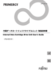
Total Hp
<20m
<50m
Total Hp
<20m
<50m
8
10
12
14
16
18
20
22
24
26
28
30
32
34
36
10
25
10
16
25
25
25
70
70
70
25
25
25
35
35
35
35
70
70
70
70
70
70
70
70
38
40
42
44
46
48
50
52
54
56
58
60
62
64
95
95
95
95
95
35
35
35
35
50
50
50
50
70
70
70
95
95
Indoor power supply
Single-phase 220V~ 50Hz
Leakage protector
Manual switch
1
95
120
120
120
120
120
120
120
120
95
95
95
95
95
95
Branch box
2
3
4
5
6
7
8
Indoor unit
9
10
11
12
13
14
CAUTION
1. Set refrigerant piping system, signal wires between
indoor-indoor unit, and that between outdoor-outdoor unit
into one system.
2. Please do not put the signal wire and power wire in the
same wire tube; keep distance between the two tubes.
(Current capacity of power supply: less than 10A--300mm,
Select the capacity of manual switch and fuse of the branch box.
less than 50A--500mm.)
(1) See following table when without power facilities,
3. Make sure to set address of outdoor unit in case of parallel
depends on the outdoor unit it connecting to.
multi-outdoor units.
(2) See table below when there is power facility,
depends on the total horsepower.
Signal wire of indoor/outdoor unit adopts 2-core
shielded wire ( 0.75mm2 )which has polarity, please
connect it correctly.
Signal wire of indoor/outdoor units
Total horsepower, capacity of manual switch and fuse(table below)
Outdoor unit Outdoor unit Outdoor unit Outdoor unit
Manual Fuse(A) Total Hp Manual Fuse(A)
Total Hp
switch (A)
switch (A)
10~14
15~18
19~28
100
100
150
75
100
150
29~36
37~47
48~50
200
300
300
(auxil unit)
(main unit)
(auxil unit)
(auxil unit)
(All shield terminals of shield wires
connect to COMM terminal E)
200
250
300
Signal wire between outdoor units
To closed end of shield wire
<Indoor unit>
Signal wire of
indoor/outdoor
units
Power cord
Item
Model
Power
supply
Non auxil Single-phase
All
heater 220V~ 50Hz
models Auxil 380V 3N~
heater
50Hz
Manual switch
(A)
Leakage
Grounding Capacity Fuse protector
Size Size wire
Min. Power wire diameter mm2
2.5
30m
3.5
� 1.6mm 30
50m
15
20A 30mA
0.1sec or
less
Note: The length in the table equals the value of power cord
connecting parallel indoor units, indicating the condition
that the voltage dropping range is within 2%. If the length
exceeds the above figure, please select the wire diameter
according to relevant standard.
Group control
(Open)
Test running
Please follow the gist for test running
control box cover.
on electric
CAUTION
1. Do not start test running until the outdoor
unit has been connected to the power for 12hr.
2. Make sure to open all valves before test running.
3. Do not make forced running .(Or the protection
device will not work, which is very dangerous.)