1
Installation steps
1. Inspection
Assess the existing immersion heater circuit to ensure that it is a dedicated radial circuit fed directly
from the consumer unit. Any other equipment which is also connected to this circuit must be
disconnected and re-wired.
We recommend that the controller and associated AC circuitry is protected by a 30 mA RCD. Our
chosen modular design allows the controller unit to be mounted away from the consumer unit in a
more convenient position so that the display can be seen at a glance with ease, sensor cables are 2
metres long.
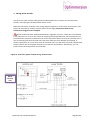
Wired versions: Optimmersion Simple & Optimmersion Wired. The power throttle should be installed
adjacent to the property’s main consumer unit, incoming electrical supply, and the point at which the
PV plant’s dedicated supply circuit connects to the consumer unit.
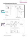
Wireless versions :Optimmersion wireless & Optismart Hot Water. The power throttle can be
installed anywhere along the immersion heater spur.
Please note that there are separate wiring diagrams and instructions for wired and wireless versions.
Warning: the power throttle may run hot at times! Mount the unit on a non-flammable vertical
surface and make sure that air is free to run through the vents. If in doubt, we recommend spacing
the power throttle from the wall surface by 10 mm.
UK only Warning: inspect the existing immersion heater integral thermostat to ensure that it
complies with safety requirements and regulations to provide thermal overload protection where the
hot-water system includes a plastic header tank. Replace the thermostat if necessary.
2. Mount controller unit
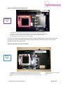
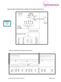
Remove the lid by gently pressing in the centre of the upper side of the base. The cover will release
from the top, hinging at the bottom. Refit the lid by aligning the two locators at the bottom, gently
pushing home at the top.
Mount the controller unit carefully on a flat surface so as not to distort the enclosure. Failure to do
this may result in damage to the unit and poor fitting of the cover.
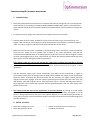
The cable entry slot is designed to allow the power and phono cables to be threaded through from
the rear or from the bottom. The plugs may be inserted into their respective sockets prior to final
fixing. We recommend that you first prepare and loosely fix the unit to the wall, and then, before
tightening the fixings, thread the plugs through the cable entry slot and insert them into their
respective sockets, starting at the top and working down.
Optimmersion Installation Manual
Page 3 of 12