1
3. Wiring power throttle
Use the 5-core cable and PVC cable glands provided between the consumer unit and the power
throttle, intercepting the dedicated water heater circuit.
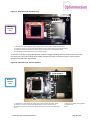
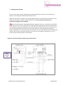
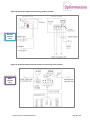
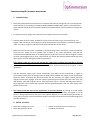
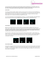
Make the connections as shown in the wiring diagrams, Figures 2a, 3a and 4 for wired versions, and
Figures 2b, 3b and 4 for wireless versions below. At this stage, please leave both current
transformers plugged in but unclipped.
British standard BS 7671: 2008 (amended 2011), regulation 537.3.2.1, allows the circuit-breaker
in the consumer unit to act as the means for switching off the Optimmersion and associated circuits
for maintenance purposes provided that you mount the power throttle near by the consumer unit. If
you are mounting the power throttle some way away from the circuit-breaker (for example, in
another cupboard or in a room away from the consumer unit), you will need to provide a double-pole
isolation switch next to the power throttle as an means for local isolation. Alternatively, you can
install a means of locking off the circuit-breaker.
Figure 2a: Controller/ power throttle wiring, wired versions
Wired
versions
only
Optimmersion Installation Manual
Page 5 of 12