1
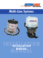
Multi-Line Systems
INSTALLATION
INSTALLATION
MANUAL
MANUAL
Index
This Publication covers the fitting and
connecting of Interlube’s range of Multi-Line
Automatic Chassis Lubrication Systems
AC SERIES
INTRODUCTION
FOR MORE INFORMATION ON PUMP OPERATION AND
SPARES PLEASE REFER TO MULTI-LINE OPERATION
AND MAINTENANCE GUIDE.
DO’S AND DON’TS Health & Safety at Work Act 1974
DO’S AND DON’TS
Do’s
1. General System Description
Do read all instructions before commencing installation.
2. Planning The System
Do observe safety regulations regarding operating the
vehicle in confined spaces.
3. Preparing The Pump
Do take precautions to keep all components in the
system clean.
4. Siting/Mounting The Pump
Do use existing holes in chassis for mounting where
possible.
5. Making the Looms
Don’ts
6. Fitting The Looms
Don’t drill any holes in chassis flanges.
7. Connecting The Looms
Don’t drill holes through any part of the vehicle until you
have checked the area is free of electric cables and pipe
work.
8. Eletrical Connections
Don’t drill a series of holes that may cause a
weakening of the chassis.
9. Testing The System
Don’t attach Interlube pipe work to the existing pipes
that are subject to heat, e.g. the outlet pipe from the
vehicle air compressor etc.
10.Timer Adjustment
11.Accessories
Don’t work underneath raised body without full body
props in place.
SAFETY PRECAUTIONS
(Health and Safety at work Act 1974)
UK Headquarters:
Interlube Systems Ltd
St Modwen Road, Parkway Industrial Estate,
Plymouth, Devon, England PL6 8LH
Tel: +44 (0)1752 676000
Fax: +44 (0)1752 676001
e-mail: [email protected]
Web Site: www.interlubesystems.com
Never direct High Pressure Air, Grease or Oil Delivery
Nozzles at any part of the body. Always switch off and
remove the fuse from the electrical supplies, uncouple
pressure supplies before commencing any maintenance
work. Make sure that any guards or covers removed for
maintenance work are replaced before operating the
equipment.
USA Headquarters:
Interlube Systems Inc
4696 Wadsworth Road,
Dayton, Ohio, 45414, USA
Tel: + 1 937 276 4507
Fax: + 1 937 276 4518
e-mail: [email protected]
1
1. GENERAL SYSTEM DESCRIPTION
3. PREPARING THE PUMP
The Interlube AC range has been designed to provide
reliable and virtually maintenance free service in the most
demanding applications. The system comprises an
electrically operated 12/24 V pump with integral controller,
and a loom of tubing which connects each chassis bearing
directly to its own respective pumping unit. Each bearing is
fed independently, meaning that points can be individually
calibrated, and also damage to one line does not affect the
rest of the system. The pumps come in two variations; the
AC1 and AC2 (fig 2) which have 1 & 2 litre top fill
reservoirs and have the motor and controller housed in the
lid, and the AC3 (fig 1) which has a 3 litre reservoir and has
the motor and controller housed in the pump base. The
motor drives the impellor, which draws grease into the
pumping chamber and also gives a visual indication of cam
rotation. It also drives the cam, which operates the
individual pumping units, and feeds grease into the tubing.
The pumps can operate with a wide range of lubricants
from SAE 80 oil up to and including NLGI grade 2 grease.
Fit the pumping units into the carcass ring of the pump,
taking care not to over tighten. Where spare positions
occur, use blank plugs. It is recommended that where
possible pumping units are spaced symmetrically around
the pump and not grouped together in one area.
PUMPING UNITS
Each chassis bearing requires a measured volume of
lubricant, determined by size and function. To meet this
requirement INTERLUBE provides a range of six
pumping units, with the outputs shown below, colour
coded for easy identification during instalation, and with
push-in type tubing cartridge.
Red
0.010 cc ...............................78033
Green
0.015 cc ...............................78034
Yellow
0.025 cc ...............................78035
Blue
0.040 cc ...............................78036
Grey
0.060 cc ...............................78037
Black
0.100 cc ...............................78038
Blanking Plug .............................................34237-402
2. PLANNING THE SYSTEM
1. Tilt cab (where applicable).
2. Flush out all bearings to be connected to the system
and clean all bearing surfaces.
3. Remove grease nipples and insert connectors to
establish number of bearings to be lubricated.
4. Prepare specification sheet by listing bearings to be
connected and referring to the calibration chart to determine
pumping unit output recommendation.
Manual
Over-Ride
Button
FIG 2
•
FIG 1
•
•
Quick-Fill
Connector
•
•
Manual
Over-ride
Button
Filling
Point for
Oil/Soft
Grease
•
Timing
Adjustment
2
Filling
Adaptor for
Heavy Grease
4. SITING/MOUNTING THE PUMP
FIG 3
Select a suitable mounting point for the pump on main
chassis in a position where it is protected from debris
thrown up by the wheels. Ensure adequate clearance for
reservoir top-up to be achieved. Do not mount the pump
onto ancillary equipment (i.e. battery covers etc).
Using the adhesive template supplied, position and drill
the bracket mounting holes as shown in figs 5 & 6 (see
Do’s and Don’ts page 1). Using the spring washers and
screw/nuts secure the pump in position.
AC3 (3 litre Reservoir)
Maximum 60 Lubrication Points.
For more than 60 points please contact Interlube.
Operates for up to 2000 hours on each reservoir filling.
FIG 4
AC2 (2 litre Reservoir)
Maximum 36 Lubrication Points.
Operates for up to 1500 hours on each reservoir filling.
FIG 5
FIG 6
AC1 & AC2
AC3
CALIBRATION CHART
1.
2.
3.
4.
5.
6.
7.
8.
9.
10.
11.
Typical Multi-line Chassis Layout
Pumping Unit
Power Steering Cylinder Front
Power Steering Cylinder Intermediate
Power Steering Cylinder Rear
Track Rod End
Shackle Pins Front
Clutch operating Shaft (Split Feed* - see note)
Spring Pins
Shackle Pins Rear
Brake Cam Shaft Front
King Pins
Brake Cam Shaft Rear
*Split Feeds are only permitted on oil lubrication systems.
Grease Systems
TypicaI Bearing Chart
0.025
0.025
0.025
0.040
0.040
0.015
0.025
0.040
0.015
0.040
0.015
MULTI-LINE
EXPLODED VIEW
TYPICAL
MULTI-LINE
CHASSIS
LAYOUT
Other Bearings usually connected to the lubrication system:
Balance Beam Bearings (2 feeds)
Drag Link Ball Joint
Gear Lever Linkage
Accelerator Cross Shaft
Pedal Linkages
Brake Slack Adjusters
Tipping Body Hinges
Fifth Wheel Coupling Pivot Point
Fifth Wheel Coupling Jaws
2 x 0.040
0.040
0.015
0.015
0.015
0.025
0.025
0.025
0.025
Y
Z
3
Pump
Ignition
Controlled
Electrical Supply
5. MAKING THE LOOMS
7. CONNECTING THE LOOMS
The loom should be formed using Interlube 4mm
semi-rigid nylon tubing. It is recommended that grease
filled tube is used so that the system does not have to
be primed prior to operation. From the pump position
ascertain the most convenient favourable route for the
looms. The number of looms required will depend on
pump location and quantity and positioning of grease
points. Using looming stands if available, form individual
tubes into a loom allowing sufficient length for
connection to pump and bearings and allowing for
chassis movements (e.g. springs, steering, lifts etc). In
conjunction with the installation record sheet fit number
identification sleeves to tubing at pump and bearing
ends. The loom should be protected along its length with
the conduit/spiral binding/sleeving, and/or tape (for part
numbers see section 11 Accessories) The loom can
consist of tubes of varying lengths which can leave the
loom at the required point (fig 7).
Cut each tube to length ensuring a clean square cut is
achieved, and connect to bearing using push fit
connectors. ENSURE TUBING IS PUSHED FIRMLY INTO
CONNECTOR. TEST ASSEMBLY BY PULLING FIRMLY ON
THE TUBE. Using System Specification Sheet connect
the loom to corresponding numbered pumping units.
When running the tubing into the pumping units, to give
the loom strength and rigidity, the tubes should be
clipped together to form an arrangement as shown in fig
(8) below. The starting point for the loom can be as
required. On the underside of the AC2 a mark indicates a
suggested starting point. Starting with the bottom row of
outlets, and pumping unit 1, the loom should then run
right around the pump, then on to connect with the next
row of pumping units so that the loom takes the form of
a spiral, and so on until all pumping units are connected.
Alternatively the pump units in all rows can be connected
by working around the pump ring, but the loom should
still be formed as per fig 8. Alternatively the loom can be
run in the opposite direction. Approximate distance of the
loom from pump should be approx 60mm. Tubes should
be clipped together every 6 pump units. The loom/looms
can then be routed on to the chassis as required.
6. FITTING THE LOOMS
Working from the furthest point from the pump, feed the
loom through the chassis following existing vehicle
services where possible (see do’s and don’ts page 1).
Ensure tubes are positioned to fit bearing connectors.
Where bearing is on a moving part, ensure tube length is
sufficient to allow for full movement. To avoid rubbing or
friction with chassis, grommets or protective sleeving
should be used.
FIG 8
60
Loom Direction
FIG 7
Protective sleeving
Half Lapped Tape
Loom stand
Sufficient length of tube
to reach bearing points
Loom stand
Pinch a tab of tape across
the end of the tube to
secure the I.D. No.
2
4
3
Typical Loom Stand
4
5
FIG 9
8. ELECTRICAL CONNECTIONS
Connect the twin core cable via an in line fuse (2Amin/5A
max) to an ignition controlled circuit. See figures 9 & 10.
INSTALLATION DIAGRAM AC1 & AC2
9. TESTING THE SYSTEM
With the ignition ON, check that the indicator light is
illuminated (see figures 11 & 12). Operate the manual
override button, and check for paddle rotation. The
indictor light should flash slowly. NB. Should the motor
fail, it will be indicated by a fast flash.
10. TIMER ADJUSTMENT
AC1 / AC2
The pump cycle time can be changed from the factory
set option if required. There are four settings as listed
below and show the cycle time including 2.5min run
time and delay period. The rotary timer is on the PCB
which is inside the motor housing. This is accessed by
removing the lid, and opening the motor housing.
FIG 10
INSTALLATION DIAGRAM AC3
The switch positions are:0- Continuous (2.5 min cycle time)
1- 9 minutes cycle time
2- 12 minutes cycle time
3- 15 minutes cycle time
AC3
The pump is available with 10 settings with the delay
timing control via a rotary switch located behind a screw
cap at the front of the motor housing. The motor runs
for 1 minute and 8 seconds.
Switch positions:0 – continuous double speed (1.8 RPM)
1 – continuous at normal speed (0.9RPM) normal
trailer applications.
2 – 3 minute delay (4 minute total cycle time)
3 – 7 minute delay (8 minute total cycle time)
4 – 11 minute delay (12 minute total cycle time)
5 – 15 minute delay (16 minute total cycle time)
6 – 19 minute delay (20 minute total cycle time)
7 – 24 minute delay (25 minute total cycle time)
8 – 30 minute delay (31 minute total cycle time)
9 – 36 minute delay (37 minute total cycle time)
FIG 11
FIG 11
FIG 12
Manual
Override
button
•
Indication
Light
•
•
•
Indication
Light
FIG 12
5
Manual
Override
button
LOOMING ACCESSORIES
11. ACCESSORIES
Plastic tape 1” Black . . . . . . . . . . . . . . . . . 1755-830
Spiral Binding (1-2 lines). . . . . . . . . . . . . . 1837-001
Spiral Binding 8mm I/D (3-4 lines) . . . . . . 1837-002
Spiral Binding 10mm I/D (5-7 lines) . . . . . 1837-003
Spiral Binding 14mm I/D (8-12 lines) . . . . 1837-004
Conduit 7mm diameter. . . . . . . . . . . . . . . . 27315-707
Conduit 10mm diameter. . . . . . . . . . . . . . . 27315-710
Conduit 12mm diameter. . . . . . . . . . . . . . . 27315-712
Conduit 17mm diameter. . . . . . . . . . . . . . . 27315-717
Split Conduit 7mm diameter . . . . . . . . . . . . 27315-907
Split Conduit 10mm diameter . . . . . . . . . . . 27315-910
Split Conduit 12mm diameter . . . . . . . . . . . 27315-912
Split Conduit 17mm diameter . . . . . . . . . . . 27315-917
ELBOW CONNECTORS
GREASE
Premium Grade NGLI 000 / FG3,0
25717-284
Bottles
25717-284 / 12.5K
25717-284 / 25K
25717-284 / 50K
25717-284 / 180K
STRAIGHT CONNECTORS
12 x 1 Litre
12.5 KG Pail
25 KG Pail
50 KG Pail
180 KG Pail
NLGI Grade 2
25717-270 / 12.5K
25717-270 / 25K
12.5 KG Pail
25 KG Pail
GREASE SPECIFICATIONS
NGLI 000 / FG3,0
Colour .....................................................Amber
Texture.....................................................Fluid, Tacky
NLGI........................................................000
Soap Type ...............................................Calcium
Penetration @ 25°C.................................445-475
Base Viscosity @ 40°C ...........................35 to 45 CST
Drop Point ...............................................N/A
ACCESSORIES
152823/25 .........4mm OD soft grease filled tube x 25M
152823/50 .........4mm OD soft grease filled tube x 50M
152821/25 .........4mm OD Heavy grease filled tube x 25M
27233-507 .........Cable ties
OA50397/1
OA50397/2
OA50397/3
OA50397/4
OA50397/5
2 off
2 off
2 off
2 off
2 off
NLGI Grade 2
Colour .....................................................Pale Amber
Texture.....................................................Slightly Fibrous
NLGI........................................................2
Soap Type ...............................................Lithium
Penetration @ 25°C.................................265-295
Base Viscosity @ 40°C ...........................125cSt
Drop Point ...............................................185°C
Numbered sleeves 1 – 12
Numbered sleeves 1 – 24
Numbered sleeves 1 – 36
Numbered sleeves 1 – 48
Numbered sleeves 1 – 60
6
MULTI-LINE INSTALLATION RECORD
Vehicle Type ................................................................
Voltage .......................................................................
Customer ....................................................................
Timer Settings ............................................................
....................................................................................
Pump No .....................................................................
SYSTEM TYPE
AC1
AC2
AC3
SYSTEM SPEC’ SHEET
Unit
No.
1
2
3
4
5
6
7
8
9
10
11
12
13
14
15
16
17
18
19
20
21
22
23
24
25
26
27
28
29
30
Bearing
Lubricated
Col.
Code
Cal
cc.
Unit
No.
Bearing
Lubricated
Col.
Code
Cal
cc.
31
32
33
34
35
36
37
38
39
40
41
42
43
44
45
46
47
48
49
50
51
52
53
54
55
56
57
58
59
60
Installed by .................................................................................................... Date ...........................................................