1
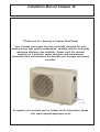
Installation Manual Compac 12
OWNER AND INSTALLATION MANUAL
FOR
COMPAC 12
SWIMMING POOL HEAT PUMP
(SD636651 Iss.3 09/03/11)
Health and Safety Warning:
As the heat pump includes electrical and rotational components it is required that only trained
and competent persons should remove panels giving internal access to the unit.
Page 1
Installation Manual Compac 12
TThank you for choosing a Compac Heat Pump!
Your Compac heat pump has been specially designed for pool
heating using high quality components, carefully chosen to provide
maximum efficiency and reliability. Please read this manual
carefully as it provides useful operation and maintenance
information that will maximise the benefits your Compac heat pump
can offer.
To register your product and for further useful information please
visit www.compacheatpumps.co.uk
Page 2
Installation Manual Compac 12
Contents
1.0 Introduction ................................................................................................................ 4
1.1 Function ............................................................................................................ 5
2.1 Siting ................................................................................................................ 6
2.0 Installation ................................................................................................................. 6
2.2 Air flow .............................................................................................................. 7
3.0 Plumbing ................................................................................................................. 8
3.1 Recommended Plumbing Schematic .............................................................. 10
3.2 Determining Water Flow.................................................................................. 11
4.0 Electrolytic Corrosion in Swimming Pools................................................................ 12
4.1 Electrical (Machine Wiring and Supply). ......................................................... 13
4.2 Location of Mains Input ................................................................................... 14
4.3 Pool Pump Synchronisation ..........................................................................
15
5.0 Controls and indication lamps ................................................................................. 16
6.0 Circuit Diagram ....................................................................................................... 17
7.0 Regular planned maintenance ................................................................................. 18
8.0 Heat Pump Malfunction ............................................................................................ 19
8.1 User Check List .............................................................................................. 19
9.0 Datasheet ............................................................................................................... 20
10.0 Installation Drawings .............................................................................................. 21
11.0 Winterisation Procedure ........................................................................................ 22
11.1 Start up Procedure After Winterisation ........................................................... 23
12.0 Warranty Conditions .............................................................................................. 24
12.1 Service Contact ............................................................................................ 24
Page 3
Installation Manual Compac 12
1.0 Introduction
The Compac 12 air/water heat pump is designed for swimming pool heating.
The heat pump is designed to heat pool water and spas within the range of
15°C to 35°C, and is suitable for outdoor pools operating in ambient
temperatures above 5ºC.
The water heat exchanger is a full flow type, manufactured from titanium
tube, which is a highly corrosion resistant material. The heat pump is suitable
for use in fresh water and salt water pools. The heat pump is fitted with a
rotary compressor known for quiet running.
A 3 minute cycle time delay is incorporated for compressor protection. With
these features the heat pump is designed to have a long, trouble free life.
All units have integral safety devices to protect the heat pump from internal
and external faults. Indicator lamps indicate operating mode. An adjustable
digital thermostat controls the water temperature.
Page 4
Installation Manual Compac 12
The swimming pool heat pump provides thermodynamic heating by means
of a vapour compression cycle, (similar to that employed in a conventional
refrigerator), in addition to acting as an active solar collector.
1.1 Function
1. THE EVAPORATOR collects the heat from the outside
ambient air, pre-heated by the sun. In the swimming pool
heat pumps, high volumes of outside air are drawn into the
unit by the fan and expelled through the evaporator fins.
The evaporator has liquid refrigerant passing through it,
which is at a considerably lower temperature than the
ambient air, therefore the air gives up its heat to the
refrigerant which then vaporises.This preheated vapour
now travels to -
2. THE COMPRESSOR
where it is compressed
and upgraded to a much
higher temperature. The
hot vapour now enters -
THE HEAT PUMP CYCLE
2
COOL GAS
COMPRESSOR
HOT GAS
HEATED
WATER TO
POOL
AMBIENT
AIR
3
1
HEAT
EXCHANGER
EVAPORATOR
WATER
FROM POOL
CONDENSED
REFRIGERANT
COOL LIQUID
REFRIGERANT
LOW PRESSURE SIDE
4. THE EXPANSION DEVICE
and from there, now at normal
pressure, it is returned to the
evaporator and the cycle starts
again.
EXPANSION
VALVE
4
HIGH PRESSURE SIDE
3. THE CONDENSER where it is surrounded by the pool
water. The heat is given up to the cooler pool water and the
now cooler refrigerant returns to its former liquid state but
still under high pressure from the compressor.
This pressure is released by passing the liquid through -
Coefficient of Performance
The efficiency of a Heat Pump is usually called its ‘Coefficient of Performance’ - (C.O.P.)
which is simply a ratio of heat output to energy input, both being expressed in kW. Thus a
Heat Pump absorbing 1 kW of electricity, collecting 4 kW of energy from the air, and
delivering 5 kW of heat to the pool water is said to have a C.O.P. of 5:1.
This ratio will vary according to the temperature of the water and the ambient air.
Page 5
Installation Manual Compac 12
2.0 Installation
a) Ensure that the heat pump on site is as ordered, i.e. model, electrical
supply and factory fitted options.
b) Inspect the unit for damage, in particular inspect the evaporator (finned
side) to ensure that it is undamaged. (Minor indentations in the fins do not
affect performance). If severely damaged, endorse the delivery note in
presence of the driver and send a recorded delivery letter to the transport
company giving details.
c) Protect the unit if installation is delayed.
2.1 Siting
a) Provide a firm level base capable of supporting the weight of the unit;
spread the load if mounted on timber floor.
b) Ensure that water cannot collect under unit, it is recommended that units
are installed on plinths 100mm above finished floor level. This also aids
condensate drainage.
c) Please allow adequate clearance to service panels on the unit;
recommended 500mm minimum.
d) The heat pumps are by design as quiet as is practical, however due
consideration should be given to siting the heat pump in order to minimise
theeffect of noise coming from the machine, for example by positioning the
machine so that the inlet/outlets are parallel to occupied premises.
e) Ensure loose debris such as leaves, grass cuttings, etc will not block air
inlet grilles.
f ) Consider protection from extreme weather conditions if installed externally,
i.e. lean-to-cover or building.
g) Use the antivibration feet provided, not only does this help to reduce noise
but it also will help prevent corrosion to the base of the heat pump. Use of
stainless steel fixings is recommended.
Page 6
Installation Manual Compac 12
2.2 Air flow
Due consideration must be given to air flow i.e. do not obstruct either the
inlet or outlet and ensure that the discharge to air cannot recirculate to
inlet. (See below).
POSSIBLE POSITIONS OF A HEAT PUMP
Suitable opening
Suitable opening
HEAT PUMP
HEAT PUMP
> 50 cm
HEAT PUMP
PLANT ROOM
WALL
HEAT PUMP
WALL
HEAT PUMP
SWIMMING POOL/SPA
TABLE 1
Minimum Free Area m²
Inlet
Discharge
0.21
0.145
Required Free Areas to provide air flow to
and from heat pumps when installed in an
enclosed area or where required to pass air
through a wall etc.
Free area is the available area through which
air can pass through a grille or louvres.
IMPORTANT
If multiple units are installed in an enclosed area then the inlet free areas
required for each unit can be added together to form one inlet aperture.
BUT the discharge from each unit must be kept separate and must not be
incorporated into one common duct system.
Page 7
Installation Manual Compac 12
3.0 Plumbing
a) The heat pump has water inlet/outlet connections as follows:
The heat pump can be connected to either 1 1/2” or 50mm plastic pipe.
b) The Heat Pump must be connected after the filter in the return pipe to the
pool. If an existing heater is being retained, then the Heat Pump should be
connected between the filter and the other heater. (See section 3.1).
c) Suitable breakable couplings should be installed local to the heat pump.
d) If the heat pump is installed at a lower level than the pool then isolation
valves should be fitted.
e) A drain valve or plug should be fitted to the lower pipe to facilitate draining
water in the winter period.
f) Connections on all models via by either 1 1/2” or 50mm plastic pipe. The
pipes need to be glued into the water in/out connections with a suitable
adhesive.
g) The condensate drain in the base of the unit collects condensation from
the evaporator fins. This should run away to waste using the flexible
drainage tube provided. It is therefore necessary to ensure that the Heat
Pump is placed on a level plinth so that the condensate water can run
away and not overflow the edges of the drip-tray inside the unit. The
position for fitting the condensate adaptor is in the base of the unit. It will
be easier to fit this and the hose BEFORE the Compac heat pump is
connected to the water supply.
WATER
OUT
WATER
IN
HOSE
CONDENSATE ADAPTOR
FIT IN HOLE IN BASE OF UNIT.
APPROXIMATE POSITION
SHOWN
NOTE: FITTINGS SHOWN AT
LARGER SCALE FOR CLARITY
Page 8
Installation Manual Compac 12
h) When the pipework installation is complete the pool circulation pump
should be switched on and the system tested for leaks. Also check the filter
gauge to see that there is not an excessive increase in back pressure. If
everything is then working normally the water circulating system is ready for
use.
i) The water circuit to and from the unit is to be capable of maintaining within
specified limits, the rate of flow required by the heat pump. (See section 10).
j) All pipework must be adequately supported with allowance for expansion or
contraction especially with plastic pipework.
k) It is recommended that when installing water systems,that the last
connections to be made in the system should be breakable connections to
avoid any stresses on the unit connections.
IMPORTANT
1. All Pool Purifying Devices and Chemical Injection Systems should be
fitted down stream of the heat pump (see section 3.1) unless installation
is as per filter dosing. This includes the practice of dosing chemicals
direct into skimmer basket, which results in concentrated corrosive
liquids passing over vulnerable metal components.
Acidity pH
Total Alkalinity, as CaCO3
Total Hardness, as CaCO3
pH
ppm
ppm
7.2 - 7.8
80 - 120
150 - 250
Total Dissolved Solids
Maximum Salt Content
ppm
ppm
1000 Max
35000 Max
Free Chlorine Range
ppm
1 - 2 Domestic
Free Chlorine Range
Superchlorination
ppm
max
3 - 6 Commercial
30ppm for 24 hrs
Bromine
Baquacil
ppm
ppm
2-5
25 - 50
Ozone
ppm
0.9 Max
Maximum Copper Content
Aquamatic Ionic Purifier
ppm
ppm
1
2 Max
2. Water quality must be maintained as follows:
3. Maximum pressure of water in the heat pump circuit should not exceed
3kg/cm (50 psi)
Page 9
Page 10
TO WASTE FOR
WINTERISING
DRAIN DOWN
KEY
ISOLATION VALVE
ANTI RETURN LOOP
TO BE INCORPORATED,
MINIMUM HEIGHT
100mm ABOVE HEAT PUMP
OUTLET PORT
(IF SANITISER FITTED)
100mm
AUX HEATER
IF FITTED
NON RETURN VALVE
SPARE PORT FOR
WINTERISING
FLUSHING
CONNECTION
TO WASTE
FILTER
CONDENSATE WATER TO
WASTE
DEVICE, IF FITTED
SANITISER OR
CHEMICAL DOSING
BREAKABLE COUPLING
BYPASS VALVE
NORMALLY SHUT
NON
RETURN
VALVE
THREE WAY VALVE
PUMP
POOL
Installation Manual Compac 12
3.1 Recommended Plumbing Schematic
Installation Manual Compac 12
3.2 Determining Water
Flow
The heat pump is fitted with a water flow switch which inhibits the
operation of the heat pump when the water flow is below
5000L/hour (83L/min). Error E3 on the digital thermostat will be
shown until the correct flow rate is achieved. Once this error has
disappeared from the thermostat the flow rate is adequate.
POOL WATER OUT
ECO
POOL WATER IN
CONDENSATE DRAIN IN BASE
HEAP PUMP WATER OUT CONNECTIONS
Flow rate: 5000 to 8000L/hour
Page 11
Installation Manual Compac 12
4.0 Electrolytic
Corrosion in Swimming
Pools
Electrolytic corrosion will occur when dissimilar metals that are in
contact with each other create a potential difference between
themselves. Sometimes separated by a conductive substance
known as an electrolyte, the dissimilar metals will create a small
voltage (potential difference) that allows the ions of one material to
pass to the other.
Just like a battery, ions will pass from the most positive material to
the more negative material.
Anything more than 0.3 volts can cause the most positive material to
degrade.
A swimming pool with its associated equipment can create this effect.
The pool water being an ideal electrolyte and components of the
filtration circuit, heating system, steps, lights, etc. providing the
dissimilar metals needed to complete the circuit.
Whilst these small voltages are rarely a safety threat, they can create
premature failure through corrosion. Not dissimilar to corrosion
through oxidation, electrolytic corrosion can cause complete failure
of a metallic material in a very short period of time.
In order to prevent this type of corrosion all metallic components in
contact with swimming pool water should be bonded together using
10mm² bonding cable. This includes non-electrical items such as
metal filters, pump strainer boxes, heat exchangers, steps and handrails. It is highly recommended that bonding be retrofitted to existing
pools, which may not be protected by this system.
Page 12
Installation Manual Compac 12
4.1 Electrical
(Machine Wiring
and Supply).
See section 4.2
All electrical work to be carried out in accordance with l.E.E. standards,
latest issue, or local codes of practice as applicable.
The machine should be installed in line with EMC2004/108/EC.
Protected supply to incorporate fuses or motor type circuit breakers (Type
C) to specified rating, (see Data Sheet). H.R.C. fuses are recommended. An
isolator which disconnects all poles must be fitted within 2m and in sight of
machine.†
All units must be correctly earthed-grounded. An earth leakage trip of the
Current operating type (30mA) is recommended to be fitted to all pool
electrics.
INCONSISTENT ELECTRICAL SUPPLY
The following limits of operation must not be exceeded if machines are to be
guaranteed either in performance or warranty terms:
Minimum
Maximum
Voltage single phase
207V
253V
Frequency - Hz
47,5
52,5
This voltage must be made available at the heat pump while running.
† Note the Isolator must have a minimum of 3mm air gap when turned off.
IMPORTANT
The user should be made aware that THE WHOLE installation should be
isolated when working on ANY PART OF THE INSTALLATION
Page 13
Installation Manual Compac 12
4.2 Location of Mains
Input
ECO
The Compac heat pump is supplied with 5m of cable
which needs to be hard wired to an appropriate MCB (see
data sheet).
Page 14
Installation Manual Compac 12
4.3 Pool Pump
Synchronisation
For installations where the filter pump, which also provides water to your
heat pump, is controlled by a time clock (supplied by the installer) your
heat pump can over-ride “pump off” periods set on the time clock so that
the filter pump will run if your swimming pool requires heating. By doing so
your filter pump will only run when:
a) A block period of pump “running” has been set on the time clock for
filtration purposes.
b) The pool requires heating.
This feature operates by overriding the filter pump time clock for three
minutes each hour so that water is pumped through the heat pump.
If during this sampling period the heat pump detects a need for water
heating it will continue to over-ride the time clock until the swimming pool
temperature is satisfied. If water heating is not required, the filter pump will
turn off after the three minute sampling period and not restart until the next
hourly sampling period or time clock pre set run time. This feature will
reduce the filter pump run time and consequently save energy as well as
unnecessary filter pump wear and tear.
LP2 LP1 FS FS
LINE VOLTAGE
OUT TO PUMP
CONTACTOR
L
N
L
N
TERMINALS IN
HEAT PUMP
FLOW
SWITCH
TIME
CLOCK
L N
POWER SUPPLY
~230N 50Hz
L
PUMP
CONTACTOR
AC
N
POOL PUMP
Page 15
Installation Manual Compac 12
5.0 Controls and
indication lamps
CONSOLE
DEFROST
LAMP
ECONOMY
MODE LAMP
FAULT LAMP
ECO
ECONOMY MODE
INCREASE TEMPERATURE
ON/OFF SWITCH
DECREASE TEMPERATURE
NOT USED
Using the “ECO” button makes the heat pump more economic to run.
When this lamp is illuminated, ECO mode is on.
When the ECO switch is pressed the heat pump will stop
working when the ambient temperature is below 5ºC and will
restart automatically once the ambient temperature is above
10ºC.
Page 16
Installation Manual Compac 12
6.0 Circuit Diagram
COM PAC 12 SINGLE PHASE 230V~1N 50Hz
Page 17
Installation Manual Compac 12
7.0 Regular planned
maintenance
Operations to be carried out during a regular planned maintenance visit are
as follows:
1.
Check and clean the evaporator. (This action may be required
more frequently than regular servicing).
2.
Check operation of fan and compressor.
3.
Check capacitor tolerances - where fitted.
4.
Check condition of the water heat exchanger.
5.
Check refrigeration system parameters.
6.
Check operation of control valves.
7.
Check for water leaks.
8.
Check driptray and internal drain lines for blockages and
clear.
9.
Check operation of controls and calibrate if necessary.
10.
Check operation of interlocks in use.
11.
Final check of overall operation of unit
12.
Indicate on Service report any faults found or causes for
concern.
13.
Recommended servicing frequencies:
- Light to medium use:
one visit per year
- Heavy use:
two visits per year
Page 18
Installation Manual Compac 12
8.0 Heat Pump
Malfunction
WARNING: Isolate heat pump electrically before entering heat pump or
removing panels.
The user check list should be carried out before initiating a service call.
Do not attempt to interfere with any internal control settings as these have
been factory calibrated and sealed.
Any sign of abnormal operation such as water dripping should be reported
immediately to an installer. If in doubt or if advice is required contact the
Service Department.
Telephone +44 (0)1621 857171
8.1 User Check List
The digital thermostat will display one of the following error codes in the
event of a heat pump malfunction.
E1 The water temperature probe is not working
correctly, contact dealer.
E2 The condenser temperature sensor is not
working correctly, contact dealer.
E3 Water flow through heat pump is inadequate, check pool water ciruit for blockages.
E4 Indicates high or low pressure trip,
contact dealer.
E5 There is a refrigerant leakage,
contact dealer.
Page 19
Installation Manual Compac 12
9.0 Datasheet
MODEL
Units
COMPAC12
HEAT TO POOL WATER
AMBIENT 20°C, WATER 27°C
kWh
11.6
ELECTRICITY
ELECTRICAL SUPPLY 1 PHASE
230V/~1N/ 50Hz
TOTAL POWER CONSUMED
AMBIENT 20°C, WATER 27°C
kWh
2.56
A
A
11.8
20.0
WATER FLOWS ETC
POOL WATER FLOW RATE:-
L/min
133
MAX WORKING PRESSURE POOL WATER:POOL WATER CONNECTIONS:POOL WATER FLOW RATE:-
bar
inches
L/h
4
1 1/2" FEMALE or 50mm
5000-8000
CONDENSATE DRAIN CONNECTIONS:-
mm
15
MAIN FAN
AIR FLOW (Anemometer @ air on grille. Dry evaporator):-
m³/h
1600
kg
1.4
PHYSICAL DIMENSIONS
WIDTH (Unpacked):DEPTH (Unpacked):-
mm
mm
848
300
HEIGHT (Unpacked):WEIGHT (Unpacked):-
mm
kg
630
63
WIDTH (Packed):DEPTH (Packed):HEIGHT (Packed):WEIGHT (Packed):-
mm
mm
mm
kg
980
395
700
66
MIN SUPPLY CAPACITY (Max F.L.A.) 1 ph N:RECOMMENDED SUPPLY FUSE 1 ph N:-
GENERAL DATA
HERMETIC SYSTEM
GAS CHARGE
R410a
SOUND LEVEL
dBA
FOR ACCURATE APPLICATION SIZING CONSULT SUPPLIER
52
NOTES
1) Weight and dimensions nett.
2) Performance design limitations: Ambient = 5º C min 40ºC max, Water = 15º C min, 35ºC max.
3) Pool w ater to have correct balance, pH 7.2-7.8, Free Chlorine 1.0 - 2.0ppm domestic, 3.0 - 6.0 commercial.
4) Allow 500mm clearance to service panels.
5) Compac heat pumps reserve the right to change or modify models w ithout prior notice.
6) R410a Global w arming potential (GWP) 1997.
1mm WG = 9.8 Pa
1mhd = 1.4 psi
1l/min = 0.22gall/min
Page 20
Page 21
500
AIR OUT
DIA 430
Compac12
drain valve and
drain tube
COMPAC 12
WATER IN/OUT 1½" FEMALE or 50mm CONNECTORS
CONDENSATE 15mm CONNECTOR
174
285
848
30
ECO
80
365
90
307
630
190
110
WATER
IN
WATER
OUT
27
632.50
AIR IN
25
510
55
35
42
AIR IN
206
480
70
10.0 Installation Drawings
Installation Manual Compac 12
420
Installation Manual Compac 12
11.0 Winterisation
Procedure
WARNING. Isolate machine before removing covers!
The heat pump embodies electrical and rotational
equipment, it is recommended for your own safety that a
competent person carries out the following procedure.
ALL MODELS
Objective
To provide frost protection
To eliminate corrosion problems
To inhibit electrical components
1. Switch off the electric supply to the heat pump.
2. Remove external fuses and keep in safe place away from heat pump to
prevent accidental operation of heat pump.
3. Ensure that the water circulation pump is switched off.
4. Drain water from heat pump by:
a. drain valve if fitted
b. disconnecting pipework to and from heat pump
5. Flush through water circuit in heat pump by using CLEAN TAP WATER
(NOT POOL WATER) via hose into outlet connection - run the hose for 10
minutes minimum; use spray nozzle if available.
6. Allow to drain - when drained, fit plastic bags secured by elastic bands
over water connections.
7. Uncover electrical enclosure (see section 4.2) and liberally spray interior
of unit, with moisture-repellant aerosol WD40 or similar; reseal enclosure.
8. If the heat pump is located outside, protect from weather by covering with
VENTILATED cover. Do not use plastic sheet as condensation could occur
within the unit.
IMPORTANT
If this procedure is not adopted and frost or corrosion damage
results then the warranty will become invalid.
Page 22
Installation Manual Compac 12
11.1 Start up Procedure
After Winterisation
1.
Replace covers (if not fitted).
2.
Remove front grille, using a soft brush clean the finned surfaces of
evaporator. Replace panel.
3.
Remove plastic covers on water connections and reconnect water
piping or close drain valve.
4.
Start up water circulating pump and leave running for at least 1/4
hour to establish flow and enable an air in piping to escape.
5.
Replace fuses to heat pump circuit.
6.
Switch on heat pump.
7.
Check control thermostat is set to required pool temperature.
8.
Check pool water daily to ensure it is at correct pH and has correct
chemical balance. See Section 3 Plumbing.
Page 23
Installation Manual Compac 12
12.0 Warranty
Conditions
The following exclusions apply to the Warranty given by Calorex Heat Pumps
Ltd. No claims will be accepted if : -
1. The heat pump is incorrectly sized for the application.
2. The heat pump is installed in any way that is not in accordance with the
current procedures as defined by Calorex Heat Pumps Ltd.
3. The heat pump has been worked upon or is adjusted by anyone other than
a person authorised to do so by Calorex Heat Pumps Ltd.
4. The air flow to and from the machine is outside the specified limits.
5. The water flow through the machine is outside the specified limits.
6. The water pH level and/or chemical balance is outside the following limits:-
Acidity pH
Total Alkalinity, as CaCO3
pH
ppm
7.2 - 7.8
80 - 120
Total Hardness, as CaCO3
ppm
150 - 250
Total Dissolved Solids
ppm
1000
Maximum Salt Content
ppm
35,000
Free Chlorine Range
Free Chlorine Range
ppm
ppm
1 - 2 Domestic
3 - 6 Commercial
Superchlorination
Bromine
max
ppm
30ppm for 24 hrs
2-5
Baquacil
ppm
25 - 50
Ozone
Maximum Copper Content
Aquamatic Ionic Purifier
ppm
ppm
ppm
0.9 Max
1
2 Max
7. The heat pump has suffered frost damage.
8. The electrical supply is insufficient or in anyway incorrect.
12.1 Service Contact
Service Phone Number +44 (0)1621 857171
Page 24