1
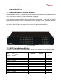
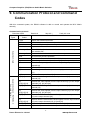
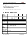
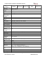
Putron Electronics
VGA Matrix Switchers System
User Manual
MVG Series ---Computer Graphics (VGA)/Stereo Audio Matrix
Please read this manual carefully before using this product.
Notice:
This MVG Matrix Switchers User Manual takes example of the Matrix model
MVG88A. It can be used as user’s manual of other MVG matrix switcher models.
This manual is only an instruction for operators, not for any maintenance usage.
Any changes of functions and parameters since then will be informed separately.
Please refer to the dealers for the latest details.
This manual is copyright PUTRON Electronics Limited. All rights reserved. No
part of this publication may be copied or reproduced without the prior written
consent of PUTRON Electronics Limited.
All product function is valid till 2008-1-1
Computer Graphics (VGA)/Stereo Audio Matrix Switcher
! Safety Operation Guide
In order to ensure the credibility use of the product and the user’s safety, please comply with the
following items during installation and maintenance:
The system must be earthed properly. Please do not use two blades plugs and ensure the alternating
power supply ranged from 100v to 240v and from 50Hz to 60Hz.
Do not put the switcher in a place of too hot or too cold.
To avoid any damage by over heat, please keep the working environment good in ventilation to radiate
the heat when running the switcher.
The switchers should be turned off when in rainy and humid days or nonuse for a long time,
The alternating power supply line should be disconnected with the power socket during the following
operation.
A. Take out or reinstall any component of the switcher
B. Disconnect or re-connect any connector of the switcher
Please do not attempt to maintain and uncover the switcher for there is a high-voltage component
inside and the risk of the electric shock.
Do not splash any chemical product or liquid on or near the equipment.
ii
Putron Electronics Limited
www.putron.com
Computer Graphics (VGA)/Stereo Audio Matrix Switcher
Contents
1. INTRODUCTION ................................................................................................................................ 4
1.1 ABOUT MVG MATRIX SWITCHER SYSTEM ...................................................................................... 4
1.2 MVG MATRIX SWITCHER MODELS ................................................................................................. 4
2. PACKING OF THE PRODUCT .......................................................................................................... 5
3. INSTALLATION ................................................................................................................................. 5
4. FRONT VIEW OF THE PRODUCT .................................................................................................... 6
4.1 FRONT VIEW OF THE MVG44A ...................................................................................................... 6
4.2 FRONT VIEW OF THE MVG82A、MVG84A、MVG88A ................................................................. 6
4.3 FRONT VIEW OF THE MVG164A、MVG168A、MVG1616A ......................................................... 6
5. REAR VIEW OF THE PRODUCT ...................................................................................................... 7
5.1 REAR VIEW OF THE VGA44A ........................................................................................................ 7
5.2 REAR VIEW OF THE WVG8 ............................................................................................................ 7
5.3 REAR VIEW OF THE WVG16、WVG32.......................................................................................... 7
5.4 REAR VIEW OF THE MVG82A、MVG84A、MVG88A ................................................................... 7
5.5 REAR VIEW OF THE MVG164A、MVG168A、MVG1616A ........................................................... 8
6. EXTERNAL CONNECTION ............................................................................................................... 8
6.1 INTRODUCTION OF THE INPUT AND OUTPUT CONNECTORS .............................................................. 8
6.2 CONNECTION OF RS-232 COMMUNICATION PORT .......................................................................... 8
6.2.1 Connection with Control Systems ........................................................................................ 9
6.2.2 Connection with Computer .................................................................................................. 9
6.3 HOW TO CONNECT WITH THE INPUT AND OUTPUT TERMINALS ......................................................... 9
6.4 HOW TO CONNECT WITH THE MVG I/O DEVICES .......................................................................... 11
7. OPERATION OF THE CONTROL PANEL ....................................................................................... 11
7.1 FRONT PANEL DESCRIPTION ....................................................................................................... 11
7.2 COMMAND FORMAT OF THE SWITCHING OPERATION ..................................................................... 11
7.3 EXAMPLES OF OPERATION .......................................................................................................... 12
8. USAGE OF THE REMOTE CONTROLLER .................................................................................... 13
9. COMMUNICATION PROTOCOL AND COMMAND CODES ........................................................... 14
10. TECHNICAL SPECIFICATIONS .................................................................................................... 16
11. TROUBLESHOOTING & MAINTENANCE .................................................................................... 18
iii
Putron Electronics Limited
www.putron.com
Computer Graphics (VGA)/Stereo Audio Matrix Switcher
1. Introduction
1.1
About MVG Matrix Switcher System
MVG series Matrix switcher is a high-performance professional computer and audio signal switcher that
can be used for cross switching of multi computer and audio signal.
MVG series switcher mostly apply in broadcasting TV engineering, multi-media meeting room, big
screen display engineering, television education, command control center or other fields. It provides
power-fail locale protection function, LED indicating, shortcut selecting function. With RS232 interface,
it can be worked with PC, remote control system and any other far-end control system devices . The
user manual takes MVG88 as the example; other models can take reference from it too.
F 1-1 MVG 88A
1.2
MVG Matrix Switcher Models
According to different situation and users, the MVG series can be classified into the following models:
Specifications
Models
Video Inputs
Video
RS232
Outputs
Interface
Audio I/O
MATRIX WVG8A
8
1
√
×
MATRIX WVG16A
16
1
√
×
MATRIX WVG32A
32
1
√
×
MATRIX MVG44A
4
4
√
√
MATRIX MVG82
8
2
√
×
MATRIX MVG82A
8
2
√
√
MATRIX MVG84
8
4
√
×
MATRIX MVG84A
8
4
√
√
MATRIX MVG88
8
8
√
×
MATRIX MVG88A
8
8
√
√
MATRIX MVG164
16
4
√
×
MATRIX MVG164A
16
4
√
√
4
Putron Electronics Limited
www.putron.com
Computer Graphics (VGA)/Stereo Audio Matrix Switcher
Specifications
Models
Video Inputs
Video
RS232
Outputs
Interface
Audio I/O
MATRIX MVG168
16
8
√
×
MATRIX MVG168A
16
8
√
√
2. Packing of the Product
MVG Matrix Host
RS-232 Communication Cord
Power Supply Cord
CD with Application
3. Installation
MVG matrix switchers adopt metal shell and can be stacked with other device. Moreover, they are
rack-mountable enclosure and can be installed in the standard 19” rack.
5
Putron Electronics Limited
www.putron.com
Computer Graphics (VGA)/Stereo Audio Matrix Switcher
F 3-1 Installing the MVG matrix switcher in the standard 19” rack
4. Front View of the Product
4.1
Front View of the MVG44A
F 4-1 Front view of the MVG44A
4.2
Front View of the MVG82A、MVG84A、MVG88A
F 4-4 Front view of the MVG82A、MVG84A、MVG88A
4.3
Front View of the MVG164A、MVG168A、MVG1616A
F 4-5 Front view of the MVG164A、MVG168A、MVG1616A
6
Putron Electronics Limited
www.putron.com
Computer Graphics (VGA)/Stereo Audio Matrix Switcher
5. Rear View of the Product
5.1
Rear View of the VGA44A
F 5-1
5.2
Rear View of the WVG8
F 5-2
5.3
Rear view of the WVG8
Rear View of the WVG16、WVG32
F 5-3
5.4
Rear view of the VGA44A
Rear view of the WVG16,WVG32
Rear View of the MVG82A、MVG84A、MVG88A
F 5-4
Rear view of the MVG82A、MVG84A、MVG88A
7
Putron Electronics Limited
www.putron.com
Computer Graphics (VGA)/Stereo Audio Matrix Switcher
5.5
Rear View of the MVG164A、MVG168A、MVG1616A
F 5-5
Rear view of the MVG164A、MVG168A 、MVG1616A
6. External Connection
6.1
Introduction of the Input and Output Connectors
The MVG matrix switchers adopt female 15-pin HD connectors as the video signal I/O interface, and
captive screw connectors as the audio signal I/O interface. Please refer to the rear view figure of the
model concerned for details.
6.2
Connection of RS-232 Communication Port
Except the front control panel, infrared remote controller (Optional) and the Ethernet control (Optional),
the MVG matrix switcher can be controlled from far-end control systems via the RS-232 communication
port.
This RS-232 communication port is a female 9-pin D connector. The definition of its pins is as the table
below.
Pin
1
2
3
4
5
6
7
8
9
RS-232
N/u
Tx
Rx
N/u
Gnd
N/u
N/u
N/u
N/u
Description
Not used
Transmit data
Receive data
Not used
Signal ground
Not used
Not used
Not used
Not used
8
Putron Electronics Limited
www.putron.com
Computer Graphics (VGA)/Stereo Audio Matrix Switcher
6.2.1
Connection with Control Systems
With the RS-232 port, can control and communicate with the switcher remotely.
6.2.2
Connection with Computer
When the switcher connects to the COM1 or COM2 of the computer with control software, users can
control it by that computer.
To control the switcher, users may use the RS232 software.
Converter
RS-232
Computer for controlling
F 6-1
6.3
Connection between MVG matrix switcher and the computer
How to Connect with the Input and Output Terminals
The MVG matrix switchers may take laptops, desktop computers, graphic workstations and document
cameras as their input signal source, and projectors, RP TVs, displayers and amplifiers as their output
signal destinations.
VGA Connection:
The MVG matrix switchers support all kinds of the RGB and VGA signal sources with 15-PIN HD VGA
connectors.
The 15-PIN HD VGA connector is shown as the figure below.
Pin
RGB
YcbCr
5
1
1
R
Cr
10
15
6
11
2
G
Y
3
B
Cb
4
Not used
5
Ground
6
R ground
Cr ground
7
G ground
Y ground
8
B ground
Cb ground
9
Not used
10
Sync signal ground
11
Not used
12
Not used
13
H or H/V
14
V
15
Not used
F 6-2
15-PIN HD VGA connector
9
Putron Electronics Limited
www.putron.com
Computer Graphics (VGA)/Stereo Audio Matrix Switcher
If the RGB device doesn’t with VGA output terminals, please convert the signals with an RGB to VGA
switcher for getting high quality VGA output effects.
Please use the special VGA signal cord to connect the input and output devices and connect the 15-Pin
HD connectors carefully.
Audio Signal Connection:
Audio connection is little complicated than video. It has two kinds of connection: balanced and
unbalanced.
The balanced connection transmits a pair of balanced signals with two signal cords. Because
interferences will have the same intensity and the opposite phases on the two signal cords, it will be
counteracted in the end. For the low frequency extent of the audio signal, it would be easily interfered
under long distance transmission. Therefore,as an anti-interference connection , it is mostly used in
audio connection of special device.
The unbalanced connection transmits signals only with a signal cord. Without counteraction, it can be
interfered more easily. Accordingly, it is adopted for household appliance or some cases with low
technical demand.
The two kinds of connection are shown below.
Tip
Tip
Sleeve
Sleeves
Tip
Tip
Sleeve
Unbalanced Input
Unbalanced Output
F 6-3
Tip
Ring
Tip
Ring
Sleeves
Tip
Ring
Sleeves
Tip
Ring
Balanced Input
Balanced Output
Balanced/unbalanced connection on captive screw connector
The connection should be selected is up to the interface of the device. When available, the balanced
connection is the first choice. Before connection, please read the command or relevant demand in the
user manual carefully. In some cases, maybe there is balanced in source signal end but unbalanced in
the destination end. If in a nonstandard case, it is done to connect balanced for the balanced end and
unbalanced for unbalanced end. But if in a standard one, the converter must be used to switch the
signals as the same, balanced or unbalanced.
10
Putron Electronics Limited
www.putron.com
Computer Graphics (VGA)/Stereo Audio Matrix Switcher
F 6-4
6.4
Connection of MVG matrix switcher system
How to Connect with the MVG I/O Devices
VGA/VGA signal converter is for the VGA signal source without VGA output ports, such as: desktop
computers and notebooks. It can convert the VGA signals to VGA signals.
F 6-5
Connection of VGA I/O devices
7. Operation of the Control Panel
7.1
Front Panel Description
“AV”
“VIDEO”
“AUDIO”
“1,2,3,4”
7.2
AV synchronal button: To transfer video and audio signal synchronously by the switcher
Example: To transfer both the video and the audio signals from input channel No.3 to
output channel No.4.
Operation: Press buttons in this order “AV”,“3”,, “4””.
Video button: To transfer only video signals from input channel to output channel
Example: To transfer video signals from input channel No.3 to output channel No.4.
Operation: Press buttons in this order “VIDEO”, “3”, “4”.
Audio button: To transfer only audio signals from input channel to output channel
Example: To transfer audio signals from input channel No.2 to output channel No.3.
Operation: Press buttons in this order ““AUDIO”, “2”, “3””.
I/O Keypads: Keys to select I/O channels.
Example: To transfer input channel No.3 to output channel No.1
Operation: Press buttons in this order : “3” in INPUT area, “1” in OUTPUT area.
Command Format of the Switching Operation
With the front control panel, the switcher could be control directly and rapidly by pressing the buttons
under below format.
“Menu” +“Input Channel” +“Output Channel 1”
“Menu”: “AV”, “Audio”, “Video”
“Input Channel”: Fill with the number of input channel to be controlled
“Output Channel”: Fill with the number of output channels to be controlled
11
Putron Electronics Limited
www.putron.com
Computer Graphics (VGA)/Stereo Audio Matrix Switcher
7.3
Examples of Operation
Example 1:To transfer video and audio signals from input channel No.1 to output channel
No.3,4
AV
Video
Audio
1, Press the button for switching mode “AV” for the switching mode of video
and audio (“Audio” for the switching mode of audio only; “Video” for the
switching mode of video only)
1
2
3
4
2, Press the button for input channel number“1”
2
3
3,Press the button for the first output channel number “3”
4
4, Press the button for the second output channel number “4”
2
3
4
Then, switching OK !
audio/video switching from “1” to “3” and “4”
12
Putron Electronics Limited
www.putron.com
Computer Graphics (VGA)/Stereo Audio Matrix Switcher
8. Usage of the Remote Controller
With the infrared remote controller, the matrix switcher could be control remotely. Because the function
buttons on the remote controller are the same with the ones on the front control panel, the remote
controller shares the same control operation and command format with the control panel. P
The inputs
channels, from
0~9, and
plusing “10+”
for more
Menu, for
switching
source and
function
The outputs
channels, from
0~9, and
plusing “10+”
for more
13
Putron Electronics Limited
www.putron.com
Computer Graphics (VGA)/Stereo Audio Matrix Switcher
9. Communication Protocol and Command
Codes
With this command system, the RS232 software is able to control and operate the MCV Matrix
remotely.
Communication protocol:
Baud rate: 9600
Command
Types
Data bit: 8
Stop bit: 1
Command
Codes
Parity bit: none
Functions
System Command
Operation Command (PUTRON2.0
Command System)
/*Type;
Inquire the models information.
/%Lock;
Lock the keyboard of the control panel on the Matrix.
/%Unlock;
Unlock the keyboard of the control panel on the Matrix.
/^Version;
Inquire the version of firmware
/:MessageOff;
Turn off the feedback command from the com port. It will only show
the “switcher OK”.
/:MessageOn;
Turn on the feedback command from the com port.
Undo.
To cancel the previous operation.
Demo.
Switch to the “demo” mode, 1->1, 2->2, 3->3 … and so on.
[x1]All.
Transfer signals from the input channel [x1] to all output channels
All#.
Transfer all input signals to the corresponding output channels
respectively.
All$.
Switch off all the output channels.
[x1]#.
Transfer signals from the input channel [x1] to the output channel
[x1].
[x1]$.
Switch off the output channel [x1].
[x1] V[x2].
Transfer the video signals from the input channel [x1] to the output
channel [x2].
[x1]
V[x2],[x3],[x4].
Transfer the video signals from the input channel [x1] to the output
channels [x2], [x3] and [x4].
[x1] A[x2].
Transfer the audio signals from the input channel [x1] to the output
channel [x2].
[x1]
A[x2],[x3],[x4].
Transfer the audio signals from the input channel [x1] to the output
channels [x2], [x3] and [x4].
[x1] B[x2].
Transfer both the video and the audio signals from the input channel
[x1] to the output channel [x2].
[x1]
B[x2],[x3],[x4].
Transfer both the video and the audio signals from the input channel
[x1] to the output channels [x2], [x3] and [x4].
Status[x1].
Inquire the input channel to the output channel [x1].
Status.
Inquire the input channel to the output channels one by one.
14
Putron Electronics Limited
www.putron.com
Computer Graphics (VGA)/Stereo Audio Matrix Switcher
Save[Y].
Save the present operation to the preset command [Y]. [Y] ranges
from 0 to 9.
Recall[Y].
Recall the preset command [Y].
Clear[Y].
Clear the preset command [Y].
Note:
1. [x1], [x2], [x3] and [x4] are the symbols of input or output channels ranged according to the
model of the matrix switcher. If the symbols exceed the effective range, it would be taken as a
wrong command.
2. In above commands, “[”and “]” are symbols for easy reading and do not need to be typed in
actual operation.
3. Please remember to end the commands with the ending symbols “.” and “;”.
Detail Examples:
1、 Transfer signals from an input channel to all output channels: [x1]All.
Example: To transfer signals from the input channel No.3 to all output channels.
“3All.”
Run Command:
2、 Transfer all input signals to the corresponding output channels respectively: All#.
Example: If this command is carried out on an MVG1616-A matrix switcher, the status of it will be:
1->1, 2->2, 3->3, 4->4……16->16.
3、 Switch off all the output channels: All$.
Example: After running this command, there will be no signals on all the output channels.
4、 Check the version of the firmware: /^Version;
To check the version of the firmware.
5、 Switch off the detail feedback command from the COM port: /:MessageOff;
Switch off the detail feedback information from the COM port. But, it will leave the “switch OK” as
the feedback, when you switch the matrix.
6、 Switch on the detail feedback command from the COM port: /:MessageOn;
Switch on the detail feedback information from the COM port. it will show the detail switch
information when it switch. Example: when switch 1->2 for Audio, it will feedback “A0102”.
7、 Transfer signals from an input channel to the corresponding output channel: [x]#.
Example: To transfer signals from the input channel No.5 to the output channel No.5. Run
Command: “5#.”
8、Switch off an output channel: [x]$.
Example: To switch off the output channel No.5. Run Command: “5$.”
9、Switch video signals command: [x1] V[x2].
Example: To transfer the video signals from the input channel No.3 to the output channel No.5.
Run Command: “3V5.”
10、Switch audio signals command: [x1] A[x2].
Example: To Transfer the audio signals from the input channel No.10 to the output channel
Run Command: “10A2.”
11、Switch both video and audio signals synchronously: [x1] B[x2].
Example: To transfer both the video and the audio signals from the input channel No.120 to the
output channel No.12,13,15. Run Command: “120B12,13,15.”
12、Inquire the input channel to the output channel [x]: Status[x].
15
Putron Electronics Limited
www.putron.com
Computer Graphics (VGA)/Stereo Audio Matrix Switcher
Example: To inquire the input channel to the output channel No.23. Run Command: “Status23.”
13、Inquire the input channel to the output channels one by one: Status.
Example: To inquire the input channel to the output channels one by one. Run Command:
“Status.”
14、Save the present operation to the preset command [Y]: Save[Y].
Example: To save the present operation to the preset command No.7. Run Command: “Save7.”
15、Recall the preset command [Y]: Recall[Y].
Example: To recall the preset command No.5. Run Command: “Recall5.”
16、Clear the preset command [Y]: Clear[Y].
Example: To clear the preset command No.5. Run Command: “Clear5.”
10. Technical Specifications
Series
MVG44A
MVG8 series
MVG16 series
WVG8
WVG32 series
Specifications
Video
MVG44A
Models
included
MVG82A
MVG84A
MVG88A
MVG164A
MVG168A
WVG8
WVG32
WVG 64
WVG 96
Gain
0 dB
Bandwidth
250MHz (-3dB), fully loaded
Cross talk sum
-60dB @10 MHz, -39dB @100 MHz
Switching speed
200 ns (Max)
Signal type
VGA,VGAS, RGsB, RsGsBs, HDTV, Component video,S-video, Composite
video
Input video
Connector
Female 15-pin HD
Signal strength
1V p-p Y component video、S-video,composite video; 0.7V p-p
R-Y & B-Y component video、 S-video
Maximum/Minimu
m level
Analog signals: 0.5V ~ 2.0V p-p
Impedance
75 Ω
Echo loss
<-40dB@5MHz
Horizontal
frequency response
15 kHz ~ 145 kHz
Vertical frequency
response
30 Hz ~ 170 Hz
Max error in DC
offset
15mV
VGA;0.3V p-p
Output video
16
Putron Electronics Limited
www.putron.com
Computer Graphics (VGA)/Stereo Audio Matrix Switcher
Series
MVG44A
MVG8 series
MVG16 series
WVG8
WVG32 series
Specifications
Connector
Female 15-pin HD
Maximum/Minimu
m level
2.0V p-p
Impedance
75 Ω
Echo loss
<-40dB@5MHz
Max
compensation
Dc offset
±5mV
in
Sync signal
Input/output
signals
RGBHV, RGBS, RGsB, RsGsBs, Component video, Composite video
Video system
NTSC 3.58,NTSC 4.43,PAL,SECAM
Input level
0.5V- 5.0V p-p,: 4.0V p-p normal
Output level
AGC-TTL: 5Vp-p, unterminated
Input impedance
510 Ω
Output impedance
75 Ω
Maximum
transmission delay
Horizontal:90ns
Maximum
ascending/descendi
ng time
4ns
Polarity
Straight or subtractive according to input
Vertical:160ns
Audio signal
I/O connector
3.8mm with screw , 5 pole
Gain
0dB
Frequency
respond
20 Hz ~ 20 kHz,
General harmonic
distortion + noise
0.05% @ 1 kHz (under rating voltage)
S/N
>90dB
Segregation rate
>80dB @ 1 kHz
CMRR
>75dB @: 20 Hz ~ 20 kHz
Signal
Stereo ,balanced /unbalanced
Impedance
Input:>10 kΩ(balanced /unbalanced)
Output:50 Ω (unbalanced), 100 Ω(balanced)
Maximum
level
input
+19.5dBu, (balanced /unbalanced)
Gain error
±0.1dB @20 Hz ~ 20 kHz
Max output level
+19.5dBu, (balanced /unbalanced)
Control type
17
Putron Electronics Limited
www.putron.com
Computer Graphics (VGA)/Stereo Audio Matrix Switcher
Series
MVG44A
MVG8 series
MVG16 series
WVG8
WVG32 series
Specifications
Serial control port
RS-232, 9-pin FD connector
Baud rate
protocol
Baud rate: 9600
and
Data bit: 8 Stop bit: 1
Serial
control
poling protocol
2 = TX, 3 = RX, 5 = GND
Control
application
Switch 2.0
Parity bit: none
Features
Power supply
100VAC ~ 240VAC, 50/60 Hz, universal international power supply
Temperature
Storing and operating temperature: -20° ~ +70°C
Humidity
Storing and operating humidity: 10% ~ 90%
Size
485(L)X245(W
)X445mm(H)
485(L)X260(W
)X90mm(H)
485(L)X260(W
)X140mm(H)
485(L)X245(W
)X445mm(H)
485(L)X260(W
)X90mm(H)
weight
1.8kg
3.5kg
4.3kg
1.8kg
3.5kg
MTBF
30,000 hours
Quality guarantee
1 year free guarantee
11. Troubleshooting & Maintenance
1)
When the output image in the destination device connected to the MVG Matrix has ghost, such as
the projector output with ghost, please check the projector’s setting or try another high quality
connection cord.
2)
When there is a color losing or no video signal output, it may be the unmatched VGA connector
order between the input and output end.
3)
When the remote controller doesn’t works:
A. Maybe the battery is run out of, please change a new one.
B. Maybe the controller is broken, please ask the dealer to fix it.
4)
When user can not control the MVG Matrix by computer through its COM port, please check the
COM port number in the software and make sure the COM port is in good condition.
5)
When switching , the beeper beeps but without any output image:
A. Check with oscilloscope or multimeter if there is any signal at the input end. If there is no
signal input, it may be the input connection cord broken or the connectors loosen.
B. Check with oscilloscope or multimeter if there is any signal at the output end. If there is no
signal output, it may be the output connection cord broken or the connectors loosen.
C. Please make sure the destination device is exactly on the controlled output channel
18
Putron Electronics Limited
www.putron.com
Computer Graphics (VGA)/Stereo Audio Matrix Switcher
D.
If it is still the same after the above checking, it may be something wrong in the switcher.
Please send it to the dealer for fixing.
6)
If the output image is interfered, please make sure the system is earthed well.
7)
If the static becomes stronger when connecting the BNC connectors, it may be due to the incorrect
earthing of the power supply, Please earth it again correctly, and otherwise it would bring damage
to the switcher or shorten its natural life.
8)
If the Matrix can not be controlled by the keys on the front panel, RS232 port or remote controller,
the host may has already been broken. Please send it to the dealer for fixing.
19
Putron Electronics Limited
www.putron.com