1
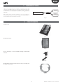
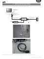
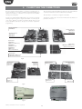
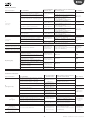
humiSet Humidifier Programming Tool User manual NO POWER & SIGNAL CABLES TOGETHER READ CAREFULLY IN THE TEXT! Integrated Control Solutions & Energy Savings ENG WARNINGS WARNINGS NO POWER & SIGNAL CABLES TOGETHER READ CAREFULLY IN THE TEXT! CAREL bases the development of its products on decades of experience in HVAC, on the continuous investments in technological innovations to products, procedures and strict quality processes with in-circuit and functional testing on 100% of its products, and on the most innovative production technology available on the market. CAREL and its subsidiaries nonetheless cannot guarantee that all the aspects of the product and the software included with the product respond to the requirements of the final application, despite the product being developed according to start-of-theart techniques. The customer (manufacturer, developer or installer of the final equipment) accepts all liability and risk relating to the configuration of the product in order to reach the expected results in relation to the specific final installation and/or equipment. CAREL may, based on specific agreements, acts as a consultant for the positive commissioning of the final unit/application, however in no case does it accept liability for the correct operation of the final equipment/system. The CAREL product is a state-of-the-art device, whose operation is specified in the technical documentation supplied with the product or can be downloaded, even prior to purchase, from the website www.carel.com. Each CAREL product, in relation to its advanced level of technology, requires setup/configuration/programming/commissioning to be able to operate in the best possible way for the specific application. The failure to complete such operations, which are required/indicated in the user manual, may cause the final product to malfunction; CAREL accepts no liability in such cases. Only qualified personnel may install or carry out technical service on the product. The customer must only use the product in the manner described in the documentation relating to the product. In addition to observing any further warnings described in this manual, the following warnings must be heeded for all CAREL products • prevent the electronic circuits from getting wet. Rain, humidity and all types of liquids or condensate contain corrosive minerals that may damage the electronic circuits. In any case, the product should be used or stored in environments that comply with the temperature and humidity limits specified in the manual. • do not install the device in particularly hot environments. Too high temperatures may reduce the life of electronic devices, damage them and deform or melt the plastic parts. In any case, the product should be used or stored in environments that comply with the temperature and humidity limits specified in the manual. • do not attempt to open the device in any way other than described in the manual. • do not drop, hit or shake the device, as the internal circuits and mechanisms may be irreparably damaged. • do not use corrosive chemicals, solvents or aggressive detergents to clean the device. • do not use the product for applications other than those specified in the technical manual. Separate as much as possible the probe and digital input signal cables from the cables carrying inductive loads and power cables to avoid possible electromagnetic disturbance. Never run power cables (including the electrical panel wiring) and signal cables in the same conduits. DISPOSAL The product is made up of metal parts and plastic parts. In reference to European Union directive 2002/96/EC issued on 27 January 2003 and the related national legislation, please note that:: 1. WEEE cannot be disposed of as municipal waste and such waste must be collected and disposed of separately; 2. the public or private waste collection systems defined by local legislation must be used. In addition, the equipment can be returned to the distributor at the end of its working life when buying new equipment; 3. the equipment may contain hazardous substances: the improper use or incorrect disposal of such may have negative effects on human health and on the environment; 4. the symbol (crossed-out wheeled bin) shown on the product or on the packaging and on the instruction sheet indicates that the equipment has been introduced onto the market after 13 August 2005 and that it must be disposed of separately; 5. in the event of illegal disposal of electrical and electronic waste, the penalties are specified by local waste disposal legislation. All of the above suggestions likewise apply to the controllers, serial boards, programming keys or any other accessory in the CAREL product portfolio. CAREL adopts a policy of continual development. Consequently, CAREL reserves the right to make changes and improvements to any product described in this document without prior warning. The technical specifications shown in the manual may be changed without prior warning. The liability of CAREL in relation to its products is specified in the CAREL general contract conditions, available on the website www.carel.com and/or by specific agreements with customers; specifically, to the extent where allowed by applicable legislation, in no case will CAREL, its employees or subsidiaries be liable for any lost earnings or sales, losses of data and information, costs of replacement goods or services, damage to things or people, downtime or any direct, indirect, incidental, actual, punitive, exemplary, special or consequential damage of any kind whatsoever, whether contractual, extra-contractual or due to negligence, or any other liabilities deriving from the installation, use or impossibility to use the product, even if CAREL or its subsidiaries are warned of the possibility of such damage. 3 humiSet +030220311 - rel. 2.2 - 01.09.2014 ENG humiSet +030220311 - rel. 2.2 - 01.09.2014 4 ENG Content 1. INTRODUCTION 7 2. COMPONENTS 7 3. INSTALLING THE HARDWARE 9 4. CLASSIFYING THE CONNECTIONS 10 5. ON-BOARD CONNECTIONS 12 5.1 Type A connection ........................................................................................ 12 5.2 Type B connection ........................................................................................ 12 5.3 Type C connection ........................................................................................ 13 6. OFF-BOARD CONNECTIONS (“ON THE TABLE”) 14 6.1 Type D connection....................................................................................... 14 6.2 Type E connection......................................................................................... 14 6.3 Type F connection ......................................................................................... 14 6.4 Type G connection....................................................................................... 15 6.5 Type H connection ....................................................................................... 15 7. INSTALLING THE SOFTWARE 7.1 7.2 7.3 7.4 16 Installing humiSet under Windows 7 (32 bit/64 bit) ............................ 16 Installazione di humiSet su Windows 8 ....................................................17 Installing Windows 8 on humiSet .............................................................17 Changing the default serial port (COM1) ................................................17 8. USING THE SOFTWARE 18 8.1 Programming with humiSet........................................................................ 18 9. STOPPING HUMISET 21 5 humiSet +030220311 - rel. 2.2 - 01.09.2014 ENG 1. INTRODUCTION CAREL have developed a kit —humiSet— intended for both OEM customers and CAREL branches. It contains all the HW & SW parts and components necessary to program any of CAREL controllers for any type of humidifier for series humiSteam, heaterSteam, humiFog, gaSteam, kit OEM “KUE”. Umidifcatori Humidifiers Cliente/OEM/Filiale Customer/OEM/Carel Sales Office humiSet Controllore Controller With humiSet and a Personal Computer, the user can program (i.e. download the parameters needed to configure the humidifier) both onboard and off-board (“on-the-table”) controllers. (”on the table”) Fig. 1.a 2. COMPONENTS Installation CD Fig. 2.a RS232-485 Converter Fig. 2.b 230 Vac (50/60Hz) / 12 Vac transformer feeding the RS232-485 Converter Fig. 2.c RS232 Cable for connection between the PC serial port (output) and the RS232-485 Converter Fig. 2.d 7 humiSet +030220311 - rel. 2.2 - 01.09.2014 ENG 9 pin plug/ 25 pin female-terminal serial adapter for PC with 25 pin output Fig. 2.e HPI (Humidifier Programming Interface) adapter Note: HPI must be powered only by the supplied transformer (figure 8) or by a transformer featuring an output 24 Vac protected against the short circuits. Fig. 2.f 230 VAC (50/60Hz) / 24 VAC transformer with (1x faston connector and 1x plug-in connector) for the HPI adapter feeding “Boardcontroller” controllers (see below) Fig. 2.g 3-to-4-pole communication cable with plug-in connectors for connection to RS232-RS485 Converter as an HPI adapter, or directly to either the humidifier or “Boardcontroller” RS485 - NETWORK CVSTDUMOR0 UEX CPY*2* CPY*0*/ CPY*1* RS485 - Humivisor Fig. 2.h Flat communication cable for connection between the HPI & “Boardcontroller” (for type UM*******, UE***P**** & KUE******* humidifiers, see table 2) Fig. 2.i Flat cable for connection between the HPI & Humicontrol Fig. 2.j USB-RS485 Converter (CVSTDUMOR0) Fig. 2.k humiSet +030220311 - rel. 2.2 - 01.09.2014 8 ENG 3. INSTALLING THE HARDWARE CAREL supplies a complete hardware kit -humiSet- common to all controllers. The kit parts to be used for configuring the controller will vary depending on the circumstances. Figure 3.a - 3.b - 3.c show the standard kit installation, which is common in all cases. connettore seriale serial connector adattatore 9poli-25poli (solo per PC con 25 connettore seriale a 25 poli) 9pole-25pole adapter (only for PC with 25 serial connectors 25-pole) Convertitore Converter Cavo RS232 / RS232 cable 230 Vac Cavo 3poli-4poli 3pole-4pole cable 12 Vac Fig. 3.a Fig. 3.b Fig. 3.c The hardware connections must be completed according to the circumstances, as described in detail in the following paragraphs. 9 humiSet +030220311 - rel. 2.2 - 01.09.2014 ENG 4. CLASSIFYING THE CONNECTIONS We have already mentioned that it is possible to program both onboard controllers (i.e., controllers assembled in finished humidifiers) and off-board controllers (i.e., controllers not connected to the humidifier, namely, put “on the table”). Table 4.a refers to finished humidifiers and lists the codes of the different controllers and interface boards assembled in the humidifiers. To help you to understand the different types of connections, it is worth referring to Figure 14, Figure 15, Figure 16, and tables 1 & 2. They list the codes of the different controllers and Interface Boards that are used for the humidifiers, and refer to the type of connection required for programming. The letters in column “Type of Connection” indicate the classification of particular connections. Table 4.b refers to controllers to configure “on the table”. Scheda interfaccia 98C474C005 Scheda interfaccia 98C460C006 98C460C002 Scheda interfaccia 98C474C004 98C474C002 humicontrol 98C460C001 (URH*******, URS*******) 98C474C001 (UEH/UEA*******) 98C486C004 (UGH*******) humicontrol 98C493C001 (UAH*******) vedi etich. lato inferiore vedi etich. lato inferiore humicontrol 98C460C003 (URC*******) vedi etich. lato inferiore Fig. 4.d Boardcontroller 98C489C002, 98C489C012 (UES*******) Boardcontroller CP4******* Boardcontroller CP1******* Boardcontroller 98C489C003, 98C489C013 (UMC*******) Boardcontroller 98C489C001, 98C489C011 (UEP*******) Boardcontroller CP2******* Boardcontroller CP3******* Fig. 4.e Fig. 4.f humiSet +030220311 - rel. 2.2 - 01.09.2014 Fig. 4.g 10 ENG Finished humidifiers Type of connection Type of Humidifier Price-list Humidifier/ CAREL production code (on interface board Type of display Controller codes and controller labels) With immersed electrodes “humiSteam” – humidity Umidif: UE***H**** regulation (rated production <= 15 kg/h) Controll: UEH*******, With immersed electrodes “humiSteam” - humidity UEA******* regulation (rated production >= 25 kg/h) A (see Fig. 5.a, 5.b e 5.c) With heaters “heaterSteam” – humidity regulation Umidif: UR***H**** Controll: URH******* With heaters “heaterSteam” – ON/OFF Umidif: UR***C**** Controll: URC******* With heaters “heaterSteam” – temperature regulation (Turkish baths) Umidif: UR***T**** Controll: URS******* With atomisation “humiFog” Umidif: UA***H**** Controll: UAH******* With gas “gaSteam” Umidif: UG***H**** Controll: UGH******* Immersed electrodes “humiSteam” – proport-ON/ Umidif: UE***P**** OFF regulation (rated production <= 15 kg/h) Immersed electrodes “humiSteam” – proportioControll: UEP******* nal-ON/OFF regulation (rated production >= 25 kg/h) Umidif: UM***C**** Immersed electrodes “homeSteam” Controll: UMC******* B (see Fig. 5.d, 5.e e 5.f ) if without serial option card TACP485000: B (see fig. 20, 21, 22) Immersed electrodes OEM “KUE” if with serial option card TACP485000: C (see fig. 23, 24, 25) H (see Fig. 6.e ) Immersed electrodes “humiSteam X-PLUS” - (rated production <= 18 kg/h) Immersed electrodes “humiSteam X-PLUS - (rated production >= 25 kg/h) Immersed electrodes “humiSteam WELLNESS” (rated production <= 18 kg/h) Immersed electrodes “humiSteam WELLNESS” (rated production >= 25 kg/h) Immersed electrodes “humiSteam BASIC” - (rated production <= 18 kg/h) Immersed electrodes “humiSteam BASIC” - (rated production >= 25 kg/h) KUE Immersed electrodes OEM “KUE” Int: 98C474C005 (uscita seriale disponibile) Controll: 98C474C001 (Humicontrol) Int: 98C460C006 o 98C460C002 (uscita seriale disponibile) Controll: 98C460C001 (Humicontrol) Int: 98C460C006 o 98C460C002 (uscita seriale disponibile) Controll: 98C460C003 (Humicontrol) Int: 98C460C006 o 98C460C002 (uscita seriale disponibile) Controll: 98C460C001 (Humicontrol) Int: 98C460C006 o 98C460C002 (uscita seriale disponibile) Controll: 98C493C001 (Humicontrol) Int: 98C460C006 o 98C460C002 (uscita seriale disponibile) Controll: 98C486C004 (Humicontrol) Humicontrol, DIGIT version Humicontrol LED version Humicontrol DIGIT version 98C489C001 o 98C489C011 (Boardcontroller) (uscita seriale non disponibile) 3-LED DISPLAY 98C489C002 o 98C489C012 (Boardcontroller) (red, yellow & (uscita seriale non disponibile) green) 98C489C003 o 98C489C013 Boardcontroller) (uscita seriale non disponibile) Umidif: KUE******* Controll: CP******** (Boardcontroller) CP******** (Boardcontroller) 3-LED DISPLAY (uscita seriale disponibile se montata opzione (red, yellow & scheda seriale TACP485000) green) Umidif: UE***X**** Controll: UEX******* UEX******* PGD1 Umidif: UE***W**** UEW*****10 Controll: UEW*****10 PGD1 Umidif: UE***Y**** Controll: UEY******* UEY******* HCT Umidif: KUE******* Controll: CPY******* CPY******* CPYTERM Tab. 4.a Controllers “on the table” Type of connection Type of Humidifier Price-list Humidifier/ Controller codes CAREL production code (on interface board and controller labels) With immersed electrodes “humiSteam” - humidity regulation (rated production <= 15 kg/h) With immersed electrodes “humiSteam” - humidity regulation (rated production >= 25 kg/h) Umidif: UE***H**** Controll: UEH*******, UEA******* Immersed electrodes OEM “KUE” Umidif: UR***H**** Controll: URH******* Umidif: UR***C**** Controll: URC******* Umidif: UR***T**** Controll: URS******* Umidif: UA***H**** Controll: UAH******* Umidif: UG***H**** Controll: UGH******* With heaters “heaterSteam” – humidity regulation D (see Fig. 6.a e 6.b) With heaters “heaterSteam” – ON/OFF With heaters “heaterSteam” – temperature regulation (Turkish baths) With atomisation “humiFog” With gas “gaSteam” E (see Fig. 6.c) 98C474C001 (Humicontrol) 98C460C001 (Humicontrol) 98C460C003 (Humicontrol) Humicontrol LED version 98C460C001 (Humicontrol) 98C493C001 (Humicontrol) Humicontrol DIGIT version 98C486C004 (Humicontrol) Umidif: UM***C**** Controll: UMC******* 98C489C001 o 98C489C011 (Boardcontroller) (serial port unavailable) 98C489C002 o 98C489C012 (Boardcontroller) (serial port unavailable) 98C489C003 o 98C489C013 Boardcontroller) (serial port unavailable) 3-LED DISPLAY (red, yellow & green) Umidif: KUE******* Controll: CP******** (Boardcontroller) CP******** (Boardcontroller) (serial port available if with serial option card TACP485000) 3-LED DISPLAY (red, yellow & green) Immersed electrodes “humiSteam” – proportional-ON/OFF regulation (rated production <= 15 kg/h) Immersed electrodes “humiSteam” – proportional-ON/OFF regulation (rated production >= 25 kg/h) Umidif: UE***P**** Controll: UEP******* Immersed electrodes “homeSteam” if without serial option card TACP485000: B (see figure 29) Immersed electrodes OEM “KUE” if with serial option card TACP485000: C (see figure 30) Type of display Tab. 4.b 11 humiSet +030220311 - rel. 2.2 - 01.09.2014 ENG 5. ON-BOARD CONNECTIONS 5.1 Type A connection RACK cavo 3poli-4poli 3 to 4 pin cable After completing the standard installation (see Figure 13), connect the 3-to-4-pole cable to the Interface Board inside the humidifier rack, as shown in Figure 17, Figure 18, and Figure 19. Scheda interfaccia Interface board 24 Vdc + GND Note: With this type of connection, the precondition to program the controller is that the humidifier must be “on”. Precondition: since the board is installed on a finished humidifier, the controller programming can be performed only if the humidifier is “on”. Humicontrol Fig. 5.a Fig. 5.b 5.2 Type B connection The “Boardcontroller” controller used with this kind of connection has no serial port. Use the black 10-pin female terminal in the middle of the board instead. To make the connection, use the Humidifier Programming Interface (HPI, Figure 7) and the flat cable (Figure 10) for connection between the HPI and the electronic board, as shown in Figure 20. Fig. 5.c Pay the utmost attention to the direction of insertion of the flat cable connector into the board: the HPI adapter might fail if the direction is wrong. To avoid ambiguity, the flat communication cable is made so that, if the direction is wrong, it can be easily noticed that the connector stroke is hampered by the electrolytic condenser near the black 10-pole female terminal (see Figure 21 & Figure 22). cavo 3poli-4poli 3 to 4 pin cable RACK Boardcontroller Cavo flat / Flat cable HPI Fig. 5.d VISTA LATERALE SIDE VIEW condensatori elettrolitici electrolitic capacitances direzione corretta per l’inserimento del cavo flat right direction for insertion of flat cable connettore 10 pin femmina 10 pins female connector Boardcontroller Fig. 5.e humiSet +030220311 - rel. 2.2 - 01.09.2014 12 ENG Precondition: since the board is installed on a finished humidifier, the controller programming can be performed only if the humidifier is “on”. Fig. 5.f 5.3 Type C connection The “Boardcontroller” controller of the humidifiers requiring this kind of connection do not have any default serial port. However, a small option card (code TACP485000) can be installed to allow serial connection by the green 3-pole connector on the controller. RACK Boardcontroller As with example A, plug the 3-to-4-pole connector in the “Boardcontroller” controller. Unlike Interface Boards, in this case the output connector has 3 poles. Care must be taken when plugging the 3-to-4-pole cable connector (see Figure 23, Figure 24, and Figure 25). + - REF cavo 3poli-4poli 3 to 4 pin cable Precondition: since the board is installed on a finished humidifier, the controller programming can be performed only if the humidifier is “on”. Fig. 5.g scheda opzionale TACP485000 inserita TACP485000 optional serial card NOT INSERTED Attenzione alla posizione del connettore Look at right connector position Fig. 5.h Fig. 5.i 13 humiSet +030220311 - rel. 2.2 - 01.09.2014 ENG 6. OFF-BOARD CONNECTIONS (“ON THE TABLE”) In this case, the programming concerns controllers not electrically connected to the humidifier. As a result, a special installation is required for connection to both the HPI and the 230VAC/24VAC transformer necessary to feed the system. 6.1 HPI Cavo flat / Flat cable cavo 3poli-4poli 3 to 4 pin cable Type D connection connettori Faston Faston connections Humicontrols can be programmed directly, without using the Interface board. In this case, it is necessary to use the HPI (Figure 7), the 230 Vac/24 Vac transformer for HPI feeding (Figure 8), and the flat cable for connection between the l’HPI and the controller “on the table” (Figure 10), as shown in Figure 26 and Figure 27. 230 Vac inserzione con connettore maschio Male and female insertion connector Humicontrol 24 Vac Fig. 6.a Fig. 6.b 6.2 Type E connection Any of “Boardcontroller” controllers can be programmed directly even if it is not connected to the humidifier. In this case, you need: • the HPI (Figure 7); • the flat cable for connection between the HPI and Boardcontroller (Figure 10); • the 230 Vac/24 Vac transformer (Figure 8) for feeding Boardcontroller controller in terminals G-G0 through the faston connector (Figure 28). Note: in this case, the HPI does not need to be fed at 24 Vac. Precondition: the board can be programmed only if it is powered on. Fig. 6.c 6.3 Type F connection The “Boardcontroller” controller can be programmed directly even if it is not connected to the humidifier and the serial option card TACP485000 is not installed. In this case, you need: • the HPI (Figure 7); • the flat cable for connection between the HPI and Boardcontroller (Figure 10); • the 230 Vac/24 Vac transformer (Figure 8) for feeding Boardcontroller controller in terminals G-G0 through the plug-in connector (Figure 29). Note: in this case, the HPI does not need to be fed at 24 Vac. Fig. 6.c-a Precondition: the board can be programmed only if it is powered on. humiSet +030220311 - rel. 2.2 - 01.09.2014 14 ENG 6.4 Type G connection The “Boardcontroller” controller can be programmed directly even if it is not connected to the humidifier and the serial option card TACP485000 is installed. In this case, you need the 230 Vac/24 Vac transformer (Figure 8) for feeding “Boardcontroller” controller in terminals G-G0 through the plugin connector (Fig. 6.d). Precondition: the board can be programmed only if it is powered. Unlike Interface Boards, in this case the output connector has 3 poles. Care must be taken when plugging the 3-to-4-pole cable connector (see Fig. 5.g e Fig. 5.h). Fig. 6.d 6.5 Type H connection The controller can be programmed directly, using the USB-RS485 CVS CONVERTER even if it is not connected to the humidifier In this case, you need the 230 Vac/24 Vac transformer (Fig. 2.g) for feeding controller in terminals G-G0 through the plug-in connector (Fig. 6.d). Convertitore USB-RS485 morsetto 3 vie Precondition: the board can be programmed only if it is powered. Note: Unlike Interface Boards, in this case the output connector has 3 poles. It must be chosen carefully according to the controller to be programmed. G0-G Convertitore USB-RS485 morsetto 3 vie G0-G Convertitore USBRS485 morsetto 3 vie Fig. 6.e 15 humiSet +030220311 - rel. 2.2 - 01.09.2014 ENG 7. INSTALLING THE SOFTWARE 8. Install the RS232-RS485 driver for USB-RS485 converter (available Please, refer to the “Readme.txt” file in the CD-ROM for installing humiSet up to Windows XP operative system. Conditions necessary for the operation of humiSet: • to be PC-administrator; • close all programs that use port 80 (example Skype); • Set Internet Explorer as the default browser; • install the latest version of Java available without Ask Toolbar. from ksa.carel.com). Fig. 7.d 7.1 Installing humiSet under Windows 7 (32 bit/64 bit) 9. 10. 11. 12. 13. 1. Type “UAC” (User Account Control) into search command line 2. Put the switch down (“Never notify”) and click OK (Warning: you may Right click on the Dbase “20110307.exe”: choose Preferences Click now to the “Compability”-Tab Select “use program in compatibility mode” Select in the pull-down menu “Windows XP Service Pack 3” Also “run program as admin” and OK need admin-rights) Fig. 7.e Fig. 7.a 14. Run “20110307.exe” now (double click). Info: It may takes some 3. Restart Windows 4. Download from ksa.carel.com “20030417-cd_HUMISET000.zip” and 15. 16. 17. 18. 19. 20. 21. unzip it. 5. Install humiSet by double-clicking on “humisetup.exe” minutes… Close all Oracle applications Create a Shortcut of humiSet (maybe on your desktop) Right click on it: choose Preferences Click now to the “Compability”-Tab Select “use program in compatibility mode” Select in the pull-down menu “Windows XP Service Pack 3” Also “run program as admin” and OK Fig. 7.b 6. Download “humiSet_patch_names.zip” from ksa.carel.com and install it 7. Copy Dbase “20110307.exe” (or the latest available from ksa.carel. com) into the humiset folder (default C:\Program Files (x86)\Carel\ humiSet) Fig. 7.f 22. Before starting humiSet, set the usb port number if other than default COM1 is used. 23. In order to know COM n° to which USB-RS485 converter is connected, from folder “Computer”, click on “System properties”. Fig. 7.c humiSet +030220311 - rel. 2.2 - 01.09.2014 16 ENG 28. Save and exit the file “driver.ini” 29. Double-click now on the humiset-shortcut (start the program) 30. If you use a firewall – allow to run humiSet 7.2 Installing Windows 8 on humiSet Additionally as specified in paragraph 7.1 for Windows 7, the Windows 8 operating system requires an additional setting. After installing the latest version of Java without Ask Toolbar, from the control panel to access Java, enter security modification sites list and add the following addresses: • http://127.0.0.1 • http://localhost Fig. 7.g 24. Click on “Devices management” Fig. 7.h Fig. 7.j Press OK to confirm. 25. Click on “Ports (COM e LPT)”, then read the usb port to which the device USB-RS485 converter is connected. For example, COM 4. Note: test performed on the operating system Windows 8.1 Pro 7.3 Changing the default serial port (COM1) If a serial port other than default COM1 is required, proceed as described below (after installing the software). Find folder Carel \ humiSet \ data \ nodes \ node0 from folder “Programs”; Identify file “driver.ini” and open it by using a text editor (e.g. NOTEPAD for Windows): The text below will be displayed: [config] MaxRetry485=3 Line1=1,4,485 Line2= Line3= Line4= Line5= Line6= The third line: Fig. 7.i 26. Find folder “Carel \ humiSet \ data \ nodes \ node0 from folder “Programs (x86)”, identify the file “driver.ini” and open it by using a text editor (e.g. NOTEPAD for Windows) 27. The text below will be displayed: [config] MaxRetry485=3 Line1=1,4,485 Line2= Line3= Line4= Line5= Line6= The third line 1 Line1= ,4,485 contains the number identifying COM1 (figure 1 in bold). To select COM2 you just have to modify the line as shown below: 2 Line1= ,4,485 Make sure you have not changed anything else, then click on exit to leave. You will be asked whether you want to save the changes. Answer “yes”. If humiSet was already active, it might be possible to go on using the system without restarting it. Should problems occur, restart humiSet. 1 Line1= ,4,485 contains the number identifying COM1 (1 in bold). To select COM4 you just have to modify the line as shown below: 4 Line1= ,4,485 As you are using a usb port instead of a serial port, do the following modification too: Line1= 4,4,485_232 17 humiSet +030220311 - rel. 2.2 - 01.09.2014 ENG 8. USING THE SOFTWARE 8.1 Programming with humiSet In this case, check both connections and feeding, then press “Retry”. The precondition for programming to start is prior connection of all hardware devices, as indicated in the previous paragraphs. • If the communication is active, the following page will be displayed (Fig. 8.c): Now the controllers can be programmed. Once the installation of the software is completed, the icon below will be displayed: • Click twice on it to start running humiSet software. A similar, smaller icon will be displayed in the bottom right-hand corner of the application bar: Internet Explorer will be triggered, and the following home page will be displayed (Fig. 8.a): Fig. 8.c 1. Draw the mouse on the first coloured bar “Controller/humidifier”, and 2. 3. 4. 5. 6. Fig. 8.a Press “OK”. press the left button of the mouse: a list of options will be displayed. Here choose the controller category depending on the humidifier to which the controller is associated. After making the first choice, select “Controller type”. Choose according to the type of controller installed on the humidifier. Refer to tables 1 & 2, and to Figure 14, Figure 15 and Figure 16. The third option concerns the rated production (kg/h of the humidifier where the controller must be installed). The fourth option is about the Voltage of the humidifier where the controller must be installed, or its constructive options. The fifth option concerns the possible customised variations. The sixth option is about possible controller versions required for particular humidifier versions. This option is provided for future expansions; at present, there is no particular version. The selection of the controller associated with the humidifier will be over when no menu asks “Please select:” any more. Each message “Please select:” means an item that has not been selected yet. The selection is organised in such a way that, once an option is selected, the following ones will give only options consistent with the previously selected ones. • In case of trouble with any connection or with the feeding, the application will display the following error page (Fig. 8.b): However, it is the operator’s responsibility to check the consistency of the controller programming selected and the type of humidifier where the controller must be installed. Be careful! • After selecting the last field, a Pop Up Window will display the code of the set of parameters to apply during the programming. It is the same code that must be used to request the programmed spare controller. Press key OK in the Pop Window (Fig. 8.d). Then, the key “Ok” in the bottom left-hand corner will turn active. Press “Ok” to continue. The system will check the consistency of the choices made with the controller firmware. Fig. 8.b humiSet +030220311 - rel. 2.2 - 01.09.2014 18 ENG • If humiSet does not contain the required set of parameters, the following error page will be displayed (Fig. 8.g): Fig. 8.d Fig. 8.g • If the consistency is confirmed, then a window indicating that everything is ready for parameter downloading will be displayed (Fig. 8.e): In this case: • The connected controller might not suit the option selected; check controller and replace it with a suitable one; refer to tables 4.a and 4.b and to Fig. 4.a, 4.b e 4.c. or: • The firmware in the controller might be more recent than the database in humiSet; In this case, it is possible to find the updated database for the new versions of the controller firmware in http://ksa.carel.com as shown in the of Fig. 8.c, or contact directly Carel. Anyway, we suggest checking carefully the previous points. • Conversely, if the communication between humiSet and the controller is broken, the following page will be displayed (Fig. 8.h): Fig. 8.e • If the consistency is not confirmed, then the option made does not suit the controller connected: for instance, a humidifier like “humiSteam” type H is selected, and the firmware for the management of humidifier “KUE*******” is stored, the following error page will be displayed (Fig. 8.f ): Fig. 8.h Once page “Ready for the download” (Fig. 8.e) is displayed, press “Download” to continue. Great attention must be given to the fact that the controller must not be replaced while this page is displayed, either before or after pressing Download. Otherwise, the programming might be affected by errors that are not detected by humiSet. If the controller has to be replaced before pressing “Download”, you must necessarily press “Back to ‘Selection of the Controller’”. Fig. 8.f 19 humiSet +030220311 - rel. 2.2 - 01.09.2014 ENG • If the programming is performed correctly, the following page will be • If, after completion of the programming, the page below is displayed, displayed (Fig. 8.i): check connections and repeat the programming (Fig. 8.l): Fig. 8.l Fig. 8.i • The following page might be displayed during utilization of humiSet (Fig. 8.m): Certain data for completion of the operations are provided for certain types of controllers. Check them for correctness on the humidifier. • In case of trouble during the writing of certain parameters, the page below will be displayed (Fig. 8.j): Fig. 8.m Press “Retry” to continue. So, the points above listed the steps to follow for programming the parameters of controllers. Now, they are ready and can be used to manage the humidifier appropriately. Fig. 8.j If the trouble persists at the following attempt, then the controller might be faulty. Replace it as necessary. Note: “Boardcontroller” controllers with firmware release 14 or earlier are not programmable while they are showing the firmware release (at power-on, flashes of yellow and red led). Humicontrol controllers are not programmable during the first 5 seconds from power-on (until “---“ is shown). If Fig. 8.j, appears, retry only after these events. • Likewise, the following page might be displayed (Fig. 8.k): Fig. 8.k If the trouble persists at the following attempt, then the controller might be faulty. Replace it as necessary. humiSet +030220311 - rel. 2.2 - 01.09.2014 20 ENG 9. STOPPING HUMISET On completion of the controller programming, Internet Explorer can be exited. However, it is worth noting that the icon below is still in the application bar: . As long as the icon is there, just trigger Internet Explorer and enter http:// localhost + ENTER to restart humiSet. When humiSet is exited, we suggest closing the icon as well. To do this, draw the pointer arrow on the icon in the application bar . then: • Press the right button of the mouse • Select “Close” Note: humiSet cannot remain active non-stop for more than 20 hours. If this limit is exceeded, the page below might be displayed (Fig. 9.a): Fig. 9.a Just stop humiSet and start it up again. 21 humiSet +030220311 - rel. 2.2 - 01.09.2014 ENG humiSet +030220311 - rel. 2.2 - 01.09.2014 22 CAREL INDUSTRIES - Headquarters Via dell’Industria, 11 - 35020 Brugine - Padova (Italy) Tel. (+39) 049.9716611 - Fax (+39) 049.9716600 e-mail: [email protected] - www.carel.com humiSet +030220311 - rel. 2.2 - 01.09.2014 Agenzia / Agency: