1
Distributed Doodling
Daniel Burrell, Mike Gist, Jan Hosang, Dave Lawrence, Andrew Slater
January 15, 2009
1
Abstract
Communications for the business and academic world is increasingly
taking to the digital highways of the internet. As yet though, there is no
easy way for a group of peers to collaborate together on a design project
involving diagrams being analysed and reworked. This project addresses
that issue in attempting to create a distributed system that allows a group
of people to connect over the internet and collaborate on a drawing.
The construction of the Tabula application was the result of the Distributed Doodling project. The application aims to provide the desired
chat and drawing solution for collaborations by multiple users. To aid
the construction of the application, the Qt framework was chosen to support the GUI development while RakNet was found to provide the desired
network functionality. Qt provides many useful widgets that greatly simplified development and the signals and slots system creates an easy to use
method for connection possible user actions (pressing a button for example) to a function. RakNet provides permits for the layering of some TCP
like features over a UDP connection, greatly reducing the overheads that
would have been associated with using TCP. Overall the architecture has
been designed to be highly extensible in anticipation of future functionality
being added.
Custom ‘Events’ have been designed to represent actions of the user;
this may include drawing an object or sending a text chat message. To
keep a record of these Event objects a logging system has been developed
which uses a unique logical timestamp system to allow every Event to be
identified and ordered. This uses vectors of logical timestamps to identify
each system and avoid local clock synchronisation issues. A user action
will cause the logical clock in that users system to tick with other users
system clocks being updated when they receive the Event. So that sessions
can be saved and restored, XML is used to save the history of the session
to hard disk.
Live drawing was an interesting addition to the application, allowing
users to see other members of the conversation drawing in real time. This
also allowed us to take full advantage of the optional TCP like features on
the UDP connection that was being used. Temporary events allow users to
see objects being manipulated remotely however if a few of these are lost
of arrive out of order, it is not important. Therefore, for these temporary
events we were able to use a standard UDP connection, again lowering the
necessary bandwidth. A peer to peer network system is built ontop of our
enhanced UDP connection, creating a robust connection between all peers
with the ability to reconnect peers if an intermediate system fails.
The application provides a solution that has not previously existed.
Testing on the log system shows that it is able to operate faster than a
high speed network can deliver events from multiple users. The application
has been a success as far as reaching the key, and many of the advanced
requirements are concerned. There remain some advanced requirements
that could be implemented and there are highly complex features that
could be added that were always considered beyond the goals of the project.
The GUI may be considered a ‘contractual GUI’ in that it looks very simple
and minimal and possibly work by a professional designer could help it look
more appealing.
2
Contents
Contents
3
1 Introduction
1.1 Motivation . . . . . . . . . . . .
1.2 Requirements . . . . . . . . . . .
1.2.1 Key Requirements . . . .
1.2.2 Advanced Requirements .
1.3 Use Case Diagram . . . . . . . .
1.4 Similar Solutions . . . . . . . . .
1.4.1 Windows Live Messenger
1.4.2 Windows Journal . . . . .
1.4.3 iScribble . . . . . . . . . .
1.4.4 Conclusions . . . . . . . .
2 Tools and Frameworks Used
2.1 Qt . . . . . . . . . . . . . . . .
2.1.1 Widgets . . . . . . . . .
2.1.2 Signals & Slots . . . . .
2.1.3 GUI Support . . . . . .
2.1.4 Issues and Quirks . . . .
2.1.5 Justification . . . . . . .
2.2 RakNet . . . . . . . . . . . . .
2.2.1 TCP vs UDP . . . . . .
2.2.2 Reliability and Ordering
2.2.3 BitStreams . . . . . . .
2.2.4 VOIP Support . . . . .
2.2.5 Justification . . . . . . .
.
.
.
.
.
.
.
.
.
.
.
.
.
.
.
.
.
.
.
.
.
.
.
.
.
.
.
.
.
.
.
.
.
.
3 Architecture & Design
3.1 System Overview . . . . . . . . . .
3.1.1 Model View Controller . . .
3.2 The Log Subsystem . . . . . . . .
3.2.1 The Live Log . . . . . . . .
3.2.2 XML Logging to Disk . . .
3.3 Chat Subsystem . . . . . . . . . .
3.4 Board Subsystem . . . . . . . . . .
3.4.1 Overall structure . . . . . .
3.4.2 View . . . . . . . . . . . . .
3.4.3 Scene/Model . . . . . . . .
3.4.4 Graphic Items . . . . . . .
3.4.5 Identifying Graphical Items
3.4.6 Casting . . . . . . . . . . .
3.4.7 Drawing Contexts . . . . .
3.4.8 Factory Within Contexts .
3
.
.
.
.
.
.
.
.
.
.
.
.
.
.
.
.
.
.
.
.
.
.
.
.
.
.
.
.
.
.
.
.
.
.
.
.
.
.
.
.
.
.
.
.
.
.
.
.
.
.
.
.
.
.
.
.
.
.
.
.
.
.
.
.
.
.
.
.
.
.
.
.
.
.
.
.
.
.
.
.
.
.
.
.
.
.
.
.
.
.
.
.
.
.
.
.
.
.
.
.
.
.
.
.
.
.
.
.
.
.
.
.
.
.
.
.
.
.
.
.
.
.
.
.
.
.
.
.
.
.
.
.
.
.
.
.
.
.
.
.
.
.
.
.
.
.
.
.
.
.
.
.
.
.
.
.
.
.
.
.
.
.
.
.
.
.
.
.
.
.
.
.
.
.
.
.
.
.
.
.
.
.
.
.
.
.
.
.
.
.
.
.
.
.
.
.
.
.
.
.
.
.
.
.
.
.
.
.
.
.
.
.
.
.
.
.
.
.
.
.
.
.
.
.
.
.
.
.
.
.
.
.
.
.
.
.
.
.
.
.
.
.
.
.
.
.
.
.
.
.
.
.
.
.
.
.
.
.
.
.
.
.
.
.
.
.
.
.
.
.
.
.
.
.
.
.
.
.
.
.
.
.
.
.
.
.
.
.
.
.
.
.
.
.
.
.
.
.
.
.
.
.
.
.
.
.
.
.
.
.
.
.
.
.
.
.
.
.
.
.
.
.
.
.
.
.
.
.
.
.
.
.
.
.
.
.
.
.
.
.
.
.
.
.
.
.
.
.
.
.
.
.
.
.
.
.
.
.
.
.
.
.
.
.
.
.
.
.
.
.
.
.
.
.
.
.
.
.
.
.
.
.
.
.
.
.
.
.
.
.
.
.
.
.
.
.
.
.
.
.
.
.
.
.
.
.
.
.
.
.
.
.
.
.
.
.
.
.
.
.
.
.
.
.
.
.
.
.
.
.
.
.
.
.
.
.
.
.
.
.
.
.
.
.
.
.
.
.
.
.
.
.
.
.
.
.
.
.
.
.
.
.
.
.
.
.
.
.
.
.
.
.
.
.
.
.
.
.
.
.
.
.
.
.
.
.
.
.
.
.
.
.
.
.
.
.
.
.
.
.
.
.
.
.
.
.
.
.
.
.
.
.
.
.
.
.
.
.
.
.
.
.
.
.
.
.
.
.
.
.
.
.
.
.
.
.
.
.
.
.
.
.
.
.
.
.
.
.
.
.
.
.
.
.
.
.
.
.
.
.
.
.
.
.
.
.
.
.
.
.
.
.
.
.
.
.
.
.
.
.
.
.
.
.
.
.
.
.
.
.
.
.
.
.
.
.
.
.
.
.
.
.
6
6
6
6
7
8
8
8
10
11
12
.
.
.
.
.
.
.
.
.
.
.
.
13
13
13
13
13
14
14
16
16
16
17
17
17
.
.
.
.
.
.
.
.
.
.
.
.
.
.
.
19
19
19
20
20
23
24
25
25
26
26
26
26
28
28
29
3.5
3.6
3.7
3.4.9 Executing Board Events . .
3.4.10 Calling Order . . . . . . . .
Network Subsystem . . . . . . . .
3.5.1 Serialisation . . . . . . . . .
3.5.2 Session . . . . . . . . . . .
3.5.3 Session View . . . . . . . .
3.5.4 Session Model . . . . . . . .
GUI Design . . . . . . . . . . . . .
Exporting to Image File . . . . . .
3.7.1 JPG/JPEG Plugin Issue . .
3.7.2 Implementation . . . . . . .
3.7.3 Right-click Context Menus
4 Timestamps
4.1 Requirements . . .
4.2 Ordering of Events
4.3 Logical Time . . .
4.4 Vector Clocks . . .
4.5 Implementation . .
.
.
.
.
.
.
.
.
.
.
.
.
.
.
.
.
.
.
.
.
.
.
.
.
.
.
.
.
.
.
.
.
.
.
.
.
.
.
.
.
.
.
.
.
.
.
.
.
.
.
.
.
.
.
.
.
.
.
.
.
.
.
.
.
.
.
.
.
.
.
.
.
.
.
.
.
.
.
.
.
.
.
.
.
.
.
.
.
.
.
.
.
.
.
.
.
.
.
.
.
.
.
.
.
.
.
.
.
.
.
.
.
.
.
.
.
.
.
.
.
.
.
.
.
.
.
.
.
.
.
.
.
.
.
.
.
.
.
.
.
.
.
.
.
.
.
.
.
.
.
.
.
.
.
.
.
.
.
.
.
.
.
.
.
.
.
.
.
.
.
.
.
.
.
.
.
.
.
.
.
.
.
.
.
.
.
.
.
.
.
.
.
.
.
.
.
.
.
.
.
.
.
.
.
29
30
31
31
31
32
32
33
34
34
35
35
.
.
.
.
.
.
.
.
.
.
.
.
.
.
.
.
.
.
.
.
.
.
.
.
.
.
.
.
.
.
.
.
.
.
.
.
.
.
.
.
.
.
.
.
.
.
.
.
.
.
.
.
.
.
.
.
.
.
.
.
.
.
.
.
.
.
.
.
.
.
.
.
.
.
.
.
.
.
.
.
.
.
.
.
.
.
.
.
.
.
.
.
.
.
.
.
.
.
.
.
.
.
.
.
.
.
.
.
.
.
.
.
.
.
.
37
37
37
38
39
40
5 The Log
5.1 Events . . . . . . . . . . .
5.1.1 Chat Events . . .
5.1.2 Draw Events . . .
5.1.3 Modify Events . .
5.1.4 Delete Events . . .
5.1.5 Temporary Events
5.2 Adding Events . . . . . .
5.3 Event Jumping . . . . . .
5.4 Optimisations . . . . . . .
5.5 Serialisation . . . . . . . .
.
.
.
.
.
.
.
.
.
.
.
.
.
.
.
.
.
.
.
.
.
.
.
.
.
.
.
.
.
.
.
.
.
.
.
.
.
.
.
.
.
.
.
.
.
.
.
.
.
.
.
.
.
.
.
.
.
.
.
.
.
.
.
.
.
.
.
.
.
.
.
.
.
.
.
.
.
.
.
.
.
.
.
.
.
.
.
.
.
.
.
.
.
.
.
.
.
.
.
.
.
.
.
.
.
.
.
.
.
.
.
.
.
.
.
.
.
.
.
.
.
.
.
.
.
.
.
.
.
.
.
.
.
.
.
.
.
.
.
.
.
.
.
.
.
.
.
.
.
.
.
.
.
.
.
.
.
.
.
.
.
.
.
.
.
.
.
.
.
.
.
.
.
.
.
.
.
.
.
.
.
.
.
.
.
.
.
.
.
.
.
.
.
.
.
.
.
.
.
.
.
.
.
.
.
.
.
.
.
.
.
.
.
.
.
.
.
.
.
.
44
44
44
44
45
45
45
45
45
46
46
6 Network
6.1 Network Topology . . . . . . . . . . . . .
6.1.1 Structure . . . . . . . . . . . . . .
6.1.2 NAT Punch-through . . . . . . . .
6.1.3 Reconnects . . . . . . . . . . . . .
6.1.4 Ordering Streams and Priority . .
6.2 Network Implementation . . . . . . . . . .
6.2.1 Subscribers . . . . . . . . . . . . .
6.2.2 Serialisation . . . . . . . . . . . . .
6.2.3 Sessions . . . . . . . . . . . . . . .
6.2.4 Authentication and Compatibility
6.2.5 Assigning of Unique ID . . . . . .
.
.
.
.
.
.
.
.
.
.
.
.
.
.
.
.
.
.
.
.
.
.
.
.
.
.
.
.
.
.
.
.
.
.
.
.
.
.
.
.
.
.
.
.
.
.
.
.
.
.
.
.
.
.
.
.
.
.
.
.
.
.
.
.
.
.
.
.
.
.
.
.
.
.
.
.
.
.
.
.
.
.
.
.
.
.
.
.
.
.
.
.
.
.
.
.
.
.
.
.
.
.
.
.
.
.
.
.
.
.
.
.
.
.
.
.
.
.
.
.
.
.
.
.
.
.
.
.
.
.
.
.
.
.
.
.
.
.
.
.
.
.
.
48
48
48
48
49
49
50
50
51
51
51
52
.
.
.
.
.
.
.
.
.
.
.
.
.
.
.
4
7 Evaluation
7.1 Comparison With Initial Requirements
7.1.1 Completed Requirements . . .
7.1.2 Dropped Requirements . . . . .
7.1.3 Additional Features . . . . . .
7.2 Usability . . . . . . . . . . . . . . . . .
7.2.1 GUI . . . . . . . . . . . . . . .
7.2.2 Learning Curve . . . . . . . . .
7.3 Architecture & Design . . . . . . . . .
7.3.1 Software Engineering Patterns
7.3.2 Tug of War . . . . . . . . . . .
7.4 Choice of Languages & Tools . . . . .
7.4.1 C++ . . . . . . . . . . . . . . .
7.4.2 Qt . . . . . . . . . . . . . . . .
7.4.3 Jam . . . . . . . . . . . . . . .
7.4.4 Raknet . . . . . . . . . . . . .
7.5 Benchmarks . . . . . . . . . . . . . . .
7.5.1 Performance of the Log . . . .
7.5.2 Performance of the Network . .
7.6 Statistics . . . . . . . . . . . . . . . .
8 Conclusions
8.1 Time Management . . . . . . . . . .
8.2 Software Engineering Patterns . . .
8.3 Use of Frameworks . . . . . . . . . .
8.4 Future Work . . . . . . . . . . . . .
8.4.1 Drawing Functionality . . . .
8.4.2 Chat . . . . . . . . . . . . . .
8.4.3 How to Add an Operation . .
8.4.4 Increased Collaboration . . .
8.4.5 Custom Shapes and Graphics
8.4.6 GUI Improvements . . . . . .
.
.
.
.
.
.
.
.
.
.
.
.
.
.
.
.
.
.
.
.
.
.
.
.
.
.
.
.
.
.
.
.
.
.
.
.
.
.
.
.
.
.
.
.
.
.
.
.
.
.
.
.
.
.
.
.
.
.
.
.
.
.
.
.
.
.
.
.
.
.
.
.
.
.
.
.
.
.
.
.
.
.
.
.
.
.
.
.
.
.
.
.
.
.
.
.
.
.
.
.
.
.
.
.
.
.
.
.
.
.
.
.
.
.
.
.
.
.
.
.
.
.
.
.
.
.
.
.
.
.
.
.
.
.
.
.
.
.
.
.
.
.
.
.
.
.
.
.
.
.
.
.
.
.
.
.
.
.
.
.
.
.
.
.
.
.
.
.
.
.
.
.
.
.
.
.
.
.
.
.
.
.
.
.
.
.
.
.
.
.
.
.
.
.
.
.
.
.
.
.
.
.
.
.
.
.
.
.
.
.
.
.
.
.
.
.
.
.
.
.
.
.
.
.
.
.
.
.
.
.
.
.
.
.
.
.
.
.
.
.
.
.
.
.
.
.
.
54
54
54
55
56
56
56
57
58
59
60
60
60
61
62
62
63
63
64
64
. . . .
. . . .
. . . .
. . . .
. . . .
. . . .
. . . .
. . . .
Packs
. . . .
.
.
.
.
.
.
.
.
.
.
.
.
.
.
.
.
.
.
.
.
.
.
.
.
.
.
.
.
.
.
.
.
.
.
.
.
.
.
.
.
.
.
.
.
.
.
.
.
.
.
.
.
.
.
.
.
.
.
.
.
.
.
.
.
.
.
.
.
.
.
.
.
.
.
.
.
.
.
.
.
.
.
.
.
.
.
.
.
.
.
.
.
.
.
.
.
.
.
.
.
.
.
.
.
.
.
.
.
.
.
.
.
.
.
.
.
.
.
.
.
65
65
66
66
67
67
67
67
69
69
70
.
.
.
.
.
.
.
.
.
.
.
.
.
.
.
.
.
.
.
.
.
.
.
.
.
.
.
.
.
.
.
.
.
.
.
.
.
.
Glossary
72
References
74
5
1
Introduction
1.1
Motivation
A picture is worth a thousand words. Often quick sketches can be used to
explain a concept much more concisely than words ever could. However, there
has always been a problem with drawing and sending such pictures easily and
efficiently over the Internet. As the Internet is quickly replacing conventional
meetings and provides many benefits, such as removing the costs of travel and
time, it is becoming ever more important for a functional distributed drawing
solution.
Our project, Tabula, aims to fill this gap that commercial software has left
in the online communication and collaboration fields. There are many existing systems that provide either online messaging or drawing features, including
Windows Live Messenger or iScribble, however these are primarily instant messaging systems with a drawing application added for fun. We aim to provide an
application which focuses on the problem of many users attempting to collaborate in areas where diagrams are the primary method of communicating ideas
and constructs.
We have approached this problem in collaboration with our project supervisor Professor S. Drossopoulou, our initial target user, who wishes to use this
application in her research field.
1.2
Requirements
We chose a set of requirements which we feel will produce a highly productive
and feature rich initial release of Tabula. These requirements were reached from
interviews with our project supervisor, comparison with existing projects (Section 1.4) and features which the group believed would provide a more immersive
tool.
1.2.1
Key Requirements
Collaborative Drawing: The ability for multiple users to draw on the same
canvas at the same time.
Distributed: Operates over a network without a dedicated server machine.
Text Chat: An instant messenger client allowing for text based communication between whiteboard contributors.
Freeform drawing: The ability to draw freely on the canvas with a pen-style
tool.
Object Repositioning: Allow users to reposition elements once they have
been placed on the canvas.
Vector Resizing: Freeform object resizing whilst maintaining precision, unlike raster graphics.
6
Text Labels: Addition of text to the canvas
These basic requirements are what the final solution requires to be a productive tool. The most complicated of these requirements will be the implementation of the distributed elements of the solution.
1.2.2
Advanced Requirements
Logging: Provides functionality for recording a session, allowing for playback
or undo/redo actions.
Version control: Allows users to go back through the log and branch the
diagram.
Joining of a session after it has started: Update anyone that joins with
the entire session log and current version of the whiteboard.
Save and resume sessions: The ability to stop and continue drawing sessions at a later date with full history and versioning.
Click and drag-to-size polygon palette: A palette of common polygons that
can be selected, placed and resized in a single action.
Permissions on drawing: Set sections of the canvas to be non-editable by
others.
Export diagram as image: Allow the user to send a fixed version of the
whiteboard to any person in an image format.
Audio chat: Provides a more immersive experience than text chat, to be integrated into our logging system.
Tabbed canvases: Multiple canvases within a single whiteboard session for
separation of drawings and ideas.
Layered canvas: Set the order in which objects are to be drawn onto the
canvas.
Auto-correction of lines: Simplifies freeform drawing by correcting basic input errors.
Shape Recognition: Detect and replace objects that appear close to triangles, square, circles and basic shapes as these are hard to draw accurately
with any input device.
These advanced requirements will increase the appeal of Tabula to a wider
audience of users by increasing core functionality, improving accessibility to
novice users and extending the areas of use for the application from the original
specification.
7
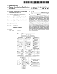
1.3
Use Case Diagram
Figure 1: Use case diagram for a Distributed Doodling based application modeled in
UML
The main functionality and purpose of Tabula should be to enable collaboration, reviewing and archiving of diagrams as part of a greater research goal.
This results in the requirements of having a session and sending / receiving
messages and drawn objects; the ability to resume sessions at a later date and
ultimately to archive the result of a collaboration in a more standard format
such as an image file.
1.4
Similar Solutions
There are a number of solutions available that provide parts of our desired
solution. We compare these applications against our requirements in Table 1.
These solutions are typically applications developed for Tablet PCs which have
been extended to normal PC usage by replacing the pen with a mouse cursor.
Freeform drawing with a mouse is a very unnatural and imprecise method of
input resulting in poorly formed shapes.
1.4.1
Windows Live Messenger
The closest standalone application available is the widely used[29] Windows
Live Messenger[27] which has the ability to draw simple pictures and send them
within a group conversation. However there are a number of issues with this
solution.
Messenger is historically a chat based Instant Messaging system[30] to which
the ability to speak, draw, play games and such have been added. Thus the main
8
Feature
Collaborative Drawing
Distributed
Text Chat
Freeform Drawing
Object Repositioning
Vector Resizing
Text Labels
Logging
Version Control
Joining of Existing Session
Save & Restore
Polygon Palette
Permissions on Drawing
Export Diagram as Image
Audio Chat
Tabbed Canvases
Layered Canvas
Auto-correction of Lines
Shape Recognition
Continuous Editing
Live Drawing
Live Messenger
%
"
"
"
%
%
%
"
%
No History
%
%
%
%
"
%
%
%
%
%
%
Journal
%
%
%
"
"
"
"
Undo/Redo
%
N/A
"
%
%
"
%
Multi-instance
%
%
%
"
N/A
iScribble
"
"
"
"
%
%
%
%
%
"
%
%
%
%
%
Multi-instance
"
%
%
"
"
Table 1: A comparison of existing software, each of which provide part of our desired
functionality, against the final Tabula release.
9
Tabula
"
"
"
"
"
"
"
"
"
"
"
"
"
"
%
Multi-instance
"
%
%
"
"
focus of Messenger is text based conversation and this results in poor drawing
integration. As can be seen in Figure 2, the default proportions between text
and drawing are biased towards text conversation; drawing can only be accessed
from within a special tab in the chat entry box, thus a user cannot draw and
chat at the same time. The only input method is freeform drawing using a
Tablet PC pen or mouse pointer - shapes cannot be selected from a palette.
Figure 2: Windows Live Messenger v14.0 showing small drawing space and inability
to re-edit sent images. Note standard freeform drawing errors: jagged lines,
points not meeting and lack of ability to send text whilst drawing. Right
graphics shows drawing once sent, it cannot be edited.
Most importantly, the drawing feature does not include the ability for another user to modify the drawing and return it. The concept of multiple users
modifying the same drawing is one of the fundamental goals of the project and
therefore the lack of this ability in Windows Live Messenger severely limits its
use as a viable option.
1.4.2
Windows Journal
Windows Journal[35] is a notepad tool developed for Tablet PCs released with
Windows XP Tablet PC Edition. It provides the user with a canvas, typically
with ruled or grid lines, upon which the user is able to scribble notes and
diagrams. This can then be saved to file or exported as an image. If saved in
the Journal format, it can be re-opened and editing can continue.
Windows Journal provides freeform drawing and the ability to select and
resize objects once drawn. However, Windows Journal is an offline application
with no messaging facilities which is also hampered by Microsoft’s support for
the product. As it has been developed for a Tablet PC, the writer application
is only available on Windows XP Tablet PC Edition and Windows Vista; older
versions of Windows (2000, XP and Server 2003) only have a reader application
available[26].
Windows Journal does offer several advanced features to Tablet PC users,
these include handwriting recognition and the ability to dynamically insert vertical space into a document. We believe that handwriting recognition would be
10
Figure 3: Windows Journal v6.0 showing the ability to draw and type on the same
canvas. Note the lack of pre-defined shapes for mouse entry.
of benefit to many users, however we feel this to be beyond of the scope of this
project and recommend it as a possible extension.
1.4.3
iScribble
iScribble[14] is the closest application to the problem that the team has found.
It is a browser based application running on Adobe Flash and therefore is cross
platform and only requires installation of the Flash Player, a standard browser
plugin with a 99.0% install base[4].
iScribble provides an interface consisting of a canvas with simple tools for
lines and circles, a standard text chat interface and a layer panel. It also features
a highly customisable pen tool with adjustable thickness and full colour palette.
Drawing sessions take place in “Rooms” which can be set to public or private
upon creation.
Figure 4: iScribble.net public room showing a user friendly interface and clearly defined options.
The main weaknesses of iScribble lie in the inability to save and review the
session at a later point whilst also lacking a way to export the image from
the application. There is no user accessible log of the drawing construction,
however the application itself runs on a logging system. This can be seen when
11
entering a room as the various layers and objects are drawn onto the canvas.
Due to this non accessible log iScribble does not support modification once a
draw action has occurred; hence it features no selection, delete, move or undo
tools.
iScribble relies heavily on users having a graphics tablet or Tablet PC as the
only built in shape is a straight line - all other shapes must be drawn freehand.
Users are also not able to put text labels on drawings. If any labels are required
they may be drawn using the free-form drawing functionality of iScribble, in a
similar way to Windows Live Messenger.
Finally, unlike the other similar solutions reviewed, iScribble is an Internet
application hosted on a 3rd party. This results in no guarantee of security
or privacy when using iScribble. There is also a limitation on the types of
drawings that can be created on iScribble as its main intention is to create
artistic imagery, this is enforced via a terms of use agreement and an account
banning system[13].
1.4.4
Conclusions
The project is looking to create a combination of these applications for the
standard keyboard and mouse input system. Ideally there should be similar chat
functionality to Windows Live Messenger combined with the natural freedom
to draw provided by Windows Journal and iScribble. The failings of not being
able to draw standard shapes is an area that will specifically be covered by our
application.
12
2
Tools and Frameworks Used
2.1
Qt
Qt is a cross-platform application framework[34] which is widely used in both
commercial applications and open source projects. It provides a comprehensive modular framework for developing Graphical User Interface (GUI)
applications. Many well known applications have been developed using Qt including Google Earth, Skype and Adobe Photoshop Album[33]. Over the last
decade it has cemented its position as the diamond standard C++ framework
for cross-platform software development[31].
2.1.1
Widgets
Qt provides a large range of standard widgets that we used to create the
GUI. These widgets include everything from simple push buttons to graphical canvases and sliders for fine grained selection. Layout managers were used
to arrange the widgets and also perform automatic positioning and resizing
depending on the contents or window size. These widgets support the Model
View Controller Pattern (MVC), a pattern we adopted frequently throughout the project which is further discussed in Section 3.1.1
2.1.2
Signals & Slots
One of the most important features of Qt is the way it handles input from the
GUI. When a widget is used it emits a signal, for example a button may emit
a ‘clicked’ signal. The developer can then choose to connect a signal with some
action by creating the appropriate method, called a ‘slot’, then connecting the
signal to the slot by calling Qt’s connect() function.
The connections between signals and slots are very flexible; the signals can
be dynamically remapped to different slots at any point during execution. They
are implemented in standard C++ using the C++ preprocessor and the Meta
Object Compiler (MOC) that is included with Qt. MOC reads the header
files and automatically generates the necessary code to support the signals and
slots mechanism. Qt gives you the choice of using a provided compiler (QMake)
to compile all code and automatically run MOC where required. However we
manually ran the MOC tool on our header files since we were using the VC++
third party compiler.
Connections can also be made between objects in different threads. Although not directly used within our project we believe this would be a useful
feature for future extensibility. For example, this could be used in conjunction
with processor intensive extensions such as handwriting recognition which needs
to process data as it’s created without reducing the application’s response time.
2.1.3
GUI Support
Often in modern GUIs there will be a number of ways to perform the same
function. For example, we have a ‘save’ menu option and key combination
13
(Ctrl + S) which perform the same action. If we later decide to implement a
toolbar button this would be trivial to hook into the same handler. Qt supports
the ability to have multiple triggers for the same function by way of the QAction
class. This ensures that wherever an action is invoked from, the states of the
different elements stay in sync. Therefore, if an action is disabled both its menu
and toolbar selectors will be disabled.
All the standard features of a modern GUI are supported in Qt. The QMainWindow class provides the framework for a normal application window. The
QMenuBar provided the standard style menu bar which we populated with our
own choice of commands.
2.1.4
Issues and Quirks
In providing the modularity and flexibility of a large number of standardised
widgets, Qt poses some unexpected issues. Qt typically has widgets consisting of
either a default implementation which can be inherited and methods overridden
or an abstract class with pure virtual methods which must be implemented.
In particular, the QGraphics system provides us with several basic shapes,
primarily QEllipseItem, QRectItem, QLine, QPath. These classes are part of
the Qt library and are totally closed for modification. Modifying these objects
directly in order to extend them would be a non trivial task as it would have a
ripple effect through classes we don’t use and would make the task of upgrading
the library with new releases difficult.
Instead we extended these classes to add functionality to them, then we
casted down from QGrahpicItem type to our extended type since it is not possible to produce what we refer to as the ‘Diamond’ pattern as shown in Figure 5.
This is because we cannot use virtual multiple inheritance since this would also
require access to the Qt classes, we deal with the solution to this in Section 3.4.6
but suffice to say that the class responsible for casting is encapsulated and isolated as much as possible.
It should be noted throughout the rest of this report that all classes prefixed
with a Q are Qt classes implemented for us which we use directly, extend or
override, but cannot modify. We highlight these as shown in Figure 6(a). In
addition, class diagrams will contain classes displaying only their name, these
are to indicate a link to other diagrams where they are shown in greater detail,
these are identified as per Figure 6(b)
2.1.5
Justification
Qt provides both Java and C++ implementations of its framework. Therefore
it presented itself as a good choice in the very early stages of the design process
as it was not dependent on which of these two languages was eventually chosen.
It was also very important that the framework was provided as open source.
There should not be any license issues with using the framework regardless of
how widely used an application becomes.
Although Qt does provide a certain amount of networking functionality, in
terms of the project requirements this was the main weakness of the library.
14
Figure 5: Lines indicate inheritance, note the line from DGraphicItem to
QGraphicItem doesn’t exist in our implementation.
(a) Qt classes represented via hatching. These are uneditable.
(b)
Borderline
classes. These are
detailed in other
class diagrams.
Figure 6: Examples of custom UML representations used within our class diagrams.
15
Instead we sought out an alternative networking library, RakNet.
There are no real alternatives to the entire Qt package as it provides a fully
featured framework and a GUI. Due to the use of MVC throughout the Qt
libraries it makes using a library and pushing results through to the user a
fairly streamlined and standard process. If we were to use a combination of
a GUI toolkit and distinct libraries far more overhead would be required to
convert data structures from libraries so that they could be supported by the
GUI.
We did find alternatives to using Qt for GUIs, these included GTK+,
wxWidgets and FLTK. GTK+ is a cross-platform toolkit which supports C++,
however the Windows performance of GTK+ is rather poor and highly laggy.
Both wxWidgets and FLTK are poorly implemented and produce rather poor
and dated GUIs. Ultimately the superior graphical functionality (as can be
seen by the ability to produce Google Earth), programmer experience and the
framework and GUI integration provided by Qt significantly reduced development time.
2.2
RakNet
RakNet is a mature and well documented User Datagram Protocol (UDP)
based networking library written in C++ which has been designed primarily to “add response time-critical[sic] network capabilities”[16] to applications.
RakNet consists of a core library with a highly modular plugin system, providing a streamlined codebase.
During the design stage our networking requirements consisted of performance, flexibility and expansibility more than feature set. RakNet proved to
be a suitable library which provided the ability to easily integrate new features
in the future, whilst meeting and exceeding our performance requirements.
2.2.1
TCP vs UDP
Our project uses UDP based networking rather than Transmission Control
Protocol (TCP) based networking. We made this decision based on our requirements for the network to be high performance and the fact that TCP
networking has a higher operational overhead. This overhead comes from several features that TCP provides such as guaranteed delivery, packet ordering
and congestion management. Out of these features, we only require guaranteed
delivery and packet ordering in certain areas, both of which can be implemented
on top of UDP as optional features. This gives us flexibility by having the performance of UDP and the reliability of TCP available in the same connection.
2.2.2
Reliability and Ordering
As stated in the Section 2.2.1, we required a library which implements a UDP
based network with some features of TCP. RakNet’s communication layer provides just that.[18]
RakNet’s implementation of message ordering, the ability to cache out of
sequence messages until they can be processed in the correct order, allows us
16
to have multiple ordered streams. Different streams are different sequences, so
unrelated packets won’t be held up waiting for each other to be processed. This
allows our chat, drawing and session packets to all be processed and ordered
independently such that, for example, lost packets and delays in the chat queue
do not slow up the drawing or authentication mechanisms. We felt that this
was an important benefit as drawing is the main aim of our project and we do
not want it to be slowed by our extended functionality.
2.2.3
BitStreams
To send data across a network it must be serialised, endian swapped (where
required) and ideally compressed. This can be done manually using custom
functions and data structures, or automatically by the network library via provided utility objects.
Searching for such a facility brought us to the attention of RakNet’s BitStream class. This class converts and compresses passed objects into a stream
of bits ready for sending across the network.
RakNet’s BitStream class noticeably reduced development time, as we were
able to pass any combination of primitive types or character arrays, greatly
easing the serialisation of objects.
2.2.4
VOIP Support
One of our advanced feature requirements was VOIPVoice Over Internet
Protocol (VOIP) support, which would have needed to interface with the
network plugin, possibly using a separate connection to the rest of our data.
It was important that adding such a feature wouldn’t threaten the stability or
performance of the existing network code, so our chosen network library had to
be modular enough to support extensions without requiring any changes to the
core functionality. RakNet features a simple to use VOIP plugin which supports
this requirement whilst also featuring built in compression for voice chat.
2.2.5
Justification
An important part of selecting a library to provide our network layer was making
sure that what we picked would ’Just Work’. Reliability was key, because any
significant time lost to networking bugs could have jeopardised the project’s
success.
Finding a library which supported all our initial design requirements, allowed a lot of future expansibility and had a proven track record of success
brought us to RakNet. RakNet is UDP based with full support for sending reliable, stream ordered packets, and supports many platforms including Windows,
Linux, Mac OSX, PS3, and XBox[19].
It has a plugin system for adding new network features without changing
the core functionality - important for both extensibility and reliability. It also
supports the serialisation and compression utilities that we desired in the form
of BitStreams, which would reduce the development cost of our application.
17
On top of these points, RakNet is used by large development studios such as
Sony Online Entertainment[15] and Codemasters[15], who have given it glowing reviews. This record of being used in performance and reliability critical
products gave us great confidence that we would have the same experience.
Alternatives to RakNet that we investigated included the Torque Network
Library (OpenTNL)[11] and the C++ Sockets Library.[12] OpenTNL provides
most of the same features that RakNet does, so it could have been an ideal
alternative. However it is currently unmaintained and research found evidence
of some incompatibility with newer compilers[25]. This greatly increases the
risk of problems during development which would threaten our progress, as we
would have had to fix these issues ourselves. The C++ Sockets Library is a
C++ wrapper around the Berkeley sockets C API. It is well written and cross
platform, with a good user testimonial.[36] Unfortunately the implementation
is lacking in key features that we required, such as optional TCP features upon
UDP. Having to implement that ourselves would have greatly increased development time.
18
3
Architecture & Design
In this section we aim to explain the overall system architecture and design.
This requires giving an overview of our various subsystems, however these will
be explained in greater detail later in the report.
Figure 7: Diagram representing the heterogeneous environments of PC, Laptop and
various OS’s our project will operate over.
Figure 7 describes the problem from the user interaction point of view.
Multiple users on different workstations using different operating systems collaborate with each other over a network of some sort.
3.1
System Overview
Figure 8: A high level representation of how the 4 main subsystems interact.
We show in Figure 8 how our four main subsystems interact. The Board
subsystem allows graphical collaboration between participants, the Chat subsystem allows verbal collaboration between participants, the Log maintains a
record of every collaborative action taken by any user, providing us with a back
end for version control and the Network subsystem facilitates the sending and
receiving of data on behalf of each instance of the application.
3.1.1
Model View Controller
Each subsystem contains a controller which indirectly interacts with the controllers of other systems. This extra layer of indirection is implemented as
19
Figure 9: A diagram representing how the different levels of our application are able
to communicate with each other.
a callback method in each controller and ensures lower coupling between the
different subsystems.
Qt’s graphical widgets are designed with the Model View Controller pattern
in mind and, because most areas of internal representation need some sort of
display, the patterns’ appearance is quite extensive in our design. It appears in
the Board, Chat and Log system.
3.2
The Log Subsystem
The log is intended to be a record of every event that happens in the system
such that if given a log one can reconstruct the state of both the board and chat
system from the start to any point up until the end of the log. Such a system
aims to provide the foundation for being able to mimic version control systems
such as SVN. The Log class itself is a container for an ordered n-ary tree of
Event objects referenced in their abstract form coupled with the appropriate
access methods. The event data of permanant objects recorded by the log
should be immutable and idempotent. This is to ensure consistency as users
extending our project may misuse the log, resulting in undefined behavior.
We have two distinct situations where we need to represent the log. Firstly
we have the live log which is to be kept in memory when the application is
running. This representation requires the ability to quickly navigate and modify
the log whilst being compact such that we do not require large amounts of
system memory. Secondly we require an offline representation of the log to
be kept on disk for the purposes of saving and resuming sessions. This log
requires the ability to be transportable and remain valid for all versions of our
application (and any underlying frameworks that we use).
3.2.1
The Live Log
Let us consider the notion of an event object to describe what has happened.
An event is an abstract class which can be implemented by any of the following
concrete classes:
20
Figure 10: The log subsystem’s class diagram.
21
Draw object Contains the necessary information to instantiate any graphical
widget.
Modify object Contains the necessary information to modify any graphical
widget.
Delete object Contains the necessary information to delete any graphical widget.
Chat object Contains a string payload describing the contents of a message,
along with other information (sender, time created, etc) for the chat system.
Both Draw and Modify objects need to be able to describe the objects they
apply to. Ultimately, we chose implement the bridge pattern and have a pointer
to a descriptor (Desc) object which describes the dimensions and locations of the
object. The upside of this is increased extensibility, in order to add an operation
we can simply add a concrete Event which performs that operation. Similarly,
in order to add a custom shape we simple add a single concrete descriptor for
the new shape.
In addition, by having the abstract Event class coupled with a well defined
interface, the log does not need to know the concrete type when recording an
event and can still carry out general operations upon it. These concrete classes
each implement their own methods and callback the relevant controllers from
each subsystem by overriding the superclass method through polymorphism,
this is done for Event execute() and other similar methods. Along with these
benefits we are also able to reduce network traffic. By sending only the parameters required to create an Event through our use of descriptors we reduce the
amount of data required compared to sending the instantiated object itself.
Due to this method, Event objects now contain pointers to a Descriptor
object. This requires special handling when serialising for network transmission.
This is non-trivial and was one of the biggest challenges we faced. We explain
this in detail in Section 5.5.
Alternative Methods Explored: To arrive at the descriptor approach we
looked at several other methods of representing events which did not require
the use of pointers in an attempt to avoid the serialisation challenge. Initially
we hoped to describe the event via a single class which describes the event
by name, through concatenation of the action and the shape it is applied to
(e.g. drawRectangle), rather than by composition. Essentially if there are p
operations and q shapes, the total classes required for implementation would be
the cartesian product p × q. Due to the class explosion this solution was quickly
dropped.
The second alternative that avoided this class explosion was to use templating. Essentially we could parameterise our Draw and Modify objects with a
concrete descriptor. We decided not to use this alternative as templating makes
the event classes too generalised.
22
Another alternative we looked into was to create a log of events containing copies of the items instantiated on the canvas. In Section 5.1.2 we talk
about keeping our project independent of Qt’s implementation as much as possible. Clearly recording copies of instantiated Qt objects violates this principle
and would potentially result in a cascade of changes throughout the system,
including serialisation code.
3.2.2
XML Logging to Disk
We settled upon using XML to describe the history of the log by representing
the parameters required to reconstruct an object, as well as any modifications
which may have occurred to that object.
<?xml version="1.0" encoding="UTF-8"?>
<!DOCTYPE tabula>
<tabula version="1.0">
<log size="1">
<draw>
<desc type="rect" x="108" y="90" width="177" height="168">
</desc>
<event owner="You">
<timestamp size="1">
<localtime value="1"></localtime>
</timestamp>
</event>
</draw>
</log>
</tabula>
Figure 11: An example XML log as outputted by our project for a single draw event.
Note the human readable format: A single draw event for a rectangle
positioned at (108,90) with a width of 177px and height of 168px. This
also contains the event information including the owner and timestamp.
We are using XML to record data to disk as it is a well known, generalpurpose specification for creating custom markup languages designed for transporting and storing data[37]. XML provides for several useful features, including
DTD validation to define a legal XML document for a system[5] to ensure the
file can be parsed correctly. We currently do not use DTD validation as Qt’s
XML implementation does not currently support DTD validation, however as
we shall be generating the log files in a strict manner they should never produce
an invalid XML log file. We eventually aim to include DTD validation in a future release of the project, especially if our log files are to be used or extended
by other applications, but it is not of significance to the current release.
XML is a highly verbose method of describing data. We see this as a good
feature for logging to disk as we can record data in a human readable form, as
can be seen in Figure 11. This is beneficial in avoiding what is known as the
“Digital Dark Age” where old and obsolete file formats become unreadable as,
23
if necessary, our logs could be interpreted manually. A famous example of this
is NASA who have data collected from the 1976 Viking landing on Mars stored
in formats which they can no longer interpret[20]. This also allows for future
extensibility for other projects to use and interchange log files with our own.
3.3
Chat Subsystem
Figure 12: Class diagram showing our chat controller.
The chat system implements the MVC pattern as discussed in Section 3.1.1.
We have a controller (ChatController) for interfacing with other subsystems,
a Model (QTextDocument) to store an internal representation of the data and
a View (QTextEdit) to display the chat history. This design allowed us to
freely interchange the view component used, reducing coupling as discussed in
Section 3.1.1. We settled on the QTextEdit object as this allowed us to apply
formatting through the use of CSS stylesheets to the data. The alternative to
this, which we originally implemented, was to use the QPlainEdit class which
has no support for formatting.
The chat system accepts Event objects which are forwarded to it from the log
system. The Controller(ChatController) unpacks these Events and extracts
their information, this method implements the Expert Principle. This data
is then added to the model by the controller in the form of a String. The
view automatically updates when data is added to the model, however the
controller ensures the view conforms to the conventions of other IM clients
(such as Windows Live Messenger from Section 1.4.1) by scrolling the view to
the bottom to track the most recent message.
The text view widget is set to read only to prevent the user from accidentally
entering text. The input widget accepts the [Enter] key as an alternative to
pressing the ‘Send’ button to relieve the expert user from having transition from
keyboard to mouse to perform this action. The ChatController is implemented
24
as Singleton to allow the log to obtain access to it, this ensures only one
instance of the chat system is ever present in a particular session.
3.4
Board Subsystem
Figure 13: Class diagram showing the use of contexts for object creation. As can
be seen, BoardModel methods correspond directly to a subset of those in
iContext.
The Board subsystem is responsible for displaying and manipulating graphical data on the screen. Qt provides a set of classes which we used and extended
to implement this. We will now cover the implementation of the board’s graphical system, referencing Figure 13.
3.4.1
Overall structure
The board system implements the MVC pattern as discussed in Section 3.1.1.
We have a controller (BoardController) which we implemented from scratch
for interfacing with other subsystems, a model (BoardModel) which derives from
25
QGraphicsScene and a view (QGraphicsView), which was implemented for us,
to display the graphical objects.
3.4.2
View
The implementation for QGraphicsView automatically listens for mouse input
from the user. When mouse input is detected, all information about the mouse
input received (including screen co-ordinates, button pressed etc.) is encapsulated in a mouseEvent, which is then passed to the appropriate mouse method
in the model. The view is automatically updated as items are added to the
board via the model.
3.4.3
Scene/Model
The QGraphicsScene class behaves as a model and comes with a default implementation for mouse events whereby any mouse event forwarded to it by the
view is then forwarded to the topmost item underneath the cursor. This implementation is useful to perform general operations on any object (repositioning
for example), but it is not sufficient to facilitate the drawing of objects onto the
canvas by the user.
Our BoardModel class provides this functionality by overriding the
QGraphicsScene’s mouseDown(), mouseMove() and mouseRelease() methods.
We can then forward the mouseEvent each of these methods receives to any
class of our choice, finally calling the superclass of BoardModel passing the
mouseEvent in order to get existing objects on the board to respond.
3.4.4
Graphic Items
Qt defines a family of shapes which all inherit the QGraphicsItem class, these
provide a default implementation for the basic set of shapes we need and are
responsible for drawing themselves to the canvas. The BoardModel is capable of
accepting and returning QGraphicItem objects and any subclass. We describe
how to extend this basic implementation in Section 3.4.5.
3.4.5
Identifying Graphical Items
During a drawing session, many QGraphicsItems are created by multiple users
on a canvas. Traditionally a local system would reference these through pointers, however these are simply local memory addresses which become meaningless on a remote system and we require a more robust method of referencing
our QGraphicsItems. In general, this applies to all objects which must be both
passed over the network which are referenced at a later time. To solve this we use
Timestamps, discussed in further detail in Section 4, to uniquely identify each
object by creating a logical ordering for each QGraphicsItem which is consistent
across all instances. Due to this ordering, we are able to treat a timestamp as
a globally unique identifier for any Event and associated QGraphicsItem in the
system.
26
Figure 14: Class diagram demonstrating a method of extending QGraphicsItem functionality using multiple inheritance to create our concrete Distributed
Graphics Items
27
Our first problem was finding an elegant way to relate this unique identifier
(timestamp) to our QGraphicsItems. Making use of C++’s multiple inheritance
we are able to create our own Distributed Graphics Item class (DGraphicsItem)
to hold our extended properties and methods, we then use this in parallel with
Qt’s abstract QGraphicsItem. We then subclass each of the four concrete
QGraphicsItem classes thereby inheriting our new DGraphicsItem class and
all of its features, as can be seen in Figure 14. Note that virtual multiple inheritance cannot be used here and we require a special class to cast QGraphicItems
into DGraphicItems.
Finally, we abstracted away the use of Timestamps by creating a mapping
of Timestamps to pointers at the log level. This means that the programmer
does not need to have knowledge of how we use Timestamps to identify objects
and can simply use local pointers. This decision was taken to increase the
extensibility of our project.
The board model will still accept these items since all concrete implementations of DGraphicsItem will still inherit from QGraphicsItem.
3.4.6
Casting
Because we can’t implement the diamond pattern we identified in Figure 5 we
have to improvise using a dynamic cast which checks if it’s possible to cast, if
not it returns NULL as failure. In our view, casting is a viable but not such
an architecturally beautiful approach; if Qt release a new QGraphicsItem type,
we will have to modify all casting scattered code around the project. This
potentially violates the closed for modification principle we aim to adhear to,
we can however mitigate its effects by ensuring all casting code is kept to one
special Casting class. In this way we would only have to modify the internal
workings of the Casting class and all objects that use this class can remain
closed for modification.
3.4.7
Drawing Contexts
We provide the user with a variety of tools with which they are able to use
to manipulate and create shapes on the canvas. The actions required by the
user to operate such tools is consistent: positioning, drawing and erasing an
object should be the same for an ellipse, square or line. However we require
different algorithms to draw different objects, for example the coordinate data
sent from a mouse move event will be interpreted differently when drawing a
line compared to drawing a circle.
As developers we would like to make the algorithms for generating a square
or an ellipse as interchangeable as possible to maximize code re-use whilst still
maintaining encapsulation rules. Furthermore we must bear in mind the extensibility of our system and ensure that adding new algorithms, such as for
custom shapes, require the least amount of code alteration. To this end, we
used the Strategy Pattern which uses delegation to achieve this flexibility in
behaviour.
As shown in Figure 13 we define a family of algorithms which we refer to
28
as ‘contexts’. Each concrete Context corresponds to a tool from the palette
(square, ellipse, erase) which derives from an abstract Context and is responsible for handling the mouseDown, mouseMove and mouseRelease events for that
tool. The board controller maintains a reference to the current context and
passes these mouse events through to the appropriate handlers.
3.4.8
Factory Within Contexts
Each context receives mouseDown/Move/Release events from the BoardModel,
essentially it now becomes the responsibility of the context to know what objects
to create when the mouse is first pressed. Hence, each context also has a factory
method to create the correct objects.
We now have a very flexible, extensible way of creating objects on the board
which allows for interchanging creation and interaction algorithms.
3.4.9
Executing Board Events
Figure 15: Sequence diagram showing procedure calls required to process a rectangle
draw event. This sequence follows the actions of dropping a rectangle
onto the canvas. The user has already selected the rectangle tool from the
palette.
The abstract Event class discussed in Section 3.2.1 defines an execute()
29
method, the body of this method is implemented in every concrete Event class.
Each class should know which controller to call back. For example, a draw
Event would know to call the BoardController’s add method in order to add
a graphic item. Contrast this with a chat Event which would know to call back
the ChatController. The actual callback is implemented with a Callback
class, this ensures an extra level of indirection to decouple the subsystems from
each other, nevertheless the intention is the same. In all cases, to call execute()
the log need not know about concrete board event related classes, only that they
are Events.
The purpose of the execute method is to call the appropriate controller,
passing the required information to instantiate a graphics object. For example,
the BoardController, when passed a draw Event would call a factory passing
the descriptor. The factory would then instantiate the graphics object based on
the information contained in the descriptor. When the item has been returned
by the factory the graphic would be added to the BoardModel.
3.4.10
Calling Order
For clarity we now outline a concrete example of the user drawing a rectangle
on the board. Figure 15 contains a sequence diagram to be read alongside this
section.
The user clicks the ‘Draw Rectangle’ button from the toolbar, this causes
the BoardController to change its context to the SquareContext (Note, this
step is not in Figure 15).
When
the
user
clicks
on
the
board
the
view
calls
BoardModel::mouseDownEvent(mouseEvent) passing details about the
mouseEvent. The BoardModel then creates a NULL pointer to an Event and
forwards
this
by
reference
to
the
context
via
context->(mouseDownEvent(mouseEvent),Event). The mouseDownEvent()
in the context knows to instantiate an Event and assign it to the Event* parameter.
The BoardModel now has a draw Event and needs to dispatch this to the
Network. The Event object is responsible for serialising itself, through use of the
expert principle, and the Event in turn asks its Descriptor to serialise itself.
This serialised BitStream data is then sent over the network and the Event is
added to the Log. By keeping the serialisation call inside the Event class, we
are abstracting away details about serialisation and BitStreams from the user
of the Event. Essentially the programmer can send the event by just calling the
events’s SendEvent() method. This also keeps the BoardModel more cohesive
since it is not charged with the task of calling serialisation methods.
When the Event is added to the log its execute method is called and it
uses the callback system to contact the BoardController passing the Event.
The BoardController then unpacks this event, instantiates the graphical item
according to the descriptor and adds the rectangle to the model. The model
then updates the view automatically via an internal publish method.
30
3.5
Network Subsystem
Figure 16: Network subsystem class diagram.
The network subsystem exists to allow the sending and receiving of messages over the network. It allows the programmer to abstract away the details
of serialising Event objects and broadcasting them across the network by providing a method for BitStream dispatch and supporting callbacks for receive
implementations in the rest of the program. Essentially the object is serialised
and sent, then on receive the object is passed as a parameter to the receive
callbacks where it is deserialised and made available for use by the developer.
We explore the network subsystem’s implementation in further detail in Section
6.
3.5.1
Serialisation
In Section 5.1.2 we talk about how Event object contain Descriptor objects
and explain that the network sent these using serialisation. We cover serialisation in greater detail in Section 5.5, but for now we state that the responsibility
for this operation is held by the object being serialised based upon the Expert
Principle. This ensures that should the implementation of the descriptor or
event change, the effects (changes in serialisation method) will be confined to a
single class.
Serialisation of events is recursive, so the serialise method in Draw calls the
serialise method in the Descriptor it contains, the Descriptor->serialise()
result is propagated and appended to the serialised draw Event.
3.5.2
Session
We require a list of current participants in the session to display chat information and provide user feedback. We follow the conventions of Windows Live
Messenger and Internet Relay Chat (IRC) where a list of currently active
participants is visible on either the left or right hand side. As in the other
subsystems, we facilitate the display of this information via the MVC pattern.
The network comes equipped with a Session class which maintains a list of
all the users in the current session. Both the network and the log require access
31
to this system since both need to identify the source of events.
Our Session class contains a vector as a record of all active participants,
each entry represented by a Person object. A Person object contains information about the participant including username and systemId (see Section 6).
The display of lists in Qt can be implemented with the QListItems component,
so we again implement the MVC architecture. We require a model to hold the
data to be displayed and already have our vector container, however, the encapsulating Session class requires some modification before we can make use
of our existing model.
3.5.3
Session View
The view is implemented as a QListItems class provided by Qt. Although we
do not implement the display of avatars next to the name in our implementation, we wish to support this feature as a possible extension. The QListItem
widget provides a way of displaying textual information along with optional
icons. Since QListItem accepts objects of the QVariant type, it is possible to
implement associated images using this class. This makes our view extensible
should we choose to extend our application in the future to support avatars.
The other option which we did not explore further was to use a QStringList
which doesn’t use MVC and doesn’t support avatars.
3.5.4
Session Model
The QListItems view is supported by an implementation of QAbstractListModel.
The concrete implementation of this requires 2 methods; data() and rowCount().
Our Session class is defined by the iSession interface, therefore we use C++’s
multiple inheritance to derive a concrete implementation of QAbstractListModel
in the iSession interface. Session will then implement these two methods and
allow us to use session as a model.
The data function is called when the view needs to gather display data.
It is capable of responding to many requests for data including tooltips and
size hints. We will be ignoring all requests except for Qt::DisplayRole since
this is the request for handling textual display data. The index parameter maps
directly to the index of our Person vector and so we can simply return the username of the person at that index as a QString (Subclass of QVariant). When
returning we must ensure the index is valid and return an empty QVariant for
both the invalid case and ignore request response.
When data is added to the model, we simply call reset() to perform a
full refresh on the view. It should be noted that calling a full reset is a costly
operation and is a shortcut to evaluating the index of the changed data. This
is only deemed acceptable in this case because the size of the list is expected to
be small (<10), updates are infrequent and the source data is local. Reset()
of larger or remote lists (e.g. one requiring an SQL lookup) can bring about
performance issues and should be avoided.
32
3.6
GUI Design
As the streamlined integration of chat, drawing and the ability for multiple
users to contribute doesn’t appear to have an existing product, GUI design is an
important element of our project. The HCI of the solution had to be considered
carefully to take maximum advantage of the user’s pre-existing cognitive models
for graphics applications.
The menu bar along the top is one of the most common features of applications so there was no reason to change this as it could cause confusion among
some users; many people dislike the ‘ribbons’ used in MS Office 2007 and find
that it does in fact lower productivity with some options taking more mouse
clicks to perform that in previous verions os Office [8],[28]. We have a simple,
standard File menu along the top of our application to facilitate this.
In keeping with text chat conventions the integrated chat consists of a session
log in a scrollable window, placed above a text entry field. This entry field has
a ‘Send’ button which greys out when not available and can also be triggered
by the [Return] key. There are no such conventions for integrating chat and
drawing that seem applicable to our application, hence we placed the chat dialog
below the canvas as it is the secondary area of focus. This is similar to the way
iScribble, the only similar application, integrates these two features.
In the analysis of similar applications in Section 1.4 it was found that drawing toolbars appeared at the top of the drawing canvas. However, we also found
that these applications failed to provide an adequate selection of drawing tools.
We have instead decided to follow the conventions of standalone drawing applications such as MS Paint, Photoshop and the GIMP which more closely match
the array of tools we wish to make available. These applications typically have
a vertical panel to the left of the drawing canvas, hence our tools are placed in
the top left section of the GUI.
An initial layout of the GUI was developed as in Figure 17. This was subject
to change as more was learnt about what the final user base may be and also
the number of users who would be in the same conversation at any one time.
Figure 17: Initial GUI design.
33
The only real change to this layout was the size of the ‘People in conversation’ area. It was decided that the solution would not support avatar images for
users or any other form of identification other than a simple username. Also, it
was clarified that the expected number of users in a session would be relatively
small, maybe up to 10. This meant that a large portion of the space taken up
by the ‘People in conversation’ area was being wasted. This led to the second
and final version of the GUI. By resizing the ‘People in conversation’ area down
to below the bottom of the drawing area, the drawing area could be extended,
giving a greater visible area of the canvas. The final GUI design was approved
Figure 18: Final GUI design.
by the project supervisor before work continued. It was very important to get
the GUI correct at this early stage as if the user wanted more options located
on toolbars, or hotkeys for options, this would likely change the design of other
parts of the solution, for example, it may become necessary to use a QAction
to keep menu bar options and toolbar options in sync.
3.7
Exporting to Image File
As part of the requirements we must consider how to export the contents of the
board to an image file.
3.7.1
JPG/JPEG Plugin Issue
Initially we aimed to export the image as JPG/JPEG and encountered problems
where an output file would be created but contained no data. This was because
we did not deploy image plugins with the application. To solve this one could
copy the contents of plugins/imageformats directory of the Qt installation to
the imageformats subdirectory of the directory where the application binary is
located. This issue is true of JPG/JPEG, SVG and TIFF formats.
To minimize our dependency on extra libraries and plugins and to reduce
complexity, we chose not support the exporting of images to JPG, instead choos-
34
Format
BMP
GIF
JPG/JPEG
PNG
PBM
PGM
PPM
TIFF
XBM
XPM
Description
Windows Bitmap
Graphics Interchange Format
Joint Photographic Experts Group
Portable Network Graphics
Portable Bitmap
Portable Graymap
Portable Pixmap
Tagged Image File Format
X11 Bitmap
X11 Pixmap
Qt’s support
Read/Write
Read
Read/write
Read
Read
Read/write
Read/write
Read/Write
Read/write
Read/write
Table 2: Formats supported for export and import in Qt 4.4 using the QImage
class.[32]
ing the PNG format as the most suitable due to its typically small size combined
with high quality image and widespread use.
3.7.2
Implementation
Following conventions of popular photo editing software, we chose to have an
‘Export to image’ entry on the file menu. When you click this the native save
dialog box of the host operating system is invoked; this ensures portability. The
dialog box is invoked as a modal instance to ensure that the dialog is not lost
behind the application and maintains foremost focus. If the filename returned
is not empty, we instantiate a stack instance of the QImage class and assign it a
QPaint class. The QImage class provides the export format functionality, while
the QPaint class is used by the BoardModel to render the given sceneRect.
It is important to note that the render() is called on the BoardModel
and not on the GraphicsView (which also has a render function), calling it
on GraphicsView will typically capture the viewport area and not the entire
scene. When save() is called, the QImage exports the data to the filename
in the dialog box and the export process is complete. The function returns
and since the entire process was done with stack objects, we need not concern
ourselves with deletion of objects.
3.7.3
Right-click Context Menus
We frequently wish to do things specific to a GraphicsItem and don’t want to
waste GUI real estate. For situations like this we can design a popup menu
with options relevant to all GraphicItems. This is where we implement locking
(permissions), Z-ordering (layers) and resizing in the GUI.
The Boardmodel is set up to check for right-click events. If a right-click
occurs and an item is under the cursor we instantiate a right-click menu, passing
the pointer to the DGraphicsItem under the cursor. This right-click menu can
have other items added to it, a very quick way of adding functionality to the
system. We shall now explore the three menu items within our context menu.
35
Locking: Every DGraphicsItem contains a boolean lock value. By default it
is set to FALSE (unlocked), a mode allowing anybody to modify the item. When
the right-click menu is instantiated it is able to check the DGraphicsItem by
the pointer passed to it, lookup the lock value and set the menu checkbox
for locked accordingly. If the locked link in the menu is clicked we update
the DGraphicsItem accordingly. A Modify event containing the appropriate
descriptor, with the new lock value, is emitted. This is passed over the network
and processed accordingly. When any user tries to move the object, the move
request will be handled only if the object is unlocked.
Z-Ordering: QGraphicsItems implement a Z-ordering property. Using an
almost identical implementation to the locking system we adjust the Z-order
according to whether the increase or decrease link is selected. This shows the
simple extensibility the bridge pattern gives our implementation for additional properties.
Resizing: Traditionally, vector resizing is done by selecting the item and dragging one of many handles on it. QtGraphicItems do not implement this, so we
opted for a resize item which presents a dialog box with a horizontal and vertical widget present. As you adjust the horizontal and vertical sliders, the shape
adjusts its size. We set the opacity of the widget to be 0.5 giving a translucent
effect, allowing the user to see the shape should it disappear behind the popup
window.
When the dialog box is instantiated it is passed a reference to the object
it is resizing, it is therefore able to call the object back with values for the
horizontal and vertical scrollbars. The item can then use these numbers to
resize itself appropriately using knowledge principle. Lines use these numbers
to adjust its x2,y2 position, whereas a rectangle or ellipse would use this to
adjust the width and height.
The dialog is not modal and hence we can right-click and invoke multiple
dialogs for other DGraphicsItems on the board. The user may find this useful
to set an optimal meeting point for two shapes simultaneously, thus making up
for not having followed conventions.
36
4
Timestamps
4.1
Requirements
One part of the project is the history view, in which you can see what happened
on the canvas and in what order it happened. For that case we have to be able to
analyse the order in which events happened though they happened on different
computers. Another issue is pointers, both the Modify and Delete objects need
to reference the Draw actions they apply to which have to be serialised and sent
across the network, so we need unique identifiers for events in order to reference
them consistently across all peers.
Ordering events in distributed systems poses some problems. As events can
happen anywhere in the system, it might be tempting to attach the timestamp
of a local clock to the event and sort events according to these timestamps.
But since every process in a distributed system has its own individual clock,
showing an individual timestamp and running and at an individual rate, the
result might be inaccurate or even completely wrong.
The log in Tabula is keeping track of all Event objects in a conversation.
Those events can happen anywhere in the distributed system, so we were confronted with the previously described problem when designing the log.
Fortunately that problem is very well examined by Leslie Lamport[22],
Friedemann Mattern[24] and Colin J. Fidge[9][10]. Leslie Lamport introduced
a very basic version of logical clocks, but he was the first to reason about logical
time in systems without a common timebase, so we adapted his notation to our
needs. Friedemann Mattern extended Lamport’s work to vector clocks, which
we are actually using. Lamport’s logical clocks were based on natural numbers
and do not generate unique timestamps, whereas Mattern’s vector clocks are
still easy to implement yet are even able to express concurrency.
In the following we will try to give an understanding of the logical timestamping we are using and demonstrate that it will be sufficient to order the
events that occur in Tabula. Detailed formalism and proofs are available in the
original papers.
First we will examine the “happens before” relation operating on events in
the system (→), then we will look at the “happens before” relation operating
on timestamps of real clocks (<). The goal is to develop a model of real time –
logical time – so that we can find a Homomorphism between the relation on
events and the relation on time.
4.2
Ordering of Events
Leslie Lamport defined events to be anything interesting happening in the system including sending and receiving of messages. He defined ‘→’ as following:
a → b if
• a and b are events in the same process and a precedes b, or
• a is the sending of a message and b is the receiving of that message, or
• there is a c, for which a → c and c → b.
37
Lamport’s definition is based on general distributed systems exchanging
messages every now and then. Since in Tabula the creation of an event is
directly connected to its distribution through the network, we do not need to
consider the sending of an Event as an action itself, but instead we consider
the creation and sending of an Event as the same occurrence.
Furthermore we do not consider the receiving of messages being events because that point of time is of no interest to us. The only interesting timestamp
is the timestamp of the event we were receiving via that message.
Intuitively → is irreflexive (a 6→ a), as time is continuously ticking, and
transitive (a → b ∧ b → c ⇒ a → c), so ‘→’ is a partial order. If neither a → b
nor b → a, then we call a and b concurrent: a||b.
Figure 19: An abstract representation of events happening in a system consisting of
three instances of Tabula.
For instance in figure 19 you can see timelines of three processes in the
system showing where and when events happen and where and when messages
are sent and received.
You can see that p1 → p2 and p1 → r1 . But you see that neither q1 → p2
nor p2 → q1 , because they neither happened in the same process nor was a
message sent and received between the actual occurrence of the events. In that
case we say the events happened concurrently: q1 ||p2 . The fact the system
cannot distinguish the time at which both events happened does not mean they
happened at the same time. So if C is a real clock assigning timestamps to all
events in the system, then C(q1 ) < C(p2 ). The problem is that we do not have
such a clock because every system has its individual clock.
4.3
Logical Time
Talking about real time, we know time is irreflexive and transitive. Moreover,
it is linear (it is ticking forward, never backwards), eternal (you can always
find an earlier or later timestamp), and dense (you can always find a distinct
timestamp between two timestamps).
The most obvious models satisfying those axioms are Q and R, but we have
to consider precision is limited in computers and looking at the real world, we
see that there are digital clocks and discrete timestamps. So we try dropping
the property density and use discreteness instead, so we might as well use Z.
38
Though time is eternal, in a distributed system we are not interested in all
periods of time, we are only interested to points of time after the start of the
system. So we can use N. Again considering the limitation computers impose
we are not able to represent whole N, but in reality we can hardly produce so
many events such we reach those limitations.
So the main difference between logical time and real, physical time is that
while real time is continuously flowing, logical time only ticks when something
happens, like for example a shape is drawn on the canvas. Another difference is
that there is no common sense of time, but every process will have its individual
local clock.
To construct a clock we have to think about what conditions it has to fulfil.
Leslie Lamport defined a fairly weak condition (in which C is the local clock of
the process the concerned event happened in):
Condition. For all events a and b, the following holds:
a→b
⇒
C(a) < C(b)
In this case ‘<’ is the usual less relation on natural numbers.
That condition can be satisfied very easily. As Lamport only dealt with
natural numbers he defined clock operations in two cases:
Definition. The local clock Ci of the process Pi behaves as follows:
• When an event occurs or a message is sent, the clock ticks:
Ci := Ci + δ
(δ > 0)
• When a message sent at time t is received the clock is synchronised and
ticks:
Ci := max(Ci , t) + δ
(δ > 0)
The choice of δ is free. It might always be one, but it also might be different
every clock tick, for example approximate real time.
So far the partial ordering of events is imposed on the timestamps of Lamport’s logical clocks. But concluding some ordering from the timestamps is not
possible. The reason for that is, that Lamport constructed a Weak Homomorphism from (S, →) to (N, <), where S is the set of all events in the system.
It is easy that a Strong Homomorphism cannot exist.
4.4
Vector Clocks
Friedemann Mattern extended the timestamps from natural numbers to vectors of natural numbers, where each component represents the state of a local
Lamport clock. The idea is you can define time cuts through the system by
noting down the timestamps of the local Lamport clock along the cut into a
vector. Because a processes does not have knowledge of the states of the clocks
of other processes, but it can approximate them when timestamps are sent along
messages.
This way we will be able to satisfy the strong clock condition:
39
Condition. For all events a and b, the following holds:
a→b
⇔
C(a) < C(b)
a||b
⇔
C(a)||C(b)
In this case ‘<’ does not operate on natural numbers anymore, but on vectors, therefore we define it in the following way.
Definition. For two timevectors u and v let
• u≤v
:⇔
∀i :
• u<v
:⇔
u ≤ v and u 6= v
• u||v
:⇔
u[i] ≤ v[i]
u 6< v and u 6> v
Mattern adopted Lamports clock rules except for the fact that timestamps
turned into vectors and each process only modifies its ‘own’ component of the
vector on a clock tick:
Definition. The local clock Ci of the process Pi behaves as follows:
• When an event occurs or a message is sent, the clock ticks:
Ci [i] := Ci [i] + δ
(δ > 0)
• When a message sent at time t is received the clock is synchronised and
ticks:
Ci := max(Ci , t);
Ci [i] := Ci [i] + δ
(δ > 0)
(where max is a componentwise operator on vectors).
The important fact is that only process Pi modifies the i-th component
of its local time. That way Pi holds the most recent knowledge about the ith component of global time and other processes will update their knowledge
about than component when receiving messages.
4.5
Implementation
In our implementation of timestamping we use a slightly modified version of
Mattern’s vector clocks. As we are not interested in the timestamp of sending
or receiving messages we do not tick clocks in that case. We only tick a clock
to create a fresh timestamp to attach it to a new event, this avoids wasting
timestamps. This has an impact on the behaviour of vector clocks:
Definition. The local clock Ci of the process Pi behaves as follows:
• When an Event occurs, the clock ticks and the new timestamp will be
attached to it:
Ci [i] := Ci [i] + δ
(δ > 0)
40
Figure 20: A sample run showing the state of local clocks and timestamps attached
to events.
• When an Event which occured at time t is received via network, the clock
is synchronised:
Ci := max(Ci , t)
(where max is a componentwise operator on vectors).
In Figure 20 there are the states of the local clocks noted in rectangles
next to the timelines of the processes, whereas the circles represent occurring
Events. You can see the updating of local clocks whenever a message is received
(componentwise maximum between the current state of the local clock and the
timestamp of the received Event). You can also see the local clocks ticking (increasing its own component) whenever an event occurs, those new timestamps
will be attached to that event, so the receivers of the broadcasted events can
synchronise their clocks.
Also note that since every process only increases its own component, one
process will never be able to create timestamps another process could create.
Moreover clock never tick backwards, so no process can create a timestamp
twice. Thus the attached timestamps are unique throughout the whole system.
Implementing the ticking of the local clocks is fairly straight forward. The
key is having a unique id for every instance of Tabula in the network, so you
know which component of the timestamp to increment. You also have to ensure
the vector is big enough so the component you want to increment actually exists.
Timestamp& Timestamp : : operator++()
{
i f ( time . s i z e ( ) <= Log : : G e t S i n g l e t o n ( ) . GetClie ntID ( ) )
time . r e s i z e ( Log : : G e t S i n g l e t o n ( ) . Ge tC lientI D ()+1 , 0 ) ;
++time [ Log : : G e t S i n g l e t o n ( ) . Ge tC lientI D ( ) ] ;
return ∗ t h i s ;
}
The synchronisation of a clock is easy too because it’s just a componentwise
maximum function. We have to be concerned about the size of the time vector
because new people might have joined the session.
41
void Timestamp : : Update ( const Timestamp& t s )
{
fo r ( unsigned int i = 0 ; i < t s . time . s i z e ( ) ; ++i )
{
i f ( i >= time . s i z e ( ) )
time . push back ( t s . time [ i ] ) ;
e l s e i f ( t s . time [ i ] > time [ i ] )
time [ i ] = t s . time [ i ] ;
}
}
The toughest part of the class is comparing timestamps. The idea is to
compare the two vectors componentwise and assume missing entries to be zero.
We save if there were smaller, greater or equal components and base the result
of the comparison on those three booleans. In order for the two timestamps to
be the same all components have to be equal. In order for one timestamp to be
earlier than another there has to be a smaller component, there might be equal
components, but never greater components. When a timestamp is neither the
same, nor earlier, nor later than another, they are concurrent.
42
Timestamp : : CompareType Timestamp : : Compare ( const Timestamp& t s ) const
{
bool s m a l l e r = f a l s e ;
bool g r e a t e r = f a l s e ;
bool e q u a l = f a l s e ;
V e c t o r t i m e : : c o n s t i t e r a t o r i t 1 = time . b e g i n ( ) ;
V e c t o r t i m e : : c o n s t i t e r a t o r i t 2 = t s . time . b e g i n ( ) ;
while ( i t 1 != time . end ( ) | | i t 2 != t s . time . end ( ) )
{
Localtime t1 = 0 ;
i f ( i t 1 != time . end ( ) )
{
t1 = ∗ i t 1 ;
++i t 1 ;
}
Localtime t2 = 0 ;
i f ( i t 2 != t s . time . end ( ) )
{
t2 = ∗ i t 2 ;
++i t 2 ;
}
i f ( t1 < t2 )
s m a l l e r = true ;
e l s e i f ( t 1 == t 2 )
e q u a l = true ;
else
g r e a t e r = true ;
i f ( s m a l l e r && e q u a l && g r e a t e r )
return c o n c u r r e n t ;
}
if
(
return
else i f (
return
else i f (
return
else
return
! s m a l l e r && ! g r e a t e r && e q u a l )
same ;
s m a l l e r && ! g r e a t e r )
earlier ;
! s m a l l e r && g r e a t e r )
later ;
concurrent ;
}
43
5
The Log
The log contains a store of Event objects (Section 5.1) that have occurred
within the current session (Section 6.2.3). It keeps track of the current event
state and provides methods for fast Event searching and jumping (Section 5.3)
between event states.
5.1
Events
Event objects represent changes between session states. They are stored in
the log, ordered by a timestamp (Section 4). Each Event contains references
to its previous (parent) and future (children) Event objects. The Event class
provides the common functionality of all Event objects (owner recording and
timestamping) and is inherited by each Event type where it is extended with
specific functionality.
Furthermore the Event class declares undo/redo methods, used by our history functionalities.
5.1.1
Chat Events
Chat Event objects contain text information and are stored separately in the log
to other types of Event. This is done because they do not require modification
or deletion, so keeping them separate to Event objects which do will improve
search performance. Each chat event records the sender, the text and the real
world time of the message. All three parts are used to construct a text string
which is then added to the chat box. When a chat event is received, the send
time is converted to local time. This corrects for time zone differences between
peers.
5.1.2
Draw Events
Draw Event objects are a container for everything which can be drawn on the
board. They point both to the graphics item on the board and to a descriptor
object which is described in the following.
Descriptor Objects: Descriptor objects describe objects independently of
QGraphics implementation, so for a rectangle we store its start and end position,
along with its width and height. They are only required for Draw events. It
just so happens that this system maps nicely onto Qt’s implementation, but it
doesn’t have to. If Qt were to change their implementation of rectangles and
ellipses it would not affect our descriptor objects since we describe our objects
in a human readable form.
Furthermore, descriptor objects contain the minimum information to describe shapes in their ‘abstract’ implementation which not only makes for efficient data transmission, but also if we were to overhaul our use of Qt’s graphic
system entirely and revert to some other implementation, our descriptors would
be unaffected and sufficient to describe the objects such that they can be constructed in the new implementation. This has the added benefit of our log files
44
remaining valid, not requiring different versions as the software implementation
changes.
The alternative would be to attempt to serialise graphical objects themselves, however this leaves us open to the issues raised above, along with pointer
problems and such. We would like to not concern ourselves with Qt’s implementation of graphical objects as it is rather complex, so the idea of independent
descriptors is ideal for us.
5.1.3
Modify Events
Modify events consist of a Event pointer and a descriptor object (Section 5.1.2).
The Event pointer is used to find the Draw event that is related to the QObject
that will be modified, the descriptor object contains a description of the modification that will take place.
5.1.4
Delete Events
Delete events contain an Event pointer for the Draw event that is to be deleted.
The Draw event pointer is stored so it can be used on the execution of the
Delete and for later use, such as when an undo action is made.
5.1.5
Temporary Events
Temporary events are optional and are not kept in the log. They are used for
convenience, e.g. so one person in a conversation can see what another person
is drawing while he is drawing it. When temporary events are sent across
the network we do not ensure delivery or ordering, as they are optional (see
Section 6.1.4).
5.2
Adding Events
All added Event objects get executed so their changes take place on the canvas.
When an event is not temporary we add it to the internal storage. Storage for
both Chat and other events is a sorted vector for the benefit of search efficiency.
Because all added events will be relatively recent we do a linear search from
the back of the vector. Furthermore, on Event addition the local clock of the
Log gets updated, the parent Event will be set up and the added Event will be
added to the children of the parent.
5.3
Event Jumping
As part of the undo/redo system, we have implemented Undo() and Redo()
functions for each event. Using these functions an event can be undone/redone
locally without loosing any state information. In effect we are interchanging
old and new state information as recorded in a descriptor. To make this state
change we walk through the history, undoing when you are walking backwards in
history to a common ancestor event and redoing when you are walking forwards.
In the case of moving between different branches, we can completely undo one
45
branch and redo another branch. To aid this we added generic walker methods
using function pointers to the log, allowing us to walk up and down event
branches executing our chosen functions.
5.4
Optimisations
Stress Test of the Log
1
Stress Test of the Log
1
Average Insertion Time
Average Searching Time
Deletion Time Per Element
0.8
[Microseconds]
[Microseconds]
0.8
Average Insertion Time
Average Searching Time
Deletion Time Per Element
0.6
0.4
0.2
0.6
0.4
0.2
0
0
0
0.5
1
1.5
2
2.5
3
3.5
Number of Elements Inserted in the Log [Millions]
4
0
(a) Average Insertion Times Before.
0.5
1
1.5
2
2.5
3
3.5
Number of Elements Inserted in the Log [Millions]
4
(b) Average Insertion Times After.
In the first versions of the Log the search for the right point of insertion
of new Events was done by binary search, which turned out to be suboptimal.
Events added usually happened recently, or at least later than the majority of
Events in the Log. So the benefit of a O(log n) worst and best case complexity
is lost when we can do the average case in O(1) with a linear search from the
back. Figure 21(a) shows that insertions indeed took about log n operations.
After the optimisation insertion time dropped significantly to a constant time
complexity, as can be seen in figure 21(b).
An optimisation made within Event provided a significant decrease in our
network bandwidth usage. The data used to describe objects and modifications
to them were stored in double precision floating point variables, however investigation showed that we weren’t using this precision at all. We found that
16-bit integers provided desired precision and range of values. On top of this big
saving, compression support for integers was far better than on floating point
numbers, giving us an extra saving.
5.5
Serialisation
All Events in the system are able to serialise and deserialise themselves
to both a BitStream for the network and to XML for saving on hard disk.
On serialisation every object writes all its important information to a stream,
this can be done directly for atomic types. Classes usually have to implement
a serialisation method so they can be written to a stream again. The only
exceptions are strings, which can be handled like an atomic type; Qt’s graphic
items, which are serialised by their descriptor objects (see Section 5.1.2); and
pointers to other Event objects, which are serialised by their timestamps.
Recursive serialisation is fairly simple as we can override the inherited serialisation function, so the serialisation function of the most specific class gets
46
called, essentially delegating the task and letting subclasses specify. On deserialisation you cannot just deserialise an Event from a stream, but you have to
decide which kind of Event will be instantiated (Draw, Chat, . . . ). That process
requires knowledge about class specific details outside of the class.
The description objects are responsible for serialising and deserialising every
item of information they need in order to reconstruct the related graphics items
after deserialisation. For that purpose every description object has a factory
method.
Serialisation of pointers to Events is very handy. It enables Modify Events
to find its graphic item on the board even though it has been send across the
network. Modify and Delete have a pointer to the concerned Draw Event, which
has a pointer to the object on the screen. Moreover the parent and children
pointer for the history functionality are serialised that way.
To deserialise the Event pointers we have to search the log for the event
with the timestamp read from the stream. We do that with binary search
which is implemented in the upper_bound STL function. The problem is that
the function requires the vector it is searching in to be strictly weak ordered.
However, timestamps are only ordered partially, which means incomparability is not transitive. So we cannot guarantee the success of the search though
it usually does succeed. In case binary search is unsuccessful we start a linear
search to guarantee a successful deserialisation of the Event pointers.
47
6
Network
6.1
6.1.1
Network Topology
Structure
The network is modelled on a decentralised peer-to-peer structure where any
new peer can connect to any existing peer. When a new peer connects to the
network, a message propagates to all currently connected peers notifying them
of its existence. Each peer keeps a local copy of the current session and peer
status (See Section 6.2.3). The new peer joining the network is then sent this
information to populate its own list.
Figure 21: Process of peer D connecting to peer B and the resulting data propogation.
One of the key advantages of the design in Figure 21 over a centralised
structure is that it implements a ‘NAT punch-through’ system.
6.1.2
NAT Punch-through
NAT (Network Address Translation) maps one public IP address to one or more
private IP addresses. This is common[7] where many machines are connected
in a LAN with a single router providing access to the Wide Area Network
(WAN). The NAT contains a table mapping internal machines’ requests to external addresses, this is how it knows which machine to route incoming packets
to. For this table to be updated with the correct machine to route to, that
machine must have first sent a packet to that external address.
NAT can cause many problems for distributed systems due to the inability
to communicate with machines with the same external network address before
their NAT has been updated with routing information. Consider two machines,
both behind their own NAT, that are trying to connect. As the NAT of neither
machine can correctly route any incoming packets from the other, a connection
cannot be established.
A NAT punch-through system is where both machines connect to a third
party machine which, via some route, can connect to each other and establish
the connection for them. In our network, as long as there’s some possible route
between all the peers that wish to connect then a network can be established.
When a peer receives a message it forwards this message on to all connected
peers except the one who sent it. All peers are only connected to one other
48
peer that was already in the network at the time of connection, so there’s no
message duplication.
6.1.3
Reconnects
A weakness of this structure is that it can be vulnerable to disconnects. If the
topology of the network happens to have formed a tree, with one peer connecting
the two halves of the network, then this peer is a major weak point. The same
is true if the topology is a star, with a single peer connected to all nodes. If
that peer disconnects then the network would be split into pieces.
To handle this problem we have an auto-reconnect between the disconnected
pieces. Those peers that were connected to the now disconnected peer are aware
of the other peers from which it has been severed thanks to the network state
information described in Section 6.2.3. Each peer will attempt to connect to
each of these until successful, reconnecting the network.
When peers connect to the network they are sent information about which
peers they should attempt to connect to in the event of a network split. This removes the possibility of peers creating multiple connections between themselves,
which would cause message relay loops in the network.
Figure 22: Peer B disconnects, peer A attempts to connect to D, peer D attempts to
connect to C.
6.1.4
Ordering Streams and Priority
The network has optional packet ordering and delivery reliability, a feature provided by RakNet. By being optional, we can have very TCP like communication
for messages that need it, while not having that overhead for those which don’t.
In addition to this, the ordering is managed using different sequence streams,
so unrelated messages aren’t in the same sequence.
Sequenced messages are labelled with a number which marks their position
in the sequence stream. When sequenced messages arrive at their target peer
they are discarded if a message with a later sequence number has already been
processed. However, messages which are also marked as Ordered will wait for
all messages with an earlier sequence number to be processed before they too
are processed.
49
Message
Chat
Draw
Modify
Delete
Temp Draw
Temp Modify
Temp Delete
Ordered
"
"
"
"
"
%
"
Sequenced
"
"
"
"
"
"
"
Reliable
"
"
"
"
"
%
"
Stream
A
B
B
B
B
C
D
Table 3: A matrix showing a selection of our message types and how our network
treats them.
• Chat messages are ordered and reliable. Each message is received and
processed in the correct order, and messages are not dropped. This is the
expected functionality of an IM system.
• (Temp) Draw, (temp) delete and modify messages are ordered and reliable, but in a different stream to the chat messages. These messages do
not depend on the chat messages arriving and vice versa. In addition,
Temp Delete messages can be considered to be in their own stream.
• Temp modify messages are sequenced and unreliable. Out of order messages will be dropped, and lost messages won’t be resent. These are high
frequency, order dependent and unimportant. Once a message is missed
it is out of date, if it is out of order it cannot be applied and they are of
too high frequency but too little importance to justify the overhead required to ensure ordered arrival. We do not care if a temporary message
is dropped as it is overridden by the next message and ultimately does
not affect the result of the final event.
6.2
Network Implementation
The network consists of a singleton instance of a network library, which in
turn contains an instance of RakNet. The network library provides an abstract
layer between the rest of the application and RakNet. It handles session data,
manages all connections, and performs the sending or forwarding of packets as
required.
6.2.1
Subscribers
Objects which wish to handle packets can subscribe at runtime to the network
as a packet receiver. When a new packet is received and it is not to be handled
directly by our network object it is sent to each subscribed packet receiver in
turn until one handles it. This system gives great extensibility and reduces the
chance of bugs creeping in as the core network code doesn’t need to be touched
to add new message types, the extension can simply subscribe.
50
6.2.2
Serialisation
To send objects across the network we serialise their data into a RakNet BitStream. A BitStream wraps a dynamic array of packed, compressed bits. It
provides an alternative to defining custom structs for packet data and handles compression and endian swapping automatically. The compression used is
fast and simple, designed to give a space saving without being computationally
expensive[17].
The algorithm is as follows:
1. Is the upper half of the input bits all 0’s (1’s for unsigned types)?
TRUE: Write a 1.
FALSE: Write a 0 followed by the upper half.
2. Repeat 1 on the lower half, until we are at half a byte.
Serialisation into a BitStream is as simple as calling BitStream::Write and
passing the data to be serialised. Extracting the data from a BitStream consists
of calling BitStream::Read in the same order as it was written, passing the
variable to read the data into. Once an object is serialised into a BitStream
it is passed to the network object with information on how it is to be sent
(ordering and reliability). The network object then passes it to RakNet, where
each connected peer dispatches it.
6.2.3
Sessions
Data on the currently connected peers in the network is stored in a Session
object. Each peer in the session has all its key data held in a Person object.
Person objects contain a numeric id, a username, an ip address and timezone
information. In addition to this, each peer has a Person object describing itself
and contains an additional array of all directly connected peers.
The numeric id is used to specify the vector index in a timestamp (see
Section 4) for this peer. The username is used purely for gui display purposes
and the ip address is used when a reconnect is required. Finally, the time zone
information is used so that any received time information can be converted into
local time.
6.2.4
Authentication and Compatibility
When a new peer connects to the network the first thing it makes is an authentication request. This request contains a desired username, the password
for the session and the network version of the connecting client. To create this
request an instance of a helper class called MSG_PEER_AUTHENTICATE is made.
The desired data is passed to this new object which is then serialised and sent
across the network. When this message is received it is deserlialised and the
data processed.
During the processing of the authentication request the following actions
are taken. In all cases if the action fails then an appropriate rejection message
is sent back.
51
1. The password is checked.
2. Network compatibility is checked. The application contains an internal
version number and each time a compatibility changing break is made
this is incremented.
3. Username conflict is checked. This compares the requested username with
a list of all known usernames.
6.2.5
Assigning of Unique ID
If these initial tests are all passed then a unique ID needs to be selected. Because
multiple peers may be connecting at any given time to any connected peer in
the network we cannot decide what this ID will be without consensus from all
peers. The problem of arriving at such a consensus for a single result amongst
multiple unreliable participants was discussed by Leslie Lamport[23] and has
been solved in the family of algorithms known as Paxos. Our modified Paxos
approach takes into consideration both our specific needs and the data available
to us. We believe this implementation provides a robust and high performance
method of finding the unique ID, as well as providing an extra guarantee that
usernames in the session are unique.
Each action taken is described by a role in the protocol:
• Acceptor - These act as the approvers of each request. For any request
to succeed, all Acceptors must approve, or if they are also a Proposer, be
overruled.
• Proposer - The peer that handles the authentication request. It coordinates with the Acceptors and resolves any conflicts that occur.
• Client - The connecting peer that the Proposer is acting on the behalf of.
Condition. The following must hold;
• The session creator has the id of 0.
• Each peer knows of a highest ID, N, which is the same value across all
peers when no proposals are taking place.
Acceptors are selected as all peers currently connected in the network. Once
a proposal is made, any new peers connected to the network are not considered
as Acceptors for this proposal.
The process of proposition can be described by the following steps:
1. The Proposer selects an ID of ’N+1’ to propose and sets this as the new
N value. It sends this and the proposed username to all Acceptors.
2. (a) Each Acceptor updates its N value, then checks that the proposed
username is unique, rejecting with BAD_USERNAME if not.
(b) Each Acceptor which is also a current Proposer checks that it isn’t
currently proposing the same ID, rejecting with ALSO_PROPOSING if
so.
52
(c) Each remaining Acceptor approves.
3. (a) If the Proposer has received a BAD_USERNAME response then the proposal has failed and the Client is notified of the reason.
(b) If the Proposer has received no ALSO_PROPOSING responses then the
proposal has been accepted and the Client is notified.
(c) If the Proposer has received any ALSO_PROPOSING responses then it
checks the ID of each conflicting Proposer. If any ID is lower than
its own then the proposal has failed. The Proposer starts a new
negotiation at Step 1.
(d) If the Proposer has the lowest ID out of all conflicting Proposers then
it has won the conflict resolution and overrules those other Proposers,
accepting the proposal. The Client is then notified.
Once a proposal has been accepted the Proposer completes the authentication process. This involves informing the Client of its new ID, along with data
on all peers in the network, calling any callbacks for processing and dispatching
messages to all other peers notifying them of the new peer. The new peer message also acts as a final notification to all peers in the network that the proposal
has been accepted, ensuring that all peers that connected during the proposal
have an up-to-date max id N.
If the Acceptor disconnects from the network during a proposition the response of this Acceptor is decided by whether or not it is a leaf peer. A peer
is a ‘leaf peer’ if it has only one connection to another peer, else it is a branch
peer. Dependant on this if the Acceptor is:
• A leaf peer: The response is treated as accepted.
• A branch peer: The response is treated as rejected.
In all cases the Client receives appropriate feedback as to why it has or has
not been able to connect to the session. Other Paxos based algorithms may be
more likely to create a connection, but at a communication latency and system
complexity which would make this less desirable than an informative failure
message in the rare event of network disruption occuring. Our method provides
what we believe is the correct balance between response time and connection
success.
53
7
Evaluation
7.1
Comparison With Initial Requirements
Key
Advanced
Additional
Requirement
Collaborative Drawing
Distributed
Text Chat
Freeform Drawing
Object Repositioning
Vector Resizing
Text Labels
Logging
Version control
Joining of a session after it has started
Save and resume sessions
Click and drag-to-size polygon palette
Permissions on drawing
Export diagram as image
Audio chat
Tabbed canvases
Layered canvas
Auto-correction of lines
Shape Recognition
Undo/Redo
Live Drawing
Completion
"
"
"
"
"
"
"
"
"
"
"
"
"
"
%
%
"
%
%
"
"
Table 4: Comparison of initial requirements against completed project, ordered by
importance to the project.
7.1.1
Completed Requirements
By the end of our project’s development we fulfilled all the key requirements
as laid out in Section 1.2.1. In doing so we have produced an application
which meets the original specification for Tabula. We are satisfied with the
implementation of our key requirements, including freeform drawing, text chat,
text labels and simultaneous drawing over a distributed system. We believe that
these operations are implemented in a clean manner and are easily accessible
to the end user.
We were again satisfied with the advanced requirements which were successfully implemented. Saving and reloading sessions works smoothly in a maintainable manner; we believe through the use of XML that the saved logs should
be future proof and clear to anyone attempting to reuse our project or logging
systems. The ability to reload a session and continue with it in a distributed
54
manner is also a feature which we are pleased to have implemented and see this
as being of vast use on large scale projects. Users are also able to join conversations part way through and be updated to the current status of the canvas.
This is another feature that we are happy to see completed as we believe it
provides many benefits to an end user. Simpler tasks such as exporting the
image and setting permissions on the canvas work sufficiently.
In comparison to Windows Live Messenger, Windows Journal and iScribble,
as discussed earlier in the report in Section 6.2.3, our application does fill the
gaps we identified between these various applications. Table 1 shows the rich
feature set we have been able to develop by focussing on the problem of drawing
within the context of distributed collaboration rather than as an art form or
attachment to an Instant Messenger client.
7.1.2
Dropped Requirements
During development we re-evaluated our advanced requirements and selected
several which we dropped from development due to time constraints, namely
audio chat, shape and line recognition and tabbed canvases. These features,
apart from audio chat, were seen as having the least impact on functionality
of our project compared to time required to implement them. We would like
to see these features implemented in a later version of the project and believe
that through the design patterns used in our project they would be relatively
simple extensions.
Shape and line recognition were seen as redundant when standard shapes
and a line tool were available from our palette and would only provide benefits
to users of Tablet PCs. We have built the freeform drawing context to include a
preprocessor class for the recorded coordinates. Code exists to check whether a
preprocessor has been assigned and will execute it, passing the point coordinates
so the preprocessor can handle these appropriately. An algorithm for line and
shape detection can easily be implemented though this system and output can
be redirected to the correct shape creation classes.
Audio chat is the dropped feature that we would most like to have seen
make the final version of our project. We believe that it would have provided a
more immersive experience to end users and would have been of great benefit
to increasing productivity when using our project. At first glance adding voice
chat appears to be a simple task, the Raknet framework supports VOIP (Section
2.2.4), however we would have liked to include audio chat in our logging system
and it was deemed that this would place too much development overhead on a
single advanced feature.
Our investigations on adding audio chat identified a few areas where there
would be some major work needed. The RakNet VOIP plugin has two important
dependencies, Speex for audio compression and Portaudio for microphone input.
Both of these dependencies were quite out of date and broken when compiles
were attempted. Updating both of these would have required many changes to
the VOIP plugin due to the extent of API compatibility breakage. However,
this would be a very feasible task for a future expansion of the project.
Adding logging to the audio is a more challenging task, but possible due to
55
the extensibility of our event system. A voice event could be added which would
contain speex compressed audio frames. These frames would be taken in fast
snapshots so that audio is fluid but also timestamped for accurate playback.
Tabbed canvases were also a feature that initially seemed useful, however
as the project progressed we realised that implementing this as an advanced
requirement would require the redesign of core sections of our project. We
would need to provide a log per canvas, provide a Singleton container of these
logs, add a vector to the Event class to reference these canvases and, of course,
update the GUI to provide tabs. We feel out of any feature tabbed canvases are
a small loss as they can be supported by multiple application instances running
on different ports. Many other applications have added tabbed support in later
releases, including Internet Explorer which only gained tabs in version 7[6],
simply offering the ability to run multiple instances instead.
7.1.3
Additional Features
During the development of Tabula we did implement several alternative features to the dropped requirements. These arose through further thought, along
with testing of our application which revealed features which we believe added
significant improvements to the requirements outlined above. We developed
these instead of the dropped requirements as they either required less time to
implement or had a higher cost/benefit to the application.
The feature we are most impressed with is “Live Drawing” as it allows distributed users to see what is being drawn as it occurs. This feature is enabled
via the “Fast Connection” option as it does increase the volume of data transfer. This is at its highest when freeform drawing is used where it can approach
8kb/sec per live drawing, however for standard tool palette shapes and move
actions this is significantly smaller.
We also implemented an Undo/Redo command. This was a feature that
naturally came from our logging system and simply requires moving forwards
or backwards through appropriate log actions, for example, you can’t undo a
chat event. This provides a highly useful and commonly expected feature and
required very little overhead to implement.
7.2
7.2.1
Usability
GUI
Our GUI provides all the basic functionality that Tabula needs to meet our
requirements. It has a clear separation between the drawing area and text
chat, the two main features that our application deals with.
Tabula follows conventions as laid down by other applications that share
parts of its functionality. We follow graphics applications with respect to drawing functionality. The use of a tool palette is common practice in graphics
applications, as can be seen in Figure 23(b) and we ensure it provides adequate
identification of the tools available. This is achieved through appropriate use of
iconography, text labels and use of real world analogies (e.g. the use of a pencil
eraser for the erase tool). The chat element of our system closely follow IRC
56
conventions: a large message history, a side bar with current participants and
an entry dialog along the bottom as shown in Figure 23(c).
(a) GUI Final
(b) Paint Shop Pro
(c) XChat
Figure 23: Comparison of Tabula GUI with the slightly cooler Paint Shop Pro X2
and an IRC client.
We do believe that our GUI, although functional, is relatively bland and
simplistic for a graphics based application. Although it was our intention to
keep the user interface clear and simple, as these types of application can get
cluttered easily, we may have neglected user friendliness. The addition of a
graphic designer to the group, or anyone with design experience, would have
provided for a more exciting and evocative GUI. More time would have been
spent producing a more refined GUI, however we repeatedly had issues with
producing GUIs in Qt, as further outlined in Section 7.4.2.
There are several options that can be triggered from within our GUI that
could be combined into a much clearer options window. These would include the
settings and connection speeds. This would also allow for better management of
advanced and future features, with the introduction of a standardised options
window.
We were also unable to get transparency working correctly on icons within
the application, hence icons are filled with a gray or white background to reduce
this effect (otherwise transparent areas are changed to a vibrant pink).
Although fulfilling our requirements, the GUI is limited in terms of extensibility. We have issues, as outlined above, affecting the ability to remodel the
GUI directly. We also did not consider extending the GUI as part of our system
design, instead choosing to focus efforts on providing extensibility within the
actual application. However, through the course of building Tabula we have
thought of several ways in which the application can be extended and now
realise that extending GUI functionality is a requirement for several of these
improvements. We discuss how we would improve the GUI implementation to
facilitate this in Section 8.4.6.
7.2.2
Learning Curve
Tabula has a fairly low learning curve for the standard user. We expect users
to be familiar with both our graphics and chat interfaces due to the attention
taken to ensure these follow existing conventions, thus allowing for fast out-ofthe-box functionality. There are a couple more advanced features which will
57
(a) Start Session
(b) Join Session
Figure 24: The start and join session dialog boxes. Although perfectly acceptable for
an advanced user require knowledge of certain terms and information.
require some learning before the user will be fully comfortable with their use.
The start and join session dialogs may be slightly confusing, as shown in
Figure 24. These require the user to know about ‘Ports’ and ‘IP Addresses’.
We provide clear documentation of how to connect and join a session within the
user manual to mitigate the effect this has on Tabula’s adoption with novice
users. We discuss how we wish to improve this in Section 8.4.6.
The most complicated part of our project is the versioning system, which we
believe has a higher barrier to entry compared to our other features. We expect
this due to the nature of the feature and believe that the users that would wish
to make use of this feature should have a certain level of familiarity to version
systems, thus we expect them to be able to pick up our implementation fairly
quickly. Novice users would have to read about using this in our user manual.
7.3
Architecture & Design
Our project inherently has a strong Software Engineering bias, relative to mathematical or algorithmic content. We therefore prioritised system architecture
and design throughout the development cycle, with large quantities of time
spent developing the underlying system. We believe our project has a successful and strong underlying architecture because of this, ensuring an easy to
maintain source base with clear modularity providing for future extensibility.
The quality of our design was fundamental to the success of our project
providing us with the ability for rapid feature implementation near the end
of the development process. The underlying architecture took a while to both
finalise and implement. However once completed, it provided the foundation for
rapid feature implementation, to illustrate this point, the completion of 50% of
the requirements occurred in the short space of a week after spending months
on design and architecture. In addition, the extension of the application in
numerous ways (e.g. adding colour to objects) would be quick to implement
because of the beautiful patterns implemented.
We found the isolation of different components helped as we made modifications to the design. In particular, the final decision on how to describe
58
events took a long time to arrive at, during which the implementation was very
volatile. Despite the fact that the log subsystem changed several times the
other subsystems remained relatively stable, a sign of relatively low coupling
between the different components. There is a level of coupling between components, namely because the Board subsystem is forced to know about events.
Board depends on Log for Event objects, despite the fact that it should only
need to know about graphical items.
One solution to this might be to place an additional layer of abstraction
between the board and the log, essentially fabricating a class which knows about
both events and graphics. In this way if we changed the implementation of
events, the board would not be affected at all. The drawback would be that the
board system would comprise the Board and the abstraction class, similarly the
Log would comprise both of itself and the abstraction class. Essentially if either
the board or log changed, the abstraction class would change too. However the
Board and the Log would now remain closed for modification if either of them
changed, and the abstraction class would only be a slight extension of each
system essentially encapsulating the parts that change from each half of those
subsystems system.
We reduced coupling between controllers by having a call back system. We
applied the expert principle wherever possible, for example objects that need to
be serialised serialise themselves. This way if their implementation is modified,
those changes are confined to the one class.
7.3.1
Software Engineering Patterns
The use of MVC was highly effective. This allowed our models to be transformed
into those that Qt’s pre-defined views would accept simply by inheriting Qt’s
QAbstractModel class. This allowed us to quickly add in views that offered the
functionality we required to fulfil the requirements, and would allow any future
developers to change these views for others with little or no code modification.
The use of the Strategy Pattern for changing the tool at runtime is amazingly
extensible; especially when we consider the alternative, a set of IF statements,
and the lack of extensibility this offers. This would require the processing of
mouseDown events via nested IF statements, reaching at least 3 levels each with
5 alternative IFs, a total of 15 code blocks. (tool, (mousedown, mousemove,
mouserelease),itemundermouse) and then 1 of these 15 code blocks for each
tool. The result would be a section of code reaching into the tens of thousands
with enough tools. Our architecture confines these options to a class, with only
one class needing to be added per tool.
We currently offer extensibility to the programmer by placing pointers to
objects which inherit from a common interface or abstract class in key places
throughout the program. We can then simply check if these pointers are assigned. The main example of this is our preprocessor, which could be used to
hook in a handwriting recognition system by allowing the drawing co-ordinates
to be passed to an appropriate algorithm. However, it would be nice to have
been able to offer extensibility to programmers without the need to modify the
application through the use of a plugin architecture.
59
We have previously discussed several alternatives to our chosen design throughout Section 3.
7.3.2
Tug of War
Our system is concurrent and allows for multiple users to simultaneously move
objects on the canvas. Because of this there are inherently race conditions in
the system:
1. User 1: Click shape
2. User 1: Start to drag shape
3. User 2: Click shape
4. User 2: Start to drag shape to different location
5. User 1: Release shape
6. User 2: Release shape
The expected result is that whoever releases last gets the final say in the
object’s position. Indeed, this is the behaviour experienced during ‘Slow Connection’ mode.
Inadvertently, we stumbled across a solution to the problem whilst trying to
make the application more visually compelling. In ‘Fast Connection’ mode we
implemented the movement system by emitting temporary Draw objects so that
the shape on User 2’s canvas starts to move as soon as User 1 moves it. These
are implemented by sending the difference from the shape’s current position
as opposed to the coordinates of the new position. This results in what we
have dubbed ‘Tug of War’. Two users pulling an object in different directions
is analogous to a pair of forces acting on an object, the object moves in the
direction of the vector sum of all movement actions. We found this to be an
interesting quirk of our system, however we do feel that this won’t be an issue
as if User 2 sees that User 1 is already moving the object, the tendency will be
to back off.
7.4
7.4.1
Choice of Languages & Tools
C++
We chose a combination of C++, Qt and Raknet early on in the development
process. In discovering the functionality offered to us through Qt and Raknet,
which is a C++ only framework, our language selection was made for us. We
were fairly happy with the choice of language as the group had a good knowledge
of C++ and prior experience with both of these frameworks, allowing for rapid
development throughout the project. We also had two experts in using these
tools, Dan who has significant experience of Qt and Mike who has years of high
quality C++ development.
60
In reflection we believe that Java, through its built in ability to serialize
objects, would have resulted in easier development of passing objects over the
network. The use of C++ meant we had to spend a large part of development
solving the problems of pointers during serialization of graphics objects, this was
in fact the single largest problem faced during development. However we also
believe that the overhead of finding and mastering the appropriate replacements
for Qt and Raknet would have exceeded the benefits provided by simplified
serialisation.
7.4.2
Qt
Qt supported our implementation of MVC, this provided us with vast flexibility
in our use of Qt’s components. We were able to develop mock ups and prototypes quickly and later modify them into a richer system. This was specifically
useful in the development of the chat system which we were later able to customise with formatted text by simply swapping the view, leaving the controller
and model unchanged. Qt also provided us with many additional libraries such
as a full XML parser, a feature that we found useful when approaching offline
logging systems (as discussed in Section 3.2.2). This helped reduce program
complexity, avoiding the need to overcome dependencies when using an external XML parser.
We did have several issues with using Qt for our GUI. We found that manual
creation of a GUI through code was a highly time consuming and fiddly area, so
we switched to using QtDesigner which is a GUI creator for Qt. This software is
still in Beta and again was time consuming to use and highly unstable. Due to
this GUI design and implementation took around 14 hours total, a remarkable
amount of time for such a simplistic interface. Editing the GUI at a later date
required a complicated merger procedure between QtDesigner and existing code
held in Visual Studio, as well as many problems attempting to modify the GUI
itself within QtDesigner. Modifying the GUI once between our initial prototype
and final GUI took a total of 4 hours! If you compare the two revisions of our
GUI between Figures 17 and 18 this is shocking for the minor modification
required. In modifying the GUI in this way and merging the new GUI code
with our codebase we also re-introduced several bugs such as the read only
properties of the chat history.
We would have preferred to use C# and Windows Forms as an alternative
framework and GUI kit as support for this is integrated into Visual Studio and
would have reduced time spent on the GUI drastically. However due to our
requirement to have a cross platform application C# was not available to us.
The mock up GUI for our application shown in Figure 25 took a total of 10
minutes to produce. To hook this GUI into the application itself is also far
easier than Qt, integration with Visual Studio allows you to simply doubleclick a button to implement onClick behaviour. Modifying properties in C#
is also easier as there is a standard properties dialog with all related properties
for a component. This means we do not have to spend time trawling through
documentation to enable to disable features. We believe if we were able to use
C# our GUI development time would not exceed 2 hours to produce a final
61
Figure 25: A Windows Forms based GUI
version.
7.4.3
Jam
Although Qt comes with QMake - a custom make replacement, we found it
hard to use mostly due to it being inflexible. We needed a way to be able to
quickly integrate other libraries into our project without having to spend time
dealing with several methods of compiling. In addition to this we required a
way to easily update the Visual C++ project files so that there was a consistent,
working set for all developers to use.
Mike had these requirements in the past and was experienced in using
the Perforce Jam[2] make replacement along with the many scripts for crossplatform project configuration and VC++ project file generation available from
the Crystal Space[1] project. Using these we were able to very quickly set up
our build system for all platforms, then adding support for automatic MOC file
creation at compile time for linux and mac, which is the only advantage QMake
would have had. Unfortunately there was no auto-creation for Visual Studio,
which the majority of our developers were using for an IDE.
7.4.4
Raknet
RakNet provided an excellent network layer for our program and presented no
noteworthy problems. The BitStream class provided by RakNet helped simplify
our serialisation implementation so we could spend time on design rather than
trying to get it to work. Without it we would have needed to spend many more
hours manually implementing the same functionality ourselves, not including
debugging time! That could have been a serious obstacle to the success of this
project.
The performance of RakNet met our initial requirements easily, allowing us
to implement more ambitious features such as live drawing without needing to
62
worry about whether or not the program would have usability issues due to the
network. Likewise, there were no stability problems to report and integration
into our application was extremely simple.
Overall RakNet has proven itself as a good choice of network library and we
would definitely use it in future if the opportunity arises.
7.5
Benchmarks
7.5.1
Performance of the Log
Though the network is the bottleneck of the system, we analysed the impact
of the size of the log onto inserting, searching and clearing time. To evaluate
the performance of the log, we inserted different amounts of Events, searched
through them and cleared the log again. The number of Events varied from
50,000 to 4,000,000.
Stress Test of the Log
3
Stress Test of the Log
1
Total Insertion Time
Total Searching Time
Total Deletion Time
2.5
0.8
[Microseconds]
2
[Seconds]
Average Insertion Time
Average Searching Time
Deletion Time Per Element
1.5
1
0.6
0.4
0.2
0.5
0
0
0
0.5
1
1.5
2
2.5
3
3.5
Number of Elements Inserted in the Log [Millions]
4
0
(a) Total Insertion Times.
0.5
1
1.5
2
2.5
3
3.5
Number of Elements Inserted in the Log [Millions]
4
(b) Average Insertion Times.
To prevent inaccurate measurements, we measured the time for a batch of
insertions resp. searches in total, since one operation itself is very fast. In
Figure 26(a) you can see how long insertion of x Events takes in total (red).
You can also see how long it takes to search for every of those inserted Events
in total (green). Finally you can see how long it takes the log to deallocate
every Event inserted (blue).
In Figure 26(b) all measurements have been divided by the number of operations done, which is x. This is to show how long it takes to do one operation
on average on logs of different sizes.
The lines in figure 26(a) are supposed to increase at least linearly as the
number of operation increases linearly, whereas Figure 26(b) is hinting at the
time complexity of one operation.
Since we are only inserting fresh events, they will be appended to the list,
which takes a constant amount of time. Inserting relatively fresh events is the
average case for normal collaboration, joining sessions (receiving a Live Log via
network) and resuming a session (loading an XML file).
In theory an STL vector takes log x allocations until it grows to the size
of x. However, in practice that time needed for allocations does not seem to
63
influence the average insertion time. Searching for events shows an expected
O(log x) graph, since we are using binary search.
The clearing of the log does include deallocating the bag of events as well
as the deallocation of every event. This results in constant time complexity per
event stored in the log.
7.5.2
Performance of the Network
The network is a key performance point in our system, as high traffic usage or
slow response times would heavily impact usability. To evaluate the network
performance we used packet analyzers to monitor the traffic and measured latency using tools built in to RakNet.
Network traffic usage with live drawing averaged 4KB/s per user, peaking at
8KB/s per user. Without live drawing the traffic peaked below 500B/s per user.
This suggests that our ’low bandwidth’ mode which disables live drawing would
accommodate users in areas of poor connectivity with ease. The topology of the
network has a great effect on the specific bandwidth requirements of each user.
In a star topology, one user will have a much higher load than the others, yet the
average across the network will stay the same. It would be worth investigating
a future addition to the network which automatically shapes the network to
achieve the most optimal topology.
The packet size distribution shows that the majority of our packets are
quite small, with a noticeable lack of packets in the >256byte range. We would
conclude from this that the network is well suited for slower (<=56Kbps) connections which cannot handle a large number of big packets. We believe the few
large packets are created from freeform drawing objects and could be reduced
in frequency even further with more optimisations to how these are handled,
such as applying a preprocessor filter to find the optimum number of points in
a freeform path.
Packet Size (bytes)
<=64
65-127
128-255
256-511
512-1023
1024-1517
>=1518
Total
Bytes
Packets
448
174,215
508,486
67,574
7,354
23,686
54,850
836,602
7
1,911
2,529
242
11
17
37
4754
Table 5: Sample packet distribution in a draw session in ‘Fast Connection’ mode.
Latency tests produced expected results, with no noticeable overhead inside
the network library compared with other applications used to monitor latency
such as Ping[3].
7.6
Statistics
64
Section
Lines
apps
include
libs/graphics
libs/log
libs/network
libs/session
Total
3600
500
3200
2800
1300
200
11600
Table 6: A table showing a breakdown of lines of code written, to the nearest 100.
8
8.1
Conclusions
Time Management
The most important conclusion from the development of Tabula was that of time
management. This is not limited to overall time management for the project but
time management of individuals within a group. When setting out to develop
Tabula we had a fairly sound timetable for completion, as demonstrated in
reports one and two. We did not, however, properly take into account the
members’ individual timetables, such as those applying for internships as part
of the MEng course.
Our team leader set out to arrange his placement extremely early to get
ahead of the application rush, resulting in minor delays in initial planning and
design. A second member of the group then began his search once the team
leader was finished, this resulted in an inability to code for a total of just under
2 working weeks due to interviews and exams. A third member then had a
work placement over the Christmas break resulting in delays in the compilation
of this final report. We now realise that if we timetabled these as a group we
may have been able to minimise time lost, getting coders to apply during design
stages and designers to apply later.
We also had issues with estimating development times. We did not foresee the large problems caused by sending graphics objects over a network in
C++ and just how much development time would be dedicated to solving this
fundamental requirement. Alternately the development speed for several other
sections was vastly shorter than estimated due to coder experience. The estimates were perfectly reasonable for these sections at the offset however we did
not have accurately identified all factors affecting development time.
Overall we have learnt to respect time management and estimation far more
then we had originally. Specifically, we found we were in direct agreement with
‘The Mythical Man-Month’, that man-months do not exist and men and months
are not interchangable[21]. Although forewarned in the Software Engineering
lectures, when we found that deadlines were slipping we attempted to shift
manpower from documentation to development. As predicted, more time was
spent in training them than was saved in approaching the deadline.
With our leader having looked at the book, we realised we were about to
go down the vicious circle that is adding more men, training, more time used,
65
pushing back deadlines. We quickly withdrew the extra man power and instead
negotiated alternative ways of implementing certain features. For example,
we originally envisaged that our resize feature would follow the convensions in
such products as Microsoft Visio where an object can be resized intuitivly by it’s
handles, however we estimated that we did not have sufficint time to implement
this. Since it was a key requirement we opted instead for a dialog box which
still allowed the user to resize, but not interact directly with the object. This
was cleared with our supervisor beforehand and was an effective way to solve
the Man-Month problem of overshooting deadlines.
8.2
Software Engineering Patterns
As mentioned throughout our evaluation and future work, software engineering
patterns were highly effective throughout development of Tabula. This has been
the first major project where we have been able to apply several patterns and it
is very nice to see the transition from just being ‘a course taught in the second
year’ to a highly useful tool in a real world situation.
Of particular benefit were the strategy and bridge patterns which we have
not implemented before. The strategy pattern was very powerful, we used it to
allow for behaviour to be interchanged at runtime for various tools. The bridge
pattern meant we were able to avoid a class explosion when it came to defining
behaviour of tools for different shapes. These two, along with MVC of which
the group had prior experience, are patterns that we would happily employ in
future projects and can foresee them simplifying future development.
8.3
Use of Frameworks
We found that frameworks provided us with many benefits throughout development of Tabula, of particular note we have RakNet’s networking functionality
which sped up development of the distributed section of our project. Both
frameworks performed well and provided the ability to get the project off the
ground running, however we did hit walls later on in application development,
namely with specific parts of the Qt GUI.
In this application we were restricted to having a cross platform application,
resulting from this restriction Qt was the best framework available to us (as we
discussed in Section 2.1.5). If we were developing a Windows application then
we would have opted for a combination of Visual C++ or Visual C# as these
both provide integration with the Windows Forms GUI. Windows Forms is a
highly robust GUI development kit which makes the development of standard
GUIs incredibly simple.
Ultimately, frameworks are a huge benefit to any project. Their ability to
provide many features out-of-the-box is a huge benefit to any developer and we
are glad that we used our combination of Qt and RakNet, even if we had to
work through their flaws.
66
8.4
Future Work
There are many additional features that would add to the functionality of our
project, along with the advanced requirements which we were unable to implement from Table 4.
8.4.1
Drawing Functionality
There are several improvements we would like to have made to our drawing
functionality. The biggest of these which we believe is fairly core to a doodling application is the addition of a colour palette for line, foreground and
background colours, along with the ability to change these at a later date.
Importing images onto a canvas would also improve the user experience,
allowing them to import already created graphics and further annotate them.
Ultimately we see this being implemented in a drag and drop manner, creating
a new Image implementation of our DGraphicsItem class, which can then be
manipulated using the standard tools.
We would also like to increase the functionality of the permissions system
to be more advanced, closer to that seen in Unix or Windows file permissions
with increased granularity and dynamic permission modification. In a similar
vein an IRC system of operator permissions may be useful within chat, this
could allow a figurehead such as a lecturer to grant and block various users
from contributing to either the chat or drawing.
Several applications that support freeform drawing support line smoothing
and anti-aliasing, reducing the jagged finish of lines produced through tablet
pen or mouse movement. This, along with handwriting recognition, could be
implemented in a similar manner to shape detection as outlined in Section 7.1.2.
8.4.2
Chat
The chat system could be adjusted to use a variety of different IM systems in a
plug-in manner, allowing the system to be used over Google Talk, MSN Messenger or AIM networks and including the user’s buddy lists from these networks.
This would improve the overall user experience, increasing the friendliness to
new users and bringing the product to a more mainstream audience. The contacts system itself could then be modified to include avatars, display names,
groups and user status. We support the ability to do this through our use of
the Q.
8.4.3
How to Add an Operation
We shall now outline several examples of operations which could be future expansions for the project, explaining the various points in which you can hook
into the system. We believe our architecture makes this fairly simple to implement.
To add the ability to colour a shape Qt already supports colouring of objects via the QBrush and QPen classes, so we simply have to propogate these
changes throughout network. All we have to do is implement an additional
67
private member variable which describes the colour in some way, typically as
an RGB value, along with a pair of set() and get() public methods to access
it. These would be implemented in the iDesc interface and inherited by all
concrete descriptors.
If Qt were to implement a new basic shape, such as QTriangleItem implementing a triangle, we would only have to implement 2 new classes. Firstly
DTriangleItem which would extend QTriangleItem for reasons described in
Section 3.4.4 and then a descriptor class to describe its dimensions.
To build custom shapes we can make use of the QPath class; we already use
this implement freehand drawing by passing a series of points. QPath contains
advanced methods, such as lineTo() and arcTo(), which allow you to draw
very complex shapes. In theory it would be possible to create a custom object
by invoking such methods, in which case all we need a way of communicating
and executing these instructions.
We already use Qt’s XML library for creating a permanent log in Section
3.2.2. It would be trivial to describe custom shapes in XML and have a class of
processors which parse the XML and instantiate a QPath object from it. The
descriptor would consist of a String payload. The BoardController would be
responsible for calling the classes required to parse the string payload from the
descriptor.
We now outline how we can effectively parse XML descriptions of multiple
custom objects with reference to Figure 26: You have a master processor, the
purpose of the master processor is to parse the opening of tag of the XML
document which should indicate what ’type’ of custom shape we are parsing. It
should then delegate the processing activity of the shape to the appropriate slave
processor. When the master processor parses the opening tag, it will return a
string to indicate the type of shape. There is nothing inherent about a string
which we can use in OOP to architecturally switch processors, so it is tempting
to use a series of IF statements, this makes extensibility difficult, so we propose
a mapping of Strings to Slave Processor pointers via a StringToProcessorMap
class which allows the master processor to lookup a pointer to the processor
which should handle the document using the string returned from the opening
tag. Future custom shapes will simply require their own processor to handle
the drawing.
Each slave should instantiate a QPath item, and call the appropriate methods as outlined in the xml. For example, the xml instructions below would
cause the Master to select the hexagon processor and the hexagon processor
would execute the instruction lineto(0,0).
<shape type="hexagon">
<instruction type="lineto">
<parmater value="0" />
<parmater value="0" />
</instruction>
</shape>
This system is very extensible as any number of custom shapes can be
described using the single XMLCustomShape. Any design of shape is possible
68
(within the limits of the canvas), and shapes can be as complicated as the
designer is willing to make them.
The drawbacks to this design is that the descriptions for these objects would
be costly to send and would at least require some compression before sending.
This would result in additional waiting time for such graphical items to appear
on other participants’ boards.
Figure 26: Class diagram showing how you might extend the existing system to process custom XML shapes.
8.4.4
Increased Collaboration
The main features that we would like to add would be to improve the collaboration experience. Windows Live Messenger includes features where you are not
only able to send files, but mark several files as being shared. These files can
then be opened and modified by other users and the owner is able to manage
permissions and grant or deny access. We believe that the ability to share files
in this manner, combined with the ability to doodle and converse about them
increases the situations in which our project becomes useful.
The introduction of audio and video communications is another area in
which we feel the project could increase collaboration. There are many implementation issues that need to be correctly identified before this can occur, such
as talking over other users or how to display multiple video feeds at the same
time. It is for these reasons that we believe this is an extension to our project
rather than a feature that should be included in the initial release.
8.4.5
Custom Shapes and Graphics Packs
In choosing the QGraphicsPathItem for freehand drawing we also open up the
system to the addition of custom shapes, described in XML. With a few modifications one could add an import entry to the toolbar to import shapes and
have these imported shapes appear as a toolbox. Perhaps even have the notion
of ‘Graphics Packages’ where users share their custom graphics items with each
69
Figure 27: We envisage the ability to provide custom toolsets, similar to this implementation found in Microsoft Visio.
other when they join a session, resulting in a wide set of graphic items to play
with.
One could have an electronics pack which contains common shapes used in
electronic circuits such as logic gates. Contexts could be extended to provide
analysis functionality, for example it could examine the electronic circuit and
produce an input/output truth table or minimise the circuit diagram. This is
quite a large jump from the original intention of the project, but the steps to
integrate this would not be so large. The classes with access to the board information are already in place (contexts), all that is needed is for the programmer
to handle their analysis of the points and objects on the board.
8.4.6
GUI Improvements
The toolbox currently has a limited number of buttons available, this could be
extended by providing a carousel via some form of scrolling widget which would
allow an unlimited number of buttons to be added to the carousel. This would
then provide for a much better range of extensibility as more tools, custom
shapes or the graphics packs from Section 8.4.5 could be made to use this
system.
It might also be nice to allow the user to configure the GUI more, some
systems such as the IDE we used to implement this software allow for toolboxes
to be minimised, or hidden until the mouse touches the extremes of the window
where they appear. perhaps a fullscreen mode for the canvas with a floating
toolbar. like the one in MS paint would be an option for users who aren’t
multitasking with other applications.
Some users may not be familiar with the concepts of IP addresses and ports,
and may find it difficult to connect. One could implement a way to save information about a session (IP and PORT) in a connection file, which you could
then send to somebody. The file extension would be associated with the Tabula
executable, and when double clicked would initiate the application and begin
the connection process. This would then replace the dialog windows which we
currently implement. One could also implement a method of looking up the
user’s external IP address as part of this process. We had difficulty here if
70
behind a router, therefore only being able to return a local network address.
We have also considered a lobby system, however this would require the introduction of well known servers which would host the lobby and would require
reasonable modification to both the application and the network code as our
P2P implementation does not report the session to a server.
71
Glossary
Bridge Pattern Decouple an abstraction from its implementation so that the
two can vary independently. 36
coupling The degree to which software components depend on each other.. 59
deserialisation The activity of restoring the state of an object or a set of
objects from their serialized form.. 46
Event An event is an action which is initiated by the user. In our implementation it is a composite class which describes the action that occurred,
and by composition gives details about the action.. 44
expert principle Assign a responsibility to the class that has the information
necessary to fulfill the responsibility. 24
Graphical User Interface (GUI) The part of a software application that
the user sees and interacts with.. 13
Homomorphism A homomorphism in general is a weak homomorphism.. 37
Strong Homomorphism A strong homomorphism is a homomorphism
that maps relations not in an implied, but in an equivalent way, that
is a1 <A a2 ⇔ h(a1 ) <B h(a2 ), where A and B are structures with a
relation <.. 39
Weak Homomorphism A weak homomorphism is a structure-preserving
map between two algebraic structures. The map preserves the functions
and relations of the concerned structures, e.g. a1 <A a2 ⇒ h(a1 ) <B
h(a2 ), where A and B are structures with a < relation.. 39
Internet Relay Chat (IRC) The IRC protocol was first implemented as a
means for users on a BBS to chat amongst themselves.. 31
Meta Object Compiler (MOC) The Meta-Object Compiler, moc, is the
program that handles Qt’s C++ extensions. The moc tool reads a
C++ header file. If it finds one or more class declarations that contain
the Q OBJECT macro, it produces a C++ source file containing the
meta-object code for those classes. Among other things, meta-object
code is required for the signals and slots mechanism, the run-time type
information, and the dynamic property system.. 13
Model View Controller Pattern (MVC) A design pattern used to decouple
the Model, the View and the Controller to increase flexibility and reuse..
13
Controller An object which defines the way the user interface reacts to
user input.. 24
Model The object used to hold the internal representation for the application object.. 24
View The screen presentation of a model. 24
72
packet A sequence of binary data of restricted length wogether with addressing
information sufficient to identify the source and destination computers..
16
Partial Order By partial ordering we are talking about strict partial ordering
which is a binary relation < over a set which is irreflexive, antisymmetric and therefore transitive.. 47
peer-to-peer A network where all participants interact cooperatively as peers
without any distinction between client and server processes or the computers that they run on..
peer A participant in a peer-to-peer network.. 37
serialisation The activity of flattening an object or a connected set of objects
into a serial form that is suitable for storing on disk or transmitting in
a message.. 46
Singleton Pattern Ensure a class only has one instance, and provide a global
point of access to it.. 25
Strategy Pattern Define a family of algorithms, encapsulate each one, and
make them interchangeable. Strategy lets the algorithm vary independently from clients that use it.. 28
Strict Weak Ordering A strict weak ordering of a set is irreflexive, asymmetric, transitive and transitive concerning equivalence (if x is incomparable with y, and y is incomparable with z, then x is incomparable
with z).. 47
thread Entity which can be scheduled for concurrent execution with other
threads within a process.. 13
Transmission Control Protocol (TCP) A connection-oriented protocol which
provides reliable delivery of arbitrarily long sequences of bytes in the
order sent by the sending process.. 16
User Datagram Protocol (UDP) A connectionless protocol offering no guarantee of delivery or order and no requirement for acknowledgements..
16
Voice Over Internet Protocol (VOIP) VOIP protocols are designed for
optimised transmission of voice data across a network.. 17
Wide Area Network (WAN) A network which carries messages at lower
speeds between nodes that are often in different organiszations and
may be separated by large distances. They may be located in different
cities, countries or continents.. 48
widget Any object in memory which has a graphical representation on the
screen and forms part of the Graphical User Interface.. 13
73
References
[1] Crystal space. http://www.crystalspace3d.org/.
[2] Perforce jam. http://www.perforce.com/jam/jam.html.
[3] Ping. http://ftp.arl.mil/~mike/ping.html.
[4] Adobe. Flash content reaches 99.0% of internet viewers. http://www.
adobe.com/products/player_census/flashplayer/, 2008.
[5] Tim Bray, Jean Paoli, C. M. Sperberg-McQueen, Eve Maler, and François
Yergeau. Extensible markup language (xml) 1.0 (fifth edition). http:
//www.w3.org/TR/REC-xml/#dt-doctype, 2008.
[6] IE7 Development Team Dean. Ie7 has tabs. http://blogs.msdn.com/ie/
archive/2005/05/16/417732.aspx, 2005.
[7] EconomicExpert.com.
Economic expert nat article.
http://www.
economicexpert.com/a/Network:address:translation.htm.
[8] Richard Ericson.
Final review:
The lowdown on office 2007.
http://www.computerworld.com/action/article.do?command=
viewArticleBasic&articleId=9003994, 2006.
[9] Colin J. Fidge. Logical time in distributed computing systems. Computer,
24(8):28–33, August 1991.
[10] Colin J. Fidge. A limitation of vector timestamps for reconstructing distributed computations. Information Processing Letters, 68(2):87–91, October 1998.
[11] Inc. GarageGames.com. Torque network library (opentnl). http://www.
opentnl.org/, 2004.
[12] Anders Hedström.
C++ sockets library.
Sockets/index.html, 2008.
[13] iScribble.
iscribble.net guidelines.
guidelines.html, 2008.
http://www.alhem.net/
http://www.iscribble.net/
[14] iScribble. iscribble.net home. http://www.iscribble.net/draw.html,
2008.
[15] Kevin Jenkins. Raknet latest licensees. http://www.jenkinssoftware.
com/licensees.html, 2008.
[16] Kevin Jenkins. Raknet manual. http://www.jenkinssoftware.com/
raknet/manual/index.html, 2008.
[17] Kevin Jenkins.
Raknet manual - bitstreams.
http://www.
jenkinssoftware.com/raknet/manual/bitstreams.html, 2008.
74
[18] Kevin Jenkins.
Raknet manual - sending packets.
http://www.
jenkinssoftware.com/raknet/manual/sendingpackets.html, 2008.
[19] Kevin Jenkins. Raknet presentation. http://www.jenkinssoftware.com/
raknet/RakNet.ppt, 2008.
[20] Anick Jesdanun. Coming soon: A digital dark age? CBS News, 2003.
[21] Frederick P. Brooks JR. The Mythical Man-Month - Essays on Software
Engineering, Anniversary Edition. August.
[22] Leslie Lamport. Time, clocks, and the ordering of events in a distributed
system. Communications of the ACM, 21(7):558–565, 1978.
[23] Leslie Lamport. The part time parliament. http://research.microsoft.
com/en-us/um/people/lamport/pubs/lamport-paxos.pdf, 2000.
[24] Friedrich Mattern. Virtual time and global states of distributed systems.
International Workshop on Parallel and Distributed Algorithms, pages 215–
226, October 1988.
[25] Ian Metcalfe. Gcc4 compatibility problems. http://www.garagegames.
com/mg/forums/result.thread.php?qt=79116, 2008.
[26] Microsoft.
Microsoft windows journal viewer 1.5.
http:
//www.microsoft.com/downloads/details.aspx?FamilyID=
fad44098-8b73-4e06-96d4-d1eb70eacb44&displaylang=en, 2005.
[27] Microsoft. Messenger homepage.
overview, 2008.
http://get.live.com/messenger/
[28] Microsoft. The microsoft office fluent user interface overview. http://
office.microsoft.com/en-us/products/HA101679411033.aspx, 2008.
[29] Matt Mondok. 60% of im users prefer msn messenger. http://
arstechnica.com/journals/microsoft.ars/2006/4/11/3557, 2006.
[30] R. Movva and W. Lai. Instant messaging and presence protocol. http:
//www.hypothetic.org/docs/msn/ietf_draft.txt, August 1999.
[31] Nokia. Cross platform development. http://www.qtsoftware.com/
qt-in-use/usage/cross-platform-development, 2008.
[32] Nokia. Qimage class reference. http://doc.trolltech.com/4.4/qimage.
html#reading-and-writing-image-files, 2008.
[33] Nokia. Qt on the desktop. http://trolltech.com/qt-in-use/target/
desktop, 2008.
[34] Nokia. Qt software. http://trolltech.com/, 2008.
[35] Charlie Russel.
Getting to know windows journal for tablet
pc. http://www.microsoft.com/windowsxp/using/tabletpc/russel_
03january20.mspx, 2003.
75
[36] Doron Tal. C++ sockets library testimonial. http://www.alhem.net/
Sockets/testimonial.html, 2009.
[37] W3C. Xml home. http://www.w3schools.com/xml/default.asp, 1999.
76