1
Î
GE Fanuc Automation
Programmable Control Products
Logicmaster 90-70
Programming Software
User’s Manual
GFK-0263G
June 1998
GFL–002
Warnings, Cautions, and Notes
as Used in this Publication
Warning
Warning notices are used in this publication to emphasize that
hazardous voltages, currents, temperatures, or other conditions that
could cause personal injury exist in this equipment or may be
associated with its use.
In situations where inattention could cause either personal injury or
damage to equipment, a Warning notice is used.
Caution
Caution notices are used where equipment might be damaged if care is
not taken.
Note
Notes merely call attention to information that is especially significant to
understanding and operating the equipment.
This document is based on information available at the time of its publication. While
efforts have been made to be accurate, the information contained herein does not
purport to cover all details or variations in hardware or software, nor to provide for
every possible contingency in connection with installation, operation, or maintenance.
Features may be described herein which are not present in all hardware and software
systems. GE Fanuc Automation assumes no obligation of notice to holders of this
document with respect to changes subsequently made.
GE Fanuc Automation makes no representation or warranty, expressed, implied, or
statutory with respect to, and assumes no responsibility for the accuracy, completeness,
sufficiency, or usefulness of the information contained herein. No warranties of
merchantability or fitness for purpose shall apply.
The following are trademarks of GE Fanuc Automation North America, Inc.
Alarm Master
CIMPLICITY
CIMPLICITY Control
CIMPLICITY PowerTRAC
CIMPLICITY 90-ADS
CIMSTAR
Field Control
GEnet
Genius
Genius PowerTRAC
Helpmate
Logicmaster
Modelmaster
PowerMotion
ProLoop
PROMACRO
Series Five
Series 90
Copyright 1996—1998 GE Fanuc Automation North America, Inc.
All Rights Reserved
Series One
Series Six
Series Three
VuMaster
Workmaster
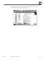
Preface
This programming software user’s manual describes the features that are used to create
ladder logic user programs for the Series 90-70 PLC. These features are available with
Release 7.02 of the Logicmaster 90-70 programming software.
Revisions to This Manual
Changes made to this manual reflect the features of Release 7 of Logicmaster 90-70
software for the Series 90-70 PLC. The Release 7 and later CPU and Logicmaster
software offer new capabilities and expanded functionality which we have documented
in this manual and the Series 90t-70 Programmable Controller Reference Manual
(GFK-0265G). CIMPLICITY Control 2.1 or later is required to take full advantage of
some of the new capabilities of the the Release 7 and later CPUs. Additionally,
corrections and clarifications have been made in this manual where necessary. The
following list describes the major revisions of this manual, as compared to the previous
version (GFK-0263F):
D
New installation instructions for installing under Windowsr 95 or Windows NTr
beginning on page 2-4.
D
If you have a C program but do not have the Toolkit on your PC or if you are putting
the standalone program into more than one folder, Logicmaster now has a way of
accommodating that need. Instructions on how to use the C Standalone Program
Merge feature to bring a C program into your Logicmaster folder. For more
information, refer to the instructions beginning on page 3-76.
D
CPX 772, CPX782, CPX928, and CPX935 support a flash memory option which
allows you to store program logic, configuration data, reference tables, passwords,
and the OEM key to the flash memory device located on the Series 90-70 PLC.
Previously, only the CPU 781 and 782 models could use this option. To learn more
about this, refer to page 9-12.
D
The CPX models of CPUs have embedded serial COM ports giving you the ability to
monitor your program with one of the two new ports while using the other ports for
other communications (usually eliminating the need for an additional
communications module). To learn more about this, refer to page 11-55.
D
The CGR772 and CGR935 CPUs have enhanced Hot Standby features and allows for
configuration of GENIUS dual bus. For more information about these CPUs, refer to
the Series 90t-70 Enhanced Hot Standby CPU Redundancy User‘s Guide (GFK-1527).
*Windows and Windows NT are both registered trademarks of Microsoft, Inc.
GFK-0263G
Logicmaster t 90-70Programming Software User’s Manual – June 1998
iii
The following features are available only with CIMPLICITY
Control:
iv
D
Ethernet Global Data: This feature allows a PLC CPU’s memory to be shared with
the other PLCs and HMI devices on an Ethernet network. It also allows the PLC to
collect data from other PLCs on a periodic basis.
D
Increased Program Size: Using a Release 7.2 or later 90-70 PLC, you can store larger
LD or SFC programs than previously to Series 90-70 PLC CPUs with expansion
memory boards larger than 512 kilobytes.
D
I/O Scan Sets: The I/O Scan Set feature allows the scanning of I/O points to be more
closely scheduled with its use in user logic programs. This feature removes the need
to scan all I/O on every sweep, thus reducing sweep time and increasing
throughput. FIP, IC660/661, and Release 7.2 or later Series 90-70 I/O points can be
assigned to groups called Scan Sets.
D
Selective Synchronous FIP Programs: This feature allows the execution of a user
program to be synchronized with the scanning of a scan set, where at least one input
variable in the set is assigned to a FIP Bus Controller (FBC).
D
VME 3rd Party Interrupts: The Release 7.2 or later Series 90-70 PLC currently allows
interrupts from discrete and analog modules to trigger LD interrupt blocks and
Standalone C programs in the PLC. Release 7.20 of the Series 90-70 PLC extends this
capability to include interrupts from 3rd Party VME modules. Please refer to
GFK-0448E, the User’s Guide to Integration of 3rd Party VME Modules for more details
on VME 3rd Party interrupts.
D
Name Resolution Files: Release 7.20 of the Series 90-70 PLC supports the storing of
Name Resolution Files from Windows programming software to Network Adapters
capable of Name Resolution. Naming Resolution involves resolving a symbolic
name to its necessary address information required for communication. This feature
provides users with a means to use a Symbolic Name to reach the remote
destination.
D
Store/Load/V
erify Genius Block Configuration: PLC Release 7.20 supports the
storing of Genius Device Configuration. Windows programming software Release
2.00 or later is required to configure the devices. The configuration is stored to the
PLC, and is then passed on to the GBC/NBC for eventual storage in the Genius
devices. In addition, load/verify of device configuration will be supported.
Logicmaster t 90-70Programming Software User’s Manual – June 1998
GFK-0263G
Preface
Using This Manual
The information in this book is arranged as chapters that correspond to the main
features of the Logicmaster 90-70 software.
Chapter 1. Introduction: provides an overview of the features available with the
Logicmaster 90-70 programming software. After you read chapter 1, refer to the
chapters that describe the functions you want to use.
Chapter 2. Operation: explains what you need to know to install and start up the
software. It also explains the format of the software screen displays.
Chapter 3. Program Editing: describes program entry and edit features.
Chapter 4. Reference Tables: describes how to display tables of reference values,
change formats in reference tables, force references, and override bit-oriented
references.
Chapter 5. PLC Control and Status: describes how to control and modify the operation
of a connected PLC. These features include how to change the PLC operating state,
display and access PLC privilege levels, display and clear PLC and I/O faults, display
PLC and program memory usage, display configured reference sizes, and modify sweep
parameters.
Chapter 6. Program Librarian: explains how to use the librarian function to reuse
program blocks from other programs without having to re-enter the logic.
Chapter 7. Programmer Setup: explains how to set up the programmer for
communication with the PLC, and how to select the programmer operating mode.
Chapter 8. Program Folders: describes how to create, select, rename, modify, copy, or
delete program folders.
Chapter 9. Program Utilities: describes how to use program utility functions to transfer
programs and tables between the programmer and the PLC, to compare programs and
data in the programmer with programs and data in the PLC, and to clear PLC memory.
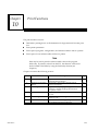
Chapter 10. Print Functions: describes how to use the print functions to enter printer
parameters, create files containing information to be printed, and print copies of
programs, reference tables, and display screens.
Chapter 11. I/O Configuration: describes how to use the configuration software to
configure the I/O modules.
Chapter 12. CPU Configuration: describes how to use the configuration software to set
the operating characteristics of the CPU.
There are eleven appendixes in this manual:
Appendix A. Programming Lesson: provides a sample programming lesson with
simple instructions for creating a program folder, creating a program, entering a variable
declaration, adding ladder logic to the program, printing the program, and exiting the
programmer.
GFK-0263G
Logicmaster
t 90-70Programming Software User’s Manual – June 1998
v
Preface
Appendix B. Configuration Lesson: provides a sample configuration lesson with
simple instructions for creating a program folder and configuring various modules.
Appendix C. Variable Programming Lesson: provides a sample variable programming
lesson.
Appendix D. Programmer Environment Setup: describes how to modify the setup
parameters.
Appendix E. Instruction Mnemonics: lists mnemonics that can be typed to display
program instructions while searching through or editing a program.
Appendix F. Key Functions: lists the special keyboard assignments used for
Logicmaster 90-70 software.
Appendix G. User Command Menu: describes how to maintain a file of MS-DOS
executable commands outside of the Logicmaster software packages.
Appendix H. Data Import: describes how to use ASCII text-based files to quickly
update data zoom blocks in the program editor and data tables in the reference editor.
Appendix I. Files Created with Logicmaster 90-70 Software: describes the files created
by Logicmaster 90-70 software that are associated with the program or folder.
Appendix J. Common User Errors: describes common problems which may occur and
the corrective action to take.
Appendix K. Variable Declaration Table Import/Export Using Comma Separated
Variable (CSV) Format: describes the formatting steps necessary to import a CSV file
into the Variable Declaration Table and/or export from the Variable Declaration Table into
a CSV file.
vi
Logicmaster
t 90-70Programming Software User’s Manual – June 1998
GFK-0263G
Preface
Related Publications
t -70 Programmable Controller Reference Manual (GFK-0265).
Logicmastert 90-70 Important Product Information (GFK-0350).
Series 90t-70 Programmable Controller Installation Manual (GFK-0262).
Series 90t Programmable Coprocessor Module and Support Software User’s Manual
Series 90
(GFK-0255).
t PCM Development Software (PCOP) User’s Manual (GFK-0487).
C Programmer’s Toolkit for Series 90t-70 PLCs User’s Manual (GFK-0646).
Series 90
t
Series 90 Sequential Function Chart Programming Language User’s Manual (GFK-0854).
t Programming Language Reference Manual (GFK-0256).
CIMPLICITYt 90-ADS Alphanumeric Display System User’s Manual (GFK-0499).
CIMPLICITYt 90-ADS Alphanumeric Display System Reference Manual (GFK-0641).
MegaBasic
Alphanumeric Display Coprocessor Module Data Sheet (GFK-0521).
t
Series 90t-70 Genius I/O Analog and Discrete Blocks User’s Manual (GEK-90486-2).
Series 90 -70 Genius I/O System User’s Manual (GEK-90486-1).
Workmasterr II PLC Programming Unit Guide to Operation (GFK-0401).
Series 90t-70 Genius Bus Controller User’s Manual (GFK-0398).
Series 90t-70 FIP Bus Controller User’s Manual (GFK-1038).
Series 90t-70 Remote I/O Scanner User’s Manual (GFK-0579).
Guidelines for the Selection of Third-Party VME Modules (GFK-0448).
Series 90t Ethernet Communications User’s Manual (GFK-0868).
Series 90t MAP 3.0 Communications User’s Manual (GFK-0869).
GFK-0263G
Logicmaster
t 90-70Programming Software User’s Manual – June 1998
vii
Preface
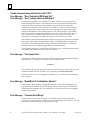
We Welcome Your Comments and Suggestions
At GE Fanuc Automation, we strive to produce quality technical documentation. After
you have used this manual, please take a few moments to complete and return the
Reader ’s Comment Card located on the next page.
David Bruton
Sr. Technical Writer
viii
Logicmaster
t 90-70Programming Software User’s Manual – June 1998
GFK-0263G
Contents
Chapter 1
Chapter 2
Introduction . . . . . . . . . . . . . . . . . . . . . . . . . . . . . . . . . . . . . . . . . . . . . . . .
1-1
Section 1: Product Overview . . . . . . . . . . . . . . . . . . . . . . . . . . . . . . . . . . . . .
1-1
What You Will Need . . . . . . . . . . . . . . . . . . . . . . . . . . . . . . . . . . . . . . . . . . .
MS-DOS Version . . . . . . . . . . . . . . . . . . . . . . . . . . . . . . . . . . . . . . . . . . . . . . .
Help Screens . . . . . . . . . . . . . . . . . . . . . . . . . . . . . . . . . . . . . . . . . . . . . . . . . .
Key Functions . . . . . . . . . . . . . . . . . . . . . . . . . . . . . . . . . . . . . . . . . . . . . . . . .
Before You Begin . . . . . . . . . . . . . . . . . . . . . . . . . . . . . . . . . . . . . . . . . . . . . .
1-2
1-2
1-3
1-3
1-3
Section 2: Configuration Software . . . . . . . . . . . . . . . . . . . . . . . . . . . . . . . .
1-4
CPU Configuration . . . . . . . . . . . . . . . . . . . . . . . . . . . . . . . . . . . . . . . . . . . .
I/OConfiguration . . . . . . . . . . . . . . . . . . . . . . . . . . . . . . . . . . . . . . . . . . . . . .
1-4
1-5
Section 3: Programming Software . . . . . . . . . . . . . . . . . . . . . . . . . . . . . . . . .
1-6
Creating or Editing a Program . . . . . . . . . . . . . . . . . . . . . . . . . . . . . . . . . . .
Displaying Tables of Reference Values . . . . . . . . . . . . . . . . . . . . . . . . . . . .
Starting/Stopping PLC Execution . . . . . . . . . . . . . . . . . . . . . . . . . . . . . . . . .
Fault Display and Clearing . . . . . . . . . . . . . . . . . . . . . . . . . . . . . . . . . . . . . .
PLC Sweep Time Display and Change . . . . . . . . . . . . . . . . . . . . . . . . . . . .
PLC and Program Memory Information . . . . . . . . . . . . . . . . . . . . . . . . . .
Selecting the Programmer Operating Mode . . . . . . . . . . . . . . . . . . . . . . .
System Security . . . . . . . . . . . . . . . . . . . . . . . . . . . . . . . . . . . . . . . . . . . . . . .
Setting up PLC Communications using a WSI Board . . . . . . . . . . . . . . . .
Setting up PLC Serial Communications
Using Standard COM Serial Ports . . . . . . . . . . . . . . . . . . . . . . . . . . . . . .
Program Folders . . . . . . . . . . . . . . . . . . . . . . . . . . . . . . . . . . . . . . . . . . . . . . .
Transferring Programs . . . . . . . . . . . . . . . . . . . . . . . . . . . . . . . . . . . . . . . . . .
Printing Programs and Configuration . . . . . . . . . . . . . . . . . . . . . . . . . . . . .
1-6
1-7
1-7
1-7
1-7
1-8
1-8
1-8
1-9
Operation . . . . . . . . . . . . . . . . . . . . . . . . . . . . . . . . . . . . . . . . . . . . . . . . . .
2-1
Section 1: Hardware Setup (WSI Version)
........................
2-2
Installing the Work Station Interface Board . . . . . . . . . . . . . . . . . . . . . . . .
Grounding . . . . . . . . . . . . . . . . . . . . . . . . . . . . . . . . . . . . . . . . . . . . . . . . . . . .
Cabling . . . . . . . . . . . . . . . . . . . . . . . . . . . . . . . . . . . . . . . . . . . . . . . . . . . . . . .
2-2
2-2
2-2
Section 2: Hardware Setup (Standard Serial Com Version) . . . . . . . . .
Section 3: Software Installation . . . . . . . . . . . . . . . . . . . . . . . . . . . . . . . . . .
2-3
2-4
AUTOEXEC.BAT and CONFIG.SYS Files . . . . . . . . . . . . . . . . . . . . . . . . . .
Running Other Software with the CONFIG.SYS File
For Logicmaster 90-70 Software . . . . . . . . . . . . . . . . . . . . . . . . . . . . . . . .
2-4
Installing Logicmaster Under Windowsr 95
Installing Logicmaster Under Windows NTt
Section 4: Startup/Exit
2-5
. . . . . . . . . . . . . . . . . . . . . . . . . . . . .
2Ć8
. . . . . . . . . . . . . . . . . . . . . . . . . . . .
2Ć8
Installation Instructions . . . . . . . . . . . . . . . . . . . . . . . . . . . . . . . . . . . . . . . . .
Programmer Setup . . . . . . . . . . . . . . . . . . . . . . . . . . . . . . . . . . . . . . . . . . . . .
GFK-0263G
1-9
1-9
1-10
1-10
2-9
2-13
.........................................
2-14
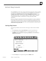
Starting the Programming or Configuration Software . . . . . . . . . . . . . . .
Exiting (Quitting) the Programming or Configuration Software . . . . . .
Programming Software Main Menu . . . . . . . . . . . . . . . . . . . . . . . . . . . . . .
Configuration Software Main Menu . . . . . . . . . . . . . . . . . . . . . . . . . . . . . .
2-15
2-16
2-17
2-19
Table of Contents
ix
Contents
Section 5: Keyboard Functions
..................................
2-22
Keyboards Supported . . . . . . . . . . . . . . . . . . . . . . . . . . . . . . . . . . . . . . . . . .
2-22
Key Functions . . . . . . . . . . . . . . . . . . . . . . . . . . . . . . . . . . . . . . . . . . . . . . . . .
2-22
Keystroke Macros (Teach Mode) . . . . . . . . . . . . . . . . . . . . . . . . . . . . . . . . .
2-22
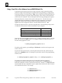
Using a Teach File to Run Software from an MS-DOS Batch File . . . . . .
2-24
Section 6: Screen Format
Chapter 3
.......................................
2-25
Function Key Assignments . . . . . . . . . . . . . . . . . . . . . . . . . . . . . . . . . . . . . .
2-25
Message Line . . . . . . . . . . . . . . . . . . . . . . . . . . . . . . . . . . . . . . . . . . . . . . . . .
2-26
Command Line . . . . . . . . . . . . . . . . . . . . . . . . . . . . . . . . . . . . . . . . . . . . . . . .
2-26
Status Information . . . . . . . . . . . . . . . . . . . . . . . . . . . . . . . . . . . . . . . . . . . . .
2-26
Selecting the Programmer Operating Mode . . . . . . . . . . . . . . . . . . . . . . .
2-28
Program Editing . . . . . . . . . . . . . . . . . . . . . . . . . . . . . . . . . . . . . . . . . . . .
3-1
Section 1: Ladder Logic Program Elements . . . . . . . . . . . . . . . . . . . . . . . .
3-2
Data Zoom . . . . . . . . . . . . . . . . . . . . . . . . . . . . . . . . . . . . . . . . . . . . . . . . . . .
3-17
Section 2: Program Format . . . . . . . . . . . . . . . . . . . . . . . . . . . . . . . . . . . . . . .
3-23
Structure of a Ladder Logic Rung . . . . . . . . . . . . . . . . . . . . . . . . . . . . . . . .
3-25
Section 3: Program Entry . . . . . . . . . . . . . . . . . . . . . . . . . . . . . . . . . . . . . . . .
3-27
Using Mnemonics . . . . . . . . . . . . . . . . . . . . . . . . . . . . . . . . . . . . . . . . . . . . . .
3-27
Inserting Logic Elements . . . . . . . . . . . . . . . . . . . . . . . . . . . . . . . . . . . . . . . .
3-28
Inserting Functions . . . . . . . . . . . . . . . . . . . . . . . . . . . . . . . . . . . . . . . . . . . . .
3-31
Exiting Rung Entry . . . . . . . . . . . . . . . . . . . . . . . . . . . . . . . . . . . . . . . . . . . . .
3-33
Using the Cursor to Select a Reference Table . . . . . . . . . . . . . . . . . . . . . . .
3-33
Section 4: Program Annotation
.................................
3-34
Entering Nicknames and Reference Descriptions . . . . . . . . . . . . . . . . . . .
3-35
Section 5: Variable Declaration Table . . . . . . . . . . . . . . . . . . . . . . . . . . . . . .
3-37
Displaying the Variable Declaration Table . . . . . . . . . . . . . . . . . . . . . . . . .
3-38
Entering Variable Declarations . . . . . . . . . . . . . . . . . . . . . . . . . . . . . . . . . . .
3-40
Editing Variable Declarations . . . . . . . . . . . . . . . . . . . . . . . . . . . . . . . . . . . .
3-41
Copying a Variable Declaration . . . . . . . . . . . . . . . . . . . . . . . . . . . . . . . . . .
3-42
Deleting Variable Declarations . . . . . . . . . . . . . . . . . . . . . . . . . . . . . . . . . . .
3-43
Searching for Variable Declarations . . . . . . . . . . . . . . . . . . . . . . . . . . . . . . .
3-44
Using Goto . . . . . . . . . . . . . . . . . . . . . . . . . . . . . . . . . . . . . . . . . . . . . . . . . . .
3-44
Cut/Pasting Variable Declarations . . . . . . . . . . . . . . . . . . . . . . . . . . . . . . . .
3-44
Automatically Inserting References . . . . . . . . . . . . . . . . . . . . . . . . . . . . . . .
3-44
Viewing the Identifier Table
3-45
....................................
Importing to and Exporting from the Variable Declarations Table
x
....
3-46
Comma Separated Variable (CSV) Format . . . . . . . . . . . . . . . . . . . . . . . . . . . . .
3Ć46
Importing SNF Formatted Files . . . . . . . . . . . . . . . . . . . . . . . . . . . . . . . . . . . . . . .
3Ć46
Exporting SNF (CSV) Formatted Files
3Ć49
................................
Logicmaster 90-70 Programming Software User’s Manual – June 1998
GFK-0263G
Contents
Section 6: Rung Comments . . . . . . . . . . . . . . . . . . . . . . . . . . . . . . . . . . . . . .
Inserting a Rung Comment
....................................
3-51
Adding Text . . . . . . . . . . . . . . . . . . . . . . . . . . . . . . . . . . . . . . . . . . . . . . . . . . .
3-52
Creating Borders . . . . . . . . . . . . . . . . . . . . . . . . . . . . . . . . . . . . . . . . . . . . . .
3-53
Starting a New Page of Comments . . . . . . . . . . . . . . . . . . . . . . . . . . . . . . .
3-54
Printing a Title and Subtitle . . . . . . . . . . . . . . . . . . . . . . . . . . . . . . . . . . . . . .
3-54
Creating Longer Comments . . . . . . . . . . . . . . . . . . . . . . . . . . . . . . . . . . . . .
3-54
Section 7: Changing the Display Mode . . . . . . . . . . . . . . . . . . . . . . . . . . . .
Section 8: Program Blocks, External Blocks, and Interrupts . . . . . . . . . . .
3-55
3-60
Displaying/EditingProgram Blocks . . . . . . . . . . . . . . . . . . . . . . . . . . . . . . .
3-61
Block Declarations . . . . . . . . . . . . . . . . . . . . . . . . . . . . . . . . . . . . . . . . . . . . .
3-61
Adding Block Declarations . . . . . . . . . . . . . . . . . . . . . . . . . . . . . . . . . . . . . .
3-62
Editing Block Declarations . . . . . . . . . . . . . . . . . . . . . . . . . . . . . . . . . . . . . .
3-62
Deleting Block Declarations . . . . . . . . . . . . . . . . . . . . . . . . . . . . . . . . . . . . .
3-62
Searching for Block Declarations . . . . . . . . . . . . . . . . . . . . . . . . . . . . . . . . .
3-63
Using Goto . . . . . . . . . . . . . . . . . . . . . . . . . . . . . . . . . . . . . . . . . . . . . . . . . . .
3-63
Zooming into a Declaration . . . . . . . . . . . . . . . . . . . . . . . . . . . . . . . . . . . . .
3-63
Locking/UnlockingProgram Blocks . . . . . . . . . . . . . . . . . . . . . . . . . . . . . . .
3-63
Interrupts . . . . . . . . . . . . . . . . . . . . . . . . . . . . . . . . . . . . . . . . . . . . . . . . . . . .
3-70
Timed Interrupts . . . . . . . . . . . . . . . . . . . . . . . . . . . . . . . . . . . . . . . . . . . . . .
3-72
Using Interrupts to Invoke External Blocks . . . . . . . . . . . . . . . . . . . . . . . .
3-73
Adding an Interrupt Declaration . . . . . . . . . . . . . . . . . . . . . . . . . . . . . . . . .
3-74
Editing an Interrupt Declaration . . . . . . . . . . . . . . . . . . . . . . . . . . . . . . . . .
3-74
Deleting an Interrupt Declaration . . . . . . . . . . . . . . . . . . . . . . . . . . . . . . . .
3-74
Searching for an Interrupt Declaration . . . . . . . . . . . . . . . . . . . . . . . . . . . .
3-74
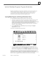
Section 9: Multiple Programs: Program Declarations . . . . . . . . . . . . . . . .
3-75
Inserting Multiple Programs and the Program Declarations Screen
GFK-0263G
3-51
.
3-75
Selecting the Mode and Program Scheduling Options . . . . . . . . . . . . . .
3-78
Specifying Local Data References
...............................
3-82
Section 10: Parameterized Subroutines . . . . . . . . . . . . . . . . . . . . . . . . . . . .
3-83
Block Declarations . . . . . . . . . . . . . . . . . . . . . . . . . . . . . . . . . . . . . . . . . . . . .
3-85
Adding Block Declarations . . . . . . . . . . . . . . . . . . . . . . . . . . . . . . . . . . . . . .
3-87
Editing Subroutine Blocks . . . . . . . . . . . . . . . . . . . . . . . . . . . . . . . . . . . . . . .
3-89
Calling a Parameterized Subroutine in Logic . . . . . . . . . . . . . . . . . . . . . . .
3-91
Inserting/Editing Logic within a Subroutine . . . . . . . . . . . . . . . . . . . . . . .
3-92
Viewing the Variable Declaration Table within a Subroutine . . . . . . . . . .
3-93
Viewing the Parameter Assignment Table . . . . . . . . . . . . . . . . . . . . . . . . .
3-94
Referencing Formal Parameters within a Parameterized
Subroutine Block . . . . . . . . . . . . . . . . . . . . . . . . . . . . . . . . . . . . . . . . . . .
3-95
Changing Formal Parameters . . . . . . . . . . . . . . . . . . . . . . . . . . . . . . . . . . . .
3-97
Search and Replace . . . . . . . . . . . . . . . . . . . . . . . . . . . . . . . . . . . . . . . . . . . .
3-100
Interrupts . . . . . . . . . . . . . . . . . . . . . . . . . . . . . . . . . . . . . . . . . . . . . . . . . . . .
3-101
Table of Contents
xi
Contents
Chapter 4
Section 11: Rung Edit . . . . . . . . . . . . . . . . . . . . . . . . . . . . . . . . . . . . . . . . . . .
3-102
Editing a Rung . . . . . . . . . . . . . . . . . . . . . . . . . . . . . . . . . . . . . . . . . . . . . . . .
Viewing Variable Declarations . . . . . . . . . . . . . . . . . . . . . . . . . . . . . . . . . . .
3-104
3-111
Deleting a Rung . . . . . . . . . . . . . . . . . . . . . . . . . . . . . . . . . . . . . . . . . . . . . . .
3-111
Selecting Rungs . . . . . . . . . . . . . . . . . . . . . . . . . . . . . . . . . . . . . . . . . . . . . . .
Cutting Selected Rungs . . . . . . . . . . . . . . . . . . . . . . . . . . . . . . . . . . . . . . . . .
3-112
3-113
Pasting Previously Cut Rungs . . . . . . . . . . . . . . . . . . . . . . . . . . . . . . . . . . . .
3-114
Writing Selected Rungs to a File . . . . . . . . . . . . . . . . . . . . . . . . . . . . . . . . . .
Including Rungs from a File . . . . . . . . . . . . . . . . . . . . . . . . . . . . . . . . . . . . .
3-115
3-116
Open Space Functions . . . . . . . . . . . . . . . . . . . . . . . . . . . . . . . . . . . . . . . . . .
3-117
Increment/Decrement Reference Address . . . . . . . . . . . . . . . . . . . . . . . . .
Auto-Next Highest Reference . . . . . . . . . . . . . . . . . . . . . . . . . . . . . . . . . . .
3-123
3-125
Section 12: Editor Options . . . . . . . . . . . . . . . . . . . . . . . . . . . . . . . . . . . . . . .
3-127
Coil Checking
...............................................
Automatically Creating Unbound References . . . . . . . . . . . . . . . . . . . . . .
3-127
3-131
Automatically Inserting References . . . . . . . . . . . . . . . . . . . . . . . . . . . . . . .
3-138
Configuring Multiple Languages . . . . . . . . . . . . . . . . . . . . . . . . . . . . . . . . .
3-140
Section 13: Search Function . . . . . . . . . . . . . . . . . . . . . . . . . . . . . . . . . . . . . .
3-142
Using Search and Replace . . . . . . . . . . . . . . . . . . . . . . . . . . . . . . . . . . . . . . .
Implicit Search . . . . . . . . . . . . . . . . . . . . . . . . . . . . . . . . . . . . . . . . . . . . . . . .
3-145
3-147
Search by Reference Type . . . . . . . . . . . . . . . . . . . . . . . . . . . . . . . . . . . . . . .
3-147
Quick Search for a Coil . . . . . . . . . . . . . . . . . . . . . . . . . . . . . . . . . . . . . . . . .
3-147
Section 14: Online Editing/Monitoring . . . . . . . . . . . . . . . . . . . . . . . . . . . .
3-148
Inserting or Editing Rungs (Block Edit) . . . . . . . . . . . . . . . . . . . . . . . . . . . .
3-148
Single Sweep Debug . . . . . . . . . . . . . . . . . . . . . . . . . . . . . . . . . . . . . . . . . . .
Substitutions . . . . . . . . . . . . . . . . . . . . . . . . . . . . . . . . . . . . . . . . . . . . . . . . . .
3-148
3-149
Modifying Instructions . . . . . . . . . . . . . . . . . . . . . . . . . . . . . . . . . . . . . . . . .
3-153
Modifying a Reference Address or Constant . . . . . . . . . . . . . . . . . . . . . . .
Forcing and Overriding Discrete References . . . . . . . . . . . . . . . . . . . . . . .
3-155
3-156
Changing Register Values . . . . . . . . . . . . . . . . . . . . . . . . . . . . . . . . . . . . . . .
3-157
Reference Tables . . . . . . . . . . . . . . . . . . . . . . . . . . . . . . . . . . . . . . . . . . . .
4-1
Section 1: Displaying Reference Tables . . . . . . . . . . . . . . . . . . . . . . . . . . . .
4-2
Displaying a Reference Table . . . . . . . . . . . . . . . . . . . . . . . . . . . . . . . . . . . .
4-3
Using the Cursor to Select a Reference Table . . . . . . . . . . . . . . . . . . . . . . .
Moving the Cursor in a Reference Table . . . . . . . . . . . . . . . . . . . . . . . . . . .
4-3
4-4
Changing the Reference Table (Default) Display Mode (ALT-N) . . . . . .
4-4
Section 2: Changing Reference Table Values
xii
......................
4-6
Changing a Reference Value . . . . . . . . . . . . . . . . . . . . . . . . . . . . . . . . . . . . .
4-6
ASCII String Entry . . . . . . . . . . . . . . . . . . . . . . . . . . . . . . . . . . . . . . . . . . . . .
Forcing a Discrete Reference . . . . . . . . . . . . . . . . . . . . . . . . . . . . . . . . . . . . .
4-7
4-9
Changing the Value of a Word of Discrete References . . . . . . . . . . . . . . .
4-9
Logicmaster 90-70 Programming Software User’s Manual – June 1998
GFK-0263G
Contents
Section 3: Using Overrides
.....................................
4-10
Using Overrides . . . . . . . . . . . . . . . . . . . . . . . . . . . . . . . . . . . . . . . . . . . . . . .
4-11
Removing Overrides . . . . . . . . . . . . . . . . . . . . . . . . . . . . . . . . . . . . . . . . . . .
4-11
Section 4: Changing Display Formats
Chapter 5
............................
4-12
Discrete Reference Tables . . . . . . . . . . . . . . . . . . . . . . . . . . . . . . . . . . . . . . .
4-12
Register Reference Tables . . . . . . . . . . . . . . . . . . . . . . . . . . . . . . . . . . . . . . .
4-13
Display Formats . . . . . . . . . . . . . . . . . . . . . . . . . . . . . . . . . . . . . . . . . . . . . . .
4-13
Changing the Display Format . . . . . . . . . . . . . . . . . . . . . . . . . . . . . . . . . . .
4-17
Timer/CounterFormat . . . . . . . . . . . . . . . . . . . . . . . . . . . . . . . . . . . . . . . . . .
4-19
Returning to Default Values . . . . . . . . . . . . . . . . . . . . . . . . . . . . . . . . . . . . .
4-20
System Reference Table . . . . . . . . . . . . . . . . . . . . . . . . . . . . . . . . . . . . . . . . .
4-21
Section 5: Mixed Reference Tables . . . . . . . . . . . . . . . . . . . . . . . . . . . . . . . .
4-22
Editing the Title . . . . . . . . . . . . . . . . . . . . . . . . . . . . . . . . . . . . . . . . . . . . . . .
4-23
Defining a Mixed Table . . . . . . . . . . . . . . . . . . . . . . . . . . . . . . . . . . . . . . . . .
4-24
Adding %L Data to a Mixed Table . . . . . . . . . . . . . . . . . . . . . . . . . . . . . . . .
4-25
Deleting a Line . . . . . . . . . . . . . . . . . . . . . . . . . . . . . . . . . . . . . . . . . . . . . . . .
4-25
Moving the Cursor . . . . . . . . . . . . . . . . . . . . . . . . . . . . . . . . . . . . . . . . . . . . .
4-26
Exiting from a Mixed Table . . . . . . . . . . . . . . . . . . . . . . . . . . . . . . . . . . . . . .
4-26
Timer/CounterFormat . . . . . . . . . . . . . . . . . . . . . . . . . . . . . . . . . . . . . . . . . .
4-26
PLC Control and Status . . . . . . . . . . . . . . . . . . . . . . . . . . . . . . . . . . . . . .
Run/Stopthe PLC . . . . . . . . . . . . . . . . . . . . . . . . . . . . . . . . . . . . . . . . . . . . . .
5-2
PLC Password Protection
......................................
5-3
..............................................
5-7
PLC Fault Table . . . . . . . . . . . . . . . . . . . . . . . . . . . . . . . . . . . . . . . . . . . . . . . .
5-8
Displaying User-Defined Faults . . . . . . . . . . . . . . . . . . . . . . . . . . . . . . . . . .
5-14
I/OFault Table . . . . . . . . . . . . . . . . . . . . . . . . . . . . . . . . . . . . . . . . . . . . . . . . .
5-16
PLC Memory Used . . . . . . . . . . . . . . . . . . . . . . . . . . . . . . . . . . . . . . . . . . . . .
5-21
Program Block Memory Usage . . . . . . . . . . . . . . . . . . . . . . . . . . . . . . . . . . .
5-22
Configured Reference Sizes . . . . . . . . . . . . . . . . . . . . . . . . . . . . . . . . . . . . .
5-23
PLC CPU Sweep Control . . . . . . . . . . . . . . . . . . . . . . . . . . . . . . . . . . . . . . . .
5-24
Program Memory Usage . . . . . . . . . . . . . . . . . . . . . . . . . . . . . . . . . . . . . . .
5-29
OEM Protection
Chapter 6
Program Librarian . . . . . . . . . . . . . . . . . . . . . . . . . . . . . . . . . . . . . . . . . . .
6-1
Section 1: Listing the Elements in the Library . . . . . . . . . . . . . . . . . . . . . .
6-3
Displaying Information about a Table Entry . . . . . . . . . . . . . . . . . . . . . . .
6-5
Displaying Annotation for an Element . . . . . . . . . . . . . . . . . . . . . . . . . . . .
6-7
Deleting an Element . . . . . . . . . . . . . . . . . . . . . . . . . . . . . . . . . . . . . . . . . . .
6-8
Section 2: Importing an Element from the Library
GFK-0263G
5-1
.................
6-9
Name Conflicts . . . . . . . . . . . . . . . . . . . . . . . . . . . . . . . . . . . . . . . . . . . . . . . .
6-13
Imports Implied by Program Block Calls . . . . . . . . . . . . . . . . . . . . . . . . . .
6-13
Table of Contents
xiii
Contents
Section 3: Redefining Variables . . . . . . . . . . . . . . . . . . . . . . . . . . . . . . . . . .
6-14
Redefining Variables . . . . . . . . . . . . . . . . . . . . . . . . . . . . . . . . . . . . . . . . . . .
Globals Defined in Folder and Library Block . . . . . . . . . . . . . . . . . . . . . . .
Globals Defined in Library Block Only . . . . . . . . . . . . . . . . . . . . . . . . . . . .
Locals Defined in Library Block . . . . . . . . . . . . . . . . . . . . . . . . . . . . . . . . . .
Automatically Filling a Range of To Folder Fields . . . . . . . . . . . . . . . . . . .
Displaying Information about a Table Entry . . . . . . . . . . . . . . . . . . . . . . .
Completing the Operation . . . . . . . . . . . . . . . . . . . . . . . . . . . . . . . . . . . . . .
6-15
6-18
6-22
6-25
6-26
6-28
6-29
Section 4: Exporting an Element to the Library
....................
6-30
Exporting Global Variables . . . . . . . . . . . . . . . . . . . . . . . . . . . . . . . . . . . . . .
6-33
Section 5: Adding an Element to the Library . . . . . . . . . . . . . . . . . . . . . . .
6-34
Completing the Operation . . . . . . . . . . . . . . . . . . . . . . . . . . . . . . . . . . . . . .
6-35
Section 6: Creating/Editing a Reference Offset Template
Chapter 7
xiv
............
6-38
Programmer Setup . . . . . . . . . . . . . . . . . . . . . . . . . . . . . . . . . . . . . . . . . .
7-1
Section 1: Printer Serial Port Setup . . . . . . . . . . . . . . . . . . . . . . . . . . . . . . .
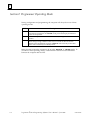
Section 2: Programmer Operating Mode . . . . . . . . . . . . . . . . . . . . . . . . . .
7-3
7-4
Mode Selection . . . . . . . . . . . . . . . . . . . . . . . . . . . . . . . . . . . . . . . . . . . . . . . .
Auto-Verify . . . . . . . . . . . . . . . . . . . . . . . . . . . . . . . . . . . . . . . . . . . . . . . . . . .
7-5
7-5
Section 3: SNP/Parallel Connections . . . . . . . . . . . . . . . . . . . . . . . . . . . . . .
Section 4: Standard Serial COM Port . . . . . . . . . . . . . . . . . . . . . . . . . . . . .
7-6
7-7
Requirements . . . . . . . . . . . . . . . . . . . . . . . . . . . . . . . . . . . . . . . . . . . . . . . . .
Port Requirements . . . . . . . . . . . . . . . . . . . . . . . . . . . . . . . . . . . . . . . . . . . . .
Configuring Memory for the Communications Driver . . . . . . . . . . . . . . .
MS-DOS Memory Areas Defined . . . . . . . . . . . . . . . . . . . . . . . . . . . . . . . . .
Communications Driver Load Order . . . . . . . . . . . . . . . . . . . . . . . . . . . . .
Running Logicmaster 90 Software . . . . . . . . . . . . . . . . . . . . . . . . . . . . . . . .
Setting Up the Computer’s Serial Port . . . . . . . . . . . . . . . . . . . . . . . . . . . .
Setting up the Port . . . . . . . . . . . . . . . . . . . . . . . . . . . . . . . . . . . . . . . . . . . . .
Displaying Port Settings . . . . . . . . . . . . . . . . . . . . . . . . . . . . . . . . . . . . . . . .
Saving the Port Setup . . . . . . . . . . . . . . . . . . . . . . . . . . . . . . . . . . . . . . . . . . .
Displaying File Settings . . . . . . . . . . . . . . . . . . . . . . . . . . . . . . . . . . . . . . . . .
Port Usage Conflicts . . . . . . . . . . . . . . . . . . . . . . . . . . . . . . . . . . . . . . . . . . . .
Memory Manager Specifications . . . . . . . . . . . . . . . . . . . . . . . . . . . . . . . . .
Using High Memory Area on 80386 (Workmaster II)
Or Higher Computers . . . . . . . . . . . . . . . . . . . . . . . . . . . . . . . . . . . . . . . .
Using Upper Memory Block on 80386 (Workmaster II)
Or Higher Computers . . . . . . . . . . . . . . . . . . . . . . . . . . . . . . . . . . . . . . . .
Using Conventional Memory on 80386 (Workmaster II)
Or Higher Computers . . . . . . . . . . . . . . . . . . . . . . . . . . . . . . . . . . . . . . . .
Using Expanded Memory on an 80386 (Workmaster II)
Or Higher Computer . . . . . . . . . . . . . . . . . . . . . . . . . . . . . . . . . . . . . . . . .
Using Video RAM on an 80386 (Workmaster II) Or Higher Computer .
Tested Configurations . . . . . . . . . . . . . . . . . . . . . . . . . . . . . . . . . . . . . . . . . .
7-8
7-8
7-9
7-9
7-10
7-11
7-12
7-13
7-13
7-13
7-13
7-13
7-14
Logicmaster 90-70 Programming Software User’s Manual – June 1998
7-15
7-16
7-17
7-17
7-18
7-19
GFK-0263G
Contents
Section 5: WSI Serial Port
Chapter 8
.......................................
7-20
Setting Up a Port . . . . . . . . . . . . . . . . . . . . . . . . . . . . . . . . . . . . . . . . . . . . . .
Displaying Port Settings . . . . . . . . . . . . . . . . . . . . . . . . . . . . . . . . . . . . . . . .
Saving the Port Setup . . . . . . . . . . . . . . . . . . . . . . . . . . . . . . . . . . . . . . . . . . .
Displaying File Settings . . . . . . . . . . . . . . . . . . . . . . . . . . . . . . . . . . . . . . . . .
7-21
7-21
7-21
7-21
Section 6: View Modes Setup (ALT-N) . . . . . . . . . . . . . . . . . . . . . . . . . . . .
7-22
Changing the View Mode . . . . . . . . . . . . . . . . . . . . . . . . . . . . . . . . . . . . . . .
7-23
Program Folders . . . . . . . . . . . . . . . . . . . . . . . . . . . . . . . . . . . . . . . . . . . .
Drawer . . . . . . . . . . . . . . . . . . . . . . . . . . . . . . . . . . . . . . . . . . . . . . . . . . . . . . .
Program Folder Names . . . . . . . . . . . . . . . . . . . . . . . . . . . . . . . . . . . . . . . . .
TEMP Program Folder . . . . . . . . . . . . . . . . . . . . . . . . . . . . . . . . . . . . . . . . . .
Using Program Folder Functions . . . . . . . . . . . . . . . . . . . . . . . . . . . . . . . . .
Selecting/CreatingProgram Folders . . . . . . . . . . . . . . . . . . . . . . . . . . . . .
Deleting Program Folders . . . . . . . . . . . . . . . . . . . . . . . . . . . . . . . . . . . . . .
Backing Up Program Folders . . . . . . . . . . . . . . . . . . . . . . . . . . . . . . . . . . .
Restoring Program Folders . . . . . . . . . . . . . . . . . . . . . . . . . . . . . . . . . . . . .
Renaming Program Folders . . . . . . . . . . . . . . . . . . . . . . . . . . . . . . . . . . . .
Clearing Program Folders . . . . . . . . . . . . . . . . . . . . . . . . . . . . . . . . . . . . . .
Locking/UnlockingProgram Folders . . . . . . . . . . . . . . . . . . . . . . . . . . . . .
Copying Program Folders . . . . . . . . . . . . . . . . . . . . . . . . . . . . . . . . . . . . . .
Chapter 9
Program Utilities . . . . . . . . . . . . . . . . . . . . . . . . . . . . . . . . . . . . . . . . . . . .
Loading from PLC to Programmer . . . . . . . . . . . . . . . . . . . . . . . . . . . . . .
Storing to the PLC from the Programmer . . . . . . . . . . . . . . . . . . . . . . . . .
Storing a Folder to the PLC from the Configuration Software . . . . . . .
Verifying a Program with PLC . . . . . . . . . . . . . . . . . . . . . . . . . . . . . . . . . .
Clearing PLC Memory . . . . . . . . . . . . . . . . . . . . . . . . . . . . . . . . . . . . . . . .
Using Flash Memory
.........................................
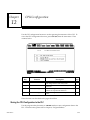
Chapter 10 Print Functions . . . . . . . . . . . . . . . . . . . . . . . . . . . . . . . . . . . . . . . . . . . . .
Print Functions Menu . . . . . . . . . . . . . . . . . . . . . . . . . . . . . . . . . . . . . . . . . .
Section 1: Printer Parameters
8-1
8-2
8-2
8-2
8-4
8-7
8-8
8-10
8-12
8-13
8-14
8-15
9-1
9-3
9-5
9-8
9-9
9-11
9-12
10-1
10-2
...................................
10-3
Changing Setup Printer Parameters . . . . . . . . . . . . . . . . . . . . . . . . . . . . . .
Printer Parameters . . . . . . . . . . . . . . . . . . . . . . . . . . . . . . . . . . . . . . . . . . . . .
10-3
10-4
Section 2: Selecting a Screen Print Device
GFK-0263G
8-1
.........................
10-5
Sending Screen Prints to a Printer . . . . . . . . . . . . . . . . . . . . . . . . . . . . . . . .
Sending Screens to a File . . . . . . . . . . . . . . . . . . . . . . . . . . . . . . . . . . . . . . . .
Saving the Port Designation . . . . . . . . . . . . . . . . . . . . . . . . . . . . . . . . . . . . .
10-5
10-6
10-6
Section 3: Print Program . . . . . . . . . . . . . . . . . . . . . . . . . . . . . . . . . . . . . . . .
10-7
Print Program Parameters . . . . . . . . . . . . . . . . . . . . . . . . . . . . . . . . . . . . . . .
Block Structure . . . . . . . . . . . . . . . . . . . . . . . . . . . . . . . . . . . . . . . . . . . . . . . .
Cross References . . . . . . . . . . . . . . . . . . . . . . . . . . . . . . . . . . . . . . . . . . . . . .
10-8
10-10
10-11
Table of Contents
xv
Contents
Section 4: Print Reference Tables . . . . . . . . . . . . . . . . . . . . . . . . . . . . . . . .
Section 5: Print Configuration . . . . . . . . . . . . . . . . . . . . . . . . . . . . . . . . . . .
10-15
10-18
Accessing the Print Configuration Screen . . . . . . . . . . . . . . . . . . . . . . . . . .
10-19
Pagination Guidelines . . . . . . . . . . . . . . . . . . . . . . . . . . . . . . . . . . . . . . . . . .
10-21
Section 6: Print Function Examples
............................
Chapter 11 I/O Configuration . . . . . . . . . . . . . . . . . . . . . . . . . . . . . . . . . . . . . . . . . . .
11-1
Section 1: Editing I/O Configurations . . . . . . . . . . . . . . . . . . . . . . . . . . . . . .
11-3
Configuration Validation . . . . . . . . . . . . . . . . . . . . . . . . . . . . . . . . . . . . . . . .
11-4
Copying Configuration from Slot to Slot . . . . . . . . . . . . . . . . . . . . . . . . . .
11-5
Changing the Configuration of a Slot . . . . . . . . . . . . . . . . . . . . . . . . . . . . .
11-5
Deleting the Configuration of a Module . . . . . . . . . . . . . . . . . . . . . . . . . . .
11-6
Moving a Module to Another Slot . . . . . . . . . . . . . . . . . . . . . . . . . . . . . . . .
11-6
Saving the Configuration to Disk . . . . . . . . . . . . . . . . . . . . . . . . . . . . . . . . .
11-6
Section 2: Configuring CPU Modules . . . . . . . . . . . . . . . . . . . . . . . . . . . . . .
11-7
Selecting the Sweep Mode . . . . . . . . . . . . . . . . . . . . . . . . . . . . . . . . . . . . . .
11-9
Available CPU Modules
.......................................
11-14
Selecting a Different CPU Module . . . . . . . . . . . . . . . . . . . . . . . . . . . . . . . .
11-14
Configuring Memory Expansion Boards . . . . . . . . . . . . . . . . . . . . . . . . . .
11-15
Configuring CPU Redundancy . . . . . . . . . . . . . . . . . . . . . . . . . . . . . . . . . .
11-17
Section 3: Configuring Rack Type . . . . . . . . . . . . . . . . . . . . . . . . . . . . . . . . .
11-19
Configuring a 9-Slot or 5-Slot Rack
xvi
10-22
..............................
11-19
Configuring a VME Integrator Rack . . . . . . . . . . . . . . . . . . . . . . . . . . . . . .
11-21
Configuring a Series 90-70 Rack from an Integrator Rack . . . . . . . . . . . .
11-23
Configuring a Half-Slot in the Integrator Rack . . . . . . . . . . . . . . . . . . . . .
11-24
Section 4: Configuring a Bus Expansion Module . . . . . . . . . . . . . . . . . . . .
Section 5: Configuring 90-70 I/O Modules . . . . . . . . . . . . . . . . . . . . . . . . . .
11-28
11-29
Configuring a Power Supply Module . . . . . . . . . . . . . . . . . . . . . . . . . . . . .
11-32
Configuring Generic I/O Modules . . . . . . . . . . . . . . . . . . . . . . . . . . . . . . . .
11-34
Section 6: Configuring a Programmable Coprocessor Module . . . . . . . . .
11-40
Configuring a PCM . . . . . . . . . . . . . . . . . . . . . . . . . . . . . . . . . . . . . . . . . . . .
11-41
Selecting the Configuration Mode . . . . . . . . . . . . . . . . . . . . . . . . . . . . . . . .
11-41
CCM ONLY Mode . . . . . . . . . . . . . . . . . . . . . . . . . . . . . . . . . . . . . . . . . . . . .
11-42
PROG PRT Mode . . . . . . . . . . . . . . . . . . . . . . . . . . . . . . . . . . . . . . . . . . . . . .
11-43
BASIC Mode . . . . . . . . . . . . . . . . . . . . . . . . . . . . . . . . . . . . . . . . . . . . . . . . . .
11-44
BAS/CCMMode . . . . . . . . . . . . . . . . . . . . . . . . . . . . . . . . . . . . . . . . . . . . . . .
11-44
PROG/CCMMode . . . . . . . . . . . . . . . . . . . . . . . . . . . . . . . . . . . . . . . . . . . . .
11-44
CCM/PROGMode . . . . . . . . . . . . . . . . . . . . . . . . . . . . . . . . . . . . . . . . . . . . .
11-44
PCM CFG Mode . . . . . . . . . . . . . . . . . . . . . . . . . . . . . . . . . . . . . . . . . . . . . . .
11-45
NONE Mode . . . . . . . . . . . . . . . . . . . . . . . . . . . . . . . . . . . . . . . . . . . . . . . . . .
11-46
Configuring Memory Expansion Boards . . . . . . . . . . . . . . . . . . . . . . . . . .
11-47
Logicmaster 90-70 Programming Software User’s Manual – June 1998
GFK-0263G
Contents
Section 7: Configuring a Communications Module . . . . . . . . . . . . . . . . . .
11-48
Configuring a CMM . . . . . . . . . . . . . . . . . . . . . . . . . . . . . . . . . . . . . . . . . . . .
11-49
Selecting the Configuration Mode . . . . . . . . . . . . . . . . . . . . . . . . . . . . . . . .
11-49
CCM ONLY Mode . . . . . . . . . . . . . . . . . . . . . . . . . . . . . . . . . . . . . . . . . . . . .
11-50
RTU ONLY Mode . . . . . . . . . . . . . . . . . . . . . . . . . . . . . . . . . . . . . . . . . . . . . .
11-51
CCM/RTU Mode . . . . . . . . . . . . . . . . . . . . . . . . . . . . . . . . . . . . . . . . . . . . . . .
11-51
RTU/CCMMode . . . . . . . . . . . . . . . . . . . . . . . . . . . . . . . . . . . . . . . . . . . . . . .
11-51
SNP ONLY Mode . . . . . . . . . . . . . . . . . . . . . . . . . . . . . . . . . . . . . . . . . . . . . .
11-52
SNP/CCMMode . . . . . . . . . . . . . . . . . . . . . . . . . . . . . . . . . . . . . . . . . . . . . . .
11-53
CCM/SNPMode . . . . . . . . . . . . . . . . . . . . . . . . . . . . . . . . . . . . . . . . . . . . . . .
11-53
SNP/RTU Mode . . . . . . . . . . . . . . . . . . . . . . . . . . . . . . . . . . . . . . . . . . . . . . .
11-53
RTU/SNPMode . . . . . . . . . . . . . . . . . . . . . . . . . . . . . . . . . . . . . . . . . . . . . . .
11-53
Section 8: Configuring an ADC Module . . . . . . . . . . . . . . . . . . . . . . . . . . .
11-54
Section 9: Configuring Ports 1 and 2 on a CPX Model CPU . . . . . . . . . . .
11-55
Configuring Ports 1 and 2 . . . . . . . . . . . . . . . . . . . . . . . . . . . . . . . . . . . . . . .
11-55
Section 10: Configuring a Genius Bus Controller . . . . . . . . . . . . . . . . . . . .
11-58
Configuring the Devices on a Genius I/O Bus . . . . . . . . . . . . . . . . . . . . . .
11-61
Configuring Genius I/O Blocks . . . . . . . . . . . . . . . . . . . . . . . . . . . . . . . . . . .
11-62
Configuring Additional Devices (on the Same Bus) . . . . . . . . . . . . . . . . .
11-65
Configuring a Genius High Speed Counter . . . . . . . . . . . . . . . . . . . . . . . .
11-68
Genius Bus Redundancy . . . . . . . . . . . . . . . . . . . . . . . . . . . . . . . . . . . . . . . .
11-70
Changing a Parameter of a Block . . . . . . . . . . . . . . . . . . . . . . . . . . . . . . . . .
11-71
Changing a Parameter of a GBC . . . . . . . . . . . . . . . . . . . . . . . . . . . . . . . . .
11-71
Copying a Block or GBC . . . . . . . . . . . . . . . . . . . . . . . . . . . . . . . . . . . . . . . .
11-71
Deleting a Block . . . . . . . . . . . . . . . . . . . . . . . . . . . . . . . . . . . . . . . . . . . . . . .
11-71
Deleting a GBC . . . . . . . . . . . . . . . . . . . . . . . . . . . . . . . . . . . . . . . . . . . . . . . .
11-72
Configuring Genius Bus Redundancy . . . . . . . . . . . . . . . . . . . . . . . . . . . . .
11-72
Configuring Dual GBC Redundancy . . . . . . . . . . . . . . . . . . . . . . . . . . . . . .
11-77
Configuring Genius Bus Redundancy/Dual GBC Redundancy Together
11-83
Section 11: Configuring a FIP Bus Controller . . . . . . . . . . . . . . . . . . . . . . .
11-89
Section 12: Configuring a Remote I/O Scanner . . . . . . . . . . . . . . . . . . . . .
11-91
Configuring a Series 90-70 PLC for Use with Remote Drops . . . . . . . . . .
11-92
Section 13: Configuring a GEnet MAP Module . . . . . . . . . . . . . . . . . . . . .
11-95
Configuring an MMS or TCP/IP Ethernet Module
.................
11-98
Section 14: Configuring a High Speed Counter . . . . . . . . . . . . . . . . . . . . .
11-101
High Speed Counter Types
GFK-0263G
....................................
11-101
Configuring the High Speed Counter Module . . . . . . . . . . . . . . . . . . . . .
11-102
Table of Contents
xvii
Contents
Section 15: Configuring a Third Party VME Module . . . . . . . . . . . . . . . . .
11-107
Configuring a VME Module . . . . . . . . . . . . . . . . . . . . . . . . . . . . . . . . . . . . .
Selecting the Configuration Mode . . . . . . . . . . . . . . . . . . . . . . . . . . . . . . . .
None Mode . . . . . . . . . . . . . . . . . . . . . . . . . . . . . . . . . . . . . . . . . . . . . . . . . . .
Interrupt Only Mode . . . . . . . . . . . . . . . . . . . . . . . . . . . . . . . . . . . . . . . . . . .
Bus Interface Mode . . . . . . . . . . . . . . . . . . . . . . . . . . . . . . . . . . . . . . . . . . . .
Full Mail Mode . . . . . . . . . . . . . . . . . . . . . . . . . . . . . . . . . . . . . . . . . . . . . . .
Reduced Mail Mode . . . . . . . . . . . . . . . . . . . . . . . . . . . . . . . . . . . . . . . . . . . .
I/O Scan Mode . . . . . . . . . . . . . . . . . . . . . . . . . . . . . . . . . . . . . . . . . . . . . . . .
11-108
11-109
11-110
11-111
11-112
11-114
11-116
11-118
Section 16: Configuration Reference View . . . . . . . . . . . . . . . . . . . . . . . . .
11-120
Displaying the Reference View Table . . . . . . . . . . . . . . . . . . . . . . . . . . . .
Moving the Cursor . . . . . . . . . . . . . . . . . . . . . . . . . . . . . . . . . . . . . . . . . . . . .
Displaying the Rack Screen . . . . . . . . . . . . . . . . . . . . . . . . . . . . . . . . . . . . . .
Displaying the Bus Screen . . . . . . . . . . . . . . . . . . . . . . . . . . . . . . . . . . . . . . .
Overlapping References . . . . . . . . . . . . . . . . . . . . . . . . . . . . . . . . . . . . . . . .
11-120
11-121
11-122
11-123
11-124
Chapter 12 CPU Configuration . . . . . . . . . . . . . . . . . . . . . . . . . . . . . . . . . . . . . . . . . .
Storing the CPU Configuration to the PLC . . . . . . . . . . . . . . . . . . . . . . . .
PLC Date and Time . . . . . . . . . . . . . . . . . . . . . . . . . . . . . . . . . . . . . . . . . . .
SNP ID . . . . . . . . . . . . . . . . . . . . . . . . . . . . . . . . . . . . . . . . . . . . . . . . . . . . . .
PLC Memory Configuration . . . . . . . . . . . . . . . . . . . . . . . . . . . . . . . . . . . .
Fault Categories . . . . . . . . . . . . . . . . . . . . . . . . . . . . . . . . . . . . . . . . . . . . . .
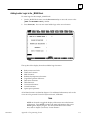
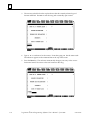
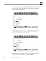
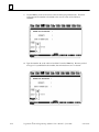
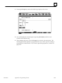
Appendix A Programming Lesson . . . . . . . . . . . . . . . . . . . . . . . . . . . . . . . . . . . . . . .
Help Screens . . . . . . . . . . . . . . . . . . . . . . . . . . . . . . . . . . . . . . . . . . . . . . . . . .
Starting the Lesson . . . . . . . . . . . . . . . . . . . . . . . . . . . . . . . . . . . . . . . . . . . . .
Exiting the Programmer . . . . . . . . . . . . . . . . . . . . . . . . . . . . . . . . . . . . . . . .
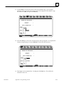
Creating a Program Folder . . . . . . . . . . . . . . . . . . . . . . . . . . . . . . . . . . . . . .
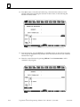
Creating a _MAIN Block . . . . . . . . . . . . . . . . . . . . . . . . . . . . . . . . . . . . . . . .
Entering a Variable Declaration . . . . . . . . . . . . . . . . . . . . . . . . . . . . . . . . . .
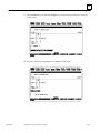
Adding Ladder Logic to the _MAIN Block . . . . . . . . . . . . . . . . . . . . . . . . .
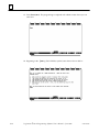
Creating a Program Block . . . . . . . . . . . . . . . . . . . . . . . . . . . . . . . . . . . . . . .
Printing the Program . . . . . . . . . . . . . . . . . . . . . . . . . . . . . . . . . . . . . . . . . . .
Ending the Lesson . . . . . . . . . . . . . . . . . . . . . . . . . . . . . . . . . . . . . . . . . . . . .
Appendix B Configuration Lesson . . . . . . . . . . . . . . . . . . . . . . . . . . . . . . . . . . . . . . . .
Help Screens . . . . . . . . . . . . . . . . . . . . . . . . . . . . . . . . . . . . . . . . . . . . . . . . . .
Starting the Lesson . . . . . . . . . . . . . . . . . . . . . . . . . . . . . . . . . . . . . . . . . . . . .
Creating a Program Folder . . . . . . . . . . . . . . . . . . . . . . . . . . . . . . . . . . . . . .
Displaying the Rack Configuration . . . . . . . . . . . . . . . . . . . . . . . . . . . . . . .
Configuring a CPU Module . . . . . . . . . . . . . . . . . . . . . . . . . . . . . . . . . . . . .
Configuring a 90-70 I/O Module . . . . . . . . . . . . . . . . . . . . . . . . . . . . . . . . .
Configuring a Genius I/O Bus Controller . . . . . . . . . . . . . . . . . . . . . . . . . .
Configuring a Genius I/O Block . . . . . . . . . . . . . . . . . . . . . . . . . . . . . . . . . .
Ending the Lesson . . . . . . . . . . . . . . . . . . . . . . . . . . . . . . . . . . . . . . . . . . . . .
xviii
Logicmaster 90-70 Programming Software User’s Manual – June 1998
12-1
12-1
12-2
12-4
12-5
12-7
A-1
A-1
A-1
A-1
A-2
A-4
A-5
A-7
A-16
A-23
A-24
B-1
B-1
B-1
B-2
B-4
B-5
B-10
B-13
B-15
B-18
GFK-0263G
Contents
Appendix C Variable Programming Lesson . . . . . . . . . . . . . . . . . . . . . . . . . . . . . . . .
C-1
Appendix D Programmer Environment Setup . . . . . . . . . . . . . . . . . . . . . . . . . . . . . .
D-1
Displaying the Setup Screen . . . . . . . . . . . . . . . . . . . . . . . . . . . . . . . . . . . . .
D-1
Selecting Terminal and Printer Options . . . . . . . . . . . . . . . . . . . . . . . . . . .
D-2
Specifying Palette Colors . . . . . . . . . . . . . . . . . . . . . . . . . . . . . . . . . . . . . . . .
D-3
Completing the Disk Drive Setup . . . . . . . . . . . . . . . . . . . . . . . . . . . . . . . .
D-4
PLC Communications Options . . . . . . . . . . . . . . . . . . . . . . . . . . . . . . . . . . .
D-5
Saving the Programmer Environment Setup . . . . . . . . . . . . . . . . . . . . . . .
D-8
Appendix E Instruction Mnemonics . . . . . . . . . . . . . . . . . . . . . . . . . . . . . . . . . . . . . .
E-1
Appendix F Key Functions . . . . . . . . . . . . . . . . . . . . . . . . . . . . . . . . . . . . . . . . . . . . . .
F-1
Appendix G User Command Menu . . . . . . . . . . . . . . . . . . . . . . . . . . . . . . . . . . . . . . .
G-1
Accessing the User Command Menu . . . . . . . . . . . . . . . . . . . . . . . . . . . . .
Appendix H Data Import . . . . . . . . . . . . . . . . . . . . . . . . . . . . . . . . . . . . . . . . . . . . . . . .
Appendix I
Appendix J
GFK-0263G
G-1
H-1
Format and Content of the External File . . . . . . . . . . . . . . . . . . . . . . . . . . .
H-3
Importing Data in the Program Editor . . . . . . . . . . . . . . . . . . . . . . . . . . . .
H-5
Importing Data in the Reference Tables Editor . . . . . . . . . . . . . . . . . . . . .
H-7
Files Created with Logicmaster 90-70 Software . . . . . . . . . . . . . . . . .
I-1
Files in the Program Folder . . . . . . . . . . . . . . . . . . . . . . . . . . . . . . . . . . . . . .
I-2
Files in the Library . . . . . . . . . . . . . . . . . . . . . . . . . . . . . . . . . . . . . . . . . . . . .
I-4
Files in the Logicmaster 90-70 Home Directory . . . . . . . . . . . . . . . . . . . . .
I-5
Cross Reference Data Files . . . . . . . . . . . . . . . . . . . . . . . . . . . . . . . . . . . . . .
I-6
Commom User Errors . . . . . . . . . . . . . . . . . . . . . . . . . . . . . . . . . . . . . . .
J-1
Error Message: “Error Detected in WSI Board” . . . . . . . . . . . . . . . . . . . .
J-1
Trouble Communicating with the Series 90-70 PLC
Error Message: “Error Detected in WSI Board Port”
Error Message: “Error Loading Code into WSI Board” . . . . . . . . . . . .
J-2
Error Message: “File System Error” . . . . . . . . . . . . . . . . . . . . . . . . . . . . . .
J-2
Error Message: “Read/Write PLC Initialization Aborted” . . . . . . . . . . . .
J-2
Error Message: “Constant Out of Range” . . . . . . . . . . . . . . . . . . . . . . . . .
J-2
Cannot Install the Software . . . . . . . . . . . . . . . . . . . . . . . . . . . . . . . . . . . . .
J-3
Error Message: “Comm Driver Not Loaded” . . . . . . . . . . . . . . . . . . . . . .
J-3
Printer Output Is Garbled . . . . . . . . . . . . . . . . . . . . . . . . . . . . . . . . . . . . . . .
J-3
Error Message: “Port/File Access Denied” . . . . . . . . . . . . . . . . . . . . . . . . .
J-3
System Software Error ID: 0000 EX: 0000 . . . . . . . . . . . . . . . . . . . . . . . . . .
J-3
Busy Message Displayed After Load . . . . . . . . . . . . . . . . . . . . . . . . . . . . . .
J-3
Table of Contents
xix
Contents
Appendix K Variable Declaration Table Import/Export Using Comma Separated
Variable (CSV) Format . . . . . . . . . . . . . . . . . . . . . . . . . . . . . . . . . . . . . . .
xx
Logicmaster 90-70 Programming Software User’s Manual – June 1998
K-1
GFK-0263G
Restarts for autonumbers
that do
section level
1 not restart in each
chapter.
figure bi level
1, reset bi level 1
figure
table_big level 1, reset
table_big
level 1
chap_big level
1, reset1
app_big level 1, resetA
figure_ap
level 1
figure_ap level
1, reset
table_ap level 1, reset
table_ap
level
1
figure level 1, reset
table level 1, reset Table 1.
Chapter
1
1
these restarts must be in the header frame of chapter 1.
a:ebx, l 1 resetA
a:obx:l 1, resetA
a:bigbx level 1 resetA
a:ftr level 1 resetA
c:ebx, l 1 reset1
c:obx:l 1, reset1
c:bigbx level 1 reset1
c:ftr level 1 reset1
Reminders for autonumbers that need to be restarted
manually (first instance will always be 4)
let_in level 1: A. B. C.
letter level 1:A.B.C.
num level 1: 1. 2. 3.
num_in level 1: 1. 2. 3.
rom_in level 1: I. II. III.
roman level 1: I. II. III.
steps level 1: 1. 2. 3.
Introduction
section level 1
figure bi level 1
table_big level 1
Section 1: Product Overview
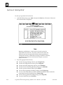
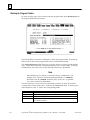
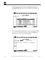
Logicmaster 90-70 programming software is used to configure and program the Series
90-70 programmable controller.
Note
In this manual, the WSI version of Logicmaster 90-70 software refers to
using a Work Station Interface (WSI) Board in the programmer to
provide serial communication between the programmer and the
attached PLC. The standard serial communications version of
Logicmaster 90-70 software refers to using ports COM1 and COM2
instead of the Work Station Interface Board.
Configuration is the process of assigning logical addresses, as well as other
characteristics, to the hardware modules in the system. It may be done either before or
after programming, using the configuration software; however, it is recommended that
configuration be done first.
Programming consists of creating an application program for a PLC.
GFK-0263G
1-1
1
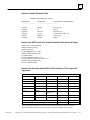
What You Will Need
To run Logicmaster 90-70 software, you will need:
D
A computer with a hard disk:
–
A Workmaster II industrial computer with a 101-key keyboard, or
–
A personal computer with an Intel 80386 or higher processor and a minimum of
2 Megabytes of memory, or
–
A Zenitht Mastersportt SL notebook computer or other laptop computers
with an Intel 80386 or higher processor and a minimum of 2 Megabytes of
memory.
D
D
At least 4 Megabytes of free disk space.
D
The standard serial communications version of Logicmaster 90-70 software requires
either a minimum of 590K of available conventional RAM, or 545K of available
conventional RAM plus an additional 49K of Upper Memory Blocks (UMB), High
Memory Area, or Expanded Memory (EMS) for the communications driver. At least
1024K of Lotus/Intel/Microsoft Expanded Memory (LIM EMS 3.2 or higher) is also
required. (Refer to chapter 7, section 4, “Standard Serial COM Port.”)
The Release 5 WSI version of Logicmaster 90-70 software requires a minimum of
545K of available conventional RAM memory to run and at least 1024K of
Lotus/Intel/MicrosoftExpandedMemory (LIM EMS 3.2 or higher).
Note
Some folders may require additional memory. If additional memory is
required, system software error ID: 0000 EX: 0000 will be displayed.
Check the AUTOEXEC.BAT and CONFIG.SYS files to remove any
device drivers and Terminate and Stay Resident (TSR) programs in
order to free more RAM. Logicmaster 90-70 software does not require
the ANSI.SYS device driver.
MS-DOS Version
To run Logicmaster 90-70 software, MS-DOSr Version 5.0 (or higher) must be installed
on your computer.
Logicmaster 90-70 software provides foreign keyboard support, depending on the
configuration of MS-DOS residing on the host computer. Consult your MS-DOS User’s
Manual for information on configuring for your country.
Note
You can run Logicmaster in a MS-DOS window under Windows 95 or
Windows NT, but you cannot install Logicmaster in a MS-DOS window
under Windows 95 or Windows NT. Refer to Section 3 or Chapter 2 for
details.
t
r
1-2
Zenith and Mastersport are trademarks of Zenith Data Systems Corporation.
MS-DOS is a registered trademark of Microsoft Corporation.
Logicmaster
t 90-70Programming Software User’s Manual – June 1998
GFK-0263G
1
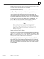
Help Screens
Logicmaster 90-70 software includes detailed Help screens. These Help screens are
loaded onto the hard disk of your programmer during the software installation
procedure and are readily accessible. To access the Help screens, press ALT-H for help,
ALT-I for instruction mnemonic help, or ALT-K for key help.
Key Functions
Appendix E, Key Functions, lists the keyboard functions that are active in the
Logicmaster 90-70 software environment. Appendix E also contains a perforated Help
card which can be removed from this manual. This information may also be displayed
on the programmer screen by pressing ALT-K to access key help.
Before You Begin
You will find Logicmaster 90-70 programming software easy to use and to understand.
When you are ready to begin, turn to chapter 2. It will tell you:
D
D
D
D
How to install the software in your computer.
How to start up the software.
How to use your computer’s keyboard to perform special programming functions.
How to enter data, move the cursor, and read the status information on your screen.
After starting up the software, try the short programming lesson in appendix A and the
configuration lesson in appendix B.
When you are ready to use the programming software to create a program, monitor a
system, or perform any of its other functions, you will find instructions in other chapters
of this book.
GFK-0263G
Chapter 1 Introduction
1-3
1
Section 2: Configuration Software
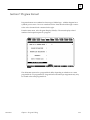
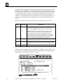
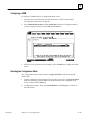
CPU Configuration
Configuration software is used to display and modify the characteristics of the CPU
(such as the time-of-day clock, SNP ID, memory configuration, and fault category).
Chapter 12, “CPU Configuration,” explains how to complete the CPU configuration for
your system. This will set up or change the system features described below.
PLC Time and Date
The PLC maintains the current time and date. These settings can be displayed and
changed using the CPU configuration function.
SNP ID
For multidrop configurations, each CPU connected to the system must have a unique
identification name. The current SNP ID can be displayed and changed using the CPU
configuration function.
PLC Memory Configuration
You can display the current memory allocated to both discrete references and register
references. In addition, you can change the amount of program logic memory used for
analog I/O and register memory.
System Response to Faults
To ensure safe operation of the control system, the PLC must be able to respond
appropriately to certain types of faults. Fatal faults cause the CPU to set fault references
and then go to STOP mode. Diagnostic faults cause the CPU to set fault references, but
the PLC keeps operating. For many faults, the default action (fatal or diagnostic) can be
configured to suit the needs of the application.
1-4
Logicmaster
t 90-70Programming Software User’s Manual – June 1998
GFK-0263G
1
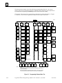
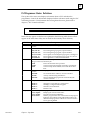
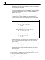
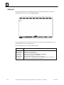
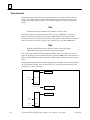
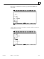
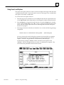
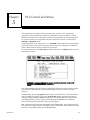
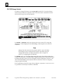
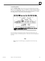
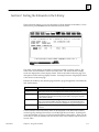
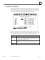
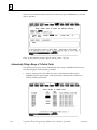
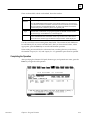
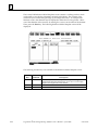
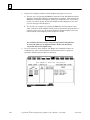
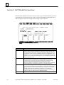
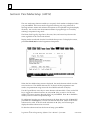
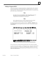
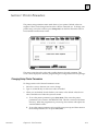
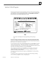
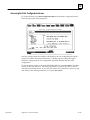
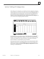
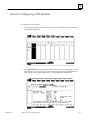
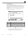
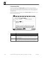
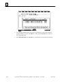
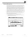
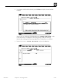
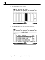
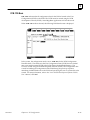
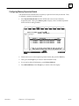
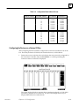
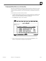
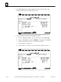
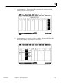
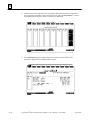
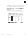
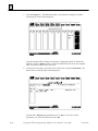
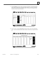
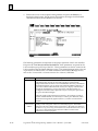
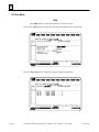
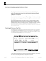
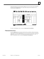
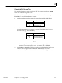
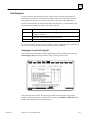
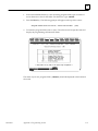
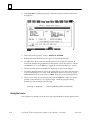
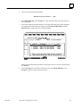
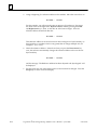
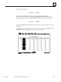
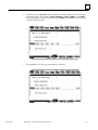
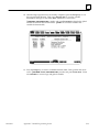
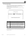
I/O Configuration
The I/O configuration function is used to describe the modules that are present in the
PLC racks, to assign logical addresses, and select options for individual modules. These
logical addresses are independent of physical location or function. Chapter 11, “I/O
Configuration,” explains how to complete the I/O configuration for your system.
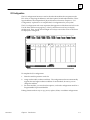
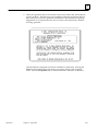
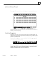
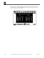
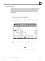
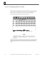
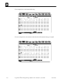
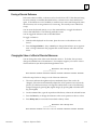
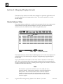
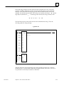
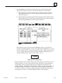
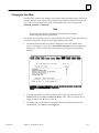
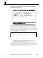
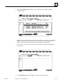
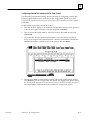
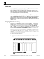
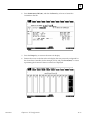
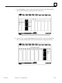
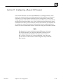
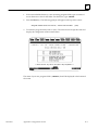
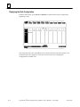
The I/O configuration rack screen represents the appearance of the Series 90-70 I/O rack.
Use the Next and Previous page keys, or the Up and Down cursor keys, to display
another rack. Then, use the Left and Right cursor keys to move the cursor to the slot to
be displayed or configured.
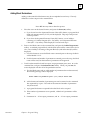
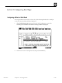
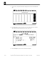
To complete the I/O configuration:
1.
Select the module present in each slot.
2.
Assign each module a reference address. The configuration software automatically
supplies the next highest reference address for each module; however, you can
change this address.
3.
For some modules, you can also select options, such as the configuration mode for a
Programmable Coprocessor Module.
Editing features make it easy to copy, move, replace, delete, or undelete configurations.
GFK-0263G
Chapter 1 Introduction
1-5
1
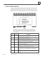
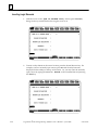
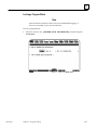
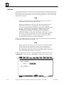
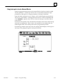
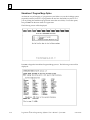
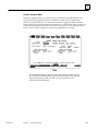
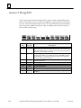
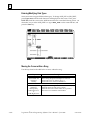
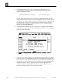
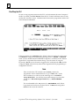
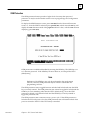
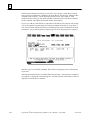
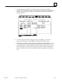
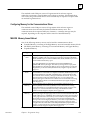
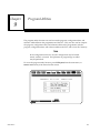
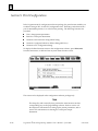
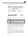
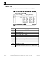
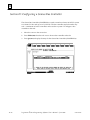
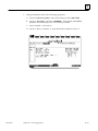
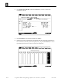
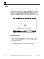
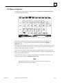
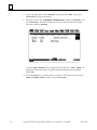
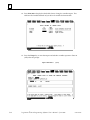
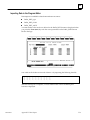
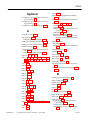
Section 3: Programming Software
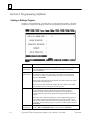
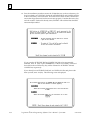
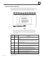
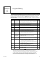
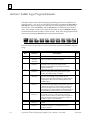
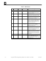
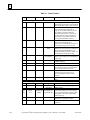
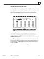
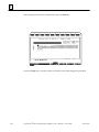
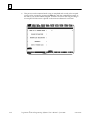
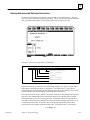
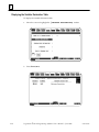
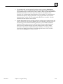
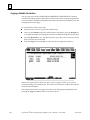
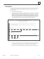
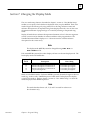
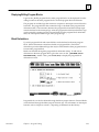
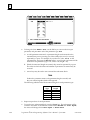
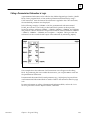
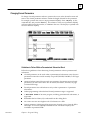
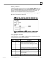
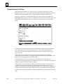
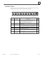
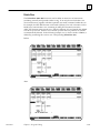
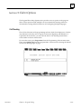
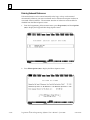
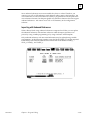
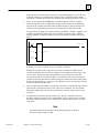
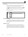
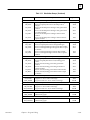
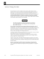
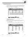
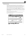
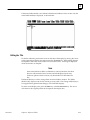
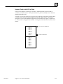
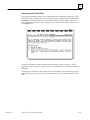
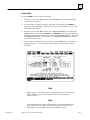
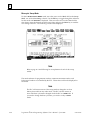
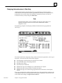
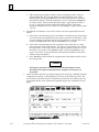
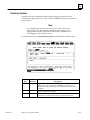
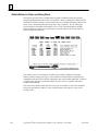
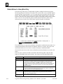
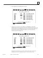
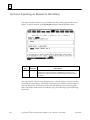
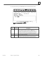
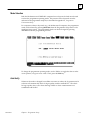
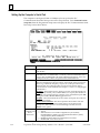
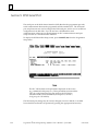
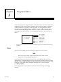
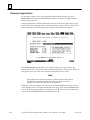
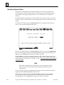
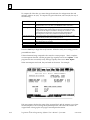
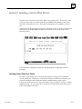
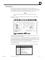
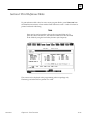
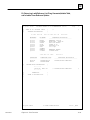
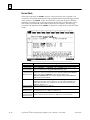
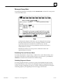
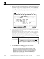
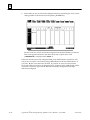
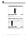
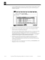
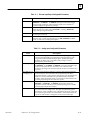
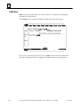
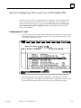
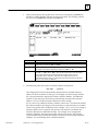
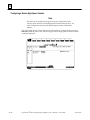
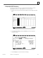
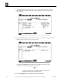
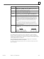
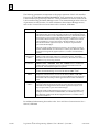
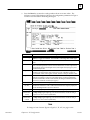
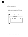
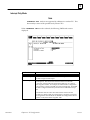
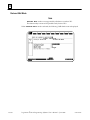
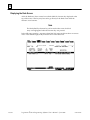
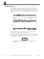
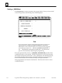
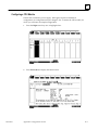
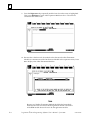
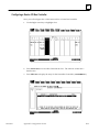
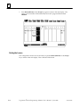
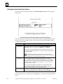
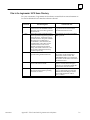
Creating or Editing a Program
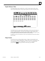
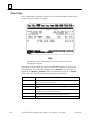
Chapter 3, “Program Editing,” describes how to create and edit programs. The basic
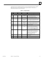
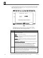
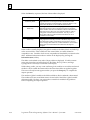
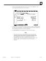
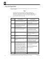
elements of a program are displayed when the programming screen is first selected.
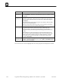
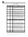
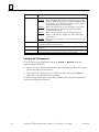
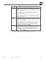
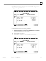
Marker
Variable
Declarations
Program Block
Declarations
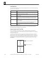
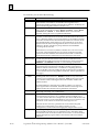
Description
To access the variable declaration table, move the cursor to this marker, and
press Zoom (F10). Nicknames and reference descriptions can then be
entered in the table.
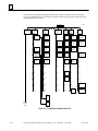
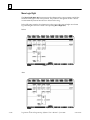
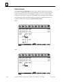
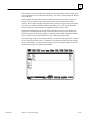
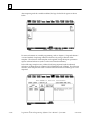
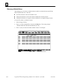
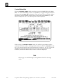
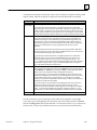
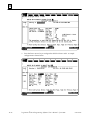
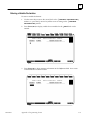
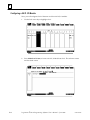
A program can include more than one block of logic. Additional blocks can
be called from other blocks. When that is done, blocks must be declared
before they are called. To declare a block, move the cursor to this marker,
and press Zoom (F10).
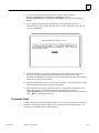
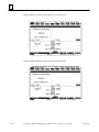
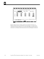
The main block has a block declaration table. This table lists all blocks which
are part of the complete program.
Blocks do not have block declaration tables. However, blocks can be called
from the main block or from any block in the program.
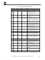
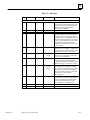
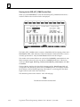
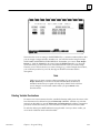
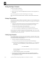
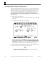
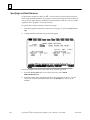
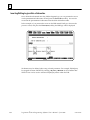
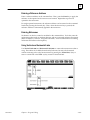
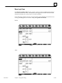
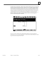
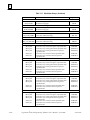
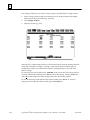
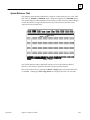
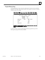
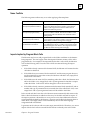
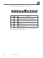
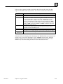
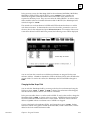
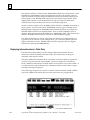
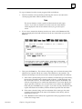
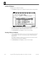
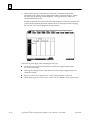
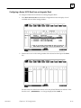
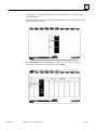
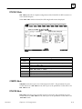
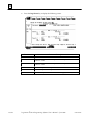
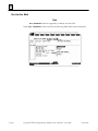
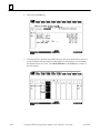
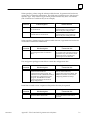
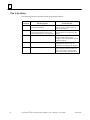
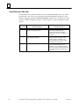
Interrupts
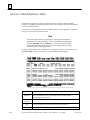
Start/Endof
ProgramLogic
1-6
Logicmaster
The main program block also has a section for interrupts. This lists any
program blocks that will be called as the result of an interrupt from a
hardware module. Interrupt declarations themselves do not declare a
program block; they must first be specified in the program block declaration
section.
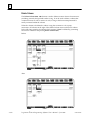
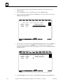
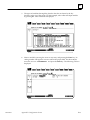
This marker shows where interrupt logic can be included in the program. If
I/O modules capable of generating interrupts are present in the PLC, their
inputs can be used to cause the execution of certain program logic. Their use
is optional. To enter interrupt logic, move the cursor to this marker, and press
Zoom (F10).
All logic is placed between these two markers. To enter logic, place the cursor
on the [END OF PROGRAM LOGIC] marker, and press Insert (F1).
t 90-70Programming Software User’s Manual – June 1998
GFK-0263G
1
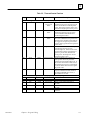
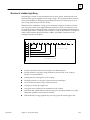
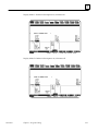
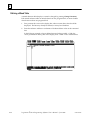
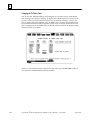
Editing functions include rung insert/edit, select, cut, delete, paste, include, and write. In
addition, search and goto functions allow you to position the cursor on a particular rung
or element. An optional feature of the search function is the replacement of the search
target with a user-specified element and/or reference address.
Chapter 3, section 4, “Program Annotation,” describes how annotation can be added to a
program to make the program easier to read and understand. Three types of annotation
(nicknames, reference descriptions, and rung comments) are supported by Logicmaster
90-70 software.
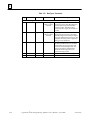
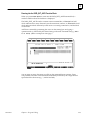
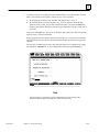
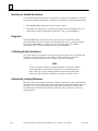
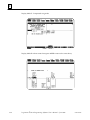
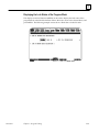
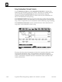
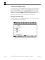
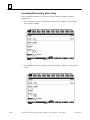
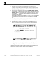
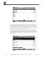
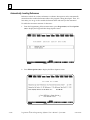
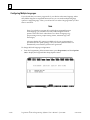
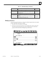
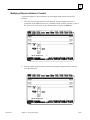
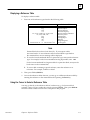
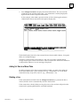
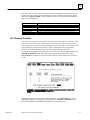
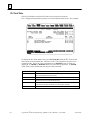
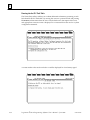
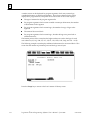
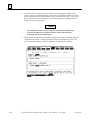
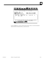
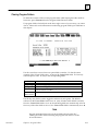
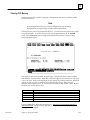
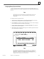
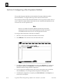
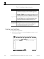
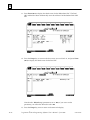
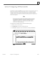
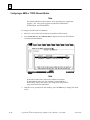
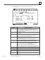
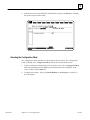
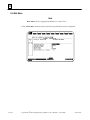
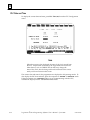
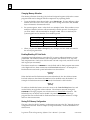
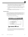
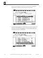
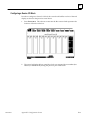
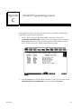
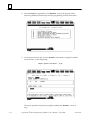
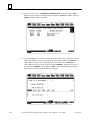
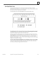
Displaying Tables of Reference Values
Chapter 4, “Reference Tables,” explains how to use the reference tables feature to display
the current values of program references. If the programmer is connected to a PLC and
in ONLINE or MONITOR mode, the values shown in the table are from the PLC. In
OFFLINE mode, they are from the current folder. There are separate tables for each
type of program reference; for example, all discrete inputs (%I), all discrete outputs
(%Q), and all registers (%R). In addition, there are 99 user-defined tables called mixed
reference tables.
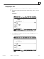
The format of individual items or an entire reference table can easily be changed to units
that are suitable to your application. You can also return a standard reference table to its
default format and fill the table locations with zero.
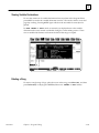
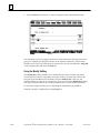
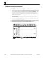
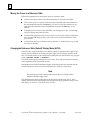
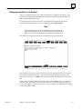
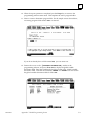
Starting/Stopping PLC Execution
PLC program execution is started or stopped from the Run/Stop PLC screen, or by
pressing ALT-R from any screen. For more information, refer to chapter 5, “PLC Control
and Status.”
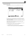
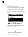
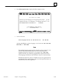
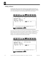
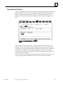
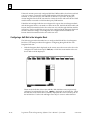
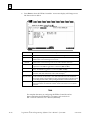
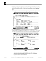
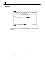
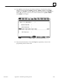
Fault Display and Clearing
When the programmer computer is monitoring an operating PLC system, any faults that
have occurred are displayed in one of two fault tables. PLC faults are listed in the PLC
fault table. Faults from the I/O system are listed in the I/O fault table. All faults are
identified by time, date, and location.
Additional information about each fault can be displayed by positioning the cursor on
the fault in the fault table and pressing the Zoom (F10) softkey.
Faults can be cleared from the fault table displays. For information about the PLC and
I/O fault tables, refer to chapter 5, “PLC Control and Status.”
PLC Sweep Time Display and Change
Chapter 5, “PLC Control and Status,” explains how to use the programming software to:
D
D
D
D
GFK-0263G
Display the current CPU sweep time. This is the amount of time required for one
complete cycle of program execution, I/O scan, communications windows, and other
functions.
See whether or not CONSTANT SWEEP TIME mode is enabled, and read its setting.
Display the currently selected time interval for the watchdog timer. This timer is
used to shut down the CPU if the sweep time is too long.
Display or change the times currently allocated for the programmer window and the
system communications window.
Chapter 1 Introduction
1-7
1
PLC and Program Memory Information
Chapter 5, “PLC Control and Status,” also explains how to display information about:
D
D
D
D
D
PLC memory size.
PLC memory used and available.
User program (RLD) memory used for logic, data, declarations, and annotation.
Memory used for configured program references.
Standalone C program memory size
Selecting the Programmer Operating Mode
Both the programmer and the configuration software operate in three modes:
OFFLINE, MONITOR, and ONLINE. In OFFLINE mode, no data transfer takes place
between the computer and the PLC. Programs and configuration data may
conveniently be developed in OFFLINE mode, with or without the computer
connected to a PLC. In MONITOR mode, if communications have been established
between the computer and the PLC, the computer can read data from the PLC but may
not transfer data to it. With communications established in ONLINE mode, programs
and other data can be transferred between the PLC and the computer.
If you are using a Workmaster or CIMSTAR I industrial computer, you may configure the
Logicmaster 90-70 software to use the keyswitch to select the operating mode. For those
computers without a keyswitch, or if the keyswitch is not enabled, mode selection can be
made by:
D
Pressing the ALT and M keys simultaneously; i.e., press the ALT key and hold it
down, then press the M key. Repeatedly pressing ALT-M switches the operating
mode from OFFLINE to MONITOR to ONLINE and then back to OFFLINE.
D
Going to the Programmer Setup screen (Shift-F7) and selecting an operating
mode. For more information on using the Programmer Setup screen to select the
operating mode, refer to chapter 7, section 2, “Programmer Operating Mode.”
System Security
Security for configuration and program functions consists of:
D
D
D
D
D
A range of four privilege levels for the PLC, which may be protected using passwords.
A software lock that can be applied to individual program folders.
A selectable operating mode.
A software lock that can be applied to individual program blocks.
An OEM key.
Passwords are a configurable feature of the Series 90-70 PLC. Their purpose is to
provide different levels of access privilege for the PLC when the programmer is in
ONLINE mode. Passwords may not be set, or the password access (privilege) level may
not be changed, when the programmer is in OFFLINE mode. The use of passwords is
optional and may be set up using the status functions in the configurator. Passwords
may be used to restrict changing I/O and PLC configuration data, changing programs,
and clearing faults.
Chapter 3, section 8, “Program Blocks, External Blocks, and Interrupts,” describes how
individual program blocks may be locked and unlocked.
Chapter 5, “PLC Control and Status,” describes the programmer’s privilege levels and
explains how to enter passwords. Chapter 5 also describes how passwords are specified.
1-8
Logicmaster
t 90-70Programming Software User’s Manual – June 1998
GFK-0263G
1
Program folders can be protected to prevent accidental changes to program and
configuration information. Each program folder can be either ”locked” or ”unlocked”.
After a folder is locked, its contents cannot be changed or deleted. For more information
on locking program folders, see chapter 8, “Program Folders.”
Setting up PLC Communications using a WSI Board
For the WSI version of Logicmaster 90-70 software, the serial port on the Work Station
Interface (WSI) Board in the programmer provides serial communication between the
programmer and the attached PLC. The COMSET serial port setup function is used to
configure the WSI serial port, and to save or recall those configurations from disk files.
Refer to chapter 7, section 5, “WSI Serial Port,” for instructions on WSI serial port setup.
The parallel port on the WSI Board requires no port setup; however, you must select
PARALLEL as the port connection. Refer also to section 5 of chapter 7 for information
on selecting SNP/parallel connection.
Setting up PLC Serial Communications
Using Standard COM Serial Ports
For the standard serial communications version of Logicmaster 90-70 software, the
COM1 or COM2 serial port may be set up to provide serial communications between the
programmer and the attached PLC. The COMSET serial port setup is used to configure
the COM1 or COM2 serial port, and to save or recall those configurations from disk files.
Refer to chapter 7, section 4, “Standard Serial COM Port,” for instructions on PLC
communications serial port setup.
Program Folders
Each program and the corresponding configuration is assigned to a subdirectory called a
program folder. Both the configuration software and the programming software use a
set of program utility functions to create and maintain program folders. Chapter 8,
“Program Folders,” explains how to use the program folder functions to:
D
D
D
D
D
D
D
D
D
Select another program folder.
Create a new program folder.
Delete an unneeded program folder.
Rename a program folder.
Make a backup copy of the current program folder.
Restore a program folder with its backup copy.
Clear the contents (entire or selective) of the current program folder.
Lock/unlock a program folder.
Copy the contents (entire or selective) of one program folder into the current
program folder.
Application programs and related files can be stored on the same hard disk as the
software. They can also be copied to floppy disks for portability or for independent
storage.
GFK-0263G
Chapter 1 Introduction
1-9
1
Transferring Programs
The program utility functions, described in chapter 9, “Program Utilities,” are used to:
D
D
D
Transfer programs and configuration between the PLC and the programmer.
Clear part or all of the program and/or configuration from PLC memory.
Compare (verify) a program or configuration in the PLC with the current folder to
determine if they are the same.
Printing Programs and Configuration
The programming software includes a complete set of print functions. You can select the
contents and format of the printout. In addition, you can print cross references for the
references used in the program.
You can also print copies of your system configuration by using the print function in the
configuration software. Refer to chapter 10, section 5, “Print Configuration,” for
information about printing configuration screens.
1-10
Logicmaster
t 90-70Programming Software User’s Manual – June 1998
GFK-0263G
Chapter
Operation
2
section level 1
2
This chapter explains what you will need to know to install and start up the Logicmaster
90-70 software. It also explains keyboard use and content of the Logicmaster 90-70
software screens.
GFK-0263G
Section
Title
Description
Page
1
Hardware Setup
(WSI Version)
2-2
2
Hardware Setup
(Standard Serial
CommunicationsVersion)
3
SoftwareInstallation
4
Startup/Exit
5
Keyboard Functions
6
Screen Format
Describes the two Work Station Interface Boards
which are available. Section 1 also provides
information on grounding and cabling.
Describes the serial card which must be installed
in your computer in order to use the standard
serial communications version of Logicmaster
90-70 software.
Explains how to install the Logicmaster 90-70
programming and configuration software on
your computer ’s hard disk.
Describes how to start up Logicmaster 90-70
software.
Describes keyboard functions in the Logicmaster
90-70 software environment.
Shows the format of the display screen and
describes the information that appears.
2-3
2-4
2-14
2-22
2-25
2-1
2
Section 1: Hardware Setup (WSI Version)
Installing the Work Station Interface Board
The Work Station Interface (WSI) Board provides a high-performance serial interface
between a Series 90-70 PLC and the programmer for the WSI version of Logicmaster
90-70 software.
There are two Work Station Interface Boards available; one is for an AT-type computer,
and the other is for a PS/2-type computer. The WSI Board is included as part of a
package with Logicmaster 90-70 programming software. If you have a Workmaster II
computer, the WSI board was installed at the factory. For installation instructions on
other programming devices, consult the computer manufacturer’s instructions for
option boards.
Grounding
Be sure the computer has a ground connection in common with the CPU rack. This is
usually done by connecting the programmer computer to the same power source (with
the same ground reference point) as the rack.
Warning
If the programmer is not connected as described above, damage to the
Work Station Interface Board can occur. Erratic control operation may
also result. If the programmer is online to an operating system,
possible erratic operation may cause conditions which are hazardous
to personnel and equipment.
Cabling
The communications cable that connects the computer to the PLC is a shielded twisted
pair cable with a 37-pin D connector on each end. The maximum length for this cable is
50 feet. After installing the Work Station Interface Board in your computer, connect the
computer to the PLC by first attaching the cable to the Work Station Interface Board and
then to either the SNP port on the CPU module or the parallel port on the Bus
Transmitter Module (BTM).
2-2
Logicmaster
t 90-70Programming Software User’s Manual – June 1998
GFK-0263G
2
Section 2: Hardware Setup (Standard Serial Com Version)
If you have the Logicmaster 90-70 version of software which communicates with the
PLC using the standard serial communication ports, a serial board with COM1, COM2,
COM3, or COM4 must be installed in the computer in order to communicate with the
PLC. Refer to GFK-0262, Series 90-70 Programmable Controller Installation Manual, for
instructions on establishing a serial connection between the Series 90-70 PLC serial port
and the serial port on the programming computer, without having a Work Station
Interface Board installed in the computer.
GFK-0263G
Chapter 2 Operation
2-3
2
Section 3: Software Installation
To use Logicmaster 90-70 software, it must be installed on the programmer computer’s
hard disk or network disk. MS-DOS Version 3.1 or later must already exist on the hard
disk or network disk.
The Logicmaster 90-70 installation procedure creates three subdirectories on the hard
disk:
Software Version
Subdirectories Created
WSI
\LM90
\LM90\P70
\LM90\C70
Standardserial communications
\LM90
\LM90\P70S
\LM90\C70S
Note
Refer to the IPI accompanying the specific release of Logicmaster for
updated instructions on installation of the Logicmaster software. The
information presented in this chapter is not intended to reflect
differences in specific releases of the Logicmaster software.
Also, please note that you cannot install most versions of Logicmaster
in a MS-DOS box under Windows 95 or Windows NT. You have to
restart in DOS mode and then install. Refer to the IPI for specific
instructions.
There is a new version of Logicmaster (IC641SWP716) that was
specifically designed as a DOS application that installs and works
under Windows NT and Windows 95. This new version provides SNP
or TCP/IP Ethernet communications to Series 90-70 PLCs and uses
standard TCP/IP Windows drivers to provide maximum compatibility
in a network environment. As a program designed for Windows NT
and Windows 95, it consumes less of the system resources, easily
handling the multitasking attributes of the Windows NT or Windows
95 operating system. For more information about this new product,
call 1-800-GEFanuc.
AUTOEXEC.BAT and CONFIG.SYS Files
Before starting to install Logicmaster 90-70 software, check the content of your hard disk
root directory to see whether the CONFIG.SYS and AUTOEXEC.BAT files are present.
Operation of Logicmaster 90-70 software requires these files to be present. If they are
not, they will be installed automatically during the installation. If your hard disk already
has these two files, you may be asked during installation whether the INSTALL process
2-4
Logicmaster
t 90-70Programming Software User’s Manual – June 1998
GFK-0263G
2
should modify them. If you prefer, you can edit your existing files for use with
Logicmaster 90-70 software.
The CONFIG.SYS (System Configuration) file is a short, readable file that describes the
configuration of MS-DOS. Different software packages may use different system
configurations. For all Logicmaster 90-70 applications, the file must contain at least these
two lines:
Buffers = 15
Files
= 20
Note
If MS-DOS 5.0 is used and is loaded high, buffers may be set higher
(e.g., buffers = 60). This will help Logicmaster 90-70 software
performance during program searches, program loads, program stores,
and other disk operations.
If you want to check the content of an existing CONFIG.SYS file, you can use the TYPE
command.
Caution
If an existing CONFIG.SYS file is modified, you must reboot your
machine before running Logicmaster 90-70 software.
The AUTOEXEC.BAT file must have (drive ID):\LM90 added to the existing path.
(drive ID) is the letter which corresponds to the hard disk drive where Logicmaster
90-70 software is installed.
If you need to run Version 5.0 or later of Logicmaster 90-70 software from a disk that
does not contain the software, add this to your AUTOEXEC.BAT file:
SET $PLCROOT=(drive ID):\LM90
Running Other Software with the CONFIG.SYS File
For Logicmaster 90-70 Software
Other types of software may require different entries in the CONFIG.SYS file. It is not
always possible to combine the requirements for multiple software packages in one
CONFIG.SYS file. In that case, you must maintain multiple versions of the CONFIG.SYS
file with different file names. Your MS-DOS manual contains more information about
the CONFIG.SYS file.
Caution
If the CONFIG.SYS or AUTOEXEC.BAT file loads many RAM
resident utilities, Logicmaster 90-70 software may not run. These
utilities should be kept at a minimum when running Logicmaster 90-70
software.
GFK-0263G
Chapter 2 Operation
2-5
2
If you have loaded device drivers for special devices or a local area network, which
terminate and stay resident, these programs may need to be removed before installing
and running the Logicmaster 90-70 software. The MS-DOS CHKDSK or MEM
command may be used to determine available memory (bytes free).
Logicmaster 90-70 software does not require the ANSI.SYS device driver; it may be
removed in order to obtain more memory.
If you want to check the content of an existing CONFIG.SYS file, you can use the TYPE
command. (Recommended buffer size is 40; minimum is 15.)
D
The WSI version of Logicmaster 90-70 software requires a minimum of 545 KB
(558,080 bytes) of available MS-DOS application memory in order to run.
The Standard Serial COM Port version requires either a minimum of 590 KB (604,160
bytes) of available DOS application memory, or 520 KB (532,480 bytes) of available
DOS application memory and 42 KB of available High Memory Area, Upper Memory
Block or Expanded Memory for the COM port driver (see page NO TAG and
following for details about the Standard Serial COM Port version and memory
management).
Both versions require a minimum 1024 KBofLotus/Intel/MicrosoftExpanded
Memory (LIM EMS 3.2 or higher) for optimum performance. If additional DOS
application memory (also called “low memory” or “conventional memory”) is
needed, system software error ID: 0000 EX: 0000 will occur. Remove any unneeded
TSR (Terminate and Stay Resident) programs and any unnecessary device drivers
from the AUTOEXEC.BAT and CONFIG.SYS files to make more memory available.
The following configurations will assist you in setting up your computer system to
run Logicmaster 90-70 software optimally on 386/486 computers with a minimum of
2 MB RAM.
Logicmaster 90-70 Software
(Standard MS-DOS Version 5.0)
CONFIG.SYS
2-6
Logicmaster
Configuration
DEVICE=C:\DOS\HIMEM.SYS
DOS=HIGH ,UMB
DEVICE=C:\DOS\EMM386.EXE1024 RAM X=CE00–CFFF
FILES=20
BUFFERS=40
t 90-70Programming Software User’s Manual – June 1998
GFK-0263G
2
Note
The above EMM386.EXE switch “X=CE00–CFFF ” is used to reserve this
area of memory for the Series 90-70 WSI card. If the computer does not
have a WSI card, the “X= CE00– CFFF” is not required; however, the
“EMM386.EXE 1024 RAM” specification enhances performance and may
be necessary if you have over 537 MB of free hard disk space (see next
paragraph below). If you have less than 537 MB of free hard disk space,
the special precautions discussed below are unnecessary.
If you have over 537 MB of free hard disk space and you have the
statementDEVICE=C:\DOS\EMM386.EXENOEMS in your
CONFIG.SYS, you will receive the following error: (00032) An
unknown error occurred during install initialization.
To prevent this error. from occurring, you must specify Expanded
Memory in your CONFIG.SYS, e.g., DEVICE=C:\DOS\EMM386.EXE
1024 RAM. If you are using a commercial memory manager, such as
QEMM or 386MAX , this precaution may not be necessary. (See IPI
GFK-0350 which comes with this Logicmaster release for examples of
tested configurations using QEMM and 386MAX .)
t
t
t
t
In addition, some folders may require additional memory. If additional
memory is required, system software error ID: 0000 EX: 0000 will be
displayed. Check the AUTOEXEC.BAT and CONFIG.SYS files to
remove any device drivers and Terminate and Stay Resident (TSR)
programs in order to free more RAM. Logicmaster 90-70 software does
not require the ANSI.SYS device driver.
The AUTOEXEC.BAT file must have (drive ID):\LM90 added to the existing path.
(drive ID) is the letter which corresponds to the hard disk drive where Logicmaster
90-70 software is installed.
If you need to run Version 4.01 or later of Logicmaster 90-70 software from a disk that
does not contain the software, add this to your AUTOEXEC.BAT file:
SET $PLCROOT=(drive ID):\LM90
t 386MAX is a trademark of Qualitas, Inc.
t QEMM-386 and QRAM are trademarks of Quarterdeck Office Systems.
GFK-0263G
Chapter 2 Operation
2-7
2
Installing Logicmaster Under Windowsr 95
You can run Logicmaster under Windows 95, but you cannot install it without
rebooting into DOS mode. Although Windows 95 supports most standard DOS
programs, the Logicmaster distribution diskettes contain a copy protection track
that cannot be read using normal DOS file services. You must shut down the
Windows 95 operating system and restart the computer in DOS mode before
running the Logicmaster 90 Install program for both Logicmaster and SFC.
Follow these steps for a successful installation.
D
D
Click the Windows 95 Start button and select Shut Down.
D
At the DOS prompt, insert the first Logicmaster distribution diskette and type A: (or
B:), press Enter, then type INSTALL.
D
D
D
Proceed with the standard installation.
From the Shut Down dialog box, select the “Restart the computer in MS-DOS mode”
option and press Enter.
Configure your CONFIG.SYS and AUTOEXEC.BAT files as discussed previously.
Restart your computer.
Installing Logicmaster Under Windows NTt
You can run Logicmaster under Windows NT, but you cannot install it without
going into DOS mode. To do so, restart your computer and select the option
that takes you into standard DOS mode. Then follow the steps shown above for
Windows 95 beginning with the third step.
If you do not have MS-DOS on your NT system, you can temporarily reboot from a
floppy drive with an MS-DOS system disk if your NT system uses FAT-based file system.
Note
Logicmaster 90-70 TCP/IP Ethernet for DOS cannot be run from a DOS
window under Windowsr, Windows 95, or Windows NT. For the
other versions of Logicmaster, refer also to the IPI accompanying
the software disks for additional information about installing
Logicmaster.
There is a new version of Logicmaster (IC641SWP716) that was
specifically designed as a DOS application that installs and works under
Windows NT and Windows 95. This new version provides SNP or
TCP/IPEthernet communications to Series 90-70 PLCs and uses
standard TCP/IP Windows drivers to provide maximum compatibility in
a network environment. As a program designed for Windows NT and
Windows 95, it consumes less of the system resources, easily handling
the multitasking attributes of the Windows NT or Windows 95
operating system. For more information about this new product, call
1-800-GEFanuc.
2-8
Logicmaster
t 90-70Programming Software User’s Manual – June 1998
GFK-0263G
2
Installation Instructions
GFK-0263G
1.
Boot up the computer using MS-DOS.
2.
Be sure the CONFIG.SYS file has files set to at least 20, i.e., FILES=20.
3.
Remove the write-protect tab from the disk.
4.
Insert the Logicmaster 90-70 software disk into the computer’s disk drive.
5.
At the MS-DOS prompt, enter the designation of the disk drive followed by a colon.
For example, if the disk is in drive A, type: A: and press the Enter key.
6.
Begin the installation procedure by typing: INSTALL and pressing the Enter key.
The following screen is displayed.
Chapter 2 Operation
2-9
2
7.
Specify the hard disk drive and press the Enter key, or just press the Enter key if the
default is correct. The following screen is displayed if this is the first installation of
this disk.
Note
The Serial Number field must contain the serial number from your
registration card or the back of the distribution disks.
8.
Use the cursor keys to move between fields. Each field is validated as you move off
the field. You must fill in all of the fields and press the Enter key in order for the
installation process to continue. If any fields are empty or invalid when the Enter
key is pressed, the first invalid field is highlighted and an error message is displayed.
The system will prompt you to confirm that the registration information is correct as
displayed.
If the registration data is not correct, press: N (No) and correct the registration
information. When the registration data is correct, press: Y (Yes). The data is then
encoded and written onto the master distribution disk. This screen is displayed until
the registration data is successfully written to the master disk, or until the
installation program is aborted by pressing the Escape key. You may print this
screen by pressing the Print Screen key.
2-10
Logicmaster
t 90-70Programming Software User’s Manual – June 1998
GFK-0263G
2
9.
When the registration data is successfully written to the master disk, the installation
process can begin. The following screen is displayed after the registration data has
been entered, or on future Logicmaster installations of the same software package.
(Registration is not required once the data is written to the master disk.) Read the
licensing agreement.
This information is displayed each time an installation is performed. Pressing the
Enter key after reading this screen means you agree to comply with the stated
terms. Press the Escape (ESC) key to terminate INSTALL and return to MS-DOS.
GFK-0263G
Chapter 2 Operation
2-11
2
10. First, the installation procedure creates the \LM90 directory in the root directory, if it
does not already exist. INSTALL checks the AUTOEXEC.BAT and CONFIG.SYS files
in the root directory of the hard disk. These files must contain certain commands to
ensure that Logicmaster 90-70 software executes properly. If neither file exists, they
are both created. If either file already exists, INSTALL will ask if the files should be
automatically modified.
If you want the AUTOEXEC.BAT and CONFIG.SYS files to be automatically
modified, enter Y (Yes) or press the Enter key. If there were already versions of
those files in the root directory, they will be renamed to AUTOEXEC.L90 and
CONFIG.L90, respectively.
If you already have AUTOEXEC.BAT and/or CONFIG.SYS files and plan to edit
them yourself, enter N (No). The following screen is displayed:
2-12
Logicmaster
t 90-70Programming Software User’s Manual – June 1998
GFK-0263G
2
11. If you are using a Workmaster industrial computer, remove the lines
device=c:\gexmem2.sys and device=c:\gexdisk.sys. The line
device=c:\gexdisk.sys. The line device=c:\gexmem.sys may remain for Expanded
Memory.
12. If you change your mind and want INSTALL to automatically update the
AUTOEXEC.BAT and CONFIG.SYS files, enter Y (Yes). Otherwise, enter N (No)
or press the Enter key.
13. INSTALL attempts to create three subdirectories under the root directory on the
hard disk, and transfers the appropriate files to those subdirectories. If the
subdirectories already exist, any files in them are deleted and the new files installed.
If folders exist, they are not deleted.
14. INSTALL will then prompt you to insert any other disks. After all the files have been
transferred, the final installation screen is displayed.
15. The computer must now be rebooted in order to complete the installation process.
After removing the last disk used during the installation process, press
CTRL-ALT-Delete to reboot the computer. When the MS-DOS prompt is displayed,
enter LM90 to start up the software.
Programmer Setup
A default setup file is created during installation. Only in special circumstances will this
file need to be changed. Refer to appendix D, “Programmer Environment Setup,” for
instructions on modifying the setup parameters.
GFK-0263G
Chapter 2 Operation
2-13
2
Section 4: Startup/Exit
To start up Logicmaster 90-70 software:
1.
At the MS-DOS prompt, type LM90 and press the Enter key. The menu of Series 90
PLCs and functions is displayed.
Note
Beginning with Release 4, a teach file can be used to enter the
Logicmaster 90-70 software. This entry teach file will contain the
keystrokes previously taught while entering the programming or
configurator software. Information on using a teach file to enter the
Logicmaster 90-70 software can be found in chapter 2, section 5,
Keyboard Functions.
2.
Press the appropriate function key:
D
D
D
D
D
D
D
D
D
2-14
To select the programming software, press Program (F1).
To select the configuration software, press Config (F2).
To select the PCM configuration software, press PCM (F3).
To select the Axis Positioning Module package, press APM (F4).
To select operator interface utilities, press OI (F5).
To access the Logicmaster 90 utilities package, press Utilities (F7).
To access a file of MS-DOS executable commands (COMENU.PRD) outside the
Logicmaster 90 software package, press Comenu (F8).
To access the Logicmaster 90 setup package, press Setup (F9).
To return to MS-DOS, press Exit (F10).
Logicmaster
t 90-70Programming Software User’s Manual – June 1998
GFK-0263G
2
3.
If only one version of Logicmaster 90-70 software (either WSI or standard serial
communications) is installed, it will be run automatically. If both versions are
installed, the Logicmaster 90 Setup Package (F9) can be used to select the version to
run. Refer to appendix D, “Programmer Environment Setup,” for instructions on
modifying the programmer environment setup.
Starting the Programming or Configuration Software
To load the programming software, select Program (F1) from the menu of Series 90 PLCs
and functions, shown on the previous page. To load the configuration software, select
Config (F2). After selecting Program (F1) or Config (F2), the following screen appears:
When the Logicmaster 90-70 software powers up, it attempts to automatically select a
program folder.
GFK-0263G
D
If there is a program folder beneath the drawer last selected, whose name matches
the program name in the attached PLC, that folder is selected.
D
If the current directory is a program folder and its name matches the program name
in the attached PLC, that folder is selected.
D
If there is a program folder beneath the current directory, whose name matches the
program name in the attached PLC, that folder is selected.
D
D
If the current directory is a program folder, it is selected.
Other wise, the initial select screen is displayed with the name of the last folder
selected in the Folder field.
Chapter 2 Operation
2-15
2
Note
At serial baud rates of 1200 or less, the folder cannot be automatically
selected during startup. Once in the programming software, however,
you may use the auto function to automatically select a folder. (Refer to
the information on “Automatic Folder Selection” in chapter 8, “Program
Folders.”)
Enter a name of up to seven characters for the program folder. (The name is also used
for the program.) After entering a name, press the Enter key. If you need more
information about program folders, refer to chapter 8, “Program Folders”.
Exiting (Quitting) the Programming or Configuration Software
To exit the software at any time, press CTRL-Break and confirm the prompt, or
repeatedly press the Escape key at each prompt. You should always exit the software
before turning the computer off; otherwise, some changes may be lost.
If you respond to the exit prompt (“Exit Logicmaster 90 Package? (Y/N)”) by entering a
1 instead of a Y (Yes) or N (No), a bookmark feature saves the current context. The
next time you run the software, you will return to the same general location when you
re-enter the software.
2-16
Logicmaster
t 90-70Programming Software User’s Manual – June 1998
GFK-0263G
2
Programming Software Main Menu
If you select Program (F1) from the menu of Series 90 PLCs and functions, the
Programming Software main menu shown below is displayed. This menu is used to
access the primary functions of Logicmaster 90-70 programming software.
Note
For the WSI version of Logicmaster 90-70 software, WSI is displayed
after the version number in the screen shown above. For the standard
serial communications version of software, COM is displayed after the
version number.
GFK-0263G
Function
Key
Function
Description
F1
Program
F2
Tables
F3
Status
F6
Librarian
F7
Setup
F8
Folder
F9
Utility
F10
Print
Create or edit a program or monitor program logic. Chapter 3
describes the program display and explains how to create or edit a
program.
Display and change reference data. To select a particular reference
table, enter the reference type on the command line before pressing
F2. Chapter 4 describes monitoring data and explains how to change
tables and variable data.
Select the status functions. These functions include displays of I/O
faults and PLC faults. The memory configuration and the current PLC
access level can also be viewed. Chapter 5 describes these functions.
List the contents of the library, import a block from the library, export a
block to the library, add an element to the library, or create/edit reference offset templates. Chapter 6 describes these features.
Display and change serial port setup and other programmer
configuration. Chapter 7 explains how to use these functions.
Create, select, clear, rename, delete, lock, or back up a program folder.
Chapter 8 explains how to use the folder functions.
Load, store, or verify a program, or clear PLC memory. Chapter 9
explains how to use the utility functions.
Print a program folder. Chapter 10 describes the print functions.
Chapter 2 Operation
2-17
2
The function keys remain active after selecting a programming function. You can go
directly from one programming function to another without returning to the main menu
by simultaneously pressing the shift key and the desired function softkey.
The bottom of the main menu screen displays three lines of status information. Chapter
2, section 6, Screen Format, explains the content of the screen’s status area.
a44856
MAIN MENU
F1
F2
F3
Program
Display
and Edit
Reference
Tables
PLC
Control and
Status
F4
F1
F1
F2
F2
Signed
Integer
Edit
F4
Search
Binary
F7
F7
F2
F2
Set
Programmer
Mode
F10
Program
Utility
Functions
Print
Functions
F3
F3
Import
Element
To
Folder
F4
Import
Block To
Folder/
Redefine
PLC
Memory
Usage
F5
Export
Element
To
Library
F6
Program
Block
Memory
Usage
F6
Add
Element
To
Library
F2
Store
to
PLC
Verify
PLC
With
Programmer
Auto–
Select
F4
F4
PLC
Comm.
Serial Port
Setup
Backup
F4
F5
F5
F5
View
Modes
Setup
Clear
PLC
Memory
F6
F7
Create/
Edit Ref.
Offset
Templates
F10
Rename
F6
Clear
F7
F7
F7
Lock
Or
Unlock
F8
F8
F8
F8
F9
F9 (SEE NOTE)
Change
All
F2
F1
Select
NOTE:
Print
Values
F7
F9
F9
F10
ZOOM
Print
Program
Logic
F5
Select
Cross
Reference
Options
F8
PLC
Sweep
Table
Mixed
More
F3
F6
F9
F9
F2
Designate
Screen
Print
Device
F4
Restore
F6
Setup
Printer
Parameters
F3
F3
Select
SNP/Parallel
Connections
F1
Load
from
PLC
Delete
F8
Timer/
Counter
GOTO
F2
List
Contents
of
Library
Reference
Table
Sizes
F8
F8
F2
F7
ASCII
Option
Select/
Create
F5
F6
F9
F1
F1
I/O
Fault
Table
Hexadecimal
Program
Folder
Functions
F1
F4
F5
F6
F8
Run/Stop
PLC
PLC
Fault
Table
Real
F5
Programmer
Mode and
Setup
F3
Double
Precision
Integer
F4
Modify
F7
Librarian
Functions
F1
Password
Protection
F3
F3
F6
F1
Unsigned
Integer
Insert
F5
Cut
F10 (SEE NOTE)
F3
Paste
F4
Include
F5
F6
Write
Delete
F7
F9
F10
F10
Copy
to
Source
F10
F10
F9
Flash
F8
F9
F10
GOTO
More
ZOOM
Pause
F10
Save
Press Insert (F1) and Edit (F2) to display the programming instruction
menus.
When Password Protection (F2) is pressed (PLC Control and Status functions), F9 will
become the OEM softkey.
When PLC Fault Table (F3) or I/O Fault Table (F4) is pressed (PLC Control and Status
functions), F9 will become the Clear softkey and F10 will become the ZOOM softkey.
Figure 2-1. Programming Software Menu Tree
2-18
Logicmaster
t 90-70Programming Software User’s Manual – June 1998
GFK-0263G
2
Configuration Software Main Menu
If you select Configuration (F2) from the menu of Series 90 PLCs and functions, the
Configuration Software main menu shown below is displayed. The menu lists the
primary functions of the software. The first three menu entries are used to select PLC
configuration functions. The remaining entries are used to select support functions.
Note
For the WSI version of Logicmaster 90-70 software, WSI is displayed
after the version number in the screen shown above. For the standard
serial communications version of software, COM is displayed after the
version number.
GFK-0263G
Function
Key
Function
F1
I/O
F2
CPU
F3
Status
F7
Setup
The programmer setup function sets up the computer ’s serial ports,
current operating mode, and PLC connection. Refer to chapter 7 for
information on the setup function.
F8
Folder
Program folder functions are a group of file-handling utilities which
you will use to create, delete, back up, and limit access to configuration
and program files. Chapter 8 describes these functions.
F9
Utility
F10
Print
Program utilities are used to transfer information between the
computer and the PLC. An additional program utility is used to clear
memory in the PLC. Chapter 9 explains how to use the program
utilities.
Print functions are used to generate configuration printouts and to set
up a destination for screen prints. Chapter 10 describes these print
functions.
Chapter 2 Operation
Description
I/Oconfiguration is the process of describing to the software the
content of a PLC system’s rack(s) and Genius I/O busses. Chapter 11
tells how to complete I/O configuration.
CPU configuration sets the operating characteristics of the CPU.
Chapter 12 describes the CPU configuration.
The status function displays I/O faults and PLC faults. You will also use
this function to display PLC information such as memory usage and to
assign passwords. Chapter 5 describes these displays.
2-19
2
The functions are selected using the function keys shown on the top line of the screen.
You can go directly from one function to another without returning to the main menu by
using the shift function keys.
a44857
MAIN MENU
F1
I/O
Configuration
F2
F3
F4
CPU
Configuration
PLC
Control and
Status
F1
F1
PLC
Time – of – Day
Clock
F3
F1
F2
F2
F2
Set
Programmer
Mode
Delete
F3
F3
Select
SNP/Parallel
Connections
Auto–
Select
F4
F4
PLC
Fault
Table
F4
F5
F5
F6
F9
F8
Program
Folder
Functions
Run/Stop
PLC
F4
Memory
Allocation/
Point Fault
Enable
Fault
Category
F7
Programmer
Mode and
Setup
F1
F3
Assign
SNP
ID
F6
Select/
Create
Password
Protection
F2
F5
I/O
Fault
Table
PLC
Comm.
Serial Port
Setup
Backup
F5
PLC
Memory
Usage
F6
F5
F6
F10
Program
Utility
Functions
F1
Load
Configuration
from
PLC
F1
F2
Store
Configuration
to
PLC
F2
Designate
Screen
Print
Device
F3
Verify PLC
Configuration
with
Programmer
Setup
Printer
Parameters
F3
F4
F4
Print
Configuration
F5
Clear
PLC
Memory
Restore
F6
Print
Functions
F5
F6
F6
F7
F7
F8
F8
F7
F7
F7
F7
Clear
F8
F8
F8
F8
Lock
or
Unlock
F9
F9
F9
F9
F9
F9
F10
F10
F10
F10
F10
Flash
Pause
F10
Save
F1
Equal
F1
continued
on next
page
Default
Figure 2-2. Configuration Software Menu Tree
2-20
Logicmaster
t 90-70Programming Software User’s Manual – June 1998
GFK-0263G
2
a44858
continued
from
previous
page
F1
F2
Model 70
I/O
F1
Discrete
Input
F3
Genius
F1
BTM
F5
Power
Supply
F1
BRM
F2
RCM
Communications
F1
VME
F1
MAP
F2
Zoom
F1
PCM
VME
HSC
F2
F3
F3
Serial
dlan
F3
F4
F4
Analog
Input
F10
F2
Ethernet
F3
F9
Other
F2
F3
F3
Rack
Selection
F8
F7
F6
PS
F2
F3
Discrete
Mixed
F1
GBC
F2
Discrete
Output
F4
Bus
Expansion
Module
Operator
Interface
F4
F4
F4
F4
F4
F5
F5
F5
F5
F5
F5
F6
F6
F6
F6
F6
F6
F7
F7
F7
F7
F7
F7
F5
Analog
Output
F6
Analog
Mixed
F7
Other
F8
F8
F8
F8
F8
F8
Other
F8
F9
F9
F9
F9
F9
F9
F9
Expansion
Board
F10
F10
F10
F10
F10
F10
Zoom
F10
Figure 2-2. Configuration Software Menu Tree (cont’d)
GFK-0263G
Chapter 2 Operation
2-21
2
Section 5: Keyboard Functions
This section describes the keyboard functions that are active in the Logicmaster 90-70
software environment. It also describes playback functions, which can be used to assign
sequences of frequently-used keystrokes to a file for simple recall later on.
Keyboards Supported
Logicmaster 90-70 programming software can be used with the 83-key or 101-key
keyboard for an IBM PC personal computer, or a Workmaster, Workmaster II, or
CIMSTAR I industrial computer. Other types of keyboards for the IBM PC/XT,PC/AT, or
IBM-compatible computer may work with Logicmaster 90-70 software, but have not
been tested. The 91-key keyboard for the Workmaster computer, developed for use with
Logicmaster 6 programming software, would be difficult to use since Logicmaster 90-70
software was designed to use with standard keyboards.
Key Functions
Appendix E, Key Functions, lists the keyboard functions that are active in the
Logicmaster 90-70 software environment. Appendix E also contains a perforated Help
card which can be removed from this manual. This information may also be displayed
on the programmer screen by pressing ALT-K to access key help.
Keystroke Macros (Teach Mode)
Logicmaster 90-70 software can be instructed to record sequences of keystrokes and play
them back with a single keystroke. These sequences of keystrokes are referred to as
keystroke macros or teach sequences.
A combination of keystrokes might represent a series of frequently-used functions or
part of a program that you want to duplicate. An example of a simple keystroke macro
would be the sequence of keystrokes needed to create the following line of logic:
???????
???????
( )
The auto-next highest reference address function, described on pages 3-107 and 3-108 at
the end of chapter 3, section 10, Rung Edit, provides another example of using a
keystroke macro.
The keystrokes that make up a keystroke macro are stored in a file named KEYx.DEF,
where x is a digit in the set 0 to 9 that you choose when you create the keystroke macro.
This file is called a teach file; it is located in the current program folder.
2-22
Logicmaster
t 90-70Programming Software User’s Manual – June 1998
GFK-0263G
2
Creating a Teach Sequence
Follow the steps below to create a keystroke macro:
1.
Select the starting point in Logicmaster 90-70 software at which you wish your
macro to begin. You must remember this starting point when you execute or play
back the macro you are about to record. For example, if you are editing ladder
diagram logic, you must ensure that a condition such as whether you were in EDIT
mode when you started recording holds when you are playing back the macro.
2.
It is often simplest to begin recording the macro from an easy-to-remember starting
point such as the main menu, the Print menu, or the Edit Program commands.
When you wish to begin recording keystrokes, press and hold the ALT key while
pressing the T key. Then, select a playback file by pressing one of the key
combinations between ALT-0 and ALT-9. If you select a key combination that has
been used previously in the current folder, the software will ask you if you want to
overwrite it. Logicmaster 90-70 software will now record all the keystrokes that you
make.
3.
When you have completed your sequence of keystrokes, press ALT-Q to exit TEACH
mode. The software will stop recording keystrokes and create a teach file.
Playing Back a Teach Sequence
Before replaying the keystroke macro, be sure that the Logicmaster 90-70 software is in
the state it was in when you started recording the macro. Then, press the ALT-digit
combination you were prompted for when you started recording. The software will
rapidly execute the keystrokes you recorded as though they were entered from the
keyboard.
The only keyboard input recognized during playback is ALT-A, which causes the
Logicmaster 90-70 software to ask you if you want to stop the playback.
If an error condition is encountered during playback, an error message is displayed,
playback is paused, and you will be prompted to continue or stop the key sequence.
Pausing the Playback of a Teach Sequence
A pause may be entered in a keystroke macro. If you are recording a sequence of
keystrokes and need to pause playback to examine something on the screen, press
ALT-Z at the point where you would like playback to pause. This may be done as many
times as you like while recording a macro. A message will be displayed telling you that a
user prompt key (a pause) has been recorded.
When the Logicmaster 90-70 software encounters the ALT-Z key combination during
playback, it displays a prompt and waits until the space bar is pressed to continue.
GFK-0263G
Chapter 2 Operation
2-23
2
Using a Teach File to Run Software from an MS-DOS Batch File
Logicmaster 90-70 software may be run using a teach file, which contains keystrokes
previously taught while entering the Logicmaster 90-70 programming or configuration
software packages. This feature allows LM90 to be invoked from an MS-DOS batch file,
to play back keystrokes to perform desired function(s), and to return to the batch file to
execute the next command. This can be helpful when executing multiple print requests.
The keystroke macro is stored as the text file <filename>.tch. The file name must
identify either the programming or configuration software package. For example,
prg9070.tch could be used as the file name for the programming software, and
cfg9070.tch, for the configurator software. The file extension must be .tch.
To begin the keystroke macro, enter the executable path, at the MS-DOS prompt, which
corresponds to the version of software installed on your computer:
Software Version
WSIprogrammer
WSI configurator
Standardserialcommunicationsprogrammer
Standard serial communications configurator
Executable Path
c:\lm90\p70\prg9070
c:\lm90\c70\cfg9070
c:\lm90\p70s\prg9070
c:\lm90\c70s\cfg9070
Enter the name of the text file for this macro (e.g., prg9070.tch) and the letter t after the
path. The t indicates TEACH mode. For example, to begin recording keystrokes to a
text file named prg9070.tch, enter:
c:\lm90\p70\prg9070 prg9070.tch t
To end the teach sequence, press ALT-Q or CTRL-Break to end the teach sequence and
exit the software.
To play back the keystroke macro, enter the path and teach file name, followed by the
letter p for PLAYBACK mode. For example, to play back a macro for the programming
software, enter:
c:\lm90\p70\prg9070 prg9070.tch p or c:\lm90\p70\prg9070 p
To initialize the communications driver for the standard COM port version of
Logicmaster 90 software, the batch file must contain the line: c:\lm90wsil70 i
before the command to create or play back the teach file. The line: c:\lm90\wsil70 r
must be added after the command to create or playback the teach file in order to remove
the communications driver. For example:
c:\lm90\wsil70 i
c:\lm90\p70s\prg9070 p
c:\lm90\wsil70 r
2-24
Logicmaster
t 90-70Programming Software User’s Manual – June 1998
GFK-0263G
2
Section 6: Screen Format
This is a typical bit-oriented reference table display for Logicmaster 90-70 software.
The main part of the screen shows menus, data, and other information related to the
function you are currently using.
Function Key Assignments
The top two lines of the screen show the functions that are currently available. The
main functions displayed in the upper line are selected by pressing the shift key with a
function key, F1 through F10.
The active function appears in a reverse-video block. In the following example, the
active main function is reference tables.
The lower line displays the secondary functions that can be selected with that main
function key active. In the example above, the display formats can be selected while the
reference table function is active. These display formats are selected by pressing a
function key, F1 through F10, without using the shift key.
GFK-0263G
Chapter 2 Operation
2-25
2
Message Line
Directly under the function key area is the message line. Errors in command syntax, or
those discovered while executing commands or selections, are displayed on the message
line. Prompts for additional information required from the user are also displayed on
the message line.
Command Line
The command line, identified by the > prompt, displays typed entries, such as data to
be used for the table being displayed. It is also used to enter instruction mnemonics,
reference addresses, values for constants, nicknames, and reference descriptions.
Status Information
The bottom three lines display information about the status of the programmer, the PLC,
the program, and the keyboard. The information displayed will change depending on
the programmer mode. For example:
Status Area
Top line
Second line
Third line
Description
Displaysinformation about the attached PLC and the programmer.
Identifies the drawer, folder, and current program name. In the exampleabove,
C:\ACME\CONVEY
OR is the drawer, and \CVLINE3 is the folder. The name of
the current program is also CVLINE3.
Shows the status of the keyboard; whether Caps Lock, Scroll Lock or Num
Lock is active, and whether the keyboard is in REPLACE or INSERT mode.
For some programming functions, the third status line displays additional
information, described in later sections of the manual. Items appear in the
status information area only when needed.
The three lines of status information does not have to be displayed at the bottom of the
screen if you want to display additional lines of logic. Use ALT-E to toggle the display of
status information off and on.
2-26
Logicmaster
t 90-70Programming Software User’s Manual – June 1998
GFK-0263G
2
PLC/Programmer Status: Definitions
The top line of the status area displays information about a PLC and about the
programmer. Some of the information displayed reflects selections made using the PLC
monitoring functions. For information about using these functions, please refer to
chapter 5, “PLC Control and Status.”
SNP ID
PLC STATE
SCAN TIME
MODE
ACCESS LEVEL EQUALITY
Items that may appear on this line are explained in the following table. (Items will not
appear on the status lines if they are not used for the currently active function.)
Field
SNP ID
PLC State
Description
The Series Ninety Protocol (SNP) identifier assigned to the PLC or Remote I/O
Scanner.
The current status of the CPU or Remote I/O Scanner:
RUN/OUT EN:
RUN/OUT DIS:
STOP/IOSCAN:
STOP/NO IO:
STOP/FAULT:
Scan Time
Mode
Access Level
The CPU or Remote I/O Scanner sweep time in milliseconds. This is followed by
the type of the scan, which may be:
SCAN:
Each scan executed as fast as possible.
FIXED:
Constant sweep timer enabled, scan fixed to set time limit.
OVER:
Constant sweep timer enabled, scan exceeds the set time
limit.
The current mode of the programmer connected to the CPU or Remote I/O
Scanner:
OFFLINE:
No communications with PLC, or no PLC attached.
ONLINE:
Actively communicating with the PLC.
MONITOR:
Same as ONLINE, but programmer cannot modify the
contents of the PLC.
The password access level of the PLC:
LEVEL
LEVEL
LEVEL
LEVEL
Equality
4:
3:
2:
1:
Changepassword,writelogic/configuration.
Writelogic/configuration,PLCstopped.
Write data, clear fault tables.
Read PLC only.
This field compares the program in the PLC with the version in the folder:
LOGIC EQUAL:
LOGIC NOTEQ:
BLOCK EDIT:
GFK-0263G
PLC running the logic program, outputs enabled.
PLC running the logic program, outputs disabled.
PLC stopped, not executing the logic program, scanning I/O.
PLC stopped, not executing the logic program, no I/O scan.
PLC stopped due to a fault; check fault tables.
Chapter 2 Operation
Both program versions are the same.
Program versions may be different.
The PLC program is the same as that in the current program
folder, the current block is being edited online and may be
different in the programmer. The block can be stored to the
PLC by pressing ALT-S.
2-27
2
Selecting the Programmer Operating Mode
Both the programmer and the configuration software operate in three modes:
OFFLINE, MONITOR, and ONLINE. In OFFLINE mode, no data transfer takes place
between the computer and the PLC. Programs and configuration data may
conveniently be developed in OFFLINE mode, with or without the computer
connected to a PLC. In MONITOR mode, if communications have been established
between the computer and the PLC, the computer can read data from the PLC but may
not transfer data to it. With communications established in ONLINE mode, programs
and other data can be transferred between the PLC and the computer.
If you are using a Workmaster or CIMSTAR I industrial computer, you may configure the
Logicmaster 90-70 software to use the keyswitch to select the operating mode. For those
computers without a keyswitch, or if the keyswitch is not enabled, mode selection can be
made by:
2-28
D
Pressing the ALT and M keys simultaneously. Repeatedly pressing ALT and M
switches the operating mode from OFFLINE to MONITOR to ONLINE and then
back to OFFLINE.
D
Going to the Programmer Setup screen (Shift-F7) and selecting an operating mode.
For more information on using the Programmer Setup screen to select the operating
mode, refer to chapter 7, section 2, “Programmer Operating Mode.”
Logicmaster
t 90-70Programming Software User’s Manual – June 1998
GFK-0263G
Chapter
Program Editing
3
section level 1
figure bi level 1
table_big level 1
3
This chapter describes the program edit features of Logicmaster 90-70 programming
software. Program display and editing may be protected by passwords. If your system
has been set up to use passwords and is in ONLINE mode, you may have to enter a
password in order to use the functions described in this chapter. Chapter 3 contains the
following sections:
Section
Title
Description
Page
1
Summarizes the Series 90-70 instruction set. Refer to the Series
90-70 Programmable Controller Reference Manual, GFK-0265, for
additional information on these instructions.
Describes the format of a ladder logic rung.
3-2
2
Ladder Logic
Program
Elements
Program Format
3
Program Entry
4
Program
Annotation
5
3-23
Describes how to insert logic elements and functions in a program and three ways to exit from a rung.
3-27
Describes program annotation and how to enter nicknames and
referencedescriptions.
3-34
Variable
Declaration Table
Describes how to enter annotation using the variable
declaration table.
3-37
6
Rung Comments
Describes how to insert rung comments.
3-51
7
Changing the
Display Mode
Describes how to show reference description information
at each symbol or reference address in the program.
3-55
8
Program Blocks,
External Blocks,
and Interrupts
Describes how to use program block declarations and
interrupt declarations in a main program block.
3-60
9
Multiple
Programs:
Program Declarations
Describes how to set priorities for execution of standalone C
programs and how to specify local data references for
standalone C programs.
3-75
10
Parameterized
Subroutines
Describes how to use parameterized subroutines in a program.
3-83
11
Rung Edit
Describes how to modify an existing program by adding rungs,
deleting rungs, and editing rungs. This section also describes
how to select, cut, paste, include, and write rungs or
declarations, and how to use the open space functions to open
element spaces in the rung.
3-102
12
Editor Options
Describes options in the program editor, including multiple coil
use, automatic insertion of references, and how to
automatically create unbound references.
3-127
13
Search
Function
Describes how to search for a reference or instruction using the
search function.
3-142
14
Online Editing /
Monitoring
Describes how to make changes to or debug a program while
the program is running.
3-148
Note
When the program editor is entered, the Logicmaster 90-70 software checks the
amount of space on the disk containing the program folder. If insufficient space exists
to support changes to the program, the folder is temporarily locked. Programlogic
may be viewed, but not changed. If space is freed up on the disk using MS-DOS, the
lock state is automatically cleared when you run Logicmaster 90-70 software.
GFK-0263G
3-1
3
Section 1: Ladder Logic Program Elements
The tables in this section summarize the programming instructions available for the
Series 90-70 PLC. You can access all of these instructions from either the Insert (F1) or
Edit (F2) function by selecting one of the main functions displayed in the upper line
shown below. Press the Shift key and the function key for the function you wish to
select. For example, to select one of the math functions, first press Shift-F3 to display
the math functions listed in table 3-3 in this section. Then, select the appropriate math
function by pressing the function key for that particular function.
These function keys provide access to the instructions required to edit ladder diagram
rungs:
Function
Key
F1
F2
F3
Relay Functions
Timer /
Counter
Functions
Math
Functions
F4
Relational
Functions
F5
Bit Operation
Functions
F6
Data Move
Functions
F7
Table
Functions
F8
Conversion
Functions
Control
Functions
F9
3-2
Function
Logicmaster
Description
Page
Select contacts, coils, and links in ladder logic rungs.
Select on-delay stopwatch, off-delay, and on-delay
timers; up counters; and down counters.
3-3
3-5
Select addition, subtraction, multiplication, division,
modulo division, square root, absolute value,
trigonometric,logarithmic/exponential, and radian
conversionfunctions.
Select functions which can compare two numbers:
equal, not equal, greater than, greater than or equal,
less than, less than or equal, or compare.
Select functions which perform comparison and move
operations on bit strings: Logical AND, OR, and
exclusive OR; logical invert; shift left or right; rotate left
or right; bit test, bit set, bit clear, and bit position; and
masked compare.
3-6
Select basic data move functions including move, block
move, block clear, shift register, bit sequencer, swap, and
communications request. VME functions include read,
write,read/modify/write,test/set,configurationread,
configuration write, data initialization, data initialization
of a COMMREQ, and data initialization of ASCII data.
Select functions to enter values into tables, copy values
out of tables, sort arrays, and copy from one array to
another. Search for all array values which are equal, not
equal, greater than, less than, greater than or equal, or
less than or equal to a specified value.
3-10
Select functions to convert values from one data type to
another.
Limit program execution, call a program, enter a
comment in a program, or change how the CPU
executes a program.
3-13
t 90-70Programming Software User’s Manual – June 1998
3-8
3-9
3-12
3-14
GFK-0263G
3
Appendix E lists the complete mnemonics for each programming instruction. Please
refer to the Series 90-70 Programmable Controller Reference Manual, GFK-0265, for
additional information on each instruction.
Table 3-1. Relay Functions
Key
Instruction Mnemonic
Function
Description
SelectingRelay Functions(Shift-F1)displaysthesefunctionkeyassignments:
GFK-0263G
F1
–| |–
&NOCON
Normally Open
Contact
A normally open contact passes power if
the associate reference is ON.
F2
–|/|–
&NCCON
Normally
Closed Contact
F3
–| ↑|–
&PCON
F4
–| ↓|–
&NCON
F5
–( )–
&NOCOI
F6
–(SM)–
&SM
Positive
Transition
Contact
Negative
Transition
Contact
Normally Open
Coil
Retentive SET
Coil
A normally closed contact passes power
if the associated reference is OFF.
A positive transition contact passes
power if the associated reference is ON
and was OFF for the previous scan.
A negative transition contact passes
power if the associated reference is OFF
and was ON for the previous scan.
The associated reference is set ON if the
coil receives power.
The associated reference is set ON if the
coil receives power. The reference
remains set until reset by an –(RM)–
coil. Its state is retained through power
failure and STOP-TO-RUN transition.
F7
–(RM)–
&RM
Retentive
RESET Coil
F8
vert |
&VE
Vertical Link
F9
F10
horz –
more
&HO
HorizontalLink
Chapter 3 Program Editing
The associated discrete reference is reset
OFF if the coil receives power. The
reference remains reset until set by an
–(SM)– coil. Its state is retained
through power failure and
STOP-TO-RUN transition.
A vertical link with no contact function
or reference.
A shunt; also acts as a delete function.
Additional relay functions you can select.
3-3
3
Table 3-1. Relay Functions (Continued)
Key
Instruction Mnemonic
Function
Description
PressingMore (F10) displays these additional relay function key assignments:
F1
–––<+>
&COILC
Continuation
Coil
If power to the coil is ON, the
continuation coil sets the next
continuation contact ON. If power is
OFF, the continuation coil sets the next
continuation contact OFF.
F2
<+>–––
&CONC
Continuation
Contact
The continuation contact passes power
to the right if the preceding continuation
coil is set ON.
The associated discrete reference is set
ON if the function does not receive
power. The state is retained through
power failure and STOP-TO-RUN
transition.
F3
–(/M)–
&NCM
Negated
Retentive Coil
F4
–(/)–
&NCCOI
Negated Coil
F5
–(M)–
&NOM
Retentive Coil
F6
–(S)–
&SL
SET Coil
F7
–(R)–
&RL
RESET Coil
F8
–( ↑)–
&PCOI
Positive
Transition Coil
F9
–( ↓)–
&NCOI
Negative
Transition Coil
F10
more
The associated discrete reference is set
ON if the coil does not receive power.
The associated discrete reference is set
ON if the coil receives power. The state
is retained through power failure and
STOP-TO-RUN transition.
The associated discrete reference is set
ON if the coil receives power. It remains
set until reset by an –(R)– coil.
The associated discrete reference is set
OFF if the coil receives power. It remains
reset until set by an –(S)– coil.
If the associated discrete reference is
OFF when the coil receives power, the
reference will be set ON for one logic
scan. This coil can be used as a one-shot.
If the associated discrete reference is ON
and the coil is not receiving power, the
reference will be set ON for one logic
scan.
Additional relay functions you can select.
Pressing More (F10) displays these additional relay function key assignments:
3-4
F1
–|fault|–
&FA
Fault Contact
F2
–|noflt|–
&NOF
No Fault
Contact
F4
–|hialr|–
&HI
HighAlarm
Contact
F5
–|loalr|–
&LO
Low Alarm
Contact
F10
more
Logicmaster
The fault contact passes power if the
associateddiscretepointorrack/slot/
module has a fault.
The no fault contact passes power if the
associated discrete point or
rack/slot/moduledoesnothaveafault.
The high alarm contact passes power if
the associated analog point has a high
alarm fault.
The low alarm contact passes power if
the associated analog point has a low
alarm fault.
Return to the first level of relay functions.
t 90-70Programming Software User’s Manual – June 1998
GFK-0263G
3
Table 3-2. Timer and Counter Functions
Key
Instruction Mnemonic
Function
Description
SelectingTimer/CounterFunctions(Shift-F2)displaysthesefunctionkeyassignments:
F1
ondtr
&ON
On-Delay
Stopwatch
Timer
F2
ofdt
&OF
Off-Delay
Timer
F1
F2
F3
1.0s
0.1s
0.01s
_SEC
_TEN
_HUN
1.0 second
0.1 second
0.01 second
F4
0.001s
_TH
0.001 second
F10
instrs
F3
F4
F5
F10
GFK-0263G
The ONDTR function accumulates time
while receiving power. It passes power
if the current value exceeds the preset
value. The current value is reset to zero
when the reset (R) input receives power.
The OFDT function accumulates time
while not receiving power. It passes
power until the accumulated value
reaches the preset value.
tmr
&TM
On-Delay
The current value of the TMR function is
Timer
set to zero when there is no power flow.
The function accumulates time while receiving power, and passes power if the
current value is greater than or equal to a
preset value.
upctr
&UP
Up Counter
The UPCTR function increments by 1
each time the function receives
transitionalpower. If the current value
stored in the counter is greater than or
equal to a preset value, the function
passes power. The R input is used to
reset the counter to zero.
dnctr
&DN
Down Counter The DNCTR function counts down
from a preset value every time the
function receives transitional power. If
the current value of the counter is zero,
the function passes power. The R input
is used to set the current value to equal
the preset value.
tmbase
Select the time base of a timer. Time
may be counted in seconds, tenths of
seconds, hundredths of seconds, or
thousandths of seconds.
PressingTimebase(F10)displaysthesefunctionkeyassignments:
Chapter 3 Program Editing
Time is counted in seconds.
Time is counted in tenths of seconds.
Time is counted in hundredths of
seconds.
Time is counted in thousandths of
seconds.
Return to the timer and counter
functions.
3-5
3
Table 3-3. Math Functions
Key
Instruction Mnemonic
Function
Description
SelectingMath Functions(Shift-F3)displaysthesefunctionkeyassignments:
3-6
F1
add
&AD
Addition
F2
sub
&SUB
Subtraction
F3
mul
&MUL
Multiplication
F4
div
&DIV
Division
F5
mod
&MOD
Modulo
Division
F6
sqrt
&SQ
Square Root
F7
abs
&ABS
AbsoluteValue
F9
F10
more
types
Logicmaster
Add two numbers. The ADD function
passes power if the operation does not
result in an overflow.
Subtract one number from another.
The SUB function passes power if the
operation does not result in an overflow.
Multiply two numbers. The MUL
function passes power if the operation
does not result in an overflow.
Divide one number by another,
yielding a quotient. The DIV function
passes power if the operation does not
result in an overflow and if there is no
attempt to divide by zero.
Divide one number by another,
yielding a remainder. The MOD
function passes power unless there is an
attempt to divide by zero.
Find the square root of an integer value.
When the function receives power flow,
the value of the output Q is set to the
square root of the input IN.
Find the absolute value of an integer,
double precision integer, or real value.
When the function receives power flow,
it places the absolute value of input IN
in output Q.
Additional math functions you can select.
Select a data type for the function.
Pressing Types (F10) displays the
function keys described in table on pages
3-15 and following.
t 90-70Programming Software User’s Manual – June 1998
GFK-0263G
3
Table 3-3. Math Functions (Continued)
Key
Instruction Mnemonic
Function
Description
PressingMore (F9) displays these additional math function key assignments:
GFK-0263G
F1
sin
&SIN
Trigonometric
Sine
Find the trigonometric sine of the input.
When the function receives power flow,
it computes the sine of IN, whose units
are radians, and stores the result in
output Q.
F2
cos
&COS
Trigonometric
Cosine
Find the trigonometric cosine of the
input. When the function receives
power flow, it computes the cosine of
IN, whose units are radians, and stores
the result in output Q.
F3
tan
&TAN
Trigonometric
Tangent
Find the trigonometric tangent of the
input. When the function receives
power flow, it computes the tangent of
IN, whose units are radians, and stores
the result in output Q.
F4
asin
&ASIN
Inverse Sine
Find the inverse sine of the input. When
the function receives power flow, it
computes the inverse sine of IN and
stores the result in output Q, whose
units are radians.
F5
acos
&ACOS
Inverse Cosine
Find the inverse cosine of the input.
When the function receives power flow,
it computes the inverse cosine of IN and
stores the result in output Q, whose units
are radians.
F6
atan
&ATAN
Inverse Tangent
Find the inverse tangent of the input.
When the function receives power flow,
it computes the inverse tangent of IN
and stores the result in output Q, whose
units are radians.
F7
deg
&DEG
Convert to
Degrees
F8
rad
&RAD
Convert to
Radians
F9
more
When the function receives power flow,
a RAD_TO_DEG conversion is
performed on the real value in input IN
and the result is placed in output Q.
When the function receives power flow,
a DEG_TO_RAD conversion is
performed on the real value in input IN
and the result is placed in output Q.
Additional math functions you can select.
Chapter 3 Program Editing
3-7
3
Table 3-3. Math Functions (Continued)
Key
Instruction Mnemonic
Function
Description
PressingMore (F9) displays these additional math function key assignments:
F1
log 10
&LOG
Base 10
Logarithm
F2
ln
&LN
Natural
Logarithm
F3
exp
&EXP
Power of e
F4
expt
&EXPT
Power of X
F9
more
When the function receives power flow,
it finds the base 10 logarithm of the real
value in input IN and places the result in
output Q.
When the function receives power flow,
it finds the natural logarithm of the real
value in input IN and places the result in
output Q.
When the function receives power flow,
e is raised to the power specified by IN
and the result is placed in Q.
When the function receives power flow,
X is raised to the power specified by IN and
the result is placed in Q.
Return to the first level of math functions.
Table 3-4. Relational Functions
Key
Instruction Mnemonic
Function
Description
SelectingRelationalFunctions(Shift-F4) displays these function key assignments:
3-8
F1
eq
&EQ
Equal
F2
ne
&NE
Not Equal
F3
gt
>
Greater Than
F4
ge
&GE
Greater Than
or Equal To
F5
lt
<
Less Than
F6
le
&LE
Less Than
or Equal To
F7
cmp
&CM
Compare
F8
range
&RANG
Range
F10
types
Logicmaster
Test for equality between two numbers.
The function passes power if the two
inputs are equal.
Test for non-equality between two
numbers. The NE function passes
power if the inputs are not equal.
Test for one number greater than another.
The GT function passes power if the first
parameter is greater than the second
parameter.
Test for one number greater than or equal
to another. The GE function passes
power if the first parameter is greater
than or equal to the second parameter.
Test for one number less than another.
The LT function passes power if the first
parameter is less than the second
parameter.
Test for one number less than or equal to
another. The LE function passes power if
the first parameter is less than or equal to
the second parameter.
Compare two numbers and determine if
one is less than, equal to, or greater than
the other number.
Test the input value against a range of two
numbers.
Select a data type for the function.
Pressing Types (F10) displays the function keys described in table 3-10 on pages
3-15 and 3-16.
t 90-70Programming Software User’s Manual – June 1998
GFK-0263G
3
Table 3-5. Bit Operation Functions
Key
Instruction Mnemonic
Function
Description
SelectingBit Operation Functions(Shift-F5) displays these function key assignments:
F1
F2
F3
and
or
xor
&AN
&OR
&XO
F4
F5
F6
F7
F8
F9
not
shl
shr
rol
ror
more
&NOT
&SHL
&SHR
&ROL
&ROR
F10
types
LogicalAND
Logical OR
Logical
Exclusive OR
LogicalInvert
Shift Left
Shift Right
Rotate Left
Rotate Right
Logical AND of two bit strings.
Logical OR of two bit strings.
Logical Exclusive OR of two bit strings.
Logical inversion of a bit string.
Shift a bit string left.
Shift a bit string right.
Rotate a bit string left.
Rotate a bit string right.
Additional bit operation functions you
can select.
Select a data type for the function.
Pressing Types (F10) displays the function keys described in table 3-10 on pages
3-15 and 3-16.
Pressing More (F9) displays these additional bit operation function key assignments:
GFK-0263G
F1
F2
F3
F4
F5
bittst
bitset
bitclr
bitpos
mkcomp
F9
more
F10
types
&BT
&BS
&BCL
&BP
&MCM
Chapter 3 Program Editing
Bit Test
Bit Set
Bit Clear
Bit Position
Masked
Compare
Test a bit within a bit string.
Set one bit within a string to true.
Set one bit within a string to false.
Locate a bit set to true within a bit string.
Perform a masked compare of two arrays.
Return to the first level of bit operation
functions.
Select a data type for the function.
Pressing Types (F10) displays the function keys described in table 3-10 on pages
3-15 and 3-16.
3-9
3
Table 3-6. Data Move Functions
Key
Instruction Mnemonic
Function
Description
SelectingData Move Functions(Shift-F6) displays these function key assignments:
F1
move
&MOV
Move
F2
blkmov
&BLKM
Block Move
F3
blkclr
&BLKC
Block Clear
F4
shfreg
&SHF
Shift Register
F5
bitseq
&BI
Bit Sequencer
F6
swap
&SW
Swap
F7
comreq
&COMMR
Communication
Request
F9
more
F10
types
Move one or more bits of data within
PLC memory.
Move a block of up to 7 constants to a
PLC memory.
Clear (0) one or more bytes/words of
PLC memory.
Shift one or more words or bits of data
through a block of PLC memory.
Sequence a 1 through a group of bits in
PLC memory.
Swap two types of data within a word,
or two words within a double word.
Send a communications request to a
smart module in the PLC.
Additional data move functions you
can select.
Select a data type for the function.
Pressing Types (F10) displays the
function keys described in table 3-10
on pages 3-15 and 3-16.
Pressing More (F9) displays these additional data move function key assignments:
3-10
F1
vme rd
&VMERD
VME Read
F2
vme wr
&VMEW
VME Write
F3
vme rmw
&VMERM
F4
vme ts
&VMET
F5
cfgrd
&CFGRD
F6
cfgwr
&CFGWRT
F9
more
F10
types
Logicmaster
VME
Read/Modify/
Write
VME
Test and Set
VME
Configuration
Read
VME
Configuration
Write
Read data from a third-party VME
board at a specified VME address.
Write data to a third-party VME board
at a specified VME address.
Update a data element on a third-party
VMEboardusingtheread/modify/
write cycle on the VME bus.
Handle semaphores located on thirdparty VME boards.
Read the configuration for a VME
module.
Write the configuration to a VME
module.
Additional data move functions you can
select.
Select a data type for the function.
Pressing Types (F10) displays the
function keys described in table 3-10
on pages 3-15 and 3-16.
t 90-70Programming Software User’s Manual – June 1998
GFK-0263G
3
Table 3-6. Data Move Functions (Continued)
Key
Instruction Mnemonic
Function
Description
PressingMore (F9) displays these additional data move function key assignments:
GFK-0263G
F1
dinit
&DINI
DataInitialization
F2
dcomm
&DCO
F4
dasc
&DA
F5
dlan
&DL
DataInitialization
of a COMMREQ
DataInitialization
of ASCII Data
DataInitialization
of DLAN
Interface Module
F9
more
F10
types
Chapter 3 Program Editing
Copy a block of constant data to a
reference range.
Initialize a COMMREQ function with a
block of constant data.
Copy a block of constant ASCII text to a
reference range.
Copy a block of constant data to a
reference range.
Additional data move functions you can
select.
Select a data type for the function.
Pressing Types (F10) displays the function keys described in table 3-10 on
pages 3-15 and 3-16.
3-11
3
Table 3-7. Data Table Functions
Key
Instruction Mnemonic
Function
Description
SelectingData Table Functions(Shift-F7) displays these function key assignments:
F1
tblrd
&TBLR
Table Read
F2
tblwr
&TBLW
Table Write
F3
liford
&LIFOR
LIFO Read
F4
lifowr
&LIFOW
LIFO Write
F5
F6
fiford
fifowr
&FIFOR
&FIFOW
FIFO Read
FIFO Write
F7
F8
sort
arrmov
&SORT
&AR
Sort
Array Move
F9
more
F10
types
Increment the pointer by 1, and then
read the entry currently being pointed
to in the table.
Increment the pointer by 1, and then
write into the location currently being
pointed to in the table.
Remove the entry at the pointer location,
and decrement the pointer by 1.
Increment the pointer by 1, and then add
an entry above the pointer location.
Remove the first entry from the table.
Increment the pointer by 1, and then add
an entry above the pointer location.
Sort an array into ascending order.
Copy a specified number of data
elements from a source array to a
destination array.
Additional data table functions you can
select.
Specify the data structure of the entries
in the table. Pressing Types (F10) displays the function keys described in table
3-10 on pages 3-15 and following.
Pressing More (F9) displays these additional data table function key assignments:
3-12
F1
srh eq
&SRCHE
Search Equal
F2
srh ne
&SRCHN
F3
srh gt
&SRCHGT
F4
srh ge
&SRCHGE
F5
srh lt
&SRCHLT
F6
srh le
&SRCHLE
F7
arrrng
&ARRANG
Search Not
Equal
Search Greater
Than
Search Greater
Than or Equal
Search Less
Than
Search Less
Than or Equal
Array Range
F9
more
F10
types
Logicmaster
Search array for values equal to a
specifiedvalue.
Search array for values not equal to a
specifiedvalue.
Search array for values greater than a
specifiedvalue.
Search array for values greater than or
equal to a specified value.
Search array for values less than a
specifiedvalue.
Search array for values less than or equal
to a specified value.
Test an input value against two arrays of
delimiters.
Return to the first level of data table
functions.
Select a data type for the function.
Pressing Types (F10) displays the
function keys described in table 3-10 on
pages 3-15 and following.
t 90-70Programming Software User’s Manual – June 1998
GFK-0263G
3
Table 3-8. Conversion Functions
Key
Instruction
Mnemonic
Function
Description
SelectingConversion Functions(Shift-F8) displays these function key assignments:
F3
[→]bcd-4
&TO_BCD4
Convert to
BCD-4
F4
[→]bcd-8
&TO_BCD8
Convert to
BCD-8
F5
[→]uint
&UINT
&TO UINT
Convert to
UINT
F6
[→]int
&TO_INT
Convert to INT
F7
[→t]dint
&DINT
&TO DINT
Convert to
DINT
F8
[→]real
&REAL
&TO REAL
Convert to Real
F9
more
F10
types
Convert a value to 4-digit BCD format.
The [→] BCD-4 function passes power
unless the number to be converted is
out of range (greater than 9999),
and no conversion is performed.
Convert a value to 8-digit BCD format.
The [→] BCD-8 function passes power
unless the number to be converted is
out of range (greater than 99,999,999),
and no conversion is performed.
Convert a value to unsigned integer
format. The [→]UINT function passes
power unless the number to be converted is out of range (0 to +65,535),
and no conversion is performed.
Convert a value to signed integer
format. The [→] INT function passes
power unless the number to be
converted is out of range (–32,768 to
+32,767), and no conversion is
performed.
Convert a value to double precision
integer format. The [→] DINT function
passes power unless the number to be
converted is out of range
(–2,147,483,648 to +2,147,483,647),
and no conversion is performed.
Convert a value to real value format.
The [→] REAL function passes power
unless the number to be converted is
out of range (±1.401298E–45 to
±3.402823E+38), and no conversion is
performed.
Additional conversion functions you
can select.
Select the type of data for the function.
Pressing Types (F10) displays the
function keys described in table 3-10
on pages 3-15 and following.
Pressing More (F9)displaystheseadditionalconversionfunctionkeyassignments:
GFK-0263G
F1
[→][→]int
&TRINT
F2
[→][→]dint
&TRDINT
F9
more
F10
types
Chapter 3 Program Editing
Truncate to
Integer
Truncate to
Double
Precision
Integer
Truncate to a 16-bit signed number.
The range is –32,768 to +32,767.
Truncate to a 32-bit signed number.
The range is –2,147,483,648 to
+2,147,483,647.
Return to the first level of conversion
functions.
Select the type of data for the function.
Pressing Types (F10) displays the
function keys described in table 3-10
on pages 3-15 and following.
3-13
3
Table 3-9. Control Functions
Key
Instruction Mnemonic
Function
Description
SelectingControl Functions(Shift-F9) displays these function key assignments:
F1
call
&CA
Call
F2
do io
&DO
DoI/O
F3
sus io
&SUS
SuspendI/O
F4
mcr
&MCR
Master Control
Relay
F5
endmcr
&ENDMCR
End Master
Control Relay
F6
jump
&JUMP
Jump
F7
F8
label
commnt
&LABEL
&COMME
Label
Comment
F9
svcreq
&SV
Service Request
F10
more
Cause a program execution to go to a
specified program block or external block.
The CALL function always passes power.
Service a specified range of inputs or
outputs immediately (all inputs or
outputs on a module will be serviced if
any addresses on that module are
included in the function – partial I/O
module updates are not performed).
Optionally, a copy of the scanned I/O
can be placed in internal memory.
Suspend all normal I/O updates except
those specified by the Do I/O
instructions. The SUSIO function passes
power whenever power is received.
Start a master control relay range. An
MCR causes all rungs between the MCR
and its subsequent ENDMCR to be
executed with no power flow. There can
be nothing after an MCR in a rung.
End a Master Control Relay range.
There can be nothing after an ENDMCR
in the rung.
Jump to a specified location indicated by
LABEL in the logic.
The target location of a JUMP instruction.
A rung explanation. Afterprogramming
the instruction, the text can be typed in
by zooming into the instruction.
A special PLC service function. This
function passes power if power is
received and the function executes
properly.
Additional control functions you can
select.
Pressing More (F10) displays these additional control function key assignments:
3-14
F1
F2
pidisa
pidind
&PIDIS
&PIDIN
F3
F4
F5
for
endfor
exit
F7
sfcres
F10
more
Logicmaster
&FOR
&ENDFOR
&EXIT
ISAAlgorithm
Independent
Algorithm
Start FOR loop.
End FOR loop.
Exit FOR loop.
Select the standard ISA PID algorithm.
Select the non-interacting independent
PID algorithm.
The FOR, END_FOR, and EXIT
instructions enable you to repeat rung
logic a specified number of times while
varying the value of the FOR INDEX
VAR in the loop.
&SFC
SFC Reset
Reset the SFC topology and, if the OVR
input is active, clear all overrides.
Return to the first level of control
functions.
t 90-70Programming Software User’s Manual – June 1998
GFK-0263G
3
Table 3-10. Data Types
Key
Instruction Mnemonic
Function
Description
SelectingData Types (F10) displays these function key assignments:
GFK-0263G
F1
bit
_BI
Bit
A Bit data type is used with instructions
which operate on bit strings that are not
multiples of 16 bits, or whose reference
address is not on a byte boundary
(e.g., MOV or SHFREG).
F2
F3
byte
word
_BY
_W
Byte
Word
F4
dword
_DW
Double Word
F5
uint
_UI
Unsigned
Integer
F6
int
_INT
Signed Integer
F7
dint
_DI
Double
Precision
Integer
F8
real
_REAL
Floating-Point
A Byte has an 8-bit value.
A Word data type uses 16 consecutive
bits of data memory; but, instead of the
bits in the data location representing a
number, the bits are independent of each
other. Each bit represents its own binary
state (1 or 0), and the bits are not looked
at together to represent an integer
number. The valid range of word values
is 0 to +65,535.
A Double Word data type has the same
characteristics as a single word data type,
except that it uses 32 consecutive bits in
data memory instead of only 16 bits.
Unsigned integers use 16-bit memory
data locations. They have a valid range
of 0 to +65,535 (FFFF hex).
Signed integers use 16-bit memory data
locations, and are represented in 2’s
complement notation. The valid range of
an INT data type is –32,768 to +32,767.
Double precision integers are stored in
32-bit data memory locations (actually
two consecutive 16-bit memory locations)
and are always signed values. (Bit 32 is
the sign bit.) The valid range of a DINT
data type is –2,147,483,648 to
+2,147,483,867.
Real numbers use 32 consecutive bits
(actually two consecutive 16-bit memory
locations). The range of numbers that
can be stored in this format is from
±1.401298E–45 to ±3.402823E+38.
F9
F10
more
instrs
Chapter 3 Program Editing
Additional data types you can select.
Return to the functions.
3-15
3
Table 3-10. Data Types (Continued)
Key
Instruction Mnemonic
Function
Description
PressingMore (F9) displays these additional control function key assignments:
3-16
F1
bcd-4
_BCD4
Four-Digit
Binary Coded
Decimal
F2
bcd-8
_BCD8
Eight-Digit
Binary Coded
Decimal
F3
mixed
_MIXED
Mixed
F9
F10
more
instrs
Logicmaster
Four-digit BCD numbers use 16-bit data
memory locations. Each BCD digit uses
four bits and can represent numbers
between 0 and 9. This BCD coding
of the 16 bits has a legal value range of 0
to 9,999.
Eight-digit BCD numbers use 16-bit data
memory locations (32 consecutive bits).
Each BCD digit uses four bits per digit to
represent numbers between 0 and 9. The
complete valid range of the 8-digit BCD
data type is 0 to 99,999,999.
A Mixed data type is available only with
the MUL and DIV functions. The MUL
function takes two integer inputs and
produces a double integer result. The
DIV function takes a double integer
dividend and an integer divisor to
produce an integer result.
Return to the first level of data types.
Return to the functions displayed.
t 90-70Programming Software User’s Manual – June 1998
GFK-0263G
3
Data Zoom
The data zoom feature supports the PID_ISA or PID_IND function by providing a
display window that expands the parameters of the function block and displays them in
real time with labels in a format consistent with their use. For example, a word of data
may contain several boolean flags. Each flag is labeled and displayed separately. The
boolean inputs and outputs to the function are also displayed.
The data zoom feature is available in either ONLINE or OFFLINE mode. In ONLINE
mode when the program folder is identical to the PLC, changes made to values are only
stored to the PLC. Real-time updates are maintained within the data zoom window. In
OFFLINE mode, changes made to values are only stored to disk.
Note
If you try to write-protect a floppy disk while the Data Zoom screen is
displayed, any changes made on the Data Zoom screen will be lost
when you exit the screen.
Using Data Zoom with the PID Function
The data zoom feature is only available in the program editor. To use this feature:
1.
Position the cursor within a PID function block and press Zoom (F10). The
following screen shows an example screen for the PID_ISA function.
2.
The PID function is displayed as a window, with the cursor positioned on the first
field whose value can be changed. Use the arrow keys to cursor to another field.
Each field in the window is displayed in a format consistent with its usage in the
function. In the example above, Loop No. indicates the number this PID is within a
loop structure and is, therefore, displayed as a signed integer. Min Slew Time is a
timing parameter displayed in seconds. Fixed point numbers, like those displayed in
the Sample Period field, are truncated upon entry.
GFK-0263G
Chapter 3 Program Editing
3-17
3
While the data zoom window is displayed, the function softkeys normally displayed
at the top of the screen will be blank.
3.
The New Value field functions like a command line. To change the value of any field
(provided that field can be changed), use the arrow keys to highlight the field, enter
a new value in the New Value field, and press the Enter key. The value of the field
will be changed when the Enter key is pressed. You can also use the Tab key to
change the value of a field.
4.
Most field values associated with explicit parameters can be changed. The software
will not allow you to highlight those fields whose values cannot be changed.
In the PID function, the CV, PV, and Enable fields cannot be changed. The
following table lists the formulas used to compute the percentages in these fields.
Parameter
Formula
SP
Percentage = (quantity – min value) / (max value – min value),
where quantity is the current value of SP.
Using this formula with the values displayed on the Data Zoom screen
shown on the previous page results in a value of 75% for SP:
SP = [50 – (–100)] / [+100 – (–100)]
= 150 / 200
= .75 or 75%
PV
Percentage = (quantity – min value) / (max value – min value),
where quantity is the current value of PV.
Using this formula with the values displayed on the Data Zoom screen
shown on the previous page results in a value of 50% for PV:
PV = 0 – (–100)] / [+100 – (–100)]
= 100 / 200
= .50 or 50%
CV
Percentage = (CV – lower clamp) / (upper clamp – lower clamp).
Using this formula with the values displayed on the Data Zoom screen
shown on the previous page results in a value of 10% for CV:
CV = 0 – (–10)] / [+90 – (–10)]
= 10 / 100
= .10 or 10%
Percentages are calculated to the nearest 1% on the screen. Percentages less than
zero are set to 0%. Percentages greater than 999 are set to 999%. The bar will
display up to 100%.
Whenever a bar graph is displayed in data zoom, minimum and maximum scaling
values will also need to be displayed. For the PID function, the recommended
default minimum and maximum values for the SP and PV bars are –32,000 and
+32,000. The minimum and maximum scaling values for the CV bar are the lower
and upper clamp values. In the screen shown above, the –100 and +100 displayed
immediately above the bar graphs correspond to the minimum and maximum SP
and PV scaling values.
5.
Press the Escape key to exit the data zoom window and return to your original
position within the editor before the data zoom feature was begun.
For more information on the PID function and its parameters, refer to the Series 90-70
Programmable Controller Reference Manual, GFK-0265.
3-18
Logicmaster
t 90-70Programming Software User’s Manual – June 1998
GFK-0263G
3
Using Data Zoom with the DATA_INIT Function
In addition to the PID function described on the preceding pages, the data zoom feature
can also be used with the data initialization functions. For more information on the data
initialization functions, refer to the Series 90-70 Programmable Controller Reference Manual,
GFK-0265.
When you press Zoom (F10) to zoom into the DATA_INIT_type function block, a
window similar to the one shown below is displayed.
The DATA_INIT_type window contains a New Value field which functions as a
command line, an Element field which indicates which data element the cursor is
currently positioned on, a Length field which tells how many elements the
DATA_INIT_type instruction contains, and the block of constant data. The Element and
Length fields cannot be edited.
To change a value, position the cursor on the element to be changed, and enter the new
value in the New Value field.
To help you position the cursor, the window contains starting element line labels to the
left of the data block. The Element field will contain the element number the cursor is
currently positioned on.
The data block portion of the window will scroll and page.
GFK-0263G
Chapter 3 Program Editing
3-19
3
Zooming into the DATA_INIT_COMM Function Block
When you press Zoom (F10) to zoom into the DATA_INIT_COMM function block, a
window similar to the one shown below is displayed.
The DATA_INIT_COMM window contains a New Value field for entering values and a
Data Element field, which indicates which data element in the data block the cursor is
currently positioned on. Only the Data Element field cannot be changed.
The window also contains the first six words of the COMMREQ command block, with
labels consistent with each word’s use and the COMMREQ data block. The first six
words are Data Length, Wait Flag, Timeout, Status Memory, Status Offset, and Max
Comm Time.
The line labels to the left of the data block elements and the Data Element field will
correspond to the data block portion of the COMMREQ block. For example, the data
block elements will be labeled beginning with number 1, even though the data block
begins at the seventh word of the instruction.
The data block portion of the window will scroll and page.
Note
The data block format is hexadecimal.
3-20
Logicmaster
t 90-70Programming Software User’s Manual – June 1998
GFK-0263G
3
Zooming into the DATA_INIT_ASCII Function Block
When you press Zoom (F10) to zoom into the DATA_INIT_ASCII function block, a
window similar to those shown below is displayed.
The DATA_INIT_ASCII window contains a mini command line, a Function Len field
which indicates how many character bytes the instruction contains, an Element No. field
which indicates which character byte the cursor is currently positioned on, and the block
of ASCII text.
ASCII text is entered by positioning the cursor on the starting byte and typing a
quotation mark (“) followed by the desired string on the mini command line (e.g., This
is a test). (Refer to example on next page.)
You can enter as many characters as will fit on the command line at one time. Enter
non-printable characters with a backslash immediately followed by the 3-digit decimal
equivalent of the character (e.g., ”\010 for line feed).
GFK-0263G
Chapter 3 Program Editing
3-21
3
After entering the text on the command line, press the Enter key.
Press the Escape key to exit this window and return to the ladder diagram logic display.
3-22
Logicmaster
t 90-70Programming Software User’s Manual – June 1998
GFK-0263G
3
Section 2: Program Format
Program elements are combined to form rungs of ladder logic. A ladder diagram has a
symbolic power source. Power is considered to flow from the left rail through a contact
to the coil or function block connected to the right.
From the main menu, select Program Display/Edit (F1). The screen displays a list of
markers which represent parts of a program.
The declaration options for a program block differ, depending on whether it is a main
program block or a program block. Program blocks and interrupt assignments may only
be created in the main program block.
GFK-0263G
Chapter 3 Program Editing
3-23
3
Marker
Description
Variable
Declarations
To access the variable declaration table, move the cursor to this marker and
press Zoom (F10). Nicknames and reference descriptions can then be entered
in the table.
A program can include more than one block of logic. Additional blocks can be
called from other blocks. When that is done, blocks must be declared before
they are called. To declare a block, move the cursor to this marker and press
Zoom (F10).
The main block has a block declaration table. This table lists all blocks which
are part of the complete program.
Blocks do not have block declaration tables. However, blocks can be called
from the main block or from any block in the program.
The main program block also has a section for interrupts. This lists any
program blocks that will be called as the result of an interrupt from a
hardware module. Interrupt declarations themselves do not declare a
program block; they must first be specified in the program block declaration
section.
Program Block
Declarations
Interrupts
This marker shows where interrupt logic can be included in the program.
If I/O modules capable of generating interrupts are present in the PLC, their
inputs can be used to cause the execution of certain program logic. Their use
is also optional. To enter interrupt logic, move the cursor to this marker
and press Zoom (F10).
Start/Endof
ProgramLogic
Start and end of _MAIN program blocks. All logic is placed between these two
markers. To enter logic, place the cursor on the [END OF PROGRAM LOGIC]
marker and press Insert (F1).
The cursor keys are used to highlight the area of the program to be displayed or edited.
3-24
Logicmaster
t 90-70Programming Software User’s Manual – June 1998
GFK-0263G
3
Structure of a Ladder Logic Rung
Program logic consists of various elements such as relays, timers, math functions, and
other functions, placed together to form rungs of logic. The Logicmaster 90-70 software
allows great flexibility in entering program elements; however, it will not allow you to
enter a rung with incorrect format or syntax.
Elements can be combined in a rung up to a maximum of eight rows and ten columns.
Each rung may contain up to eight parallel horizontal rows; each row may have up to
ten vertical columns connected in series. Examples of a single column element include a
normally open contact, a normally closed contact, or a coil, as shown below. Examples of
multi-column elements include functions, LABELs, and JUMPs. Functions are also
examples of multi-row elements.
1
2
3
/
4
5
6
/
7
8
9
/
10
( )
⇐ vertical link
⇑ horizontal link
GFK-0263G
D
D
Contacts should be connected to the topmost available junction.
D
D
D
D
D
D
Nothing may be to the right of a coil or a jump.
D
Horizontal links or rung segments may not carry power flow from right to left.
The last element of a group of rung elements in series must be a coil, a jump, a
function, or a function block.
The tenth position of a rung line is reserved for coils and jumps.
A CALL instruction may occupy columns 9 and 10.
A rung may contain up to eight coils.
A rung line is not required to have elements in each column.
Horizontal and vertical links are used to carry power around an element or to place
elements in parallel or series with one another.
Chapter 3 Program Editing
3-25
3
The following example shows two separate rungs, which must be entered and accepted
separately.
( )
/
( )
In the next example, two rung lines are connected by a vertical link, forming only one
rung.
( )
/
3-26
Logicmaster
t 90-70Programming Software User’s Manual – June 1998
( )
GFK-0263G
3
Section 3: Program Entry
Logicmaster 90-70 software was designed to allow for rapid entry of relay ladder
diagram programs. By allowing entry of program elements with either function keys or
mnemonics, both frequent and occasional users can be satisfied.
Annotation (nicknames, reference descriptions, and rung comments) can be input either
prior to logic entry or as each logic element is entered. Rung comments can be entered
as logic is created or inserted after the logic has been debugged. For information on
annotation, refer to chapter 3, section 4, “Program Annotation.”
Note
Program folders on write-protected floppy disks are automatically
locked. Remove the write-protect tab and unlock the folder using the
lock/unlockcurrent program folder function (see chapter 8).
Using Mnemonics
Mnemonic entry enables you to enter an instruction by typing its mnemonic on the
command line. For example, to enter the ADD function, you would type &ADD on the
command line and press the Enter key.
For some instructions, it is not necessary to type the entire mnemonic, just enough
characters for the entry to be unique. For example, instead of typing &ADD to enter the
ADD function, you could simply type &AD and press the Enter key. Appendix E lists the
mnemonics of all program instructions. While programming, you can also display a list
of mnemonics by pressing ALT-I.
For many functions, you can also specify a data type or reference address. For example,
&ADD_DINT would enter the double precision integer version of the ADD function at
the current cursor position in the rung.
GFK-0263G
Chapter 3 Program Editing
3-27
3
Inserting Logic Elements
3-28
1.
With the cursor on the [END OF PROGRAM LOGIC] marker, press Insert (F1).
Rungs are always inserted before the rung the cursor is on.
2.
To enter a relay element at the cursor location, press the desired function key. For
example, to enter a normally open contact, press F1 with the relay functions
displayed for the softkeys at the top of the screen. Or, you may enter the normally
open contact by typing the mnemonic &NOCON on the command line and pressing
the Enter key.
Logicmaster
t 90-70Programming Software User’s Manual – June 1998
GFK-0263G
3
3.
A reference may now be entered on the command line. For each reference, include
both a user reference and location. There are two ways to do this:
A. By entering the reference type and then the address (e.g., %I1), or
B. By entering them in reverse sequence (e.g., 1I). The software automatically
places the entry in the correct order and format when you press the Enter key.
Entering the number before the reference type eliminates having to enter the %
character.
Then, press the Enter key. The cursor is automatically advanced to the next position,
ready for entry of the next element.
Some program functions require references that begin on a word or byte boundary.
The Logicmaster 90-70 software will automatically adjust the entries to be properly
aligned.
You may also combine the previous step and this step into one operation by typing
the mnemonic &NOCON I1 on the command line and pressing the Enter key.
Note
The previous two operations can be combined into one by entering the
reference address before pressing the contact function key.
GFK-0263G
Chapter 3 Program Editing
3-29
3
4.
3-30
This process can be continued until a rung is completed and is ready to be accepted.
A rung can be accepted by pressing the Enter key with the command line empty, or
the Plus (+) key on the numeric keypad. If there is an error in the rung, the rung is
not accepted and the cursor is placed on the incorrect element for correction.
Logicmaster
t 90-70Programming Software User’s Manual – June 1998
GFK-0263G
3
Inserting Functions
Functions can be entered as easily as relay elements.
GFK-0263G
1.
First, use the relay function keys to enter the enabling logic. In the first example
screen shown below, a normally open contact with reference address %I1 is entered
as the enabling logic.
2.
Select the type of function using the shift-function keys. For example, to select math
functions, press Shift-F3.
3.
Select the function desired using the function keys. For example, to select the ADD
function, press Add (F1). Or, you may enter the ADD function by typing the
mnemonic &ADD on the command line and pressing the Enter key.
Chapter 3 Program Editing
3-31
3
4.
The Tab key can now be used to move the cursor to each parameter position around
the function.
5.
When the cursor is on the first input, simply type the value to be entered in this
position on the command line (for example, %R00001 or 1R), and press the Tab key
or Enter key to place this entry into its position. Pressing the Tab key will move the
cursor to the next entry position. This process can be continued until the rung is
completed and accepted.
For information on entering comments, refer to chapter 3, section 6, “Rung Comments.”
For information on zooming into entries, refer to chapter 3, section 1, “Ladder Logic
Program Elements.”
3-32
Logicmaster
t 90-70Programming Software User’s Manual – June 1998
GFK-0263G
3
Exiting Rung Entry
There are three ways to exit from a rung.
1.
Press the Escape key to attempt to accept the current rung. If the rung passes the
software validity test, the original function key selections (shown below) are
restored and the new logic is added to the program. After accepting a rung, the
cursor moves to the next rung, ready for the next rung to be entered. However, in
INSERT mode a new rung is automatically opened below the newly created rung.
If the logic fails the check, an error message is displayed and the cursor is positioned
on the location where the error occurred.
Informational messages relating to the executability of the logic may also be
displayed. An example of an informational message is ”Unbound references used –
program is not executable.”
2.
Press the Enter key with the command line empty (or Plus (+) key on the numeric
keypad). This causes the same response as pressing the Escape key.
3.
Press ALT-A to exit the insert or edit function without modifying the existing ladder
diagram logic. Confirmation is required. Pressing ALT-A the first time will restore
the rung to its original state. In INSERT mode, this would be an empty rung.
Pressing ALT-A a second time exits the insert function.
Each rung is not saved to disk as it is accepted. To update the disk, press the Escape key
to exit the program editor and return to the programming software main menu, or press
ALT-U.
Using the Cursor to Select a Reference Table
You may go directly to the reference table of a reference (e.g., of a function block
operand, contact, coil, etc.) under the cursor by pressing ALT-F2. Then, press Shift-F1
from the reference table to return to the same place in the program.
GFK-0263G
Chapter 3 Program Editing
3-33
3
Section 4: Program Annotation
Annotation is optional explanatory text in a program. This text makes the program
easier to read and to understand.
Note
Files containing program annotation exist only in the folder, not in the
PLC.
Logicmaster 90-70 software provides the following types of program annotation:
Table 3-11. Program Annotation
Type
Nickname
Description
An optional 1- to 7-character identifier, which can be used for each
program reference. The characters used in a nickname may be a letter
from A through Z, a numeral from 0 through 9, an underscore, or the
special characters +, –, %, #, @, <, >, =, and &. The first character
of the nickname must be a letter.
Indirect references do not have nicknames. For example, you cannot
assign a nickname to the indirect reference @R00031. For information
on indirect references, refer to the Series 90-70 Programmable Controller
ReferenceManual, GFK-0265.
A nickname is case-insensitive, unless a global nickname has been
reassigned in a block. When a global nickname (e.g., SWITCH1) has
been reassigned in a block, the local use of that nickname will remain
in upper-case letters; however, the global use of that nickname will be
displayed in lower-case letters (e.g., switch1).
ReferenceDescription
Comment
3-34
Logicmaster
An optional text description of up to 32 characters which is associated
with a machine reference or with implicit identifiers (e.g., program
name,programblock,orJUMP/LABEL/MCR/ENDMCR).Areference
description can be used with or without a nickname.
Longer blocks of text (rung explanations). A comment consists of up
to 2048 characters of text. On the screen, the text of a comment can be
read by pressing Zoom (F10) with the cursor located at the comment
rung. The comment can also be printed as part of the ladder logic.
t 90-70Programming Software User’s Manual – June 1998
GFK-0263G
3
Entering Nicknames and Reference Descriptions
Nicknames and reference descriptions can be entered in two different ways. The first
way is to create a nickname while programming. This is done by entering the nickname
and/or reference description on the command line as the reference is used.
The order of entry is not important. For example:
>
”%I00001 name ”Reference
”Reference Description”
Description”
Reference Description
Space
(required)
Nickname
Space
(required)
Machine Reference
Separate the reference, nickname, and reference description by a space. Use quotation
marks before and after the reference description. A double colon (::) may also be
inserted between the nickname and the reference description. If a double colon is used,
quotation marks are not required around the reference description.
If you are in the main block (_MAIN), nicknames, references, and reference descriptions
entered on the command line are automatically added to the _MAIN global variable
declaration table. If you are in a program block, nicknames, references, and reference
descriptions entered on the command line are automatically added to that block’s local
variable declaration table. To add the entry to the global variable declaration table
instead of the local variable declaration table, add /G after the entry. For example:
%I1 INPUT1 /G
GFK-0263G
Chapter 3 Program Editing
3-35
3
When you press the Enter key, if there are no conflicts, the nickname is displayed above
the program element. It is also temporarily included in the variable declaration table for
that program. While inserting or editing a rung, you can press ALT-V to view the
variable declaration table. Temporary entries are marked with an asterisk. When the
rung is accepted, the nickname is permanently added to the table. If the rung is aborted
before it is accepted, this information is removed from the table.
If a conflict or error occurs when you press the Enter key, the contents of the command
line are not applied to the instruction and a message is displayed. Press CTRL-Home to
display the last entry made on the command line. Then, press the CTRL key and the
Left or Right cursor key to move within the command line to correct the entry.
Depending on which display mode is active, if you enter a nickname for a reference, it is
displayed in the program instead of the reference. For example, if you entered the
reference %I00104 for a normally closed contact in the logic, the display would look like
this:
|
|%I00104
|––|/|–––––
|
If you entered a nickname and (optionally) a reference description for the reference on
the command line:
%I00104 XWATMOV ” ’X’ APM waiting move”
The display would look like this instead:
|
|XWATMOV
|––|/|–––––
|
Note
Use ALT-N to toggle between reference address display, nickname
display, reference description display, and compressed rung display.
Refer to chapter 7, “Programmer Setup,” for more information on
specifying which modes will be displayed when ALT-N is pressed.
The second and simplest way to enter nicknames and reference descriptions, however, is
to use the variable declaration table, described in the next section. As each entry is made
in the variable declaration table, the reference description for the current entry will
appear in a window in the upper right portion of the table. This window consists of 4
lines, each 7 characters in length, and will show the way the description will look above
a reference when printed or displayed in expanded mode.
3-36
Logicmaster
t 90-70Programming Software User’s Manual – June 1998
GFK-0263G
3
Section 5: Variable Declaration Table
Program annotation can be entered in a program using the variable declaration table, as
described in this section.
You may enter nicknames in the _MAIN block or any program block. Nicknames in the
program’s _MAIN (global) variable declaration table are known to all program blocks.
Nicknames in a program block’s (local) declaration table are known only to that block.
Each program block may have its own local use of nicknames. The same reference may
have different local nicknames in different program blocks, as shown in these examples:
BLOCK A
BLOCK B
%R1
%R1
Light 1
Light 2
Two program blocks may have the same nickname for different references, as shown in
these examples:
BLOCK A
BLOCK B
%L1
%L2
RESET
RESET
When using a reference address in a program block, Logicmaster 90-70 software
retrieves the nickname from the local table. If it does not have a local nickname, the
software retrieves the nickname from the _MAIN block’s table. If the nickname is not in
the _MAIN block’s table, the software then looks at the reserved nicknames (e.g.,
FST_SCN, %S0001).
Note
5000 declarations (variables and identifiers) are allowed in the _MAIN
variable declaration table, and 1000 declarations (variables and
identifiers) are allowed in each program block’s variable declaration
table. Each table is always arranged in sorted reference address order.
As more nicknames are used, performance in the program editor may
be affected. To enhance performance, 1024K of Expanded Memory
(LIM/EMSVersion 3.20 or later) and SMARTDRV may be used.
GFK-0263G
Chapter 3 Program Editing
3-37
3
Displaying the Variable Declaration Table
To display the variable declaration table:
3-38
1.
Move the cursor to highlight the
2.
Press Zoom (F10).
Logicmaster
[VARIABLE DECLARATIONS] marker.
t 90-70Programming Software User’s Manual – June 1998
GFK-0263G
3
GFK-0263G
3.
The identifier table can be displayed from this screen by pressing Switch (F10).
(Refer to page 3-45 for a sample identifier table.) This table lists the program name,
program block names, external block names, JUMPs, LABELs, MCRs, and ENDMCRs
declared in this folder. You cannot insert new entries on this display screen;
however, you can edit entries already displayed. For example, you could assign an
identifier description to the program name.. The program name cannot have its
identifier edited. A block can have its identifier edited if it is not called. All other
identifiers and descriptions can be edited.
4.
Variable declarations may be viewed in a window on the screen, without leaving the
insert or edit function, by pressing ALT-V. (This can be helpful in checking prior use
and reducing errors made while entering references.) The variable declarations
displayed in this window, however, cannot be edited. Entries temporarily listed
(those created or modified during the current editing session) in the variable
declarations table can be easily identified by an asterisk (*). Use the Up/Down
cursor keys or Page Up/Down keys to scroll through the entries in this window;
then, press the Escape key to exit the window.
Chapter 3 Program Editing
3-39
3
Entering Variable Declarations
To enter new nicknames and reference descriptions as you go:
1.
Press Insert (F1). A field will appear in the reference column.
2.
Enter the reference in this field (e.g., %R2 or 2R), and then press the Enter or Tab key
to move to the Nickname field.
3.
Enter a nickname (e.g., IN_REG), and then press the Enter or Tab key to move to the
Reference Description field.
4.
Enter a 1- to 32-character description of this reference. The Logicmaster software
breaks reference descriptions on boundaries after every seventh character for
display in a 4-line x 7-character window. Only 28 characters of the 32-character
reference description are displayed in the window. You may want to add extra
space in the reference description in order to have the words correctly separated in
the window.
To accept this entry, press the Enter key, or the Plus (+) key on the numeric keypad.
The variable declaration table is automatically sorted each time you press the Enter
key to accept a new entry. The cursor then moves to the Reference field on the next
line.
3-40
5.
To enter a nickname for the next reference, simply press the Enter or Tab key and
the next reference in sequence (in this example, %R0002) will be inserted into the
Reference field. The cursor will move to the Nickname field. To enter a nickname
for a different reference, simply type in this reference and press the Enter key.
6.
You can continue this process until all references have been defined.
7.
To exit INSERT mode, press the Escape key. To exit the variable declaration table
and return to the logic entry screen, press Escape again.
Logicmaster
t 90-70Programming Software User’s Manual – June 1998
GFK-0263G
3
Editing Variable Declarations
To change the content of a variable declaration:
1.
Place the cursor at the declaration to be changed, and press Edit (F2).
2.
Use the Enter key, cursor keys, or Tab key to move from field to field. Type over the
entry as needed.
3.
After changing the entry, press the Enter key or the Plus (+) key on the numeric
keypad to accept the changes and move to the next table entry to continue editing.
Press the Escape key to accept the changes and terminate the editing session.
The region functions, described in the rung edit section of this chapter, can also be used
to select, cut, paste, include, write, and delete variable declarations. For more
information on these functions, refer to chapter 3, section 9, “Rung Edit.”
GFK-0263G
Chapter 3 Program Editing
3-41
3
Copying a Variable Declaration
You can copy text from the NICKNAME and REFERENCE DESCRIPTION of another
variable. This editing feature is particularly useful when you are creating a program that
has several similar variables using similar nicknames and reference descriptions as in the
example shown on this page.
To use this feature, follow these steps:
D
D
Enter the line you wish to copy in the standard way.
D
Press the Up Arrow key (i.e., the upward cursor mover key) once to move the cursor
back to the line you just entered.
D
Press the Copy function key (F5 as can be seen in the sample shown below).
After you press Enter at the end of the reference description, press the Escape key
to accept that variable and change the selections available through the function keys.
The line you copied moves down one, and a copy of it appears where your cursor is
located (awaiting your modifications). First enter a new reference number, then edit the
nickname and description.
The sample shown on the next page shows the screen that appears immediately after
pressing the Copy key (F5) from the screen shown above.
3-42
Logicmaster
t 90-70Programming Software User’s Manual – June 1998
GFK-0263G
3
Notice that the cursor is resting in the REFERENCE (i.e., reference number) field so that
you can assign a unique reference number to it. You will also need to assign a unique
NICKNAME and REFERENCE DESCRIPTION. Remember, you can use Ctrl-Right
Arrow, i.e., hold the Control key down and press the Right Arrow key (i.e., the right
cursor mover key), to move the cursor across the letters or words you want to keep.
Then key over or add to the text you want to change; e.g., in the example shown above,
you would only need to key over the last digit on both the nickname and the
description.
Note
Make sure you enter a unique reference number. If you just press the
Right Arrow key to advance to the NICKNAME field, the reference
number from the line you copied will drop in by default which will force
you to change it to an unused number when you press Enter at the
end of that line.
Deleting Variable Declarations
To remove one or more entries from the variable declaration table, place the cursor at the
first declaration to be deleted and press Delete (F3) or ALT-D. Another way to delete
entries from the table is to use the Select (F1) and Delete (F6) edit softkeys. Repeat this
procedure until all the entries you wish to delete have been removed from the table.
To undo the delete, press ALT-A before leaving the table. Once you leave a table, you
cannot undo a deletion made within that table.
GFK-0263G
Chapter 3 Program Editing
3-43
3
Searching for Variable Declarations
The variable declaration table may be searched for a reference or nickname; it cannot be
searched for a reference description. To initiate a search in the variable declaration table:
1.
Press Search (F4) to display the search function window.
2.
Enter either the reference or its associated nickname into the Search for field. You
cannot enter a reference description in this field. Then, press the Enter key.
Using Goto
The Goto (F8) function key may be used to move the cursor within the variable
declaration table. To move to the nth variable declaration, enter n on the command
line and press Goto (F8). For example, to move the cursor to the first variable
declaration, enter 1 on the command line and press Goto (F8).
Cut/Pasting Variable Declarations
The region functions, described in the rung edit section of this chapter, can also be used
to select, cut, paste, include, write, and delete variable declarations. For more
information on these functions, refer to chapter 3, section 9, “Rung Edit.”
Note
You may not paste or include variable declarations if a reference address
in the paste buffer or include file is already in the variable declaration
table. However, you may edit the variable declaration table before the
paste or include operation to eliminate any reference address conflicts.
Automatically Inserting References
References which do not have nicknames or reference descriptions can be automatically
inserted into the variable declaration table as the program is being developed. Then, at a
later time, you can go to the variable declaration editor and enter just the annotation.
For information on automatically inserting references, refer to chapter 3, section 10,
“Editor Options.”
3-44
Logicmaster
t 90-70Programming Software User’s Manual – June 1998
GFK-0263G
3
Viewing the Identifier Table
The identifier table may be displayed by pressing Switch (F10) from the variable
declaration table.
The identifier table in the _MAIN program block contains the program name, program
block names, Parameterized Subroutine Block names, external block names, JUMPs,
LABELs, MCRs, and ENDMCRs. The identifier table in a program block contains JUMPs,
LABELs, MCRs, and ENDMCRs.
You cannot insert new entries on this display screen. The program name cannot have its
identifier edited. A block can have its identifier edited if it is not called. All other
identifiers and descriptions can be edited.
The identifier table may be searched for a reference or nickname; it cannot be searched
for a reference description. To initiate a search in the identifier table:
GFK-0263G
1.
Press Search (F4) to display the search function window.
2.
Enter either the reference or its associated nickname into the Search for field. You
cannot enter a reference description in this field. Then, press the Enter key.
Chapter 3 Program Editing
3-45
3
Importing to and Exporting from the Variable Declarations Table
Comma Separated Variable (CSV) Format
Logicmaster 6.0 and higher uses an extension of the industry-standard Comma
Separated Variable (CSV) format called Shared Name File (SNF) format. Importing an
SNF into the Variable Declarations Table gives you the ability to define nicknames ahead
of time in a spreadsheet program. Exporting an SNF from the Variable Declarations
Table gives you the ability to use the exported file with CIMPLICITYr and third party
operator interfaces.
The steps for importing and exporting files that use the SNF format are shown here. For
information about SNF format, see appendix K.
Importing SNF Formatted Files
When importing Shared Name File (SNF) format files, the SNF files must adhere to the
standards discussed in Appendix K of this manual. If your file does adhere to those
standards, then follow these steps to import:
3-46
1.
Before you begin the next steps (which are all from within the programming
software), make sure that your SNF is in the same directory as the program into
which you are going to import.
2.
Move the cursor to highlight the
shown on page 3-38.
3.
Press Zoom (F10).
4.
Press region (F9). Your screen display will change to the one shown on the
following page.
Logicmaster
[ VARIABLE DECLARATIONS ] marker as
t 90-70Programming Software User’s Manual – June 1998
GFK-0263G
3
5.
Press import (F7). You will see the message shown in the following sample screen.
6.
Type the file name. The path is optional because in Step 1 you ensured that the SNF
was in the same directory as the folder.
As long as your SNF follows the guidelines discussed in Appendix K, it will import
correctly into the Variable Declarations Table.
GFK-0263G
Chapter 3 Program Editing
3-47
3
Problems and Errors on Import
As mentioned on the previous page, as long as your SNF follows the guidelines
discussed in appendix K, it will import correctly into the Variable Declarations Table. If
you have any errors, some user errors will halt the process; others will cause other types
of responses. Below are the more common user errors and the system’s response to
them.
1.
The specified SNF file name is invalid.
Response: The process aborts, and you will see an error message.
2.
The specified nickname contains invalid characters.
Response: The process aborts, and you will see an error message.
3.
The specified reference address is invalid.
Response: The process aborts, and you will see an error message.
4.
The specified nickname is already used in the system.
Response: Logicmaster will replace (overwrite) its assigned reference address with the
one from the CSV file.
5.
The specified address has already been assigned a nickname.
Response: Logicmaster will prompt you to skip that address. You can also end the
process and edit the CSV file.
6.
The specified reference description contains too many characters.
Response: Logicmaster will truncate the description to the allowed 32 character limit.
3-48
Logicmaster
t 90-70Programming Software User’s Manual – June 1998
GFK-0263G
3
Exporting SNF (CSV) Formatted Files
SNF is an extension of the industry-standard Comma Separated Variable (CSV) format.
For more information about CSV and SNF formats, refer to page 3-46. When exporting
your Variable Declarations Table to SNF format, Logicmaster will put the Variable
Declarations into Shared Name File (SNF) format. For information about SNF format,
refer to Appendix K of this manual.
GFK-0263G
[ VARIABLE DECLARATIONS ] marker as
1.
Move the cursor to highlight the
shown on page 3-38.
2.
Press Zoom (F10).
3.
Press region (F9). The selections at the top of the screen will change to the ones
shown below.
Chapter 3 Program Editing
3-49
3
4.
Press select (F1). Then press the Cursor Down key (the Down Arrow key) until
you have highlighted the portion of the Variable Declaration Table you wish to
export.
The selected region appears in reverse video as represented in the sample shown below.
3-50
5.
Press export (F8); then type the name you wish to call the SNF that Logicmaster
will create from your Variable Declarations. You do not have to add an extension;
Logicmaster will automatically add the extension .SNF. (The recommended method
of nomenclature is to use the same name for your SNF as the folder from which it
came.) If you do not enter a path, the file will save in the same directory where your
program resides. Refer to Appendix K for more information about SNF format.
6.
After typing in a name, press Enter. The words “Export completed” will appear in
the upper left portion of your screen just below the menu.
7.
Press the Escape key after seeing the “Export completed” to return to the program.
Logicmaster
t 90-70Programming Software User’s Manual – June 1998
GFK-0263G
3
Section 6: Rung Comments
Each COMMENT instruction has a unique text block associated with it. Pasting/including
a comment will create a copy of the text block for each COMMENT instruction pasted.
The text for any COMMENT instruction is edited independently of any other
COMMENT instruction. This allows you to copy a COMMENT instruction by cutting
and pasting the text; then, you can edit the pasted text. Refer to chapter 3, section 5,
“Variable Declaration Table,” for information on cutting and pasting variable
declarations.
Releases 1 through 3 of Logicmaster 90-70 software permitted two or more comments to
be associated with one block of text. If you have such duplicate comments and want to
separate them, write the entire block contents to a side file and delete all the logic. Then,
include the side file into the empty block. Now, each of the duplicate comment locations
will have its own copy of the text.
Inserting a Rung Comment
To insert rung comments, move the cursor to the rung you wish to insert a comment
before.
GFK-0263G
1.
Press Insert (F1) and then Control (Shift-F9) to select the control functions.
2.
Press F8 to select the COMMENT function, or use the mnemonic by typing
&COMMENT on the command line and pressing the Enter key. The screen should
appear as shown below:
3.
Press the Escape key to accept the rung and exit INSERT mode.
Chapter 3 Program Editing
3-51
3
Adding Text
Text can be entered into the COMMENT instruction by positioning the cursor on the
COMMENT instruction and pressing Zoom (F10).
This is a simple full-screen editor, which allows you to input your rung description. Up
to 2048 characters of text are permitted.
The available keys in the comment editor include:
Key
Description
Cursor keys
Page Up key
Page Down key
Insert key
Delete key
Backspace key
Home key
End key
3-52
Logicmaster
Move the cursor within the rung.
Move the cursor up one page.
Move the cursor down one page.
Change the text editing mode (INSERT or REPLACE).
Delete the character at the cursor position.
Delete the character to the left of the cursor position.
Position the cursor on the first character of the first line of the comment text.
Position the cursor at the end of the comment text.
t 90-70Programming Software User’s Manual – June 1998
GFK-0263G
3
Creating Borders
To make comments stand out in program printouts, borders can be printed around them.
The software will automatically create the border using any character you enter, as
instructed below:
1.
Create the text for the comment.
2.
At the beginning of the comment, on a line by itself, enter \B (or \b, as lower-case
alphanumeric characters are also recognized) and an ASCII character to be used as
the border. The ASCII character must be the next character after the B. For example,
entering \B? would create a border of question marks around the outside of the
text. If the comment text does not contain \B followed by the ASCII character for
the border, then Logicmaster 90-70 software prints asterisks by default.
05–05–92
09:17
GE FANUC SERIES 90–70 DOCUMENTATION (v4.00)
The Title Appears Here
The Subtitle Appears Here
Page
2
???????????????????????????????????????????????????????????????????????????
?? The following logic rung enables automatic mode when all enabling
??
?? conditions are met.
??
???????????????????????????????????????????????????????????????????????????
<< RUNG 10 >>
AUTOPB
] [
LISUP
] [
%Q00044 %Q00012 RSTAHPB EMERGST %Q00006 COOLANT
] [
] [
] /[
] /[
] /[
] /[
AUTO
()
AUTO
] /[
<< RUNG 11 >>
EMSTOP
] [
%I00100 CLAMPED %I00073
] [
] [
] [
EMERGST
]/[
EMERGST
()
UNISUP
] /[
The border of question marks shown in this example will be used for all subsequent
rung comments in the program, unless it is changed or the border is deleted.
3.
GFK-0263G
To print out a comment with no border, enter \B followed by the space character.
Chapter 3 Program Editing
3-53
3
Starting a New Page of Comments
To print a new page of comments:
1.
Create the text for the comment.
2.
Enter \P or \p, as lower-case alphanumeric characters are also recognized, on a
line by itself.
The text following the \P character will then begin on a new page.
The \P can be used several times within a comment, with text before and after each
one.
Printing a Title and Subtitle
When the printer output is defined as described in chapter 10, a title and subtitle for the
printout are created. This title and subtitle will appear on every page, unless changed as
described below:
1.
At the place in the program where the new title and subtitle should begin, enter a
comment in the logic. This will be printed as the beginning of a new page.
2.
On the first line of the comment, enter the following:
A. \T or \t with the new title (up to 62 characters) on the same line.
B. \S or \s with the new subtitle (also up to 62 characters) on the same line.
The new title and/or subtitle will appear on each subsequent page. \T or \S alone
can be specified. \B, \T, or \S must be on separate lines. Those lines must be first in
a comment, but they can be in any order.
Creating Longer Comments
The maximum number of characters that can be included in a comment is 2048. Longer
text can be included in printouts (but not displayed in program function or mode) using
an annotation text file, as instructed below:
1.
Create the comment as described on the previous page.
A. Enter text to the point where the text from the other file should begin.
B. Move the cursor to the beginning of a new line and enter \I or \i, the drive
followed by a colon, the subdirectory or folder, and the file name, as shown in
this example:
\I d:\text\commnt1
The drive designation is not necessary if the file is located on the same drive as
the program folder.
C. Continue editing the program, or exit to MS-DOS.
2.
3-54
After exiting the programmer, create a text file using any MS-DOS compatible
software package. Give the file the file name in the comment, and place it on the
drive specified in the comment.
Logicmaster
t 90-70Programming Software User’s Manual – June 1998
GFK-0263G
3
Section 7: Changing the Display Mode
The view mode setup function, described in chapter 7, section 6, “View Modes Setup,”
enables you to specify which modes are displayed when you press ALT-N. These view
modes range from showing only rung references to showing reference names and
reference descriptions in an expanded rung form (display all mode). You can also view
the maximum amount of program logic on a screen by selecting a compressed rung
mode.
Display all mode shows reference description information in four 7-character segments
at each occurrence of an identifier or reference address in the program editor. The
Variable Declaration Editor displays a 4 x 7 character window with the reference
description for the current entry.
Note
The display mode (ALT-N) cannot be changed during RUNG EDIT or
RUNG INSERT mode.
Each time ALT-N is pressed, the editor display will move to the next display mode. The
five display modes are listed below.
Display All
Mode
A
B
C
D
E
Description
Reference descriptions off, nicknames on.
Reference descriptions off, nicknames off.
Reference descriptions on, nicknames on.
Reference descriptions on, nicknames off.
Compressed rung mode.
Lines / Rung
3 screen lines per rung line.
3 screen lines per rung line.
7 screen lines per rung line.
7 screen lines per rung line.
1 screen line per rung line.
Mode A is the default mode. Each time ALT-N is pressed, the mode changes to the next
mode (e.g., mode A to B). If ALT-N is pressed while mode E is displayed, the display
cycles back to mode A. Refer to chapter 7, section 6, “View Modes Setup,” to select the
modes displayed when ALT-N is pressed.
Note
The mode identifier letters A, B, C, D, and E are used for reference in
this document only.
GFK-0263G
Chapter 3 Program Editing
3-55
3
Display Mode A: Reference descriptions off, nicknames on.
Display Mode B: Reference descriptions off, nicknames off.
3-56
Logicmaster
t 90-70Programming Software User’s Manual – June 1998
GFK-0263G
3
Display Mode C: Reference descriptions on, nicknames on.
Display Mode D: Reference descriptions on, nicknames off.
GFK-0263G
Chapter 3 Program Editing
3-57
3
Display Mode E: Compressed rung mode.
Display Mode D without status lines (press ALT-E to remove the status lines):
3-58
Logicmaster
t 90-70Programming Software User’s Manual – June 1998
GFK-0263G
3
The following screen shows how the reference description breaks within the 4-line x
7-character window when the cursor is on %I00105.
GFK-0263G
Chapter 3 Program Editing
3-59
3
Section 8: Program Blocks, External Blocks, and Interrupts
A program block is a block created and defined by Logicmaster 90-70 software or a
third-party vendor. A program block allows you to partition a program. It can also
decrease execution time. Program blocks can be displayed and edited using the
software.
An external block is a block created outside the Logicmaster 90-70 software
environment; it is not written in relay ladder diagram logic. An external block can be
transferred into the Logicmaster environment; it can be stored to the PLC from
Logicmaster 90-70 software and loaded to the software from the PLC. It cannot be
displayed or edited from the software, but it can be called from the main block or from a
program block.
Note
The information on external blocks contained in this manual is
concerned only with how Logicmaster 90-70 software handles external
blocks. This manual does not describe how external blocks are created
or debugged. For information on blocks written in C programming
language, refer to the C Programmer’s Toolkit for Series 90-70 PLC User’s
Manual, GFK-0646.
Eight variations of a CALL EXTERNAL instruction can be used to call external blocks.
These eight instructions vary in the number of parameters which convey input and
output data blocks. The enable and OK parameters are present for each instruction. For
more information on the CALL EXTERNAL instruction, refer to the Series 90-70
Programmable Controller Reference Manual, GFK-0265.
The block name specified on the command line determines which CALL or CALL
EXTERNAL instruction is programmed. The same Call (F1) softkey provides access to all
forms of the CALL instruction; and one &CALL mnemonic can be used to program any
form of the instruction. Specifying the &CALL mnemonic will search for the CALL and
CALL EXTERNAL instructions.
Specifying another instruction causes the desired instruction to overlay the instruction
highlighted by the cursor, if room permits. You can change from the CALL instruction to
one of the CALL EXTERNAL instructions or from one of the CALLEXTERNAL
instructions to the CALL instruction by specifying the block name and CALL mnemonic
on the command line, or by specifying the block name on the command line and
pressing the Call (F1) softkey.
3-60
Logicmaster
t 90-70Programming Software User’s Manual – June 1998
GFK-0263G
3
Displaying/Editing Program Blocks
Logic for the _MAIN program block or other program blocks can be displayed from the
calling location in the main program block or from the program block declarations.
The program can include logic that executes in response to interrupts received from the
hardware. The program block that contains the logic is declared in the program block
declaration table. The association between the program block and the interrupt input
must be declared in the interrupt logic. After the program block has been declared, logic
can be created by zooming into the program block from the program block declaration
table, the interrupt declaration logic, or the program logic.
Block Declarations
Up to 255 program blocks and external blocks can be declared in the main program
block. (Block declarations cannot be included in a program block.) Each block
declaration provides additional logic that may be called from the main program block or
from another program block.
Blocks are declared through the program block declaration editor. To add a block
declaration in the main program block, place the cursor on the [PROGRAM BLOCK
DECLARATIONS] marker. Then, press Zoom (F10) to display the program block
declarations screen.
Program blocks can also be declared through the library import function. External blocks
can be declared through the library import function only. For information on the import
function, refer to chapter 6, section 2, “Importing an Element from the Library.”
GFK-0263G
Chapter 3 Program Editing
3-61
3
A block declaration consists of:
D
D
A graphic box containing a block name of up to 7 alphanumeric characters.
The language the block was programmed in. Initially, this field is displayed as
LANG: (blank). It will remain empty until you have entered some logic for the
block, or until you have zoomed in and then zoomed out of the block without
entering any logic. Once you have zoomed into the block to enter logic, the letters
LD (ladder diagram language) are displayed after LANG: beside the block name.
EXT indicates that the logic was created using an external language such as C.
D
D
A 32-character explanation of the program block; this explanation may be edited.
D
For declarations of external blocks, the number of parameter pairs is displayed
beneath the language.
An indicator that it has errors. This indicator is only displayed if the block is not
executable. The screen shown above includes an example of one block declaration
without errors and one with errors.
Adding Block Declarations
To add a block declaration, place the cursor at the desired location, enter the block name
on the command line, and press Insert (F1). A 32-character explanation can also be
inserted at this time. If you press F1 with the command line blank, a box containing
seven question marks (???????) will be displayed for the block.
Editing Block Declarations
To edit a block declaration, place the cursor at the declaration to be changed and press
Edit (F2). Make the necessary changes by typing over the entry. If there are no
references to the block name in the program logic, you can rename the block. After
entering your changes, press the Enter key (or Plus (+) key on the numeric keypad) or
press the Escape key to accept the modified declaration. The program folder will be
updated each time a block name is changed.
Use the Tab, Back Tab, Previous, or Next key, or the cursor keys to move the cursor. Use
the Page Up and Page Down keys to scroll the display up and down.
When you exit the block declarations, any changes made are stored automatically to the
current program folder. You can also update the program folder while working on the
screen by pressing ALT-U.
Block declarations can also be edited in the identifier table. For information on the
identifier table, refer to chapter 3, section 5, “Variable Declaration Table.”
Deleting Block Declarations
A block declaration can be deleted if there are no CALL instructions or interrupt
associations to that block in the program logic. Deleting a block declaration also deletes
its associated logic. To delete a block declaration, place the cursor on the name of the
declaration to be deleted and press Delete (F3) or ALT-D. The software will prompt you
for confirmation to continue.
3-62
Logicmaster
t 90-70Programming Software User’s Manual – June 1998
GFK-0263G
3
Searching for Block Declarations
In order to search for a block declaration, you must have the Block Declaration screen
displayed on your programmer. Press Search (F4). Enter the name of the block in the
Search for field, set the Scope to LOCAL, and press the Enter key.
You can search for a CALL instruction from either the logic or the Block Declaration
screen by pressing Search (F4). Enter the name of the block in the Search for field, or
enter &CALL to search for all CALL instructions, and press the Enter key.
Using Goto
The Goto (F8) function key may be used to move the cursor. To move to a particular
block declaration, enter the number of that declaration on the command line and press
Goto (F8). For example, to move the cursor to the first block declaration, enter 1 on
the command line and press Goto (F8).
You may also go to a block by simply entering the block name with an optional rung
number on the command line and pressing Goto (F8).
Zooming into a Declaration
To zoom into a program block declaration, an interrupt declaration, or a CALL
instruction, place the cursor on its name and press Zoom (F10). When zooming into a
block, note that the Block field on the status line shows the current block. You can edit
the logic on this screen.
You cannot zoom into an external block. If you try to zoom into an external block, an
error message will be displayed.
Locking/Unlocking Program Blocks
The block locking feature allows you to lock program blocks. Four types of locks are
available:
Description
Type of Lock
View
Edit
Perm View
Perm Edit
Once locked, you cannot zoom into that block.
Once locked, the information in the block cannot be edited.
The block is permanently locked and cannot be unlocked.
The block is permanently locked and cannot be unlocked.
Note
%L memory may still be viewed and/or modified even though the
program block is locked.
In addition to the locking capability, locked blocks can also be unlocked, unless they are
permanently locked.
GFK-0263G
Chapter 3 Program Editing
3-63
3
A search or search and replace function may be performed on a view locked block. If the
target of the search is found in a view locked block, one of the following messages is
displayed, instead of logic:
For view locked blocks:
Found in locked block <block_name>. (Continue/Quit)
For edit locked blocks:
Cannot write to locked block <block_name>.
(Continue/Quit)
You may continue or abort the search. If you decide to continue, the locked block is
skipped and the search continues from the next block. If you decide to quit, the search is
aborted. For more information on search and search/replace, refer to section 11, “Search
Function,” in this chapter.
Locked blocks may be deleted. Folders that contain locked blocks may be cleared or
deleted. If a folder contains locked blocks, these blocks remain locked when the import,
export, copy, backup, and restore functions are used. For information on the import and
export functions, refer to chapter 6, “Program Librarian.” For information on the copy,
backup, and restore functions, refer to chapter 8, “Program Folders.”
3-64
Logicmaster
t 90-70Programming Software User’s Manual – June 1998
GFK-0263G
3
Locking a Program Block
Note
A block cannot be locked if it does not have an established language, or
if it is non-zoomable, such as an external block.
To lock a program block:
1.
GFK-0263G
Move the cursor to the
Zoom (F10).
Chapter 3 Program Editing
[PROGRAM BLOCK DECLARATIONS] marker and press
3-65
3
2.
In the block declaration editor, move the cursor to the desired block and press Lock
(F5) to display the Lock/Unlock Block screen. The program block name is included
as part of the title on this screen.
Note
If Lock (F5) is pressed when the cursor is on a block with the LANG:
field empty, the message “Block does not have a language” is displayed.
You cannot lock a block without its language defined.
Field
Lock State
Description
Specify the operation to be performed on the current block. Use the Tab key to
view the values for this field:
UNLOCK: The current block is unlocked.
VIEWLOCK: A view lock is set on the block, and you cannot zoom into the block.
If you try to zoom into the block, the error message “Zoom denied because the
block is locked” is displayed.
EDITLOCK: An edit lock is set on the block, and the block cannot be changed.
If you try to edit the block, the error message “Edit denied because the block is
locked” is displayed.
PERMVIEWLOCK / PERMEDITLOCK: The block is permanently locked and cannot
be unlocked once it is locked.
Password
When the desired value is displayed in the Lock State field, press the Enter key.
If you try to enter an incorrect value or leave the field empty, a message is
displayed in the message area of the screen and the field remains active.
If you try to lock a block that is already locked, the message ”Block already
locked” is displayed in the message area and the screen remains displayed.
Specify a password of up to four (4 maximum) characters to lock a block. Valid
characters include A through F and 0 through 9. If a lower-case letter is entered, it is
converted to an upper-case letter. Once a password is set, the same password must
be entered before the block can be unlocked. The characters of the password are
displayed as they are typed into the Password field.
For PERMVIEWLOCK and PERMEDITLOCK, the Password field is ignored.
Passwords are not required and cannot be used with permanently locked blocks.
3-66
Logicmaster
t 90-70Programming Software User’s Manual – June 1998
GFK-0263G
3
3.
If no lock is set on the current block, the LockState field is set to UNLOCK when the
screen is displayed. If a lock is set on the current block, then the LockState field is
set to the type of lock imposed on the block. Initially, the Password field is empty.
4.
To set the lock, enter the value in the Lock State field. Move the cursor to the
Password field, and enter a password. Then, press the Enter key. The software will
prompt you to confirm the locking process with the message ”Is logic block to be
locked ? (Y/N).”
5.
If you enter Y (Yes) after the confirmation prompt, the locking process begins.
Entering N (No) aborts the process. Once the block is successfully locked, the
message ”Block locked” is displayed in the message area of the screen, and the
Password field is cleared.
6.
To quit the Lock/Unlock Block screen, press the Escape key. To restore the value of
the fields to their original values, press ALT-A.
Unlocking a Program Block
A previously view locked or edit locked program block may be unlocked in the block
declaration editor, unless it is permanently view locked or permanently edit locked.
1.
Move the cursor to the desired program block and press Lock (F5) to display the
Lock/Unlock Block screen.
The current program block name is included as part of the title on this screen. If the
current block is locked, the LockState field indicates the type of lock. If the block is
not locked, the field is set to UNLOCK. The Password field is initially empty.
GFK-0263G
2.
To unlock the block, set the value of the Lock State field to UNLOCK.
3.
Move the cursor to the Password field, and enter the correct password. As each
character of the password is typed, an asterisk is displayed in the field.
Chapter 3 Program Editing
3-67
3
4.
Then, press the Enter key. The password you entered is compared with the
password last set. If the two passwords are identical, the block is unlocked and the
message “Block unlocked” is displayed in the message area of the screen. Once the
block is unlocked, the Lock State field is set to UNLOCK and the Password field
contains the password of the block just unlocked.
5.
If the passwords do not match, the block is not unlocked, the error message
“Incorrect password given for unlock” is displayed in the message area of the screen,
the Password field is cleared, and the Lock/Unlock Block screen remains displayed.
6.
To quit the Lock/Unlock Block screen, press the Escape key. To restore the value of
the fields to their original values, press ALT-A.
Permanently Locking a Program Block
In addition to VIEWLOCK and EDITLOCK, there are two types of permanent locks. If a
PERMVIEWLOCK lock is set, all zooms into a block are denied. If a PERMEDITLOCK lock
is set, all attempts to edit the block are denied. Therefore, passwords are not required
and cannot be used with permanently locked blocks.
Caution
Permanent locks differ from the regular VIEWLOCK and EDITLOCK in
that once set, they cannot be removed.
Once a PERMEDITLOCK is set, it can only be changed directly to a PERMVIEWLOCK;
you cannot unlock the block first and then set a PERMVIEW lock. A PERMVIEWLOCK
cannot be changed to any other type of lock.
When you press the Enter key to initiate the locking, the software will prompt you to
confirm any permanent lock.
3-68
Logicmaster
t 90-70Programming Software User’s Manual – June 1998
GFK-0263G
3
Displaying the Lock Status of the Program Block
The display zoom level function (ALT-X) can be used to display the lock status of the
program block in the block declaration editor. Move the cursor to the desired block, and
press ALT-X. The following example screen shows a block that is locked for edit.
GFK-0263G
Chapter 3 Program Editing
3-69
3
Interrupts
An interrupt declaration is used to form an association between an interrupt and a block.
The block that will execute in response to the interrupt must have its declaration entered
in the program block declarations section of the main program block. Up to 64 interrupt
declarations can be used.
Note
Timer function blocks do not accumulate time if used in a block that is
executed as a result of a timed or I/O interrupt.
Beginning with Release 6 of the PLC CPU, RLD interrupt blocks may
make calls to other blocks. The application stack used during the
execution of interrupt blocks is different from the stack used by the RLD
program. Therefore, the nested call limit is different from the limit
described for calls from the _MAIN block. The PLC will log an
”Application Stack Overflow” fault and the PLC will transition to
STOP/FAULT mode if a call results in insufficient stack space to complete
the call. For additional information, refer to the “Interrupt Handling
and Scheduling with Blocks” section of chapter 2 of the Series 90 -70
Programmable Controller Reference Manual (GFK-0265).
t
Once the association between an interrupt trigger and a block is made, the block will be
invoked each time its interrupt is received.
Note
Blocks which may execute as a result of a timed or I/O interrupt should
not be called from the _MAIN block or other non-interrupt blocks
because portions of the code executed by blocks are not reentrant. In
the example below INT1, INT2, BLOCK5, and PSB1 should not be called
from _MAIN, BLOCK2, BLOCK3, or BLOCK4.
To add an interrupt declaration in a main program block, place the cursor on the
[INTERRUPTS] marker and press Zoom (F10) to display the interrupts screen.
3-70
Logicmaster
t 90-70Programming Software User’s Manual – June 1998
GFK-0263G
3
An interrupt declaration consists of:
GFK-0263G
D
An interrupt trigger which causes execution of the interrupt block logic. It can be
used only once to trigger an interrupt. It may be a discrete or analog input. The
input module must be configured in order to enable interrupts. Refer to table 11-1,
Discrete Input/Output Configurable Parameters, in chapter 11, section 5, “Configuring
90-70 I/O Modules,” for more information on configuration.
D
The name of the block that will execute when the interrupt trigger transitions.
Chapter 3 Program Editing
3-71
3
Timed Interrupts
Timed Interrupts enable the interrupt declaration editor to specify timed execution of
blocks. The softkey menu for this feature provides selection of timed or simple input
trigger driven interrupt declarations. The time base options are 1.0s, 0.10s, 0.01s, and
0.001s.
Note
Timed interrupts are available only in Release 4 or later CPUs.
The first execution of a timed interrupt will always occur at ((DELAY * time base) +
(INTVL * time base)) after the PLC is placed in RUN mode. For example, a timed
interrupt with a two-second time interval and a one-second offset would be executed at
times of 3 seconds, 5 seconds, 7 seconds, etc., after the PLC is placed in RUN mode.
Note
Beginning with Release 4 of the software, there is a limit of 64 input
triggered interrupts plus 16 timed interrupts per program.
In the following example, the interrupt block CHECK will be executed at two-second
intervals, beginning two seconds after the PLC is placed in RUN mode. The absence of a
DELAY value indicates that there will not be an initial delay in the first execution of the
block.
The input interrupt block MOV_ARM is triggered by %AI00009. The last interrupt block
CK_TMP will be executed at 0.2 second intervals (2 * 0.10s) after an initial delay of 2.2
seconds (20 * 0.10s) + (2* 0.10s).
TIMER
1.0s
CONST
00002
CALL CHECK
INTVL
DELAY
[%AI00009]
TIMER
0.10s
3-72
CONST
00002
INTVL
CONST
00020
DELAY
Logicmaster
CALL MOV_ARM
CALL CK_TMP
t 90-70Programming Software User’s Manual – June 1998
GFK-0263G
3
Using Interrupts to Invoke External Blocks
Timed or triggered interrupts may invoke external blocks which have only the enable
and OK parameters. An interrupt cannot invoke an external block which has input
parameters (X1 through X7) or output parameters (Y1 through Y7) defined.
Input and timed interrupts have two formats, one for ladder diagram program blocks
and one for external blocks. To distinguish between the two forms, the parenthesized
word EXTERNAL is placed in the CALL box when the interrupt is associated with an
external block.
The block name specified on the command line determines which form of the interrupt
instruction is programmed. When a name is not specified on the command line, the
ladder diagram form of the interrupt instruction is programmed by default.
The following example screen shows how the interrupt editor displays various types of
interrupts when paging through the interrupt declarations.
GFK-0263G
Chapter 3 Program Editing
3-73
3
Adding an Interrupt Declaration
To add an interrupt declaration, place the cursor at the desired location, enter the name
of the block on the command line, and press Input (F1) for an interrupt input or Timed
(F2) for a timed interrupt. If you press either key with the command line blank, seven
question marks (???????) will be displayed for the interrupt name.
Interrupt declarations can be completed and accepted like relay ladder diagram rungs.
Note
Timed interrupts are available only in Release 4 or later CPUs.
Editing an Interrupt Declaration
To change an interrupt declaration, place the cursor at the declaration to be changed and
press Edit (F2). Type over the entry as needed. After changing the entry, press the Enter
key (or Plus (+) key on the numeric keypad) to move to the next table entry and
continue editing; or, press the Escape key to exit editing.
Use the Tab, Back Tab, Previous, or Next key, or the cursor keys to move the cursor. Use
the Page Up and Page Down keys to scroll the display up and down.
If you are currently in INSERT or EDIT mode, pressing ALT-A will cancel the changes
you have made for that declaration. If you want to quit and restore the interrupt
declarations from the program folder, press ALT-A while not in INSERT or EDIT
mode.
When you leave the interrupts section of the block, any changes made are automatically
stored to the current program folder. You can also update the program folder while
working on the screen by pressing ALT-U.
Deleting an Interrupt Declaration
Deleting an interrupt declaration deletes the association between the interrupt trigger
and the block. To delete an interrupt declaration, place the cursor at the declaration to
be deleted and press Delete (F3).
Searching for an Interrupt Declaration
In order to search for an interrupt declaration, you must have the Block Declaration
screen displayed on your programmer. Then, press Search (F4). Enter the name of the
block or trigger reference in the Search for field, set the Scope to LOCAL, and press the
Enter key.
You can search for a block CALL instruction from either the logic or the Interrupt
Declaration screen by pressing Search (F4). Then, enter the name of the block in the
Search for field, or enter &CALL to search for all block CALL instructions, set the Scope
to GLOBAL, and press the Enter key.
3-74
Logicmaster
t 90-70Programming Software User’s Manual – June 1998
GFK-0263G
3
Section 9: Multiple Programs: Program Declarations
Beginning with Release 6 of Logicmaster and Release 6 of the Series 90-70 CPU, you
can have multiple standalone programs. Refer to chapter 2 of the Series 90 -70
Programmable Controller Reference Manual (GFK-0265) for relevant background
information about the multiple standalone programs feature.
t
Inserting Multiple Programs and the Program Declarations Screen
To use the Multiple Standalone Programs feature, follow these steps:
1.
Create the C program name using the C Programmer ’s Toolkit, Version 2.0 or later.
The Toolkit will prompt the user for a folder when the standalone program is
compiled. The C program will then be copied into the specified folder. You will then
need to insert the program on this screen as discussed in step 3 below. For
information about using the C Programmer ’s Toolkit, refer to the C Programmer’s
Toolkit User’s Manual (GFK-0646).
2.
Press the PROGRM softkey (Shift-F1); then press F1 again for Program
Display/Edit functionality.
You will see a screen like the one shown below:
3.
To insert C programs, press the insert softkey (F1); then type the name of the C
program you wish to add. If you are in MONITOR mode as shown above, you will
have to switch (using Alt-M) to either ONLINE or OFFLINE mode before inserting.
From this screen you can set priorities for program scheduling and specify local I/O as
discussed on the next two pages. This screen only appears after you have copied
programs into a folder through the C Programmer ’s Toolkit, as discussed above. Folders
that do not have C programs will be unaffected and will not have this display.
GFK-0263G
Chapter 3 Program Editing
3-75
3
Standalone C Program Merge Option
An alternate way of bringing a C program into your folder is to use the SA Merge option
(especially useful if you have a C program but do not have the Toolkit on your PC or if
you are putting the standalone program into more than one folder). To use this option,
first press F6 from the main menu in Logicmaster.
The following screen will be displayed:
Press F3 to begin the Standalone Program Merge process. The following screen will be
displayed:
3-76
Logicmaster
t 90-70Programming Software User’s Manual – June 1998
GFK-0263G
3
Type the name of the standalone C program you wish to merge into the folder. If the
standalone C program is not located in the default directory, type the path and name of
the program.
GFK-0263G
Chapter 3 Program Editing
3-77
3
Selecting the Mode and Program Scheduling Options
When using multiple standalone C programs, you can control the settings of priorities
for program execution when using Event-Triggered or Timed Schedule Mode. Ordered
and Periodic modes provide other methods of controlling program execution. The
ability to accommodate multiple programs and to use the Schedule Modes discussed
below requires a Release 6 or higher PLC. For detailed technical information on
Schedule Modes, refer to the “Program Scheduling Modes” section (and the pages
following that section) of chapter 2 in the Series 90 -70 Programmable Controller Reference
Manual (GFK-0265).
t
To set the priorities, follow these steps:
1.
From the Program Declarations screen shown on the previous page, press the cntrl
softkey (F9)
2.
A display similar to the following screen will appear.
3.
The default scheduling mode is ORDERED which will execute all programs in the
order in which they appear on the Program Declaration screen (see sample on the
previous page), one after another. The choices are ORDERED, TRIGGERED, TIMED,
and PERIODIC. Press Tab with the cursor resting in the “Schedule Mode” field to
scroll through the Schedule Mode selections. Press Enter to select the mode.
For detailed information about the different Schedule modes, refer to chapter 2 of the
Series 90 -70 Programmable Controller Reference Manual (GFK-0265).
t
Note
Only Release 6 or higher PLCs have the ability to accommodate multiple
programs and to use the Schedule Modes.
3-78
Logicmaster
t 90-70Programming Software User’s Manual – June 1998
GFK-0263G
3
Triggered and Timed Schedule Modes
If you select Triggered or Timed modes (step 3 on the previous page), you must
specify the Priority. The program with the highest priority executes first with 0 being
the highest priority. The range 10–99 is reserved for programs that run during any
phase of the PLC sweep (i.e., not restricted to the logic window). In Microcycle sweep
mode, triggered programs are limited to the logic window phase of the sweep, thus
restricting the priority to 100–109. The values 0–9 are reserved. The table presented
below shows the allowable priority values.
Table 3-12. Allowable Priority Values
Scheduling
Mode
Normal Sweep
Constant Sweep
Constant Window
Microcycle Sweep
Ordered
Periodic
Event
Triggered
Timed
N/A
N/A
10–99
N/A
N/A
100–109*
10–99
N/A
*In Microcycle Sweep mode, Event Triggeredprograms can only run in the logic window portion of the
sweep. 100–109 is reserved for the logic window.
Note
To establish the priorities of execution for Event-Triggered programs,
you must choose a number (10–99 in Normal, Constant Sweep, or
Constant Window Sweep mode, or 100–109 when the CPU is in
Microcycle Sweep mode) for each program to determine which program
will run first. If two or more programs have the same priority, the order
of execution is undefined.
The sample screen shown below shows the settings for an Event-Triggered program
with the CPU in Microcycle Sweep mode. Setting the priority at 101 gives it the second
highest priority possible for programs in Microcycle mode (see the table shown above).
GFK-0263G
Chapter 3 Program Editing
3-79
3
The sample screen shown below shows the settings for a Timed program with the CPU
in Constant Sweep mode. Setting the priority at 10 gives it the highest priority possible
for programs in Normal, Constant Sweep, or Constant Window Sweep mode (see the
table shown on previous page).
Most of the parameters are self-explanatory with the exception of “Priority” (discussed
above) and those that are listed in the table below.
Parameter
Usage
Initial Delay
Enter the number of milliseconds to establish how long the CPU should wait in
addition to the Time Interval before the first execution. If you wish to use seconds
rather than milliseconds (the default), move the cursor onto the “MSEC” field and
press Tab to toggle through the choices (MSEC, SEC).
Enter the number of milliseconds for the interval between each activation of the
program. If you wish to use seconds rather than milliseconds (the default), move
the cursor onto the “MSEC” field and press Tab to toggle through the choices
(MSEC, SEC). In the sample screen shown above, the Initial Delay and the Time
Interval parameters will cause program FNC7_S2 to execute every 10 milliseconds
after waiting 45 milliseconds once the CPU is put into Run Mode.
Time Interval
3-80
Logicmaster
t 90-70Programming Software User’s Manual – June 1998
GFK-0263G
3
Periodic Schedule Mode
In Periodic schedule mode, your entry in the “Cycle Interval” field denotes the cycle
during which the program will execute. Periodic schedule mode is supported in
Microcycle Sweep mode only. To control the execution of programs in this schedule
mode, enter the interval of program execution in the “Cycle Interval” field. An entry of 1
would result in program execution at every Microcycle Sweep. In the example shown
below, we have set the program to execute every fifth Microcycle sweep.
Note
For detailed information on this and the other schedule modes, refer to
the “Program Scheduling Modes” section (and the pages following that
section) of chapter 2 in the Series 90 -70 Programmable Controller
Reference Manual (GFK-0265).
t
GFK-0263G
Chapter 3 Program Editing
3-81
3
Specifying Local Data References
t
As discussed in chapter 2 of the Series 90 -70 Programmable Controller Reference Manual,
when using multiple standalone C programs, you must specify the local data references
so that a list of input reference addresses from the reference tables (%I, %R, etc.) will be
copied into the C programs’ local static memory.
To specify the local data references, follow these steps:
1.
From the Program Declarations screen shown on page 3-75, press the cntrl softkey
(F9)
2.
A display similar to the following screen will appear.
The above sample screen shown above has the I/O already specified.
3-82
3.
Press the Cursor Down key once to move the cursor to the INPUT
SPECIFICATION field.
4.
Enter the starting point and length similar to the sample shown above. Use the
cursor keys to move from field to field. Press the Escape key when you are
finished.
Logicmaster
t 90-70Programming Software User’s Manual – June 1998
GFK-0263G
3
Section 10: Parameterized Subroutines
A Parameterized Subroutine Block (PSB) is an optional user-defined function block,
configured with between zero and seven input/output parameter pairs. A
parameterized subroutine enables you to re-use relay ladder diagram logic within the
same program or in multiple programs. Logic which needs to be repeated can be
entered in a parameterized subroutine. Calls would then be made to that subroutine to
access the logic. In this way, total program size is reduced. Dividing a program into
smaller subroutines simplifies programming and reduces the overall amount of logic
needed for the program.
A program can “call” a Parameterized Subroutine Block as it executes; however, the
Parameterized Subroutine Block must be declared through the block declaration editor
before a CALL instruction can be used for that Parameterized Subroutine Block. For
more information on calling a Parameterized Subroutine Block, refer to the Series 90-70
Programmable Controller Reference Manual, GFK-0265.
The maximum size of a Parameterized Subroutine Block is 16K bytes of logic. The main
program and all blocks must fit within the logic size constraints for that CPU model.
Each Parameterized Subroutine Block may have up to 1000 local nicknames and
descriptions.
Note
The maximum number of block calls that can occur in any block is 64.
The maximum number of declared blocks is 255. No block may be
called more than 255 times.
GFK-0263G
Chapter 3 Program Editing
3-83
3
In addition, Parameterized Subroutine Blocks support the use of %P global data.
Parameterized subroutine blocks do not have their own local (%L) data, but instead they
inherit the local data of the calling block. Parameterized subroutine blocks also inherit
%S contacts, such as FST_EXE, from the calling block. If %L references are used within a
Parameterized Subroutine Block and the block is called by _MAIN, %L references inherit
the %P references (i.e., %L0010 = %P0010) wherever encountered in the Parameterized
Subroutine Block.
data
%P
_MAIN
PROGRAM
BLOCK
Inherits as %L
– – – – – – – –
PSB 1
data
%L
PROGRAM
BLOCK
1
– – – –
3-84
Logicmaster
Inherits as %L
– – – – – – – –
PSB 2
Data inheritance
Program block call
t 90-70Programming Software User’s Manual – June 1998
GFK-0263G
3
Block Declarations
Blocks are declared through the block declaration editor. To add a Parameterized
Subroutine Block or edit an existing subroutine block from the _MAIN block, position
the cursor on the [ PROGRAM BLOCK DECLARATIONS ] marker. Then, press
Zoom (F10) to display the block declarations screen.
From this screen, you can create, delete, and zoom into parameterized subroutines. In
the example displayed above, a program block named START has been declared, along
with a subroutine named CHECK1, which has no input/output parameter pairs, and
another subroutine named LOAD_41 ,which has four input/output parameter pairs.
GFK-0263G
Chapter 3 Program Editing
3-85
3
The components of a PSB block declaration are:
Parameter
Description
SUBR
This field is automatically generated when a PSB is declared. It identifies the
program block as being a Parameterized Subroutine Block. This field cannot be
edited.
Block Name
Enter a block name of up to seven characters. The characters used in the block
name may be a letter A through Z, a numeral from 0 through 9, and an
underscore. However, the first character of the name must be a letter. A block
name is required and can be edited.
This field is automatically generated when a PSB is declared. It identifies the
language the block was programmed in. For PSB program blocks, the language
will always be LD. If the block is unexecutable, NOT EXECUTABLE will be
displayed directly under the language identifier. This field cannot be edited.
A 32-character explanation of the subroutine block is displayed in this field. The
comment is optional and may be edited.
Subroutine parameter names can be from one to three characters. Valid
parameter name characters are A through Z, a numeral from 0 through 9,
and an underscore. However, the first character of the name must be a letter.
LANG
Comment
Parameter
Name
Note: The number of characters in the parameter name added to the number
of digits in the parameter length must not exceed 5.
Parameter
Type
Parameter
Length
The parameter type describes the data format of each parameter. The available
data formats are BIT, WORD, NWORD, and NONE*.
The parameter length describes the length of the parameter, in number of units
(specified by type). (Default=1)
Note: The number of characters in the parameter name added to the number
of digits in the parameter length must not exceed 5.
*
3-86
Default selection.
Logicmaster
t 90-70Programming Software User’s Manual – June 1998
GFK-0263G
3
Adding Block Declarations
Adding a subroutine block declaration may be accomplished several ways. The only
difference is what is input on the command line.
Note
Press ALT-A at any time to abort this process.
1.
Place the cursor at the desired location, and press the Insert (F1) softkey.
A. If you do not have the Sequential Function Chart (SFC) feature, a program block
filled with question marks (???????) will be displayed. Skip step 2 and proceed
with step 3 below.
B. If you have the Sequential Function Chart (SFC) feature, a set of softkeys
consisting of a Ladder Diagram (LD – F1) softkey and a Sequential Function
Chart (SFC – F2) softkey will be displayed. Proceed with step 2.
2.
Enter a valid block name on the command line, and press the Ladder Diagram (F1)
softkey. A standard program block with the block name will be created at the cursor.
Also, a set of softkeys consisting of Program Block (F1) and Subroutine (F2) will be
displayed.
A. If no block name or an invalid block name is entered prior to this step, the block
will be labeled ???????.
B. If a block name and number of parameters is entered prior to this step, the block
name will be used, but the number of parameters will be ignored.
3.
To add a subroutine block with four input/output parameter pairs, enter 4 on the
command line, and press the Subroutine (F2) softkey. When you press F2, the
screen displayed will show all of the parameters inactive.
A. If a valid block name and/or valid number of parameters has not been entered,
the following message will be displayed:
Enter number of parameter pairs (0–7) and/or block name
B. A block name and number of parameter pairs can be entered on the command
line separated by a space. The order of the name and number of parameters
may be reversed.
C. A program block name is required before the block can be accepted.
D. If the number of parameters is not specified, a default of 0 parameters will be
used.
E. Parameters X1 – X7 are input parameters, and Y1 – Y7 are output parameters.
GFK-0263G
Chapter 3 Program Editing
3-87
3
4.
To change X1 from NONE to BIT, use the Tab key to cursor to the X1 input
parameter, and press F1 to select the parameter type BIT.
A. A valid parameter name and/or parameter length can be entered on the
command line prior to pressing one of the softkeys (bit, word, or nword)
separated by a space. For example, if you tab to X1, enter IN 50 on the
command line, and press the Bit (F1) softkey, a type, length, and name will be
entered for the parameter (type = bit, name = IN, length = 50).
B. If both the name and length are entered, they must be separated by a space.
The order in which the name and number of parameters is entered may be
reversed.
C. Arrow keys may be used to move around the subroutine block.
Note
If either the parameter name or the parameter length is invalid, and
they are entered together, both will be ignored.
The following table describes the maximum length for each parameter type:
3-88
Parameter
Type
Maximum
Length
Bit
256
Word
512
Nword
512
None
N/A
5.
Repeat step 4 above for each parameter.
6.
To save the new subroutine block, press the Escape key. The information will be
written to the folder. If the PSB was created while ONLINE and LOGIC EQUAL,
the status will change from LOGIC EQUAL to BLOCK EDIT.
Logicmaster
t 90-70Programming Software User’s Manual – June 1998
GFK-0263G
3
Editing Subroutine Blocks
To edit a subroutine block declaration, place the cursor on or adjacent to the subroutine
block, and press the Edit (F2) softkey. Then, use the Tab key or cursor key to move
around the subroutine block.
Note
A subroutine block cannot be edited once a call to that subroutine is made.
Description
Parameter
Block Name
To change the block name, place the cursor anywhere inside the subroutine
box, enter a valid name, beginning with an alpha character, on the command
line, and press the Enter key.
Number of
Parameter Pairs
To change the number of parameter pairs, place the cursor anywhere inside
the subroutine box, enter a number from 0 to 7 on the command line, and
press the Enter key.
Parameter
Length
If logic exists in the subroutine, the number of parameter pairs cannot be
decreased below the highest used parameter. For example, if X3 is the highest
parameter used, the number of parameter pairs cannot be less than 3.
To change the length of a parameter, place the cursor next to the parameter
to be changed, enter the new length on the command line, and press the
Enter key.
If logic exists in the subroutine, the parameter length cannot be decreased
below the highest used parameter offset. For example, if you want to change
the length of parameter X2 and X2[08] is the highest reference used in the
subroutine logic, the parameter length cannot be less than 8.
Parameter
Name
Parameter
Type
To change the name of a parameter, place the cursor next to the parameter
to be changed, enter the new name on the command line, and press the Enter
key. Any logic in the subroutine, referencing the parameter will be updated
to the new parameter name.
To change the parameter type, place the cursor next to the parameter to be
changed, and press the appropriate softkey (bit, word, nword, or none) to
select the new parameter type.
If logic referencing the current parameter exists in the subroutine, the
parameter type cannot be changed.
Comment
GFK-0263G
A parameter name and/or length may be entered on the command line when
changing the type.
To change the comment, place the cursor anywhere in the comment area,
enter a new comment up to 32-characters, and press the Enter key.
Chapter 3 Program Editing
3-89
3
With the cursor on the subroutine block declaration, or while editing the subroutine
block declaration, you can press ALT-W to display the Highest Used Parameters in Block
screen. A sample screen is shown below:
3-90
Logicmaster
t 90-70Programming Software User’s Manual – June 1998
GFK-0263G
3
Calling a Parameterized Subroutine in Logic
A parameterized subroutine can be called in relay ladder diagram logic from the _MAIN
block, from a program block, or from another parameterized subroutine by using a
CALL instruction. Once the name of the subroutine is applied to the CALL instruction,
the user-defined parameter set is displayed.
In the following example, if %I00001 is ON, the parameterized subroutine named
LOAD_41 is executed. The LOAD_41 subroutine block operates on the input data,
located at reference addresses %I00002 – %I00051, %R00001 – %R00099, and %AI0001,
and produces values in the block of output data located at reference addresses %R00101
– %R00175, %M00001 – %M00099, and %AQ0001 – %AQ0016. The logic within the
subroutine can also control the OK output of the subroutine by referencing Y0[001].
This example shows the subroutine CALL instruction as it will appear in the calling
block. By positioning the cursor within the instruction, you can press F10 to zoom into
the parameterized subroutine.
Parameterized subroutine block formal parameters (e.g., X1[001]) may be passed from
one Parameterized Subroutine Block to another. Refer to the restrictions listed on page
3-99.
For more information on calling a Parameterized Subroutine Block, refer to the Series
90-70 Programmable Controller Reference Manual, GFK-0265.
GFK-0263G
Chapter 3 Program Editing
3-91
3
Inserting/Editing Logic within a Subroutine
Once declared and entered into relay ladder diagram logic, you can position the cursor
on the parameterized subroutine call and press the Zoom (F10) softkey. You can also
zoom into the parameterized subroutine from the block declaration table.
In this example, if you position the cursor on the PSB named LOAD_41, shown in the
previous screen, and press the Zoom (F10) softkey, the PSB logic will be displayed.
Nicknames may be defined when using a formal parameter. For example, IN[005] may
be assigned the name SWITCH by entering IN[005] SWITCH on the command line.
SWITCH can now be used to reference IN[005] anywhere within the PSB.
3-92
Logicmaster
t 90-70Programming Software User’s Manual – June 1998
GFK-0263G
3
Viewing the Variable Declaration Table within a Subroutine
If entries already exist in the variable declaration table, a table similar to the one shown
below will be displayed when you zoom into the variable declaration section of a
parameterized subroutine. This table can also be viewed by pressing the ALT-V keys.
GFK-0263G
Chapter 3 Program Editing
3-93
3
Viewing the Parameter Assignment Table
When zoomed into a Parameterized Subroutine Block, the parameter assignment table
may be viewed by pressing ALT-W. The table will be slightly different when zooming in
from the Program Block Declaration screen or when zooming in from a program block.
The difference will be in the Current column of the table. When zoomed in from the
Program Block Declaration screen, the current column will be empty. When zoomed
into a call to a PSB, the Current column will display the current assignment for each
parameter.
The following sample parameter assignment table was zoomed in from the Program
Block Declaration screen.
The following sample parameter assignment table was zoomed in from a program block.
3-94
Logicmaster
t 90-70Programming Software User’s Manual – June 1998
GFK-0263G
3
Referencing Formal Parameters within a Parameterized
Subroutine Block
Formal parameters are those parameters used within the Parameterized Subroutine
Block that are passed from and to the calling block. They are either BIT, WORD, or
NWORD types. Functions that have DINT, DWORD, or REAL parameter types (such as
floating point math) require that the Parameterized Subroutine Block formal parameters
be declared as NWORD. For a definition and example of NWORDs, as well as an
explanation of when to use NWORD parameters rather than WORD parameters, refer
to page 3-98.
The formal parameters are identified as X or Y parameters, followed by the number of
the input or output parameter, respectively. For example, X2 indicates the second input
parameter used in the parameterized subroutine declaration. The X2 label could be
followed by an index value of 1 to the length of the Parameterized Subroutine Block
parameter. For example, the maximum index value would be 16 if X2 was defined as
having a length of 16.
Up to seven formal parameter pairs may be declared for a Parameterized Subroutine
Block. Within the PSB, the formal parameter reference has the form:
ab[ccc]
where:
a = X
a = Y
b
c
denotes an input formal parameter.
denotes an output formal parameter.
is a parameter number between 1 and 7.
is a valid BIT, WORD, or NWORD index.
When the formal parameter nicknames are used, the formal parameter reference has the
following forms:
d[ccc]
dd[ccc]
ddd[cc]
where:
d, dd,
and
ddd
are valid 1, 2, and 3-character nicknames.
NWORD type parameters may be used on any multi-word type operands, but not on
discrete types. If an NWORD parameter type is declared with a length value of 5, N005
will be displayed above the selected parameter location.
Note
For more information about using NWORDs, refer to page 3-98.
Assigned parameters are PLC references or data flow which pass their address or data
into or out of a Parameterized Subroutine Block. An assigned parameter may pass either
the value of the data in the assigned parameter (BIT type parameters) or the address of
the assigned parameter (WORD or NWORD type parameters). Assigned parameters are
viewed in the parameter assignment table.
GFK-0263G
Chapter 3 Program Editing
3-95
3
In the following screen, the IN[020] formal parameter value has the state of the assigned
parameter of %I00021, and IN[002] has the state of the assigned parameter of %I00003.
The OPN[01] – OPN[24] parameters reference the actual values of %R00001 –
%R00024. The OPN[25] – OPN[40] parameters reference the actual values of %R00025
– %R00040. The value of the output parameter CLS[16] is assigned to %M00016.
OUT[01]–OUT[24] and MOV[01]–MO V[16] reference the word values at parameter
locations %R00101 – %R00124 and %AQ00001 – %AQ00016, respectively. The Y0[001]
reference on the first rung will control the OK output of parameterized subroutine
LOAD_41.
Note
When zoomed into a PSB from the Program Block Declarations, no
real-time updates will be displayed for formal parameters (X1 – X7,
Y1 – Y7) or local data (%L). You must zoom into the PSB from a call to
it to display real-time updates of the formal parameters.
When zoomed into a PSB, power flow input and output parameters, as
well as the OK output (Y0[001]) will always be displayed in an OFF
state.
3-96
Logicmaster
t 90-70Programming Software User’s Manual – June 1998
GFK-0263G
3
Changing Formal Parameters
To change a formal parameter reference, position the cursor at the desired location and
enter a new formal parameter reference within the length declared for the parameter.
For example, position the cursor on input parameter IN[002]. Enter IN[003] on the
command line, and press the Enter key. This reference of the use of parameter IN[003]
will be modified to use the next bit, or %I00004 in this case. The display is updated with
the new reference IN[003].
Guidelines to Follow Within a Parameterized Subroutine Block
Follow these guidelines when referencing formal parameters within a parameterized
subroutine:
GFK-0263G
D
A formal parameter can be used within a parameterized subroutine at any function
parameter location that would normally accept a BIT, WORD, DWORD, or INT type
parameter.
D
Autonext highest unused function and auto increment/decrement support formal
parameters. (To learn more about auto increment, decrement, and next, see page
3-124 and following.)
D
Formal parameters are valid references only within 1-parameter to 7-parameter
subroutines.
D
D
Online programming within declared formal parameter ranges is supported.
D
D
D
Remember that local data (%L) is inherited from the calling block.
A RUN MODE STORE of an entire program, including parameterized subroutines, is
supported.
You cannot use auto-next highest with %L references in a PSB.
Output parameter Y0[001] (single bit output) may be used to set or clear the PSB’s
OK output. If not used, Y0[001] will default to ON. Parameter Y0[001] is not
available in 0-parameter PSBs.
Chapter 3 Program Editing
3-97
3
Formal Parameters within a Parameterized Subroutine Block
In general, formal BIT parameters are allowed on all contacts, coils, and function block
parameters that allow discrete references (%I, %Q, %M, %T, %S, %G, and %U). Formal
WORD and NWORD parameters are allowed on all function block parameters that
allow register references (%R, %AI, %AQ, %P, %L, and %UR). However, the list
provided on the next page contains several exceptions and restrictions.
Note
NWORDs are used only with Parameterized Subroutine Blocks.
NWORDs allow an array of words to be referenced. NWORD
parameters enforce type checking for DWORD, DINT, and REAL
instructions. To avoid confusion, please read the explanation presented
below.
NWORDs Defined
An NWORD is a number of words passed into and/or out of a Parameterized Subroutine
Block. NWORDs can be treated as WORDs or DWORDs, determined by the way they
are accessed. If you are using DWORD/DINT features, such as MATH or MOVE, you
must set up the array as shown at the bottom of this page.
NWORD parameters are parameters that make up multiple WORDs; i.e., NWORD
parameters comprise an array of WORDs. The size of NWORDs is specified in WORDs,
not DWORDs. NWORD parameters may be used on any multi-word operands, but
NOT on discrete type parameters.
When to Use NWORD Parameters Rather Than WORD Parameters
If you are using floating point math or if your Parameterized Subroutine Block (PSB)
function requires multi-WORD-oriented reference types, use NWORD parameters.
WORD parameters allow discrete references (e.g., %I, %Q, etc.); NWORD parameters
do not allow discrete references.
Using NWORDs
Within a Parameterized Subroutine Block, the first word of an NWORD parameter
would be referenced by X1[1], for example. The second word would be referenced by
X1[2], etc.
If you want to pass DWORD parameters into a Parameterized Subroutine Block, you
must use the NWORD parameter type. The first DWORD would be referenced by X1[1]
(same as for word). However, the second DWORD would be referenced by X1[3]; the
third by X1[5], etc.
NWORD
NWORD
NWORD
NWORD
NWORD
NWORD
3-98
Parm X1[1]
Parm X1[2]
Parm X1[3]
Parm X1[4]
Parm X1[5]
Parm X1[6]
Logicmaster
First WORD
First DWORD
Second WORD
Third WORD Second DWORD
Fourth WORD
Fifth WORD
Third DWORD
Sixth WORD
t 90-70Programming Software User’s Manual – June 1998
GFK-0263G
3
Restrictions on Formal Parameters within a Parameterized Subroutine Block
The following list contains several exceptions and restrictions to the general use of
formal parameters within a Parameterized Subroutine Block:
1.
Transitional contacts, transitional coils, and retentive coils are not allowed with
formal parameters. The editor will substitute the non-retentive equivalent of these
functions, +–––(M), +–––(SM), and +–––(/M), and display the warning
message:
Coil type was adjusted
2.
Retentiveness is not affected by the use of formal parameters or assigned output
parameters. Only explicit reference to a non-retentive coil reference can cause
clearing on a STOP-TO-RUN transition.
3.
Formal BIT input parameters cannot be used as output parameters on a function
block.
4.
Multi-word type function block (i.e., DINT, DWORD, or REAL) parameters are only
allowed with formal NWORD parameters.
5.
Formal parameters are not allowed on the following function block parameters:
Function
GFK-0263G
Parameter
Service Request (SVCREQ)
PARMS input parameter.
Communications Request (COMMREQ)
IN input parameter.
DATA_INIT
DATA_INIT_COMM
DATA_INIT_PID
DATA_INIT_ASCII
Q output parameter.
DOIO
ST, END, and ALT parameters.
6.
A Parameterized Subroutine Block’s BIT type formal parameters may not be passed
directly to another (nested) Parameterized Subroutine Block. You may, however,
create logic that moves the BIT type formal parameter to a temporary storage
location such as %I memory and pass this reference to another (nested)
Parameterized Subroutine Block.
7.
A PSB’s WORD type formal parameter may not be passed to another PSB’s
NWORD type formal parameter.
Chapter 3 Program Editing
3-99
3
Search and Replace
The search and replace of references with X and Y formal parameters are allowed only
locally within a subroutine and only within the valid range and type of declared
parameters. Search arguments for formal parameters of the form XN, YN, XN[nnn],
and YN[nnn] are supported. The search function may be global or local.
In order to initiate a search for a formal parameter, you must have the subroutine
displayed. Press Search (F4). Enter the name of the formal parameter in the Search for
field, set the Scope to LOCAL, and press the Enter key. For example, to search for the
formal parameter IN[003], enter IN[003] in the Search for field, set the scope to
LOCAL, and press the Enter key.
To replace the formal parameter IN[003] with IN[005], enter IN[003] in the Search for
field and IN[005] in the Replace with field. Then, press the Enter key to initiate the
search and replace.
3-100
Logicmaster
t 90-70Programming Software User’s Manual – June 1998
GFK-0263G
3
Interrupts
Note
Only 0-parameter PSBs may be invoked by an interrupt.
PSBs invoked by an interrupt are not interruptible, while PSBs invoked from relay
ladder diagram logic are interruptible.
The sample below shows how the interrupt editor will display various types of
interrupts when paging through the interrupt declarations.
—[ START OF INTERRUPTS ]
+—————————————+
[%AI00009]—————> CALL MARY |
+—————————————+
+—————————————+
[%AI00002]—————>CALL INT_C_1 |
| (EXTERNAL) |
|
|
+—————————————+
+—————+
+———————————————+
|TIMER+—————>CALL INTERRUPT |
|.010s|
| (EXTERNAL)
|
|
|
|
|
CONST —+INTVL|
+———————————————+
00123 |
|
|
|
CONST —+DELAY|
00120 +—————+
+—————+
+———————————————+
|TIMER+—————> CALL CHECK1
|
|.010s|
| (SUBROUTINE) |
|
|
|
|
CONST —+INTVL|
+———————————————+
00123 |
|
|
|
CONST —+DELAY|
00120 +—————+
+—————+
+———————————————+
|TIMER+—————> CALL PERCY
|
|.001s|
|
|
|
|
|
|
CONST —+INTVL|
+———————————————+
00456 |
|
|
|
CONST —+DELAY|
00012 +—————+
—[ END OF INTERRUPTS ]
Note
When a PSB is invoked by an interrupt, it will inherit the _MAIN block’s
local data (%P).
GFK-0263G
Chapter 3 Program Editing
3-101
3
Section 11: Rung Edit
After a logic program has been entered, there is always a need to make modifications,
either to correct logic errors or to add new capabilities. Logicmaster 90-70 software has
an array of features to make this process easy. The same function keys used to initially
enter a rung are available to insert new rungs. In addition, there are function keys to
edit or modify existing rungs.
3-102
Function
Key
Function
Description
F1
Insert
F2
Edit
F3
Modify
F4
F7
F8
F9
F10
Search
Option
Goto
More
Zoom
Add one or more rungs to the program. Selecting the insert function
opens a new space above the rung where the cursor is positioned and
displays the Edit Rung keys, which are used to select program elements.
This allows you to create a new rung.
Edit the rung at the cursor location. The edit function activates the
current rung, enabling you to modify that rung. When F2 is pressed,
the Edit Rung keys are displayed at the top of the screen. These keys
are used to select program elements.
Initiateword-for-word instruction changes using the Edit Rung softkeys
instead of mnemonics.
Locate a program element.
Access coil checking and other editor options.
Go to the specified rung.
Access additional Edit Rung softkeys.
Go to a more detailed level. To return to the original level, press the
Escape key.
Logicmaster
t 90-70Programming Software User’s Manual – June 1998
GFK-0263G
3
Pressing More (F9) displays these additional rung edit softkeys.
Function
Key
Function
Description
F1
Select
F2
Cut
F3
Paste
F4
Include
F5
Write
F6
F8
Delete
Goto
Select or deselect a rung or group of rungs. Rungs or declarations may
also be deselected by pressing F1 again, by pressing ALT-A, or by
pressing the Escape key. After deselecting the rungs or declarations,
the message “Select mode cancelled” is displayed on the message line
and the cursor remains on the last rung or declaration that had been
selected.
Delete the selected section of rungs or declarations from a program
and put them in the cut buffer. After a cut operation, the cursor
will appear on the rung or declaration immediately after the selected
region.
Insert previously cut rungs or declarations from the cut buffer. Cut
rungs and declarations may be pasted any number of times, until they
are replaced by new information in the cut buffer, or until the
program editor is exited.
Insert previously written rungs or declarations back into the original
program, or into any other program. Written rungs and declarations
may be included any number of times.
Copy the selected section of rungs or declarations from a program
into a special file. After a write, the cursor remains on the last rung
or declaration selected.
Delete the rung at the cursor location or a range of selected rungs.
F9
F10
More
Zoom
Enter the rung number on the command line, and then press F8 to
”go to” a specific rung in the ladder diagram logic. You can also
specify a block name and rung number in the block to ”go to” a
specific rung in that block.
Return to the first level of Edit Rung softkeys.
Zoom into the item the cursor is on.
Note
The function keys listed above can also be applied to the variable
declaration table. Using the file write function, a group of reference
descriptions can be written to a file to be used by another program.
GFK-0263G
Chapter 3 Program Editing
3-103
3
Editing a Rung
When either the insert, edit, or modify function is activated by pressing F1, F2, or F3,
respectively, the following softkey selections are displayed at the top of the screen.
These function keys provide access to the instructions required to edit ladder diagram
rungs.
Note
Only one rung is active at a time in either the insert or edit function.
Each rung must be completed and accepted by the software before the
next rung can be edited.
Entering Insert or Edit Mode
Enter either INSERT or EDIT mode by:
1.
Pressing F1 to enter INSERT mode. In this mode, the new rung is inserted before
the rung on which the cursor is positioned. Therefore, make sure the cursor is on
the rung following the location for the new rung before you press F1.
2.
Pressing F2 to enter EDIT mode. Then, move the cursor to the rung element you
want to change.
Entering Instructions
Select instructions by:
3-104
1.
Typing the mnemonic for the instruction, preceded by an ampersand character (&).
(Refer to appendix E, “Instruction Mnemonics,” for a listing of the mnemonics for
Logicmaster 90-70 programming software.) Then, press the Enter key.
2.
Pressing the Shift key and a function key to display a specific group of instructions.
Then, select a specific instruction within that group by pressing its function key.
Logicmaster
t 90-70Programming Software User’s Manual – June 1998
GFK-0263G
3
In this example, the ADD function is selected by typing the mnemonic &ADD on the
command line.
After the Enter key is pressed, the screen adjusts to display the complete new instruction
and the ADD function is inserted.
GFK-0263G
Chapter 3 Program Editing
3-105
3
Entering/Modifying Data Types
Some instructions support different data types. To change ADD_INT to ADD_DINT,
press Types (F10) with the math functions still displayed on the screen. Then, press
DINT (F7) with the cursor on the ADD function block to create the following screen. An
alternative way to select ADD_DINT is to type &ADD_DINT on the command line, and
press the Enter key.
Moving the Cursor within a Rung
Use the keys listed in the table below to move within the rung.
Key
Cursor keys
Tab and Shift-Tab
Home key
End key
Insert key
Delete key
Backspace key
CTRL-Left Cursor
or
CTRL-Right Cursor
3-106
Logicmaster
Description
Move the cursor within the rung.
Move among the inputs and outputs of a function.
Position the cursor on column 1 in row 1.
Position the cursor on the last defined row.
For Command Line Entry
Change the text editing mode (INSERT or REPLACE).
Delete the character at the cursor position.
Delete the character to the left of the cursor position.
Move the cursor within the command line.
t 90-70Programming Software User’s Manual – June 1998
GFK-0263G
3
Entering a Reference Address
Enter a reference address on the command line. Then, press the Enter key to apply the
reference to the operand at the current cursor location. Repeat this step for each
operand in the instruction.
For single operand instructions, the reference address can be entered on the command
line before pressing the function key. Then, when the function key is pressed, the
reference address is automatically applied to the instruction.
Entering Nicknames
Nicknames can also be created or modified on the command line. To do this, enter the
nickname together with its machine reference and any associated reference description.
(Refer to chapter 3, section 4, “Program Annotation,” for more information on entering
nicknames and reference descriptions.)
Using Vertical and Horizontal Links
Use Vertical Links (F8) and Horizontal Links (F9) to connect the instructions within a
rung. These links are available from the relay functions, but may also be entered
without returning to the relay function menu by pressing the Vertical bar (|) key to
enter a vertical link or the Tilde (~) key to enter a horizontal link.
GFK-0263G
Chapter 3 Program Editing
3-107
3
Using Continuation Coils and Contacts
Use a Continuation Coil (F1) and the Continuation Contact (F2) to continue relay
ladder rung logic beyond the limit of ten columns. These keys are available from the
relay functions by pressing More (F10); they may also be entered using their
mnemonics (&COILCTD and &CONCTD). There can be only one continuation coil
and/or one continuation contact per rung.
The Continuation Coil (F1) is used to carry the current rung’s status to the rung which
has a continuation contact. The continuation coil can only be placed in column 10 of the
rung. It does not require the use of a continuation contact in following rungs for editing.
The Continuation Contact (F2) is used to continue the status of the continuation coil
rung’s logic on the continuation contact’s rung.
The state of the last executed continuation coil is the flow state that will be used on the
next executed continuation contact. The continuation contact does not require a
continuation coil in previous rungs for editing. However, if the flow of logic does not
execute a continuation coil before it executes a continuation contact, the state of that
contact will be no flow.
3-108
Logicmaster
t 90-70Programming Software User’s Manual – June 1998
GFK-0263G
3
Deleting an Element
To delete an operand or instruction from a rung while in INSERT or EDIT mode, press
ALT-D or Open Space (Shift-F10) and then Delete Instruction (F10). Enter another
instruction in the space left by the deleted instruction, or enter a horizontal link. An
instruction may also be deleted by replacing it with another instruction.
To remove the horizontal links and coil that follow the ADD_DINT instruction, place the
cursor on each logic segment and press ALT-D. The Tilde (~) key or Horizontal Link
(F9) softkey can also be used to clear the link.
Using Open Space Functions
To add open space to a rung in INSERT or EDIT mode, select Open Space (Shift-F10).
Then, select the specific function key described below:
GFK-0263G
Function
Key
Function
Description
Page
F1
Move Right
3-118
F3
Move Down
F5
Delete Column
F7
Delete Row
F9
Delete
Nickname
Move the element at the cursor position, and all the
elements to the right of the cursor position, one
position to the right in all lines. Shunts are automatically
inserted into the new column in the rung.
Create room for an additional line of logic above the line
the cursor is on.
Delete an entire column of instructions (including
verticals) and operands within a rung. All elements to the
right of the deleted column will automatically move left.
Delete an entire row of instructions(includingverticals)
and operands within a rung.
Remove nicknames from the variable declarations table.
Enter the nickname to be deleted on the command line
before pressing F9.
F10
Delete
Instruction
Delete an operand or instruction from a rung. (You may
also press ALT-D to delete an operand or instruction.)
3-122
Chapter 3 Program Editing
3-119
3-120
3-121
–
3-109
3
Completing (Accepting) Rung Entry
After changing the rung, press the Enter key with the command line empty (or Plus (+)
key on the numeric keypad) to accept the edited rung and move the cursor to the next
rung for editing. In EDIT mode, you must press the Edit (F2) key after the rung is
accepted in order to edit the next rung. In INSERT mode, it is not necessary to press
Edit (F2). You will still be in INSERT mode after the rung is accepted and can enter the
next rung. You will remain in INSERT mode until the Escape key is pressed.
Press ALT-A to quit the rung without saving any changes in the program.
Entering an Instruction Length
To change the length of the instruction to 8, position the cursor on the function, enter 8
on the command line, and press the Enter key.
3-110
Logicmaster
t 90-70Programming Software User’s Manual – June 1998
GFK-0263G
3
Viewing Variable Declarations
To view the current set of variable declarations from anywhere in the Program Editor,
press ALT-V to invoke the variable declaration window. The window allows cursor and
page key scrolling. Pressing ALT-V again will show the next table if it exists (local or
global).
In RUNG INSERT or EDIT mode, an asterisk (*) is displayed next to the variable
declarations that were created or modified during the current editing session. These
new or modified declarations will remain declared if the rung is accepted.
Deleting a Rung
To remove a single rung of logic, place the cursor at the rung, press More (F9), and then
press Delete (F6); or simply press ALT-D (while not in INSERT or EDIT mode).
GFK-0263G
Chapter 3 Program Editing
3-111
3
Selecting Rungs
The cutting and file writing of rungs requires that a section of rungs first be selected. To
select the rungs:
1.
Press More (F9) to display the cut/paste function keys.
2.
Move the cursor to the rung at the beginning or end of the section to be selected.
Then, press Select (F1). The message “Select mode initiated ...” displayed on the
message line indicates that the select function has been activated. Once this
function is active, the only functions available are cursor, page, cut, write, help, and
goto.
3.
The current rung is automatically selected. By pressing the Up/Down cursor keys,
Prev, Next, Page Up/Down, Home, or End keys, you can add subsequent or previous
rungs into the selected region. Selected rungs are shown in reverse video on the
display.
4.
The Select (F1) softkey acts as a toggle between the select and deselect functions. To
deselect the selected rungs, press the Select (F1) key or ALT-A.
A. Press Cut (F2) to cut the selected rungs.
B. Press Write (F5) to write the selected rungs to a file.
C. Press Delete (F6) or Alt-D to delete the selected rungs.
5.
To deselect the selected rungs, press Select (F1). The F1 key acts as a toggle between
the select and deselect function.
Note
The select function can also be used to select variable declarations and
interrupt declarations.
3-112
Logicmaster
t 90-70Programming Software User’s Manual – June 1998
GFK-0263G
3
Cutting Selected Rungs
The cut function enables you to remove a section of previously selected rungs from the
current program. Any nicknames, reference descriptions, or comment annotation used
within the selected rungs are also copied with the cut rungs for later use in a paste
operation. However, nicknames and reference descriptions remain in the variable
declaration table.
The select function can be used to reorder logic within the program; it is also useful for
deleting a section of rungs.
To cut a section of rungs from the current program’s logic:
1.
Select one or more rungs, as previously described.
2.
Press Cut (F2) to cut the selected rungs from the program. The select function is
automatically exited as part of the cut operation. The cursor will be on the rung
after the cut section of rungs.
If the cut buffer becomes full, repeat the operation, selecting a smaller amount of
logic.
3.
All rungs below the selected section will scroll up to fill the gap of the just-cut
section.
Note
Cut rungs are saved only as long as you remain in the program editor.
GFK-0263G
Chapter 3 Program Editing
3-113
3
Pasting Previously Cut Rungs
The paste function enables you to insert a copy of a section of previously cut rungs
before the current rung. Any unique reference address nickname assignments and any
identifier name will be added to the current program’s variable declaration table.
Once the cut operation is complete and the logic has been placed in the buffer, press
Paste (F3) to initiate the paste function. The position of the cursor remains the same. All
entries below the inserted section will scroll down to make room for the just-pasted
rungs.
Conflicts may occur between declarations in the section of rungs to be pasted (buffer)
and declarations in the existing (target) program. A nickname in the buffer that is
identical to one in the target program is simply passed over and ignored during the
paste operation.
When a declaration in the buffer has the same reference address but a different
nickname than a declaration in the target program, the declaration from the buffer is not
added to the existing program’s declaration table.
A name conflict occurs when a declaration in the buffer has the same name as a
declaration in the target program, but a different meaning. For a nickname, the different
meaning would be a different reference address.
Name conflicts are resolved by automatically generating a unique system name for the
conflicting declaration in the buffer, and then adding it to the target program. The
presence of system names (any name beginning with the $ character, e.g., $LA00001) in
the pasted logic indicates that name collisions have occurred during the paste operation.
Implicit declarations, such as JUMPs, LABELs, and MCR names, are handled in the same
way.
3-114
Logicmaster
t 90-70Programming Software User’s Manual – June 1998
GFK-0263G
3
Note
If coil checking is set to SINGLE, rung(s) may not be pasted if a coil-use
conflict would occur. %T references should be used on coils to allow
rungs to be pasted, or use the WARN MULTIPLE coil check option.
(Refer to the information on coil checking later in this section.) %T
references may later be replaced with %Q or %M references.
Writing Selected Rungs to a File
The file write function enables you to store a copy of a section of previously selected
rungs from the program logic to a disk file called a side file or program segment. This
function is useful for creating a file of commonly used rungs which can be used in
different programs.
Only variable declarations used in the rungs that are selected are written to the file. To
write the entire variable declaration table to a file, you should select the entire table from
the variable declaration section of the program.
When a rung containing a CALL instruction is written to a side file, only the call
instruction is written. The logic contained in the block being called is not written to the
file. You can use the export and import functions to move a block from one program to
another.
Note
The file write function differs from the cut function in that selected
rungs are not removed from the program.
1.
To use the file write function, you must first select the rungs to be written to the side
file. Press F1 to select the current rung; then, select additional rungs required.
2.
Enter the name of the side file on the command line, and press Write (F5). The
selected section of rungs will be written out to the specified file.
Any valid file name, without an extension, can be used for the side file. If the file
specification includes a path, the specified directory must already exist. It is not created
as part of a file write operation. If no path is specified, the current folder is assumed.
GFK-0263G
Chapter 3 Program Editing
3-115
3
Including Rungs from a File
The file include function enables you to insert a copy of a file of previously written rungs
before the current rung in the program logic. All rungs below the inserted section will
be scrolled down to make room for the just-included rungs.
Note
Side files created with Release 4 or later of Logicmaster 90-70 software
cannot be inserted into folders using Logicmaster 90-70 software
releases prior to Release 4.
Any unique reference address nickname assignments and any identifier names are
added to the current program’s variable declaration table. If the name in the include file
declaration matches a nickname or identifier in the target folder, the duplicate entry is
not added. Conflicts are handled as previously described under “Pasting Previously Cut
Rungs.”
If the name from the include file conflicts with a nickname or identifier in the target
folder, a unique system name is automatically generated for the program declaration
before it can be added to the target folder. For example, an MCR has the name END_OP
in the include file, but END_OP is also the name of the folder (or a nickname). A new
name is generated for END_OP ($MC0001).
1.
To use the file include function, the program logic to be included must have been
previously stored to a particular disk file.
2.
Press Include (F4) and enter the name of the side file on the command line. Then,
press the Enter key. The contents of the specified disk file are included before the
current rung in the program.
Any valid file name, minus an extension, can be used for the side file. The file
specification may include a path; however, if no path is specified, the current folder is
assumed.
3-116
Logicmaster
t 90-70Programming Software User’s Manual – June 1998
GFK-0263G
3
Open Space Functions
Open space functions are used while editing a rung, to open element spaces in the rung.
To display the open space function keys shown below, press F10.
GFK-0263G
Function
Key
Function
Description
Page
F1
Move Right
3-118
F3
Move Down
F5
Delete Column
F7
Delete Row
F9
Delete
Nickname
Move the element at the cursor position, and all the
elements to the right of the cursor position, one
position to the right in all lines. Shunts are automatically
inserted into the new column in the rung.
Create room for an additional line of logic above the line
the cursor is on.
Delete an entire column of instructions (including
verticals) and operands within a rung. All elements to the
right of the deleted column will automatically move left.
Delete an entire row of instructions(includingverticals)
and operands within a rung.
Remove nicknames from the variable declarations table.
Enter the nickname to be deleted on the command line
before pressing F9.
F10
Delete
Instruction
Delete an operand or instruction from a rung. (You may
also press ALT-D to delete an operand or instruction.)
3-122
Chapter 3 Program Editing
3-119
3-120
3-121
–
3-117
3
Move Logic Right
The Move Right (MOV RT) function moves the element at the cursor position, and all the
elements to the right of the cursor position, one position to the right in all lines. Shunts
are automatically inserted into the new column in the rung.
In the following example, the column next to the power rail is moved right one column
by positioning the cursor in column 1 and pressing Move Right (F1).
Before:
After:
3-118
Logicmaster
t 90-70Programming Software User’s Manual – June 1998
GFK-0263G
3
Move Logic Down
The Move Down (MOV DN) function is used to create room for an additional line of logic
above the line the cursor is on. All elements in the region to be moved must be located
entirely in the same row as the cursor, or in the rows below.
In the following example, the rung of logic beginning with %I00002 is moved down one
row by positioning the cursor in row 2 and pressing Move Down (F3).
Before:
After:
GFK-0263G
Chapter 3 Program Editing
3-119
3
Delete Column
The Delete Column (DEL CN) function is used to delete an entire column of instructions
(including verticals) and operands within a rung. It can be used to delete a column that
contains functions as well as contacts or coils, as long as the function template itself is
totally contained within the column.
When the column to be deleted is within a rung that contains no coil or jump
instructions, all columns to the right of the deleted column are moved left one column.
In the following example, the column which contains %I00007 is deleted by positioning
the cursor in column 3 and pressing Delete Column (F5).
Before:
After:
3-120
Logicmaster
t 90-70Programming Software User’s Manual – June 1998
GFK-0263G
3
Delete Row
The Delete Row (DEL RW) function is used to delete an entire row of instructions
(including verticals) and operands within a rung. It can only be used to delete a row
whose instructions, together with their operands, are totally contained within the row.
For example, the DEL RW function can be used to delete a row with a function such as
MCR, but it cannot delete a row containing an ADD_INT function because the
ADD_INT function spans several rows. After the deletion, all rows beneath the deleted
row move up one row. When a row is moved up to the first row position, its verticals
are automatically deleted. In the following example, row 3, which contains %I00003, is
deleted by positioning the cursor in row 3 and pressing Delete Row (F7).
Before:
After:
GFK-0263G
Chapter 3 Program Editing
3-121
3
Delete Instruction
The Delete Instruction (DELINS) function is used to delete an operand or instruction
from a rung. Another instruction or a horizontal link may then be entered in the space
left by the deleted instruction. The ALT-D key sequence may also be used to delete
instructions; however, the cursor will automatically move to the right after the deletion.
In the following example, the ADD instruction is deleted by positioning the cursor on
the ADD function block and pressing Delete Instruction (F10).
Before:
After:
3-122
Logicmaster
t 90-70Programming Software User’s Manual – June 1998
GFK-0263G
3
Increment/Decrement Reference Address
The increment/decrement reference address feature is available in either INSERT or
EDIT mode in the program editor and from the variable declaration editor. It allows
you to increment or decrement the reference address where the cursor is located by
either one or the amount specified on the command line.
Key
Description
CTRL-U
Increment key sequence.
CTRL-D
Decrement key sequence.
Note
For reference operands which must be byte-aligned, the reference
address is incremented/decremented by one byte.
For example, a discrete input reference address of a MOVE_INT function block will
increment or decrement by one byte (e.g., %I00001 to %I00009). The same reference
address on a normally open contact will increment or decrement by one (e.g., %I00001 to
%I00002). A register reference address on the input of an ADD function block will also
increment or decrement by one (e.g., %R00005 to %R00006).
If there is a numeric value on the command line, it is used as the number of bits to add to
or subtract from the reference address. For parameters that are byte-aligned, the
increment/decrement value is one byte when the value on the command line is between
0 and 8, two bytes when the value is between 9 and 16, etc. The value will remain
displayed on the command line after the function is completed so that the reference
address can be incremented/decremented by the same value again.
If the reference address reaches the current configuration limit, an error message is
displayed and the function is not performed. If the cursor is not on a reference address
and you attempt to increment or decrement the address, an error message is also
displayed.
GFK-0263G
Chapter 3 Program Editing
3-123
3
Incrementing/Decrementing within a Rung
This example illustrates how to increment reference address %I00001 in a ladder
diagram rung.
3-124
1.
First, position the cursor on the reference address to be changed. In this example,
that would be %I00001.
2.
Press CTRL-U five times to display the reference address %I00041, as shown in this
screen.
Logicmaster
t 90-70Programming Software User’s Manual – June 1998
GFK-0263G
3
3.
To decrement the reference address to %I00025, press CTRL-D twice. Or, you could
enter the decrement amount 16 (2 bytes) on the command line and press CTRL-D.
The value 16 displayed on the command line does not disappear when the
decrement is completed. It continues to be displayed on the command line so that
you may continue decrementing by that same amount.
Auto-Next Highest Reference
The auto-next highest reference address function automatically uses the next reference
offset of the specified type, after the highest currently used in the folder during an
editing session. If the parameter requires a byte-aligned reference offset, the next
available aligned offset is automatically provided.
To use this function, enter the % character and the user reference (e.g., %I, %Q, %R,
etc.) on the command line. The % character is used to distinguish a reference type from
a nickname character. Then, press the Enter key.
For example, if the highest %I reference already used during an editing session is
%I00019, and %I is specified as the address for an input operand to an ADD_INT
function block, %I00025 (the next available aligned reference) is automatically used.
The following example illustrates how useful the auto-next highest reference address
function can be, when used in conjunction with TEACH mode. It allows rungs to be
entered and reference addresses automatically assigned to the next available reference
address. (For more information on TEACH mode, refer to chapter 2, section 5,
“Keyboard Functions.”)
GFK-0263G
1.
Enter INSERT mode by pressing Insert (F1) from the program editor.
2.
Press ALT-T to enter TEACH mode, and then press ALT-n, where n is the number
to be used for the teach file. For this example, use ALT-0.
3.
On the command line, type ALW_ON &NOCON and press the Enter key.
4.
Then, type &MOV on the command line and press the Enter key.
5.
Use the Tab key to position the cursor on parameter IN of the MOVE function block.
6.
Type %R on the command line, and press the Tab key.
7.
Then, enter %R on the command line again (or press CTRL-Home to display the
previous command line contents), and press the Enter key twice.
8.
Press ALT-Q to exit TEACH mode.
Chapter 3 Program Editing
3-125
3
9.
3-126
Press ALT-0 to play back the teach file. The following screen is displayed. Note that
the reference address has automatically been changed to the next available address.
Logicmaster
t 90-70Programming Software User’s Manual – June 1998
GFK-0263G
3
Section 12: Editor Options
The Program Editor Setup Options menu provides access to options in the program
editor. These options include multiple coil use, automatically inserting references,
automatically creating unbound references, and configuring multiple languages.
Coil Checking
The coil check function of the programming software checks for multiple uses of %M or
%Q references with relay coils or outputs on functions. Beginning with Release 4 of
Logicmaster 90-70 software, you can select the level of coil checking desired from a
screen similar to the one shown below.
To access this screen, press Program (F1) from the Programming Software main menu.
Then, press Options (F7) from the program editor. Instructions for selecting the desired
level of coil checking begin on page .
GFK-0263G
Chapter 3 Program Editing
3-127
3
Three levels of coil checking are available:
Level
Name
SINGLE
Coil checking
enabled
WARN
MULTIPLE*
Coil checking
disabled with
warning
MULTIPLE
Coil checking
disabled
Description
Single coil use only. When coil use is set to SINGLE,
Logicmaster 90-70 software does not allow multiple coil use.
When the rung is accepted and multiple use is detected, an
error message is displayed and the cursor is placed on the first
conflict found. You cannot accept the rung until the conflicts
are resolved.
When this setting is accepted, the coil use map is rebuilt. A
“checking coil use” message is displayed while the map is
rebuilt. If conflicts are found, only the reference address of the
conflict is listed. Only one screen full of conflicts is displayed.
If conflicts are found, the Current Coil Use field is not
updated; it is only updated when no conflicts are found.
When coil use is set to WARN MULTIPLE, Logicmaster 90-70
software allows multiple coil use with warning messages. The
Current Coil Use field is updated, and the coil use map is
rebuilt. A message is displayed while the map is rebuilt and
the conflicts are listed. Only one screen of conflicts is
displayed.
When coil use is set to MULTIPLE, Logicmaster 90-70 software
allows multiple coil use without any restrictions or messages.
The Current Coil Use field is updated, and the coil use map is
not rebuilt. No conflicts are displayed.
* Default selection.
Note
If the program folder is locked, the level of coil checking cannot be
changed and the coil map cannot be rebuilt. Refer to the information on
unlocking program folders described in chapter 8, “Program Folders.”
The Coil Check screen shows the current level of coil checking, allows you to change the
level, and checks for and displays coil use conflicts on demand. You can change the level
selected, regardless of which level was previously selected.
Note
When the program mode is MONITOR or ONLINE and the program in
your computer is identical to the program in the PLC (i.e., LOGIC
EQUAL status is displayed), only the current level of coil checking is
displayed. An error message is displayed if you try to change the coil
check level.
3-128
Logicmaster
t 90-70Programming Software User’s Manual – June 1998
GFK-0263G
3
To change the level and check for conflicts:
GFK-0263G
1.
Press Program (F1) from the Programming Software main menu. Then, press
Option (F7) from the program editor to display the Program Editor Setup Options
menu shown below.
2.
Press Coil Check–displayed as Coilck (F1) to display the Multiple Coil Use screen.
Chapter 3 Program Editing
3-129
3
3.
The screen shows the current level of coil checking. To select another level,
repeatedly press the Tab key until the desired setting is displayed. Then, press the
Enter key to accept the change. Or, you can type the desired setting into the Coil
Use field, and then press the Enter key.
4.
The coil use map is automatically rebuilt when the SINGLE or WARN MULTIPLE
level is accepted. To rebuild the coil map without changing the current setting, press
Check (F1). F1 may be used regardless of the current coil use setting. The message
“Checking Block . . . ” is displayed as the map is built, along with the name of the
block currently being checked.
The rebuilding of the map takes approximately 15 seconds per block. For example, a
program consisting of 10 to 15 blocks may take up to two minutes to rebuild the
map.
5.
Press ALT-A to abort the rebuild and restore the old coil use map. A message
indicating that an abort has occurred is displayed.
6.
When the rebuild is complete, any conflicts found are listed. Both explicit and
implicit use conflicts are displayed. Only one screen full of conflicts is displayed.
Conflicts are not saved in memory. When you leave this screen, they will not be
redisplayed if you re-enter this display screen. However, the Check (F1) softkey
may be pressed to check for coil conflicts.
ALT- P may be used to print a screen of conflicts. For information on printing a screen
display, refer to chapter 10, section 2, “Selecting a Screen Print Device.”
3-130
Logicmaster
t 90-70Programming Software User’s Manual – June 1998
GFK-0263G
3
Automatically Creating Unbound References
Unbound references allow you to insert reference addresses in a program which act as
place holders for actual reference addresses. These references are not bound to any
specific machine reference. They may be specified in the logic or inserted automatically
whenever a nickname or reference description is entered without an associated
reference address.
Unbound references enable you to program with variables instead of machine
references. You can enter an entire ladder diagram program using nicknames only as
instruction operands before determining the correct machine addresses. Then, you can
use the search and replace function or the librarian reference offsetting feature to replace
unbound references with the appropriate machine references.
Although unbound references are non-executable, they allow freer transport of blocks
between applications. Blocks using only unbound references are not limited by the I/O
configuration constraints of source programs or target application programs. You can
export a block from a folder to the library leaving all unbound references intact. You can
then import that block to another folder using the variable programming feature or a
reference offset template to assign reference addresses to suit the new environment.
The memory types available for unbound references are %U, a discrete memory type,
and %UR, a word-oriented memory type. %U references may be used on operands
which permit non-aligned, discrete reference addresses. %UR references may be placed
on operands which require word-oriented reference addresses or byte-aligned, discrete
reference addresses.
The following rules apply to unbound references:
1.
A %U reference address cannot be entered as a function operand when a
byte-aligned discrete reference address is required.
2.
Unbound references are ignored when checks for coil use conflict are performed.
3.
If you try to replace a %U reference address with a word-oriented memory type
(%R, %P, %L, %AI, or %AQ), the error message ”Illegal reference type” appears on
the message line and the operation is aborted.
4.
If you try to replace a %UR reference with a discrete reference address (%I, %Q,
%M, %T, %G, or %S), the memory offset of the discrete reference address must be
automatically byte-aligned.
%UR references may be used as indirect references when preceded by the @ symbol in
program logic. The memory offsets of %U (1 – 4096) and %UR are (1 – 9999) are not
configurable.
Unbound references can be entered manually in the logic, or they can be inserted
automatically whenever you enter a nickname and/or reference description without an
associated reference address. The automatic insertion of references can be enabled or
disabled from the Editor Options screen as shown on the next page.
GFK-0263G
Chapter 3 Program Editing
3-131
3
Entering Unbound References
Unbound references can be entered manually in the logic, or they can be inserted
automatically whenever you enter a nickname and/or reference description without an
associated reference address. The automatic insertion of references can be enabled or
disabled from the Editor Options screen.
3-132
1.
From the Programming Software main menu, press Program (F1) and then Options
(F7) to display the Program Editor Setup Options menu.
2.
Press Editor Options (F2) to display the Editor Options screen.
Logicmaster
t 90-70Programming Software User’s Manual – June 1998
GFK-0263G
3
The automatic insertion of unbound references in the logic defaults to the setting which
was last entered for the currently selected folder. For a newly created folder, the default
value is N (No).
When enabled, the automatic insertion of unbound references provides an unbound
reference whose memory type is appropriate for the current operand and whose
memory offset is the next-highest unused memory offset of its type found in the folder.
If you enter an unbound reference address manually, you can also use the automatic
insertion function to determine the next-highest unused memory offset.
Whether inserted manually or automatically, unbound references are entered in the
appropriate variable declaration table. Unbound references used in the _MAIN logic
block are declared in the folder’s global variable declaration table; unbound references
used in a block are declared in that block’s local variable declaration table.
In the following example, the nickname START_1 is entered as the operand on a contact.
No %U reference has been used, so %U00001 is automatically assigned to that variable.
STOP_1 and PUMP_1 are then entered without associated reference addresses and are
automatically assigned %U00002 and %U00003.
GFK-0263G
Chapter 3 Program Editing
3-133
3
In the program editor, unbound references are treated the same as any other reference,
with the exception of the paste and include functions. When you try to use either of
these functions to insert a rung of logic into a program which contains an unbound
reference address already declared in the program, the message “Unbound reference in
use” is displayed on the message line as the rung is inserted.
In the following example screen, rung 4 is cut and the nickname associated with
%U00002 is changed from STOP_1 to E_STOP. When the original version of rung 4 is
pasted, the message ”unbound reference in use” appears in the message box. The rung
is included in the logic, but %U00002 is now associated with the nickname E_STOP
instead of STOP_1.
3-134
Logicmaster
t 90-70Programming Software User’s Manual – June 1998
GFK-0263G
3
Since unbound references are non-executable, they have no values. Therefore, you
cannot access %U or %UR references with reference table or print value functions. You
can examine the %U and %UR references used by a program block with the print block
cross references function, but the print global cross references function does not support
unbound references. You cannot access %U or %UR memory in the configuration
software.
Importing with Unbound References
When a library block using unbound references is imported to a folder, you can replace
the unbound references with machine references while the import operation is in
process by using variable programming or by using a reference offset template.
Only unbound references with associated nicknames may be replaced using variable
programming. In the following example screen, the block PUMP_CT has been exported
to the library with unbound references associated with the nicknames START_1,
STOP_1, PUMP_1, and VALVE_1.
GFK-0263G
Chapter 3 Program Editing
3-135
3
After importing with the variables redefined, the logic for the block appears as shown
below.
For more information on variable programming, refer to chapter 6, “Program Librarian.”
A second method of replacing unbound references is by using a reference offset
template. The reference offset template can be applied during the import operation to
replace unbound references (with or without associated nicknames).
In the following example screen, a library block being imported used the unbound
references %U00001 through %U00015 and %UR0001 through %UR0005. The following
reference offset template was used to transform the block into executable logic as it was
imported.
3-136
Logicmaster
t 90-70Programming Software User’s Manual – June 1998
GFK-0263G
3
If a library block is imported to a folder with its unbound references intact, you must edit
the logic to replace all unbound reference addresses with compatible machine reference
addresses before the program can be executed. If you try to enter the program display
screen when the currently selected folder contains logic with unbound references, or if
you try to zoom into a program block which contains unbound references, the message
”Unbound reference in use” is displayed on the message line. If you try to exit the
program display screen when the currently selected folder uses unbound references, or
if you try to zoom out of a block which uses unbound references, the message box
shown in the following screen is displayed.
If you try to store to the PLC logic using unbound references, the store operation is
aborted and an error message is displayed. You cannot enter unbound references to the
logic while online and equal with the PLC.
GFK-0263G
Chapter 3 Program Editing
3-137
3
Automatically Inserting References
References which do not have nicknames or reference descriptions can be automatically
inserted into the variable declaration table as the program is being developed. Then, at a
later time, you can go to the variable declaration editor and enter just the annotation.
To enable the automatic insertion of references:
3-138
1.
From the Programming Software main menu, press Program (F1) and then Options
(F7) to display the Program Editor Setup Options menu.
2.
Press Editor Options (F2) to display the Editor Options screen.
Logicmaster
t 90-70Programming Software User’s Manual – June 1998
GFK-0263G
3
If the selection for automatically creating %U and %UR references is set to Y (Yes),
unbound references are automatically entered in the variable declaration tables,
regardless of whether the selection for automatically inserting references is set to Y.
3.
Enter Y (Yes) and press the Enter key to enable automatic insertion. Explicit
references entered on the command line during an edit session are automatically
inserted in the variable declaration table; implicit references (those references not
entered while programming logic) are not automatically inserted in the table.
In the following example, the explicit references %M00001, %I00001, %Q00001, and
%Q00017 are inserted automatically in the variable declaration table. %I00002
through %I00016 are implicit references and are not inserted automatically in the
table.
%M00001
%Q00001
( )
ADD_
INT
%I00001
I1
CONST
+0004
I2
Q
%Q00017
In addition, %S and %T references are not added to the table.
References associated with rungs that are pasted or included are added to the
variable declaration table only if this operation were enabled when the rungs were
cut or written. Removing rungs using either the cut/paste function or the file
include function does not affect the table. Any reference to be removed from the
variable declaration table must be deleted using the variable declaration table editor.
References entered during a word-for-word operation are not automatically inserted
into the variable declaration table.
4.
If the variable declaration table becomes full, a message is continuously displayed for
each reference entered until some of the references are deleted. Use the variable
declaration table editor to delete some references in order to make room for more
insertions.
5.
To disable the automatic insertion feature, enter N (No). When this feature is
disabled, references entered on the command line are not placed into the variable
declaration table, unless they have a nickname or reference description associated
with them.
Note
The default selection for automatically inserting references is N (No).
Every new folder defaults to NO.
GFK-0263G
Chapter 3 Program Editing
3-139
3
Configuring Multiple Languages
If you decide that you want to program all of your blocks in the same language, either
relay ladder diagram or sequential function chart, you can set the multiple language
option to a single language. Then, you will not have to select a language when you first
enter a new block.
Note
Even if you decide to program all your blocks in sequential function
chart language, you can still access relay ladder diagram for those
portions of the SFC block where there is no choice of language (e.g.,
preprocessing actions, postprocessing actions, transition logic, and
action logic).
Also note that the SFC option is available only if your organization has
purchased the SFC option package. This is an extra option that does not
automatically come with the purchase of Logicmaster.
To change the block language configuration:
1.
3-140
From the Programming Software main menu, press Program (F1) and then Options
(F7) to display the Program Editor Setup Options menu..
Logicmaster
t 90-70Programming Software User’s Manual – June 1998
GFK-0263G
3
2.
Press Editor Options (F2) to display the Editor Options screen.
3.
Cursor to the line:
Block Language Choices for New Blocks are:
SFC AND RLD
and press the Tab key to select a language. Your choices are SFC and RLD,
RLD ONLY, or RLD ONLY.
Note
The multiple language option may be changed as often as desired. Your
selection takes effect immediately; however, it only impacts the
language selection for new blocks. For example, if the RLD ONLY
option is selected, any old blocks programmed in sequential function
chart language will still be in the SFC Editor when you zoom into them.
Remember that the SFC option is available only if your organization has
purchased the SFC option package. This is an extra option that does not
automatically come with Logicmaster.
GFK-0263G
Chapter 3 Program Editing
3-141
3
Section 13: Search Function
The search function enables you to locate an identifier name, reference address,
nickname, instruction, instruction plus reference address, instruction plus nickname,
instruction plus identifier name, and reference description anywhere in the program.
1.
To begin the search function, select Search (F4) from the program edit functions.
When F4 is pressed, a search function window is displayed on the screen.
2.
To continue searching for the same target, press ALT-F4.
Pressing only the Search key accesses the search function again. Since all fields are
already set as desired, simply press the Enter key to initiate the search.
3.
If the target is not found, a message indicating this is displayed. The search function
will remain active.
4.
If the target is found in a block that is locked for view, the following message is
displayed:
Found in locked block <block_name>. (Continue/Quit)
If you continue, all remaining blocks are searched. If you decide to quit, the search is
aborted. For more information on viewing locked blocks, refer to chapter 3, section
8, “Program Blocks, External Blocks, and Interrupts.”
5.
3-142
The search can be aborted at any time by pressing ALT-A (abort). A message
acknowledging the abort is displayed, and the search function will remain active.
Logicmaster
t 90-70Programming Software User’s Manual – June 1998
GFK-0263G
3
Refer to the definitions in the following table when making entries in the search
function window. To change a selection in one of the fields, other than the Search for
and Replace with fields, use the Tab key to toggle through the available choices.
Field
Search for
Description
The target to be searched for. It may be an identifier name, a reference address
(e.g., %I00012) or nickname (e.g., WIDGET), an instruction (e.g., &COIL), an
instruction plus reference address (e.g., &COIL %Q00001), nickname
(e.g., &COIL WIDGET), or identifier name (e.g., &JUMP BLK1), or a reference
description entered in quotes. Enter the desired target into this field.
Search allows you to locate all uses of a nickname. First, the software searches
the local table if you are in a program block. Next, it searches the main variable
declaration table and finally the reserved table. The search operation stops
when the first occurrence of the search target is found.
Replace with
What will replace the target being searched for.
Scope
Modify the search by specifying whether the target should be searched for in
the current program block only or across all program blocks, including the
main block (_MAIN) and interrupt declarations. Choices for this field include
LOCAL for the current program block only or GLOBAL for all blocks. The
search order for all blocks is the program block declaration order, beginning
with the current block.
Usage
Modify the search by specifying whether only explicit usage of the reference is
checked for (EXPLICIT) or both explicit and implicit usage (IMPLICIT). More
information about implicit search can be found at the end of this section.
Prompt
Action to be taken if the search target is found. For the search function,
selecting Y (Yes) indicates that the system will prompt you for confirmation
before searching for the next target. When Y (Yes) is selected and the target is
found, you may display the search target, disregard this instance of the target
and continue searching, or terminate the actual search but remain in the
search function.
For the search and replace function, selecting Y (Yes) indicates that the system
will prompt you for confirmation before the found target is replaced. There are
four choices available:
1.
2.
3.
Direction
Start From
GFK-0263G
Replace the current found target and continue.
Disregard the found target and continue.
Starting from this found target, replace the rest of the found targets
without prompting (i.e., change the prompt value to N (No).
4. Terminate the replace but remain in the function.
The direction of the search, either FORWARD or BACKWARD.
The starting point of the search, either from the current position (CURRENT),
from the top of the block (TOP), or from the bottom of the block (BOTTOM).
Chapter 3 Program Editing
3-143
3
The following table shows the legitimate replacement items for the different types of
search items.
Search Item
Reference address
or nickname
Identifier
Instruction
Replacement Item
Reference address or reference nickname.
Identifier of the same type.
Word-for-word equivalent instruction. Refer to chapter 3, section 12,
“OnlineEditing/Monitoring,”formoreinformation on making
word-for-word changes.
Instruction and reference
Word-for-word instruction or reference or nickname. Refer to chapter 3,
section 12, “Online Editing/Monitoring,” for more information on making
word-for-word changes.
Instruction and identifier
Identifier of the same type.
Description
No replacement allowed.
Note
If a program contains references that have the same reference
description text, searching for the reference description always finds the
first occurrence of the reference description.
3-144
Logicmaster
t 90-70Programming Software User’s Manual – June 1998
GFK-0263G
3
Using Search and Replace
The search and replace function is used to search and replace the target within the same
variable declaration table. It cannot be used to search for the target in one variable table
and replace it in another variable table.
To use the search and replace function:
1.
Enter the target to be searched for in the Search for field and the replacement item
in the Replace with field. Other fields can be changed to further modify the search.
2.
Press the Enter key to begin the search function, or press the Escape key to exit this
screen. If the Prompt field is set to No, a “busy” prompt is displayed on the search
screen with the current replacement count, indicating that the search and replace
function is in progress.
3.
If the target is found in a block that is locked for view or edit, the following message
is displayed:
Cannot write to locked block <block_name>. (Continue/Quit)
You may continue the search and replace operation at the next block or terminate
the search and replace. For more information on viewing locked blocks, refer to
chapter 3, section 8, “Program Blocks, External Blocks, and Interrupts.”
In the following example, %M00016 will be searched for and replaced with
%M00020. Since the Prompt field is set to No, no confirmation is required. This
screen shows the parameters selected for this search.
GFK-0263G
Chapter 3 Program Editing
3-145
3
4.
If the Prompt field is set to Y (Yes), confirmation is required before each
replacement. The following prompt is displayed each time the target (in this
example, %M00016) is found:
Replace %M00016 with %M00020?
(Yes, No, All, Quit)
Press Y (Yes) to replace the current found target with the replacement item and
then continue the search. Select N (No) to disregard this instance of the target and
continue the search. Press A (All) to drop the confirmation process, beginning with
this found target, and proceed to replace the rest of the found targets with the
replacement item. Pressing Q (Quit) terminates the current search and replace
process, but remains in the function.
3-146
5.
Assuming that the function replaced one occurrence of %M00016 with %M00020
without error, an appropriate message including the replacement count is displayed
and the function remains alive.
6.
If an error occurs while replacing one of the reference addresses, the rung number
where the error occurred is displayed at the top of the ladder diagram screen with
the cursor on the erroneous item. In addition, a prompt displayed on the message
line will ask you to either stop the function or skip the erroneous replacement and
continue the function. Press Y (Yes) to skip the erroneous replacement and
continue with the search and replacement function, or press N (No) to stop. A
search and replace function, however, cannot be aborted.
Logicmaster
t 90-70Programming Software User’s Manual – June 1998
GFK-0263G
3
Implicit Search
Implicit references are those references which are not directly programmed in the logic.
However, due to the length of a function parameter, they are included. An implicit
search enables you to locate these implicit references within a program.
Selecting IMPLICIT in the Usage field of the search function window means that both
explicit and implicit references will be searched for. (Explicit references are those
references you entered while programming the logic for your program or program
block.)
In the following example, %I00001 is an explicit reference, and %I00002 through
%I00016 are implicit references.
%M00001
| |
%Q00001
( )
ADD_
INT
%I00001
I1
CONST
+0004
I2
Q
%Q00017
Search by Reference Type
The search by reference type function allows you to locate all uses of a specific reference
type within the program. To initiate this type of search, enter the % character and the
user reference (e.g., %R for register references) in the Search for field. Then, press the
Enter key. The % character is required in order to distinguish a user reference from a
nickname character.
Quick Search for a Coil
The quick search feature allows you to search for a coil with a particular reference
address by entering the reference address on the command line and then pressing the
Search (F4) softkey. The search will begin at the current location and continue to search
for the reference address until a coil with the specified address is found. The reference
address continues to be displayed on the command line so that you can find the next
occurrence of a coil with the specified reference address by simply pressing Search (F4)
again.
GFK-0263G
Chapter 3 Program Editing
3-147
3
Section 14: Online Editing/Monitoring
In addition to offline editing, Logicmaster 90-70 software supports several online
functions. To make online changes, the programmer must be in ONLINE mode; and
logic in the current folder and PLC must be EQUAL. Refer to chapter 9, “Program
Utilities,” for information on verifying the program with the PLC.
The functions available when ONLINE and EQUAL include:
D
D
D
D
D
Monitoring logic and registers.
Forcing and overriding discrete references.
Substituting instructions, constant values, and reference addresses.
Online changes for data values.
Inserting and editing rungs in STOP or RUN mode.
Note
Changes made when ONLINE and EQUAL are restricted to those of
equal size. The PLC is updated as each change is completed.
Inserting or Editing Rungs (Block Edit)
Logic in the program folder and the PLC may be inserted or edited from the program
editor while the PLC is in STOP or RUN mode and the programmer is online and equal.
After pressing Insert (F1) or Edit (F2) to enter INSERT or EDIT mode and making a
change, the status line will change from LOGIC EQUAL to BLOCK EDIT. One or more
rungs may be inserted or modified. After accepting all the changes, the modified logic
may be saved to both the program folder and the PLC by pressing ALT-S.
ALT-S may also be used to save a single program block while the PLC is in STOP mode.
To make changes to multiple program blocks, RUN MODE STORE may be used. Refer
to chapter 9, “Program Utilities,” for information on storing from the programmer to the
PLC.
Single Sweep Debug
Single sweep debug allows you to stop the PLC to view or monitor the program after
one sweep by pressing ALT-G. ALT-G may be used while viewing the program,
reference tables, PLC fault table, or I/O fault table. To use this feature, the programmer
must be in ONLINE mode, and the PLC must be in STOP/IOSCAN mode. If the PLC is
in RUN mode, press ALT-R to toggle the PLC mode to STOP, or select STOP mode from
the Run/Stop PLC screen using the status functions.
To perform a first scan, type 0 on the command line before pressing ALT-G. If the
command line is blank or 1 is entered on the command line, a non-first scan single
sweep debug is performed.
When the PLC is running sweeps in single-sweep mode, timers do not increment. The
user will have to force a value into the timer’s CV register to make the timer time out.
3-148
Logicmaster
t 90-70Programming Software User’s Manual – June 1998
GFK-0263G
3
Substitutions
If the programmer is in ONLINE mode and communicating with an operating PLC and
if the program logic in the PLC and in the programmer are equal, an instruction,
constant, or reference address may be substituted with another. Every substitution
updates the logic in the program folder and in PLC memory.
Instruction substitutions are permitted within the groups listed in the following table.
Data types cannot be changed within each group; therefore, it is not necessary to include
the data type.
Table 3-13. Substitution Groups
Function
Description
Type This
Contacts
–| |–
–|/|–
–|[ ↑]|–
–|[ ↓]|–
Normally open contact.
Normally closed contact.
Positive transition contact.
Negative transition contact.
&NOCON
&NCCON
&PCON
&NCON
FaultContacts
–|F AULT|–
–|NOFL T|–
Fault contact.
No fault contact.
&FAULT
&NOFLT
–|HIALR|–
–|LO ALR|–
High alarm contact.
High alarm contact.
AlarmContacts
&HIALR
&LOALR
Coils
–( )–
–(/)–
–(S)–
–(R)–
–(M)–
–(/M)–
–(SM)–
–(RM)–
–([ ↑])–
–([ ↓])–
Normally open coil.
Negated coil.
SET coil.
RESET coil.
Retentive coil.
Negated retentive coil.
Retentive SET coil.
Retentive RESET coil.
Positive transition coil.
Negative transition coil.
&NOCOI
&NCCOI
&SL
&RL
&NOMCOI
&NCM
&SM
&RM
&PCOI
&NCOI
RetentiveOn-DelayTimer Function
ONDTR_TENTHS
ONDTR_HUNDTHS
ONDTR_SEC
Tenth of a second time base.
Hundredth of a second time base.
One second time base.
OFDT_TENTHS
OFDT_HUNDTHS
OFDT_SEC
Tenth of a second time base.
Hundredth of a second time base.
One second time base.
TMR_TENTHS
TMR_HUNDTHS
TMR_SEC
Tenth of a second time base.
Hundredth of a second time base.
One second time base.
&ONDTR_TE
&ONDTR_H
&ONDTR_S
Off-DelayTimer Function
&OFDT_TE
&OFDT_H
&OFDT_S
On-DelayTimer Function
&TMR_TE
&TMR_H
&TMR_S
CounterFunctions
UPCTR
DNCTR
GFK-0263G
Up counter.
Down counter.
Chapter 3 Program Editing
&UP
&DN
3-149
3
Table 3-13. Substitution Groups (Continued)
Function
Description
Type This
Integer Math Functions
ADD_INT
SUB_INT
MUL_INT
DIV_INT
MOD_INT
Signed integer addition.
Signed integer subtraction.
Signed integer multiplication.
Signed integer division.
Signed integer modulo.
&AD
&SUB
&MU
&DIV
&MOD
Double Integer Math Functions
ADD_DINT
SUB_DINT
MUL_DINT
DIV_DINT
MOD_DINT
Double precision integer addition.
Double precision integer subtraction.
Double precision integer multiplication.
Double precision integer division.
Double precision integer modulo.
&AD
&SUB
&MU
&DIV
&MOD
Unsigned Integer Math Functions
ADD_UINT
SUB_UINT
MUL_UINT
DIV_UINT
MOD_UINT
Unsigned integer addition.
Unsigned integer subtraction.
Unsignedintegermultiplication.
Unsigned integer division.
Unsigned integer modulo.
&AD
&SUB
&MU
&DIV
&MOD
Real/Floating-Point Math Functions
ADD_REAL
SUB_REAL
MUL_REAL
DIV_REAL
EXPT_REAL
Real/floating-pointaddition.
Real/floating-point
subtraction.
Real/floating-point
multiplication.
Real/floating-point
division.
Real/floating-pointpowerofX.
SIN_REAL
COS_REAL
TAN_REAL
ASIN_REAL
ACOS_REAL
ATAN_REAL
Sin.
Cosine.
Tangent.
Inverse sine.
Inverse cosine.
Inverse tangent.
SQRT_REAL
LOG_REAL
LN_REAL
EXP_REAL
Square root.
Base 10 logarithm.
Naturallogarithm.
Power of e.
RAD_TO_DEG
DEG_TO_RAD
Convert to degrees.
Convert to radians.
&AD
&SU
&MU
&DIV
&EXPT
Real/Floating-Point TrigonometricFunctions
&SIN
&COS
&TAN
&ASIN
&ACOS
&ATAN
Real/Floating-Point LogarithmicFunctions
&SQRT
&LOG
&LN
&EXP
Degree / RadianConversionFunctions
&DEG
&RAD
IntegerComparisonFunctions
EQ_INT
NE_INT
GT_INT
GE_INT
LT_INT
LE_INT
3-150
Logicmaster
Test for equality between two integers.
Test for no equality between two integers.
Test for one integer value greater than another.
Test for one integer value greater than/equal to another.
Test for one integer value less than another.
Test for one integer value less than or equal to another.
t 90-70Programming Software User’s Manual – June 1998
&EQ
&NE
>
&GE
<
&LE
GFK-0263G
3
Table 3-13. Substitution Groups (Continued)
Function
Description
Type This
DoubleIntegerComparisonFunctions
EQ_DINT
NE_DINT
GT_DINT
GE_DINT
LT_DINT
LE_DINT
EQ_UINT
NE_UINT
GT_UINT
GE_UINT
LT_UINT
LE_UINT
EQ_REAL
NE_REAL
GT_REAL
GE_REAL
LT_REAL
LE_REAL
Test for equality between two double precision integers.
Test for no equality between two double precision
integers.
Test for one double precision integer value greater than
another.
Test for one double precision integer value greater than
or equal to another.
Test for one double precision integer value less than
another.
Test for one double precision integer value less than or
equal to another.
UnsignedIntegerComparisonFunctions
&EQ
&NE
Test for equality between two unsigned integers.
Test for no equality between two unsigned integers.
Test for one unsigned integer value greater than another.
Test for one unsigned integer value greater than or equal
to another.
Test for one unsigned integer value less than another.
Test for one unsigned integer value less than or equal to
another.
Real/Floating-PointComparisonFunctions
&EQ
&NE
>
&GE
Test for equality between two real/floating-point values.
Test for no equality between two real/floating-point
values.
Test for one real/floating-point value greater than
another.
Test for one real/floating-point value greater than or
equal to another.
Test for one real/floating-point value less than another.
Test for one real/floating-point value less than or equal
to another.
Bit Operation Functions(Word)
&EQ
&NE
AND_WORD
OR_WORD
XOR_WORD
Logical ”and” of two 16-bit word strings.
Logical”or ” of two 16-bit word strings.
Logical”exclusive or ” of two 16-bit word strings.
AND_DWORD
OR_DWORD
XOR_DWORD
Logical ”and” of two 32-bit word strings.
Logical”or ” of two 32-bit word strings.
Logical”exclusive or ” of two 32-bit word strings.
>
&GE
<
&LE
<
&LE
>
&GE
<
&LE
&AND
&OR
&XOR
Bit Operation Functions(DoubleWord)
&AND
&OR
&XOR
Shift Bit String Functions(Word)
SHL_WORD
SHR_WORD
Shift bit string left.
Shift bit string right.
SHL_DWORD
SHR_DWORD
Shift bit string left.
Shift bit string right.
&SHL
&SHR
Shift Bit String Functions(DoubleWord)
GFK-0263G
Chapter 3 Program Editing
&SHL
&SHR
3-151
3
Table 3-13. Substitution Groups (Continued)
Function
ROL_WORD
ROR_WORD
Description
Rotate Bit String Functions(Word)
Rotate bit string left.
Rotate bit string right.
Type This
&ROL
&ROR
Rotate Bit String Functions(DoubleWord)
ROL_DWORD
ROR_DWORD
Rotate bit string left.
Rotate bit string right.
&ROL
&ROR
Bit Set / Clear Functions(Word)
BIT_SET_WORD
BIT_CLR_WORD
Set a bit within a bit string to 1.
Clear a bit within a bit string.
BIT_SET_DWORD
BIT_CLR_DWORD
Set a bit within a bit string to 1.
Clear a bit within a bit string.
&BSET
&BC LR
Bit Set / Clear Functions(DoubleWord)
&BSET
&BCLR
IntegerSearch Table Functions
SRCH_EQ
SRCH_NE
SRCH_GT
SRCH_GE
SRCH_LT
SRCH_LE
SRCH_EQ
SRCH_NE
SRCH_GT
SRCH_GE
SRCH_LT
SRCH_LE
SRCH_EQ
SRCH_NE
SRCH_GT
SRCH_GE
SRCH_LT
SRCH_LE
SRCH_EQ
SRCH_NE
SRCH_GT
SRCH_GE
SRCH_LT
SRCH_LE
3-152
Logicmaster
Search for array values equal to a specified value.
Search for array values not equal to a specified value.
Search for array values greater than a specified value.
Search for array values greater than or equal to a
specifiedvalue.
Search for array values less than a specified value.
Search for array values less than or equal to a
specifiedvalue.
DoubleIntegerSearch Table Functions
&SRCHE
&SRCHN
&SRCHGT
&SRCHGE
Search for array values equal to a specified value.
Search for array values not equal to a specified value.
Search for array values greater than a specified value.
Search for array values greater than or equal to a
specifiedvalue.
Search for array values less than a specified value.
Search for array values less than or equal to a
specifiedvalue.
ByteSearch Table Functions
&SRCHE
&SRCHN
&SRCHGT
&SRCHGE
Search for array values equal to a specified value.
Search for array values not equal to a specified value.
Search for array values greater than a specified value.
Search for array values greater than or equal to a
specifiedvalue.
Search for array values less than a specified value.
Search for array values less than or equal to a
specifiedvalue.
WordSearch Table Functions
&SRCHE
&SRCHN
&SRCHGT
&SRCHGE
Search for array values equal to a specified value.
Search for array values not equal to a specified value.
Search for array values greater than a specified value.
Search for array values greater than or equal to a
specifiedvalue.
Search for array values less than a specified value.
Search for array values less than or equal to a
specifiedvalue.
&SRCHE
&SRCHN
&SRCHGT
&SRCHGE
t 90-70Programming Software User’s Manual – June 1998
&SRCHLT
&SRCHLE
&SRCHLT
&SRCHLE
&SRCHLT
&SRCHLE
&SRCHLT
&SRCHLE
GFK-0263G
3
Table 3-13. Substitution Groups (Continued)
Function
Description
Type This
Real/Floating-Point to Integer Conversion Functions
REAL_TO_INT
TRUNC_TO_INT
Convert a real/floating-point value to integer.
Round the real number toward zero; the result will be
an integer value.
Real/Floating-Point to Double Integer Conversion Functions
REAL_TO_DINT
TRUNC_TO_DINT
Convert a real/floating-point value to double precision
integer.
Round the real number toward zero; the result will
be a double precision integer value.
&TO_INT
&TRINT
&TO_DINT
&TRDINT
Modifying Instructions
The following steps describe how to change relay ladder diagram elements and update
the PLC while online with the PLC running.
GFK-0263G
1.
Place the cursor on the element to be changed.
2.
Enter the new instruction mnemonic on the command line. The new instruction
must be in the same instruction group as the existing instruction. (Instruction
groups are listed in the table at the beginning of this section.)
Chapter 3 Program Editing
3-153
3
3.
Press the Enter key, and enter Y (Yes) in response to the confirmation prompt.
The same steps are used to replace functions for other functions in the same instruction
group. For example, the NE_INT function can be replaced with the LE_INT function.
With the cursor on the NE_INT function, enter the new instruction mnemonic &LE_INT
on the command line and press the Enter key.
Using the Modify Softkey
The Modify (F3) softkey enables you to substitute instructions from the rung editor
environment by using the rung editor instruction softkeys. Position the cursor on the
rung where the substitution is to be made, and press Modify (F3). Then, use the
function softkeys to enter the new instruction. You can also use the Modify (F3) softkey
to change a reference address or constant parameter and to create/modify nicknames.
To restore the original values prior to completing the substitution, press ALT-A.
When the change is completed, press the Escape key.
3-154
Logicmaster
t 90-70Programming Software User’s Manual – June 1998
GFK-0263G
3
Modifying a Reference Address or Constant
A reference address or other parameter can be changed while online with the PLC
running.
GFK-0263G
1.
Place the cursor on the reference to be changed. In this example, the cursor is
positioned on the TMR function’s PV parameter, which currently contains a value of
20. Enter a new value of 40 on the command line, and press the Enter key.
2.
Press Y (Yes) in response to the confirmation prompt to update the PLC with the
new operand value.
Chapter 3 Program Editing
3-155
3
Forcing and Overriding Discrete References
A value that is overridden can be protected from change by the program logic; however,
an overridden value can be forced or toggled.
1.
Discrete points can be forced or toggled by positioning the cursor on a contact or coil
with the reference address to be modified, and pressing F12 or the keypad ( – ) key.
2.
For input points that are being scanned or output points that the logic program
changes, you must first override the point by pressing F11 or the keypad ( * ) key
before forcing the reference.
3.
Once a point has been overwritten, the first character of the reference address or
nickname will flash.
4.
To remove an override, position the cursor on the use of the reference address, and
press F11 or the keypad ( * ) key again.
To force the discrete reference %T00001 in the following example, position the cursor on
an element which uses that reference. Then, press F12 to update the PLC.
3-156
Logicmaster
t 90-70Programming Software User’s Manual – June 1998
GFK-0263G
3
Changing Register Values
The following steps describe how to change the value of a register at the current cursor
position.
GFK-0263G
1.
Place the cursor on the register to be changed. (For this example, place the cursor on
%R00003.)
2.
Enter the new value on the command line. (For this example, enter 30 on the
command line.)
3.
Press the Enter key. The register value for this example will change from 0 to 30, as
shown in the screen below.
Chapter 3 Program Editing
3-157
Chapter
Reference Tables
4
section level 1
figure bi level 1
table_big level 1
4
The display reference tables function is used to:
D
D
D
D
D
Display tables of reference values.
Set all the reference values in the table to zero.
Change the formats in which reference tables are displayed or printed.
Change reference values.
Override discrete references (remove reference control from the PLC).
This chapter contains the following sections:
Section
GFK-0263G
Title
Description
Page
1
DisplayingReference Tables
Explains how to display reference tables.
4-2
2
Changing References Table Values
Explains how to change reference values.
4-6
3
Using Overrides
Explains how to remove control of
discrete references from the logic
program.
4-10
4
Changing Display Formats
Explains how to make format changes.
4-12
5
Mixed Reference Tables
Describesmixed reference tables.
4-22
4-1
4
Section 1: Displaying Reference Tables
Reference tables can be displayed directly from the main menu in any programming
mode, or from any main menu function screen. While a table is displayed, you can
change the format of any references in the table for a particular application.
This is a sample reference table used for discrete inputs (%I):
Note
In OFFLINE mode, reference values from the current program folder
are displayed. In ONLINE or MONITOR mode, references from the PLC
are displayed.
Offline values from a reference table (values from the folder) can also be printed using
the print function. These values will have the formats you set up on the display. To
print values displayed online, the values must first be loaded from the PLC and then
printed.
4-2
Logicmaster
t 90-70Programming Software User’s Manual – June 1998
GFK-0263G
4
Displaying a Reference Table
To display a reference table:
1.
Enter one of the reference types listed in the following table:
User Reference
Reference Table
%I
%Q
%M
%T
%G, %GA, %GB, %GC, %GD, %GE
%S, %SA, %SB, %SC
%AI
%AQ
%R
%P
<block name? %L or <block name>↑%L
Discrete input.
Discrete output.
Discrete internal.
Discretetemporary.
Discrete Genius global data.
Discrete system.
Analoginput.
Analogoutput.
Register.
Programregister.
Localregister.
Note
External blocks do not have local data (%L). If you request a table
associated with a %L user reference and an external block is specified on
the command line, an error message will be displayed.
A. To view the lowest-numbered table of a particular type, enter just the reference
type. For example, for the lowest-numbered analog input table, enter %AI.
For the lowest-numbered local register table for a particular block, enter just the
block name on the command line.
B. To view a table containing a specific reference, enter the reference or its
nickname. For example, %AI0123 or 123AI.
2.
Then, press Tables (Shift-F2).
3.
Once in the reference tables function, you may go to a different reference table by
entering the reference on the command line and pressing the Enter key.
Using the Cursor to Select a Reference Table
You may go directly to the reference table of a reference (e.g., of a function block
operand, contact, coil, etc.) under the cursor by pressing ALT-F2. Then, press Shift-F1
from the reference table to return to the same place in the program.
GFK-0263G
Chapter 4 Reference Tables
4-3
4
Moving the Cursor in a Reference Table
Follow these guidelines for moving the cursor in a reference table:
D
D
Use the cursor keys to move one value horizontally or vertically in the table.
D
To display the next screen of the same table, use the Page Down key. Use the Page
Up key to display the previous screen.
D
Use the CTRL-Page Down keys to move the cursor to the first reference of the next
line. Use the CTRL-Page Up keys to move the cursor to the first reference of the
previous line.
D
Use the Home key to go to the first value in the table. Use the End key to go to the
last value in the table.
To move the cursor to a specific reference in the same table, enter the reference on
the command line and press the Enter key. To move to a specific reference in any
table, enter the reference on the command line and press the Enter key, or use
Shift-F2.
Changing the Reference Table (Default) Display Mode (ALT-N)
The ALT-N key sequence enables you to display reference table data either right to left
(lowest reference address on the right) or left to right (lowest reference address on the
left). The display mode can be changed in any table (fixed or mixed) and in any program
mode ( OFFLINE, ONLINE, or MONITOR ).
The Home, End, Page Up and Page Down, Previous, Next, and cursor keys function the
same, regardless of the view mode selected.
Data displayed in ASCII format differs slightly, in that the quotes are removed and the
format is treated as a byte (one character) instead of a word (two characters).
Note
The print function cannot distinguish between these two display modes
and prints all tables right to left.
The default display mode (right to left) is the last mode selected with ALT-N. If the
display mode has never been changed, the default set in the programmer setup is used.
(See chapter 7, section 6, View Modes Setup (ALT-N)).
4-4
Logicmaster
t 90-70Programming Software User’s Manual – June 1998
GFK-0263G
4
Follow the steps below to change the display mode:
GFK-0263G
1.
The default reference table display mode is displayed on the View Modes Setup
screen. To display this screen, press Setup (F7) from the Programming Software
main menu and then View Modes Setup (F5) from the Programmer Setup menu.
The view mode in the following screen is right to left (the default display).
2.
To change the default view mode to display left to right, move the cursor to the
Enabled field for the Reference Table View Modes entry. Then, use the Tab key to
toggle the selection to N (No) or enter N.
3.
To validate and save the default view mode selection in the home directory file
%LM090.PSU, press ALT-U, the Escape key, or the shifted function key.
Chapter 4 Reference Tables
4-5
4
Section 2: Changing Reference Table Values
You can force (change) both discrete and register reference values with the reference
tables function.
Note
If the programmer mode is OFFLINE, changes will only be made to the
current program folder. Changes made to the program folder may later
be stored to the PLC by using the store utility function, described in
chapter 9, Program Utilities. If the programmer mode is ONLINE, any
changes will only be made to reference values in the PLC. Reference
values in the PLC may then be loaded to the program folder by using
the load utility function, also described in chapter 9. No changes to the
PLC can be made while the programmer is in MONITOR mode.
Warning
Improper use of online program changes can damage equipment or
cause personal injury.
Online program changes should always be made with extreme care.
Online changes can have serious and unforeseen results on a control
system, and on the process to which it applies, if they are improperly
used. It is recommended that these functions not be used with people
near the equipment. If possible, they should be done with direct
visual control over the system and the process. Proper external power
disconnects should be made to prevent undesired equipment
operation.
In order to make online changes, the status line at the bottom of the screen must show
that the programmer is online to the CPU.
Changing a Reference Value
You can enter or change the values of a reference as described below. This method can
be used to load a value into a reference. To change a reference value:
1.
In the reference table that contains the reference, move the cursor to highlight the
reference or enter the reference on the command line.
2.
Enter a new value on the screen’s command line and press the Enter key. The new
value will be interpreted in the format (for example, unsigned integer) currently
assigned to the reference.
The data import feature can also be used to quickly change values in a reference table.
For more information on this feature, refer to appendix H, “Data Import.”
4-6
Logicmaster
t 90-70Programming Software User’s Manual – June 1998
GFK-0263G
4
ASCII String Entry
An ASCII string up to 79 characters, the size of the command line, can be entered in any
table. The string of text is entered the same as a name explanation and is displayed one
character at a time, beginning with the reference the cursor is on.
The string is entered by typing the text, enclosed in quotes, on the command line and
then pressing the Enter key. To include quotes within a string of text, you must begin the
string with two colons. For example, to enter the string: Use “ALT-N” to toggle
you must enter ::Use “ALT-N” to toggle on the command line. A string can be
accepted without a closing quote, but only to the last non-space character. Trailing
spaces are lost without the closing quote.
The following screen shows the reference table display after the string: “Registers
in this table are displayed from left to right” is entered. (The display
mode of any reference table can be changed from right to left or left to right, as
explained in chapter 4, section 1, Displaying Reference Tables.)
Non-printable characters (e.g., “null” to terminate a string) may be included in the ASCII
string by entering a backslash and the three-digit decimal value of the non-printable
character (e.g., “\000”). To include a backslash (\) in the text, enter two backslashes.
There is no limit, other than the size of the command line, on the number of
non-printable characters a string may have. The software performs a check to verify
that the value is a valid decimal number.
GFK-0263G
Chapter 4 Reference Tables
4-7
4
This example shows a null terminated string.
The next example shows the reference table after the null terminated string is accepted.
4-8
Logicmaster
t 90-70Programming Software User’s Manual – June 1998
GFK-0263G
4
Forcing a Discrete Reference
In discrete reference tables, a reference can be forced ON or OFF. If the reference being
forced is currently overridden (described below), it retains its new status until forced
again. If the reference is not overridden, it retains its new status until changed by some
other function, such as rung solution or I/O servicing. This usually occurs within one
sweep.
You can enter the desired state (0 or 1) on the command line, or toggle the reference
state, as described below. The following method is easier:
You can toggle the reference state as described below.
To toggle a reference:
1.
With the table displayed on the screen, place the cursor on the reference to be
forced.
2.
Press the keypad minus (– ) key or F12 key to change that reference to its opposite
state. All logic elements in the program that use the reference will reflect the new
status.
Changing the Value of a Word of Discrete References
You can change the value of the word where the cursor is. To do that, first you must
change the number base of the references. For example, suppose you want to convert
discrete references (see below) 0225 through 0240 to ones.
__ References 0225 through 0240
_______|_______
|
|
0256 00000000 00000000 00000000 00000000 00000000 00000000 00000000 00000000
Follow the steps below to change a word of discrete references:
1.
The cursor indicates the rightmost (lower-numbered) byte of the word to be
changed. (The software automatically adjusts the cursor position if it is incorrectly
placed.) Use the function keys to change the number base to one of the following:
unsigned integer (by pressing F1), signed integer (by pressing F2) or hexadecimal
(by pressing F5).
2.
On the command line, type the equivalent of the binary value in the selected format.
3.
Press the Enter key to change the reference at the cursor position to the new value.
4.
Press Binary (F6) to convert the format back to binary values.
__ References 0225 through 0240
_______|_______
|
|
0256 00000000 00000000 11111111 11111111 00000000 00000000 00000000 00000000
GFK-0263G
Chapter 4 Reference Tables
4-9
4
Section 3: Using Overrides
Discrete references can be overridden from the reference tables display. Discrete
references that have been overridden are indicated by flashing digits on the reference
table screen. An override removes control of the reference from its normal source.
Overridden inputs ignore information from the devices wired to the I/O structure, such
as limit switches or pushbuttons. Similarly, overridden outputs ignore programmed
logic and internal power flow. Overrides are retained even when power is removed
from the system. Non-relay functions such as timers, counters, math functions, and data
move functions, still work when a coil is overridden.
Warning
If overrides are applied to a reference associated with a transitional
coil or contact, the coil or contact may pulse on for one sweep when
the override is removed.
The override is a very powerful tool for program checking and maintenance. You can
test a program in a PLC that is not connected to I/O hardware by using overrides to
simulate inputs. You can also check a program when I/O is connected by using overrides
to prevent coil operation. Overrides can also be used to temporarily bypass a failed
input device so that machine operation can continue until the device can be repaired;
however, there is the danger of overriding safety devices.
An alternate method of checking a program when I/O is connected is to enter an %S0011
(OVR_PRE) system status/fault reference in the program logic.
After the I/O is wired up, it can be tested by activating each coil with an override to
verify I/O communications, module operation, power to a device, wiring to a device,
indicator lights, fuses, and other hardware.
After the control system is thoroughly checked and placed in operation, the override is
useful in a monitored system. If a sensor or input module should fail while the process is
in operation, that input can be overridden. Thus, the process can continue until it can be
shut down safely.
References should not be overridden when the programmer is removed from the
process, or when making copies of a program. Use the reference tables function to
verify all inputs and coils before removing them from the programmer, or copying the
program.
4-10
Logicmaster
t 90-70Programming Software User’s Manual – June 1998
GFK-0263G
4
Using Overrides
Overrides should be used on an operating system only with extreme care.
Warning
Improper use of the override can damage equipment or cause personal
injury.
1.
Place the cursor on the reference to be overridden.
Caution
The reference will be overridden throughout the program, not just at
the cursor location.
2.
Press the keypad Asterisk (*) key or F11. This toggles the state of the reference
between overridden and not overridden. When overridden is selected as the state
of the reference, the value displayed in the table will flash.
Removing Overrides
All discrete reference bits on a reference table screen, or starting character in a tag name
on a displayed rung, will flash if they have been overridden. To remove an override
from one reference, toggle it by placing the cursor on the reference and pressing the
keypad Asterisk (*) key or F11.
To remove all overrides shown on the current screen, including the last three lines which
may be hidden beneath the status lines (Press ALT-E to remove the status lines.):
GFK-0263G
1.
Press Change All (F10).
2.
Press the keypad Asterisk (*) key or F11. The screen prompts: “Remove overrides
from displayed references ? (Y/N)”.
3.
Enter Y (Yes) to remove the overrides.
Chapter 4 Reference Tables
4-11
4
Section 4: Changing Display Formats
The format of any reference in a table can be changed for a particular application while
the table is displayed on the programmer screen. This section explains how to make
format changes.
Discrete Reference Tables
The sample reference table below is used for discrete inputs (%I), discrete outputs (%Q),
discrete internal coils (%M), discrete temporary coils (%T), discrete system status
references (%S, %SA, %SB, and %SC), and discrete global data (%G).
The default format for discrete reference table displays is to have the values displayed or
printed in binary. The format may be changed to unsigned integer, signed integer, or
hexadecimal.
Any of these formats can be used for some of the values in the table, or for the entire
table. Thus, each reference table can be uniquely formatted to be most meaningful for
the type of information it contains. (Double precision integer, real, and timer/counter are
not allowed for discrete references.)
Note
The format for system status references (%S, %SA, %SB, and %SC)
cannot be changed. System status references can only be displayed in
binary format. The %S reference table values cannot be cleared or
changed. %S memory is read only and cannot be written. The bit
values in the %SA, %SB, and %SC reference tables can, however, be
cleared or toggled.
4-12
Logicmaster
t 90-70Programming Software User’s Manual – June 1998
GFK-0263G
4
Register Reference Tables
The sample register reference table below is used for system registers (%R), analog
inputs (%AI), analog outputs (%AQ), program registers (%P), and local registers (%L).
The default format for register reference table displays is for the values to be shown or
printed as unsigned integers. The format can be changed to signed integer, double
precision signed integer, hexadecimal, real, ASCII, or timer/counter. The format can also
be changed for some of the values in the table or for the entire table.
In addition, the value of the reference at the cursor is displayed at the top of the table in
binary format.
Display Formats
Use the function keys to change display formats. Changes are automatically saved
when you leave a reference table display. The table will continue to be displayed in the
new format until the format is changed again. If you want to save changes to the
program folder without leaving the reference table display, press ALT-U.
GFK-0263G
Chapter 4 Reference Tables
4-13
4
Table 4-1. Display Formats
Format
4-14
Function
Key
Description
Unsigned
Integer
F1
A 16-bit number from 0 to +65,535. In discrete reference tables,
16 consecutive references are used for the display, beginning at a
multiple-of-8-plus-one boundary (e.g., 1, 9, 17, 25, 33, etc.).
In register reference tables, a single reference is required
(e.g., 43,690).
Signed Integer
F2
A 16-bit number from –32,768 to +32,767. In discrete reference
tables, 16 consecutive references are used for the display,
beginning at a multiple-of-8-plus-one boundary (e.g., 1, 9, 17, 25,
33, etc.). In register reference tables, a single reference is required
(e.g., –21,846).
Signed Double
Integer
F3
Real
F4
Hexadecimal
F5
Binary
F6
A 32-bit number from –2,147,483,648 to +2,147,483,647. This
format can be used for register reference tables only. Two
consecutive references are required, beginning at a multiple-of2-minus-one boundary (e.g., 1, 3, 5, 7, etc.).
32 consecutive bits (actually two consecutive 16-bit memory
locations). This format can be used for register reference tables
only. The range of numbers that can be stored in this format is
from ±1.401298E–45 to ±3.402823E+38.
A 16-bit number from 0000 to FFFF. When entering hexadecimal
numbers on the command line, a leading A through F must be
preceded by a zero. In addition, type an h at the end of the
numeric string to ensure that the entry is read as a hexadecimal
number. In discrete reference tables, 16 consecutive references are
used, beginning at a multiple-of-8 boundary (e.g., 1, 9, 17, 25, 33,
etc.). In register reference tables, a single reference is required
(e.g., 0AAAAh).
A 1-bit number with a value of 0 or 1. This format can be used
for discrete reference tables only. A single reference is used.
Binary values are displayed in groups of 8 references
(e.g., 10101010).
ASCII
F7
Tmrctr
F8
Mixed
F9
Change All
F10
Logicmaster
Register references cannot be displayed in binary format.
However, the 16-bit binary equivalent of the value indicated by
the cursor is automatically displayed at the top of the table.
8-bit encoded characters. A single reference is required to make
up 2 (packed) ASCII characters. The first character of the pair
corresponds to the low byte of the reference word. Bit 8 of each
pair is a parity bit and is ignored. The remaining 7 bits in each
section are converted as shown below. Command codes and
non-displayable characters appear on the screen as
non-alphanumeric characters (e.g., ^@, ^).
Three contiguous reference addresses, which support timer/
counter functions, display the current value, the preset value,
and the EN and Q bits of the control word. Regardless of
whether the reference is assigned to a timer or counter, the
format can be used as long as the reference type is %R, %P, or
%L. More information on this format is provided later in this
chapter.
Select a user-defined table. Up to 99 user-defined tables may be
created.
Press F10 to change the format of the entire table.
t 90-70Programming Software User’s Manual – June 1998
GFK-0263G
4
Table 4-2. ASCII Characters (Decimal and Hexadecimal Equivalents)
GFK-0263G
Char.
Dec.
Hex.
Char.
Dec.
Hex.
Char.
Dec.
Hex.
NUL
SOH
STX
ETX
EOT
ENQ
ACK
BEL
BS
HT
LF
VT
FF
CR
SO
SI
DLE
DC1
DC2
DC3
DC4
NAK
SYN
ETB
CAN
EM
SUB
ESC
FS
GS
RS
US
SP
!
’’
#
$
%
&
’
(
)
*
+
,
–
.
/
0
1
2
3
4
5
6
7
8
9
10
11
12
13
14
15
16
17
18
19
20
21
22
23
24
25
26
27
28
29
30
31
32
33
34
35
36
37
38
39
40
41
42
43
44
45
46
47
00
01
02
03
04
05
06
07
08
09
0A
0B
0C
0D
0E
0F
10
11
12
13
14
15
16
17
18
19
1A
1B
1C
1D
1E
1F
20
21
22
23
24
25
26
27
28
29
2A
2B
2C
2D
2E
2F
0
1
2
3
4
5
6
7
8
9
:
;
<
=
>
?
@
A
B
C
D
E
F
G
H
I
J
K
L
M
N
O
P
Q
R
S
T
U
V
W
X
Y
Z
48
49
50
51
52
53
54
55
56
57
58
59
60
61
62
63
64
65
66
67
68
69
70
71
72
73
74
75
76
77
78
79
80
81
82
83
84
85
86
87
88
89
90
30
31
32
33
34
35
36
37
38
39
3A
3B
3C
3D
3E
3F
40
41
42
43
44
45
46
47
48
49
4A
4B
4C
4D
4E
4F
50
51
52
53
54
55
56
57
58
59
5A
[
\
]
^
_
’
a
b
c
d
e
f
g
h
i
j
k
l
m
n
o
p
q
r
s
t
u
v
w
x
y
z
{
|
}
~
“
91
92
93
94
95
96
97
98
99
100
101
102
103
104
105
106
107
108
109
110
111
112
113
114
115
116
117
118
119
120
121
122
123
124
125
126
127
5B
5C
5D
5E
5F
60
61
62
63
64
65
66
67
68
69
6A
6B
6C
6D
6E
6F
70
71
72
73
74
75
76
77
78
79
7A
7B
7C
7D
7E
7F
Chapter 4 Reference Tables
4-15
4
Table 4-3. ASCII Characters (Bit Pattern)
4-16
Bit
Pattern
Character
Bit
Pattern
Character
Bit
Pattern
Character
Bit
Pattern
Character
X0000000
X0000001
X0000010
X0000011
X0000100
X0000101
X0000110
X0000111
X0001000
X0001001
X0001010
X0001011
X0001100
X0001101
X0001110
X0001111
X0010000
X0010001
X0010010
X0010011
X0010100
X0010101
X0010110
X0010111
X0011000
X0011001
X0011010
X0011011
X0011100
X0011101
X0011110
X0011111
^@
^A
^B
^C
^D
^E
^F
^G
^H
^I
^J
^K
^L
^M
^N
^O
^P
^Q
^R
^S
^T
^U
^V
^W
^X
^Y
^Z
^[
^\
^]
^^
^_
X0100000
X0100001
X0100010
X0100011
X0100100
X0100101
X0100110
X0100111
X0101000
X0101001
X0101010
X0101011
X0101100
X0101101
X0101110
X0101111
X0110000
X0110001
X0110010
X0110011
X0110100
X0110101
X0110110
X0110111
X0111000
X0111001
X0111010
X0111011
X0111100
X0111101
X0111110
X0111111
(blank)
]
“
#
$
%
&
’
(
)
*
+
,
–
.
/
0
1
2
3
4
5
6
7
8
9
:
;
<
=
>
?
X1000000
X1000001
X1000010
X1000011
X1000100
X1000101
X1000110
X1000111
X1001000
X1001001
X1001010
X1001011
X1001100
X1001101
X1001110
X1001111
X1010000
X1010001
X1010010
X1010011
X1010100
X1010101
X1010110
X1010111
X1011000
X1011001
X1011010
X1011011
X1011100
X1011101
X1011110
X1011111
@
A
B
C
D
E
F
G
H
I
J
K
L
M
N
O
P
Q
R
S
T
U
V
W
X
Y
Z
[
\
]
^
_
X1100000
X1100001
X1100010
X1100011
X1100100
X1100101
X1100110
X1100111
X1101000
X1101001
X1101010
X1101011
X1101100
X1101101
X1101110
X1101111
X1110000
X1110001
X1110010
X1110011
X1110100
X1110101
X1110110
X1110111
X1111000
X1111001
X1111010
X1111011
X1111100
X1111101
X1111110
X1111111
’
a
b
c
d
e
f
g
h
i
j
k
l
m
n
o
p
q
r
s
t
u
v
w
x
y
z
{
|
}
tilde
delta
Logicmaster
t 90-70Programming Software User’s Manual – June 1998
GFK-0263G
4
Changing the Display Format
To change the format of one reference, move the cursor to that reference and press the
appropriate function key. The new format will appear at the rightmost position of the
reference(s). Within any standard reference table, you can change as many reference
formats as you want, as shown by the example below.
Changing the Format of a Table
You can also change the format of an entire table, including the values not currently on
the screen or portions of the table. To change the format of an entire table:
GFK-0263G
1.
Press Change All (F10).
2.
Select the format for the display. For example, press F2 to select signed integer.
Chapter 4 Reference Tables
4-17
4
The Change All (F10) key can also be used to change a specified block of range formats.
1.
Enter a starting reference (the lower address) and an ending reference (the higher
address) from the current table (e.g., 65i 128i).
2.
Press Change All (F10).
3.
Select the format (e.g., hex).
Entering only a valid starting reference will cause the formats from the starting reference
to the end of the table to change. Entering a valid starting reference followed by an
invalid entry will also cause the formats from the starting reference to the end of the
table to change.
To restore the previous format (and in OFFLINE mode, restore the data values stored at
the time of the last disk update), press ALT-A to abort the change. Pressing ALT-A will
undo all format changes and value changes made since the last disk update.
To save all the changes and remain in the reference table, press ALT-U. To save the
changes and exit from the reference table, press the Escape key.
4-18
Logicmaster
t 90-70Programming Software User’s Manual – June 1998
GFK-0263G
4
Timer/Counter Format
To support the timer/counter function, a timer/counter format requiring three
contiguous reference addresses will display the current value, the preset value, and the
control word. In the control word, bit 15 contains the output status (Q), and bit 16
contains the enable status (EN). The rest of the bits in the control word are not used by a
counter. For a timer, the rest of the control word bits contain the timer accuracy.
The preset value (PV) can be modified in ONLINE or OFFLINE mode. If a reference or
constant was assigned to the PV parameter of the timer/counter function, the contents of
the reference or the constant are written to the PV reference of the timer/counter format
when in RUN mode.
Regardless of whether the reference is assigned to a timer or counter, the format can be
used as long as the reference type is %R, %P, or %L.
The example screen below shows the timer/counter format displayed, using the
Timer/Counter (F8) function key.
GFK-0263G
Chapter 4 Reference Tables
4-19
4
Returning to Default Values
After editing, you can return a standard reference table to its default format and fill the
table locations with zeros. This will:
D
D
D
Set all the reference values in the table to zero.
Change all references in a discrete reference table back to binary format.
Change all references in a register reference table back to unsigned integer format.
To restore the table to its default content:
4-20
1.
Select Change All (F10).
2.
Enter 0 on the command line, and press the Enter key. The screen prompts
“Initialize table data and formats to defaults ? (Y/N)”.
3.
Enter Y (Yes) to restore the table’s default content. For example:
Logicmaster
t 90-70Programming Software User’s Manual – June 1998
GFK-0263G
4
System Reference Table
The sample system reference table below is used for system references (%S, %SA, %SB,
and %SC), in ONLINE or MONITOR mode. (No data is displayed in OFFLINE mode.)
The system reference table resembles a mixed reference table; however, format changes
are not allowed, the Change All (F10) function key cannot be used, and the cursor
cannot be moved to blank lines.
The system reference table is displayed with the cursor on the reference address
entered, or the reference address associated with the nickname entered.
In the screen shown above, pressing the Home or Page Up key will position the cursor
on %S00001. Pressing the End or Page Down key will place the cursor on %SC0128.
GFK-0263G
Chapter 4 Reference Tables
4-21
4
Section 5: Mixed Reference Tables
A mixed table represents a collection of data from one or more of the fixed tables.
Therefore, the identical information displayed in a mixed table could also be displayed
on the related fixed tables.
A total of 99 user-defined mixed reference table displays can be supported. A number
from 1 to 99 is associated with each table.
Note
The mixed table function is used only for viewing PLC information;
therefore, mixed reference tables are not valid when the programmer
mode is OFFLINE. When OFFLINE, no cursor movement or other
mixed table functions are allowed, except for changing tables, exiting
reference tables, or changing modes.
To select a mixed table, enter a number from 1 through 99 on the command line, and
press Mixed (F9). This is an example of a mixed reference table display.
Field
Description
User-Defined
Table Title
A description of the mixed table. A maximum number of 63 characters is
allowed. When the cursor is on the 63rd character, it remains fixed,
overwriting the last character.
Mixed Table
Number
A number from 1 to 99, which indicates the mixed table currentlydisplayed.
Cursor Item
Line
Information about the address the cursor is on; namely, the current reference,
reference nickname, and current value binary representation.
Table Data
4-22
Logicmaster
16 display lines. Some may be program block headers or blank lines.
t 90-70Programming Software User’s Manual – June 1998
GFK-0263G
4
If the mixed table entered is not defined, a blank mixed table (no data, no title, only the
mixed table number) is displayed, as shown below.
Editing the Title
To edit the table title, position the cursor on the title of the display by moving the cursor
to the topmost data display line and pressing the Up cursor key. While editing the title,
the Update or Abort key can be used to save or restore a title. A message is displayed
when the function is complete.
Note
Since mixed reference tables are defined on a line-by-line basis, the abort
function will restore the lines, formats, and title displayed upon entry.
Unless an update to disk was done, any lines defined or title edited are
lost.
The Mixed (F9) key is used to change from one mixed table to another. The Tables
(Shift-F2) key sequence can also be used to get to any table. The Change All (F10) key is
not supported for global format changes, as in fixed table displays.
To return to the display area, press the Enter key or the Down cursor key. The cursor
will return to the original position in the topmost data display line.
GFK-0263G
Chapter 4 Reference Tables
4-23
4
Defining a Mixed Table
A mixed reference table display is created or changed by pressing Change Line (F10).
Each mixed reference table can include data from one program block; it cannot include
data from more than one program block.
1.
First, position the cursor on the display line where a certain data value should be
displayed. The line may already be defined, or it may be a blank line.
2.
Enter the reference address or nickname of the desired data value on the command
line.
In the following example, a line is defined in mixed reference table 1. With the
cursor positioned on the top line of the display, enter %I12 on the command line.
4-24
Logicmaster
t 90-70Programming Software User’s Manual – June 1998
GFK-0263G
4
3.
Press Change Line (F10) to display the desired information. The cursor will be
positioned on the requested data value. Any information currently displayed is
replaced with the new requested information.
In this example, when F10 is pressed, the line of data containing the reference
%I00012 data value is entered into the topmost display line.
The default display format for data extracted from a discrete table is binary; for register
tables, it is unsigned integer.
The timer/counter format can be used for a %R, %P, or %L line in a mixed table if
enough screen space exists for the format. If the two lines below the line are defined or
are beyond the table size, an error message is displayed.
Adding %L Data to a Mixed Table
To add local register (%L) data to a mixed reference table, you must enter either the
block name followed by a space and then %L (e.g., <blockname> %L) or the block
name followed by an up arrow and %L (e.g., <blockname> %L).
Deleting a Line
If the command line is blank when the Change Line (F10) key is pressed, the line is
cleared, and the cursor is automatically moved to the next line.
If the current line is already blank, moving the cursor to the next line will produce the
same result as pressing F10 with the command line blank.
GFK-0263G
Chapter 4 Reference Tables
4-25
4
Moving the Cursor
Cursor movement is the same in mixed tables as in fixed tables. Since blank lines can be
defined in a mixed table, the cursor is allowed on blank lines.
Cursoring up is allowed when the cursor is on the topmost line, in order to access the
title. You can cursor to lines which contain a message, indicating that the reference is out
of range. This allows you to delete or re-define the line.
The same line of references can also be defined twice on the same mixed table display. If
the Enter key is used to move the cursor to a duplicate reference address, the search for
the reference address begins with the next reference and continues to the end of the
table. If the reference address is not found in that section, the search begins with the
first non-blank line, lowest reference. If the reference address is still not found, an error
message is displayed.
The Enter key cannot be used to change tables.
Exiting from a Mixed Table
To exit from a mixed table, use the Tables (Shift-F2) key sequence to go to another table.
Or, enter a reference on the command line (i.e., %R1 to display the register reference
table), and press the Enter key. You can also press the Escape key return to exit from the
reference table and return to the programming software main menu.
Timer/Counter Format
The timer/counter format in a mixed table is the same as in a fixed table, except for the
first timer/counter format of the line. In the timer/counter format, the next two lines
must be blank so that there is sufficient room for the format. Otherwise, an error
message is displayed.
4-26
Logicmaster
t 90-70Programming Software User’s Manual – June 1998
GFK-0263G
Chapter
5
5
PLC Control and Status
section level 1
figure bi level 1
table_big level 1
The programmer can interact with an operating PLC in many ways. Monitoring
program execution and reference tables was described in previous chapters. Several
additional features involve interaction between the programmer and an operating PLC.
To use most of them, the programmer must be connected to the PLC and must be in
ONLINE or MONITOR mode.
If the programmer is not connected or is in OFFLINE mode, asterisks may be displayed
in place of values in many fields when the function screens are displayed. In addition,
some of these features may be protected by passwords.
To use these features, press Status (F3) from the main menu, or Shift-F3 from any other
main menu function.
This screen identifies the CPU which is attached, the software revision number, and the
PLC Build ID. (The Build ID is included in parentheses after the software revision
number.)
The F9 softkey shows the prgmem function selection when the PLC Control and Status
menu is displayed. When you press the passwd (F2) softkey, the function selection
changes, making the F9 the oem protection key. (For information about the password
and OEM protection, refer to page 5-3 and following, the oem function within the
Password Protection functionality is discussed on page 5-7.
F10, which had previously been designated as the Clear softkey, is not used unless the
active function is either the PLC fault table or the I/O fault table. When either fault table
function is active, F10 will become the Zoom softkey.
GFK-0263G
5-1
5
Run/Stop the PLC
To start or stop program execution in the PLC, and to determine the state of outputs if
the PLC is started, press PLC Run (F1) from the PLC Control and Status menu or from
another PLC functions screen. Communications between the programmer and the PLC
must already be established.
If the programmer is in OFFLINE mode, default values are displayed on the screen.
Press ALT-M to change the programmer operating mode to ONLINE or MONITOR
mode. (For the Workmaster and CIMSTAR I computers, use the keyswitch. Refer to
appendix D, “Programmer Environment Setup,” for instructions on using the
keyswitch.) ALT-R can also be used to toggle the PLC mode between RUN and the
configured STOP mode from anywhere in the Logicmaster 90-70 programming or
configuration software.
Note
If the switch on the CPU module is in the STOP position, the
programmer cannot command the PLC to go to RUN mode. Under
those conditions you will receive the following error: “Invalid PLC
Sweep Mode/State.” You will also receive that message if you have the
switch set to “Run with Outputs Disabled” (i.e., RUN/DISENABLE
mode).
The switch must be in the UP position, for RUN/ENABLE mode, before
Logicmaster 90-70 software can place the PLC in RUN mode using either
ALT-R or the screen shown above.
5-2
Logicmaster
t 90-70Programming Software User’s Manual – June 1998
GFK-0263G
5
The PLC field on the screen shown above indicates whether the attached PLC is to be
started or stopped. When the programming software is initially executed, this field is
initialized to STOP/IOSCAN. Use the Tab key to select one of the modes listed below;
then, press the Enter key.
Mode
Run/OutputsEnabled
Run/OutputsDisabled
Stop/IOScan
Stop/No IO Scan
Description
The PLC is running the logic program with outputs enabled.
The PLC is running the logic program with outputs disabled.
The PLC is stopped, not executing the logic program, but scanning I/O.
The PLC is stopped, not executing the logic program, no I/O scan.
PLC Password Protection
PLC password protection can be used to restrict access to selected PLC functions. After
passwords have been set up, a protected function cannot be used unless the proper
password has been entered. Password protection is not intended to restrict access to the
programming or configuration software. If PLC communications are suspended,
protection level will automatically return to the highest unprotected level.
To display or change the current protection level of the PLC, the programmer must be in
ONLINE or MONITOR mode and communicating with the intended PLC. Select
Password (F2) from the PLC Control and Status menu or from another PLC functions
screen.
If the screen appears without entries, the programmer is in OFFLINE mode. Press
ALT-M to change the programmer operating mode to ONLINE or MONITOR mode.
(For the Workmaster and CIMSTAR I computers, use the keyswitch.)
GFK-0263G
Chapter 5 PLC Control and Status
5-3
5
Field
Access Level
PasswordActive
Current Level
AccessDescription
Description
Each access level includes all the privileges of lower levels:
Level 4: Write to all configuration or logic. Configuration may only be
written in STOP mode; logic may be written in STOP or RUN
mode. Display, set, or delete passwords for any level. (This is
the default if no passwords are assigned.)
Level 3: Write to any configuration or logic, including word-for-word
changes, the addition/deletion of program logic, and the
overriding of discrete I/O.
Level 2: Write to any data memory, except overridingdiscreteI/O.
The PLC can be started or stopped. PLC and I/O fault tables
can be cleared.
Level 1: Read any PLC data except passwords; no PLC memory may be
changed.
A Y (Yes) displayed in this column indicates that a password has been
assigned to this access level in the PLC.
An X displayed in this column indicates the current protection level of
the PLC.
Access allowed at each level. Privileges accumulate as the level increases;
at any given level, all privileges at lower levels are permitted.
Changing the Privilege Level
To access any level, the programmer must be in ONLINE or MONITOR mode and
communicating with the PLC.
1.
Move the cursor to the line at the bottom of the screen which prompts you to enter a
password to change the access level.
2.
Type a password, consisting of up to 7 ASCII characters, and press the Enter key.
Characters are not displayed as you type them.
A valid password enables you to access the protection level for that password, and also
all protection levels below that level.
5-4
Logicmaster
t 90-70Programming Software User’s Manual – June 1998
GFK-0263G
5
Creating, Changing, or Removing Passwords
Passwords are created in the configuration software, using the status function as
described below. They are then transmitted to the PLC, where they are stored.
Caution
The PLC does not save passwords through a loss of power, unless the
CPU battery is attached. After restarting the PLC, passwords must be
sent to the PLC again.
The use of passwords is an optional feature; it is not necessary to use any passwords at
all. You can also use passwords to restrict access to some PLC features but not to others.
Note, however, that the PLC always defaults to the highest unprotected level, so there
should not be any “gaps” in protection levels.
To enter or change passwords, the computer must be in ONLINE mode and
communicating with the PLC. Entering or changing passwords requires access to the
highest level. If no passwords have been set up for the system, this level is automatically
available. Once passwords have been entered, they can only be changed:
D
After entering the correct password to access the highest-level privileges.
D
In the configuration software, by placing the master diskette No. 1 in the system disk
drive of the computer and pressing the ALT and O keys. Because this allows
passwords to be overridden or changed without entering the correct password, it is
important to keep the original software master diskettes in a secure location.
To create, change, or remove passwords:
1.
Access the Password Protection screen in the configuration software by pressing
Password (F2) from the PLC Control and Status menu. A column titled “Password”
appears on this screen; this column is not displayed in the programming software.
Use this column to enter new passwords.
2.
If there is not already a password set for the highest level, begin by creating one.
This will protect the passwords you enter against unauthorized changes.
3.
In the password column, locate the cursor at a level you want to protect or
unprotect. Then:
A. To create or change a password, enter a password consisting of up to 7 ASCII
characters.
B. To remove an existing password previously stored to the PLC, enter seven blank
characters or press ALT-C to clear the field.
C. Press the Enter key to validate your entry.
4.
To save each new password to the PLC, press the Enter key again. Respond to the
prompt that appears by pressing the Y (Yes) key.
If you want to quit without saving any passwords to the PLC, use the N (No) key.
5.
GFK-0263G
To exit, use the Escape key or any main menu function key.
Chapter 5 PLC Control and Status
5-5
5
Enabling/Disabling Passwords
The ability to use passwords may be enabled or disabled in the configuration software.
You may want to disable this feature to prevent someone from setting passwords in the
CPU.
A sample CPU module detail screen displaying the Passwords field that would be used
to enable or disable the password feature is shown below. To access this screen, press
Zoom (F10) with the cursor positioned on the CPU-configured slot on the Rack
Configuration screen.
The values for the Passwords field are ENABLED (default selection) or DISABLED.
Entering ENABLED will allow the password feature to be used; entering DISABLED
will prevent the password feature from being used.
Caution
In order to re-enable passwords once they have been disabled, PLC
memory must be cleared by a power cycle of the PLC with the CPU
battery removed.
Please refer to chapter 11, section 2, “Configuring the CPU Module,” for more
information on configuring this module.
5-6
Logicmaster
t 90-70Programming Software User’s Manual – June 1998
GFK-0263G
5
OEM Protection
The OEM protection feature provides a higher level of security than password
protection. It may be used to further restrict access to program logic and configuration
parameters.
To display the OEM Protection screen, press oem (F9) from the Password Protection
screen; i.e., from the STATUS selections press passwd (F2), which causes the F9 key will
display the oem selection instead of the prgmem selection—then, with the oem selection
displaying, press oem (F9).
OEM protection is enabled and disabled by entering the OEM key. The OEM key is a 1
to 7 character password. If the OEM key has never been set, it will equal the NULL
(blank) string.
Note
Definition of the OEM key may only be performed in the configuration
software; however, OEM protection may be locked or unlocked in the
programming software.
The OEM protection state is toggled between unlocked and locked each time the OEM
key is correctly entered. The OEM protection state cannot be toggled to locked until the
OEM key is set to something other than the NULL (blank) string. Once the OEM
protection is locked, it will remain locked until the OEM key is correctly entered to
toggle the protection state.
The OEM protection state is retentive across a power cycle. If the OEM protection is
locked in the PLC and power is lost, the OEM protection state will remain locked when
power is restored to the PLC if the CPU battery is attached.
GFK-0263G
Chapter 5 PLC Control and Status
5-7
5
PLC Fault Table
The PLC Fault Table screen lists PLC faults such as password violations,
PLC/configuration mismatches, parity errors, and communications errors. For example:
To display the PLC Fault Table screen, press PLC Fault (F3) from the PLC Control and
Status menu or from another PLC functions screen. The programmer may be in any
operating mode. However, if the programmer is in OFFLINE mode, no faults are
displayed. In ONLINE or MONITOR mode, PLC fault data is displayed. In ONLINE
mode, faults can be cleared (this may be password protected).
Field
Top FaultDisplayed
Total Faults
Table Last Cleared
Entries Overflowed
PLC Time/Date
5-8
Logicmaster
Description
The index of the PLC fault currently at the top of the fault display is
shown on the first line of this screen.
The total number of faults since the table was last cleared.
The date and time faults were last cleared from the fault table.
This information is maintained by the PLC.
The number of entries lost because the fault table has overflowed since it
was cleared. The PLC fault table can contain up to 16 faults.
The current date and time. This is also maintained by the PLC.
t 90-70Programming Software User’s Manual – June 1998
GFK-0263G
5
Fault Table Entries
For each fault, the display shows the date and time the fault occurred, and the following
information about the fault:
Field
Fault Location
Fault Description
1
2
3
4
GFK-0263G
Description
Thelocationofthefault(rack/slot/bus/busaddress). For example,3.2.1.0
refers to rack 3, slot 2, bus 1. For rack-mounted I/O modules, the bus and
bus address information does not apply.
The fault that has occurred.
Loss of, or missing, rack.
Loss of, or missing, IOC.
Loss of, or missing, I/O module.
Loss of, or missing, option module.
Addition of, or extra, rack.
Addition of, or extra, IOC.
Addition of, or extra,I/Omodule.
Reset of, addition of, or extra option module.
IOC fault.
I/Omodulefault.
System configuration mismatch.
System bus error.
PLC CPU hardware failure. 1
Non-fatalmodule hardware failure.
IOC software fault.
Option module software failure.
Program block checksum failure.
Low battery signal.
Constant sweep time exceeded.
PLC system fault table full.
I/O fault table full.
User application fault.
System bus failure.
No user program on power-up. 2
Corrupted user memory – PLC memory cleared.
Programmer window not started – No time available.
Password access failed.
Genius bus address fault.
Null system configuration for RUN mode. 3
PLC CPU software fault. 4
The PLC CPU OK LED will flash on and off when the programmer is able to retrieve fault table
information..
The PLC stays in STOP mode until a valid program is downloaded and either the programmer
commands the PLC to go to RUN mode or the PLC Run/Stop toggle switch is switched to STOP and
then back to RUN.
Running the system with a null system configuration is the same as having I/O scans suspended.
If this fault occurs, the PLC stops all activity except programmer communications.
To clear this fault, you must cycle power to the PLC.
Chapter 5 PLC Control and Status
5-9
5
Field
Fault Description
(Continued)
Description
Too many IOCs.
PLC sequence store failure.
PLC watchdog timer timed out.
Genius block model number mismatch.
Genius block I/O type mismatch.
Daughter board mismatch.
Unsupported feature in configuration.
Unrecognized VME interrupt source.
Program block corrupted – program lost.
Failed battery signal.
Low battery signal.
Indirect reference address is out of range.
Corrupted user RAM on power-up – PLC memory cleared.
Logic execution fault – illegal boolean opcode.
Program check failed.
Module restart complete.
LAN interface restart complete: running a utility.
LAN duplicate MAC address: off network till fixed.
LAN duplicate MAC address resolved: on network.
LANMAC address mismatch: running soft switch utilities.
LAN soft switch/modem mismatch: running soft switch utilities.
Remote I/O scanner communications failure: verify bus.
Remote I/O scanner serial bus address conflict.
Remote I/O scanner hardware fault.
Required 12V power supply failed or missing.
LAN controller underrun/overrun: resuming.
LAN interface hardware failure:switched off network.
LAN network problem exists: performance degraded.
LAN severe network problem: attempting recovery.
LAN transceiver fault: off network till fixed.
Backplane communications with PLC fault: lost request.
Module software corrupted: requesting reload.
LAN system–software fault: resuming.
LAN system–software fault: aborted assoc and resuming.
LAN system–software fault: restarted LAN I/F.
LAN system–software fault: reinitializing LLC.
Application queue overflow.
LAN data memory exhausted – check parameters: resuming.
Bad remote application request: discarded request.
Bad local application request: discarded request.
LANI/Fcapacityexceeded: discarded request.
LAN PROM/software mismatch: running soft switch utilities.
LAN I/F cannot initialize: check parameters, running softswitch utilities.
Corrupted Remote I/O Scanner EEPROM: config lost.
Remote I/O Scanner communications heartbeat failure.
For diagnostic faults, the CPU sets fault references. For fatal faults, the CPU sets fault
references and places the CPU in STOP mode.
If there are more faults than will fit on one screen, you can display them using the
Home, End, Page Up, Page Down, and cursor keys. Refer to the Series 90-70
Programmable Controller Reference Manual, GFK-0265, for more fault information.
5-10
Logicmaster
t 90-70Programming Software User’s Manual – June 1998
GFK-0263G
5
Number of Faults in the PLC Fault Table
The PLC fault table can contain up to 16 faults. Additional faults cause the table to
overflow, and faults are lost. The system reference SY_FULL (%S0009) is set to indicate
that the fault table is full.
As faults occur, the first 8 faults are logged into the table and remain there until the table
is cleared. None of these eight faults are dropped if the table overflows. For faults 9
through 16, however, the fault table operates as a First-In-First-Out queue. When fault
17 occurs, fault 9 is dropped from the table. Clearing the fault table removes all the fault
entries.
Fault 16
Fault 15
Fault 14
Fault 13
Fault 12
Fault 11
Fault 10
Fault 9
New faults are added here.
Faults overflow here.
Fault 8
Fault 7
Fault 6
Fault 5
Fault 4
Fault 3
Fault 2
Fault 1
GFK-0263G
Chapter 5 PLC Control and Status
5-11
5
Zooming into the PLC Fault Table
The Zoom (F10) softkey enables you to obtain additional information pertaining to each
fault listed in the PLC fault table. By moving the cursor to a particular fault and pressing
Zoom (F10), information about the error code, default action, description of the error,
and appropriate corrective action is displayed on a screen similar to this one for a system
configuration mismatch.
A screen similar to the one shown below would be displayed for a low battery signal.
5-12
Logicmaster
t 90-70Programming Software User’s Manual – June 1998
GFK-0263G
5
For more information on fault explanations and correction, refer to chapter 3, “Fault
Explanation and Correction,” in the Series 90-70 Programmable Controller Reference Manual,
GFK-0265.
All softkeys are disabled on this screen, except for Exit (Shift-F10). The Abort key (ALT-A)
and the Escape key may also be used to exit from this screen and return to the PLC fault
table.
Clearing the Fault Table
Pressing Clear (F9) in ONLINE mode clears all faults from the fault table. Faults can also
be cleared from the program logic using the SVCREQ function, as described in the Series
90-70 Programmable Controller Reference Manual, GFK-0265. If passwords have been
enabled in the PLC, you must be at level 2 or higher in order to clear the fault table.
If a printer is connected to the programmer, you may want to print a copy of the fault
table screen by pressing the Print Screen key before clearing the fault table.
Clearing the fault table, of course, does not clear fault conditions in the system. If the
condition that caused a fault still exists, the fault may be reported again after storing the
configuration, cycling power to the PLC, or during a STOP-TO-RUN transition.
Note
Unlike Genius circuit faults, a PLC fault is not again logged in the PLC
fault table if it persists after the fault table is cleared. Thus, after clearing
a fault table, it is possible to place the PLC in RUN mode with an active
fault condition that is configured to be fatal. To avoid this condition,
always clear the fault tables before rather than after storing the program
and configuration.
GFK-0263G
Chapter 5 PLC Control and Status
5-13
5
Displaying User-Defined Faults
User-defined faults can be logged in the PLC fault table using SVCREQ #21. When a
user-defined fault occurs, it is logged in the fault table as “Application Msg(error_code):”
and may be followed by a descriptive message up to 24 characters. All characters in the
descriptive message can be defined by the user. Although the message must end with
the null character (e.g., ASCII value 16x00), it does not count as one of the 24 characters.
If the message contains more than 24 characters, only the first 24 characters are
displayed.
The following example PLC fault table contains a user-defined fault with error code 87.
If you enter a character for the message which is not one of the regular displayable
ASCII characters, the code will be ignored and a question mark is displayed.
If you enter a zero or out-of-range error code, the values in the registers used to specify
the error message text are converted to their corresponding hexadecimal values and are
displayed in place of the fault message. Only the first 24 hexadecimal characters of the
registers will be displayed.
Specifying a User-Defined Fault
The values required to initiate a user-defined fault are the fault error code and the
message text.
The fault error code is a value in the range of zero to 32,767 which represents the type of
fault which occurred. The fault error code is specified in IN1 of the block move
command. When the error code is non-zero and is within the range of zero to 32,767, it
is displayed on the screen with the message text. If the error code is zero, the values
used to specify the message are displayed as hexadecimal characters instead of the error
message. If the error code is out of range (e.g., greater than 32,767 or less than zero), the
PLC will convert the error code to a zero in order to prevent an out-of-range error code.
After specifying the fault error code, the message text is entered. Each character of the
message is entered in hexadecimal format into the proper word of the input in the block
move function. A hexadecimal dump of the fault can be displayed by pressing CTRL-F
from fault table screen.
5-14
Logicmaster
t 90-70Programming Software User’s Manual – June 1998
GFK-0263G
5
In the following example, the value passed to IN1 is the fault error code. The value
passed in, 16x0057, represents an error code of 87 and will appear as part of the fault
message. The values of the next inputs give the ASCII codes for the text of the error
message. For IN2, the input is 2D45. The low byte, 45, decodes to the letter: “E” and the
high byte, 2D, decodes to “_”. Continuing in this manner, the string continues with:
“S” “T” “O” “P” “ ” “O” “N”
The final character, 00, is the null character which terminates the string. Thus, the
decoding yields the string message:
E_STOP ON
FST_EXE
| |
%Q00001
( )
BLKMV
WORD
CONST_
0057
IN1
CONST_
2D45
IN2
CONST_
5453
IN3
CONST_
504F
IN4
CONST_
4F20
IN5
CONST_
004E
IN6
Q
%P00001
CONST_
IN7
+00000
%I00050
| |
SVC_
REQ
CONST_ FNC
00021
%P00001_ PARM
After the fault error code and message text are set, SVCREQ function #21 is called to
enable the fault. For information about this SVCREQ function, refer to the Series 90-70
Programmable Controller Reference Manual, GFK-0265.
GFK-0263G
Chapter 5 PLC Control and Status
5-15
5
I/O Fault Table
The I/O Fault Table screen lists I/O faults such as circuit faults, address conflicts, forced
circuits, and I/O bus faults. For example:
Note
Note that the F6, F7, and F8 softkeys are inactive on this screen in the
configuration software.
To display the I/O Fault Table screen, press I/O Fault (F4) from the PLC Control and
Status menu or from another PLC functions screen. The programmer may be in any
operating mode. However, if the programmer is in OFFLINE mode, no faults are
displayed. In ONLINE or MONITOR mode, PLC fault data is displayed. In ONLINE
mode, faults can be cleared (this feature may be password protected).
Field
Top FaultDisplayed
Total Faults
Fault Description
Table Last Cleared
Entries Overflowed
PLC Time/Date
5-16
Logicmaster
Description
The index of the I/O fault currently at the top of the fault display is
shown on the first line of this screen.
The total number of faults since the table was last cleared.
An explanation of the fault that is currently highlighted in the I/O fault
table.
The date and time faults were last cleared from the fault table.
This information is maintained by the PLC.
The number of entries lost because the fault table has overflowed since it
was cleared. The I/O fault table can contain up to 32 faults.
The current date and time. This is also maintained by the PLC.
t 90-70Programming Software User’s Manual – June 1998
GFK-0263G
5
Fault Description
The fault description provides additional information about the highlighted fault in the
I/O fault table.
Fault Type
GFK-0263G
Fault Description
Discrete Circuit Fault
Loss of user side power wiring.
Short in user wiring.
Sustained over current.
Low or no current flow.
Switch over temperature.
Switch failure.
Point fault.
Output fuse blown.
Analog Circuit Fault
Input channel low alarm.
Input channel high alarm.
Input channel under range.
Input channel over range.
Input channel open wire.
Output channel under range.
Output channel over range.
Invaliddata.
Low Level Analog Fault
Input channel low alarm.
Input channel high alarm.
Input channel under range.
Input channel over range.
Input channel open wire.
Wiring error.
Internal fault.
Input channel shorted.
Headend Fault
EEPROM or NVRAM fault.
Calibrationmemory failure.
Shared RAM fault.
Configurationmismatch.
Watchdog timeout.
Auxiliary fault.
Point fault.
Output fuse blown.
Chapter 5 PLC Control and Status
5-17
5
Fault Table Entries
For each fault, the display shows the date and time the fault occurred, and the following
information about the fault:
Field
Fault Location
CircuitNumber
Reference Address
Fault Category
Description
Thelocationofthefault(rack/slot/bus/busaddress). For example,3.2.1.0
refers to rack 3, slot 2, bus 1. For rack-mounted I/O modules, the bus and
bus address information does not apply.
The relative position of a point within its module. The value may be
from 0 to 1023.
The I/O reference address where the fault was detected. The address
consists of a two or three character identifier (%I, %Q, %AI, or %AQ)
specifying the memory type and a five-digit offset within the memory
type.
The general type of fault that has occurred. For more information,
refer to GFK-0265.
For diagnostic faults, the CPU sets fault references. For fatal faults, the
CPU sets fault references and places the CPU in STOP mode.
Fault Type
This further explains the fault category. For more information, refer to
GFK-0265.
If there are more faults than will fit on one screen, you can display them using the
Home, End, Page Up, Page Down, and cursor keys.
Number of Faults in the I/O Fault Table
The I/O fault table can contain up to 32 faults. Additional faults cause the table to
overflow, and faults are lost. The system reference IO_FULL (%S0010) is set to indicate
that the fault table is full.
As faults occur, the first 16 faults are logged into the table and remain there until the
table is cleared. None of these 16 faults are dropped if the table overflows. For faults 17
through 32, however, the fault table operates as a First-In-First-Out queue. When fault
33 occurs, fault 17 is dropped from the table. Clearing the fault table removes all the
fault entries.
Fault 32
Fault 31
New faults are added here.
tD
D
D
Fault 17
Faults overflow here.
Fault 16
Fault 15
D
D
D
Fault 1
5-18
Logicmaster
t 90-70Programming Software User’s Manual – June 1998
GFK-0263G
5
Zooming into the I/O Fault Table
The Zoom (F10) softkey enables you to obtain additional information pertaining to each
fault listed in the I/O fault table. By moving the cursor to a particular fault and pressing
Zoom (F10), information about the error code, default action, description of the error,
and appropriate corrective action is displayed on a screen similar to this one for a Loss of
I/O Module error.
For more information on fault explanations and correction, refer to chapter 3, “Fault
Explanation and Correction,” in the Series 90-70 Programmable Controller Reference Manual,
GFK-0265.
All softkeys are disabled on this screen, except for Exit (Shift-F10). The Abort key (ALT-A)
and the Escape key may also be used to exit from this screen and return to the PLC fault
table.
GFK-0263G
Chapter 5 PLC Control and Status
5-19
5
Clearing the Fault Table
You can clear the fault table in ONLINE mode by pressing Clear (F9). (This may be
password protected.) This also clears latched fault indications in all connected logged-in
Genius blocks. Faults can also be cleared from the program logic.
Caution
Clearing the fault table removes the faults it contains. Clearing the
fault table does not clear fault conditions in the system. Clearing the
fault table will allow the PLC to be put in RUN mode even though the
fault condition may still exist. If the condition that caused a fault still
exists, the fault may be reported again after storing the configuration,
cycling power to the PLC, or during a STOP-TO-RUN transition.
Note
For Genius block faults, clearing the fault table does clear fault
conditions in the block at the same time the I/O fault table is cleared.
Unlike Genius circuit faults, an I/O fault is not again logged in the I/O fault table if it
persists after the fault table is cleared. After clearing a fault table, it is possible to place
the PLC in RUN mode with an active fault condition that is configured to be fatal. To
avoid this condition, always clear the fault tables before rather than after storing the
program and configuration.
5-20
Logicmaster
t 90-70Programming Software User’s Manual – June 1998
GFK-0263G
5
PLC Memory Used
The PLC Memory Usage screen displays the amount of PLC memory available and the
amount used for application program information. To display this screen, press PLC
Memory (F5) from the PLC Control and Status menu or from another PLC functions
screen. This is an example of the PLC Memory Usage screen:
Field
PLC ID
Model
SoftwareRevision
User Memory Installed
User Reference Tables
User Program
Total
GFK-0263G
Description
In ONLINE or MONITOR mode, the name of the PLC being
communicated with. It will always be the same as that shown in the
status area of the screen. The ID name can be set on the Assign PLC
ID screen in the configuration software.
The model number of the attached PLC.
The revision of PLC software.
The amount of memory in the PLC that is available for application
programinformation.
The amount of program memory occupied by program data such as
register reference tables (%R, %AI, %AQ ...) and program block data
tables (%P and %L).
The amount of program memory occupied by the logic program.
This number includes PLC overhead data that is not reflected in the
program size reported on the Print Program Header page.
The total of the two previous entries.
Chapter 5 PLC Control and Status
5-21
5
Program Block Memory Usage
The Program Block Memory Usage screen shows the amount of memory used for
different parts of the application program. For example:
To display the Program Block Memory Usage screen, press Block Memory (F6) from the
PLC Control and Status menu or from another PLC functions screen. The first program
block for which information appears is the _MAIN block. To display information for
another program block, enter its name on the command line and press the Enter key.
Field
Description
Block Name
Checksum
Program
LocalRegisters
Declarations
Explanations
The name of the program block for which values are displayed.
Values can also be displayed for locked program blocks.
The result of a comparison of the code checksums for the block from the
programmer and from the PLC. This is either EQUAL or NOT EQUAL.
The program block’s logic data size.
The program block’s local data size.
The number of entries in the program block’s variable declaration table.
The program block’s explanation text size. This field will always display
asterisks since no explanations are currently stored in the PLC.
The size of an external block is displayed in the Program field. All other fields will
display asterisks because an external block cannot use local registers, declarations, or
explanations.
5-22
Logicmaster
t 90-70Programming Software User’s Manual – June 1998
GFK-0263G
5
Configured Reference Sizes
To see how much memory has been used for program references, press Reference Size
(F7) from the PLC Control and Status menu or from another PLC functions screen.
This function is available in all programmer operating modes and also to locked program
blocks. If the programmer is in OFFLINE mode, no values are displayed for the PLC.
If the folder does not have configuration files, the default values for a Model 731 PLC
will be displayed in the Config Limit – Folder column. Values which do not match are
highlighted.
Field
Highest Used – Folder
Config Limit – Folder
Config Limit – PLC
GFK-0263G
Description
Lists the highest value used.
Note: The values displayed in this column do not include logic for
any external blocks.
Lists a configuration value for each reference type in the folder.
Lists a configuration value for each reference type in the PLC.
Chapter 5 PLC Control and Status
5-23
5
PLC CPU Sweep Control
To display or change PLC timers, press sweep (F8) from the PLC Control and Status
menu or from another PLC functions screen. When the screen is entered for the first
time, the following screen will be displayed.
In ONLINE or MONITOR mode, the software shows the current CPU sweep time
information. Values displayed in the PLC Setting column depend on current PLC
conditions.
Note
Settings from this screen are only stored in the PLC, not in the folder.
These settings may be configured and stored in the folder using the
configuration function. For more information, refer to chapter 11,
section 2, “Configuring the CPU Module.”
In ONLINE mode, you can change these many of the times shown above unless they
are password-protected. The WATCHDOG TIMER setting and the CHECKSUM cannot
be change from this screen, but can be changed from the configuration software. The
ACTUAL SWEEP TIME is an information field and, therefore, cannot be changed by
trying to type into the field.
For an explanation of the PLC sweep, refer to chapter 2, “Operation,” in the Series 90-70
Programmable Controller Reference Manual, GFK-0265.
5-24
Logicmaster
t 90-70Programming Software User’s Manual – June 1998
GFK-0263G
5
Normal Mode
To select NORMAL mode for the sweep mode:
1.
Move the cursor to the Mode field in the Sweep Mode row of the New Setting
column (see Note below).
2.
Use the Tab key to toggle through the selections for this mode until NORMAL is
displayed. Once this mode is selected, the software will not allow you to go to the
Time field in this column.
3.
Move the cursor to the Mode field in the Programmer Window row in the New
Setting column. Select either LIMITED or COMPLETE for mode (see Note below).
Repeat this step in order to enter a mode for Communications Window. The mode
for Background Window is dependent on the Programmer Window mode; both
selections will be the same.
4.
After you have completed all your selections, press the Enter key to send the new
settings to the PLC. A screen similar to the example one shown below will be
displayed.
Note
Refer to page 11-9 and following for an explanation of each of the sweep
modes. Refer to page 11-10 for an explanation of the Programmer
Window modes.
Note
If the communications window is disabled, it can be reenabled manually
by putting the PLC into stop mode and resetting the sweep mode, by
connecting to a WSI-parallel, or by powercycling the system.
GFK-0263G
Chapter 5 PLC Control and Status
5-25
5
Constant Window Mode
To select CONSTANT WINDOW mode, move the cursor to the Mode field in the Sweep
Mode row of the New Setting column. Use the Tab key to toggle through the selections
for this mode until CNST WND is displayed. Then, move the cursor to the Time field in
this column, enter the desired constant window time, and press the Enter key to send
the new setting to the PLC. The following screen will be displayed.
While running in CONSTANT WINDOW mode, the modes for programmer window,
communication time window, and background window are all set to CONSTANT by the
PLC. The constant window time is the total time for all windows. The PLC controls the
distribution of time among these windows, and so they will not remain the same.
Therefore, the mode and time for these windows will not be displayed.
Note
Refer to page 11-9 and following for an explanation of each of the sweep
modes.
5-26
Logicmaster
t 90-70Programming Software User’s Manual – June 1998
GFK-0263G
5
Constant Sweep Mode
To select CONSTANT SWEEP mode, move the cursor to the Mode field in the Sweep
Mode row of the New Setting column. Use the Tab key to toggle through the selections
for this mode until CNST SWP is displayed. Then, move the cursor to the Time field in
this column, enter the desired constant sweep time, and press the Enter key to send the
new setting to the PLC. The following screen will be displayed.
The mode and time for programmer window, communication time window, and
background window are controlled by the PLC. These values will not be displayed on
the screen.
Note
Refer to page 11-9 and following for an explanation of each of the sweep
modes.
GFK-0263G
Chapter 5 PLC Control and Status
5-27
5
Microcycle Sweep Mode
To select MICROCYCLE SWEEP mode, move the cursor to the Mode field in the Sweep
Mode row of the New Setting column. Use the Tab key to toggle through the selections
for this mode until MCYCLE is displayed. Then, move the cursor to the Time field in
this column, enter the desired constant sweep time, and press the Enter key to send the
new setting to the PLC. The following screen will be displayed.
Note
Refer to page 11-9 and following for an explanation of each of the sweep
modes.
The mode and time for programmer window, communication time window, and
background window are controlled by the PLC. These values will not be displayed on
the screen.
Note
The PLC will return an error if the sweep mode is changed to or from
Microcycle mode from any other mode. The PLC will also return an
error if the base cycle time is changed while the PLC is in RUN mode. If
you need to change the base cycle time, you can do so only in STOP
mode.
5-28
Logicmaster
t 90-70Programming Software User’s Manual – June 1998
GFK-0263G
5
Program Memory Usage
The Program Memory Usage screen shows the amount of memory used by standalone
programs. This screen is also available for RLD or SFC programs. It provides a summary
of memory usage. For example:
To check the memory usage of an individual standalone program that is part of the
folder, type the program name and press Enter.
GFK-0263G
Chapter 5 PLC Control and Status
5-29
Chapter
6
Program Librarian
section level 1
figure bi level 1
table_big level 1
6
The librarian function allows multiple developers to work in parallel on different parts of
an application program and merge them later. The program librarian provides these
features:
D
Program blocks, program segments, external blocks, and parameterized subroutines
(collectively called elements) other than the main program block can be copied to
the Logicmaster 90-70 library.
D
D
D
D
Elements in the library can be copied into an application program.
D
Reference offset templates can be created and/or edited. They are applied to a block
or segment during an import operation.
D
External blocks can be introduced to the Logicmaster 90 environment.
Elements can be renamed as they are copied.
Lists of elements in the library and in the current folder are displayed on the screen.
Variables (nicknames and their associated reference addresses) used in a program
block can be redefined before copying that block to a folder.
It is not always possible to put blocks that can be used without change into the library.
Logicmaster 90 software provides two methods of modifying the program block as it is
brought into the program folder.
The simplest way is called reference offsetting. With reference offsetting, up to ten
ranges of addresses can be changed. For example, the change could involve shifting a
range of reference addresses from %I00020 through %I00047 to %I00100 through
%I00127, or it could include changing the reference type, too. This function is equivalent
to a super search and replace function, where each address in the range specified is
replaced with its corresponding adjusted address. The one additional unique feature of
the function is the ability to keep this list of address ranges to adjust for future import
operations.
The second way to change a program block as it is brought into the folder is called
variable programming or redefining variables upon import. This method of changing a
program block is used when the adjustments need to be performed on a
reference-by-reference basis. Variable programming lists the variables (nicknames) used
in the program block you are importing and their current assignment. The variables are
grouped according to how they were defined in the block and whether this definition
corresponds to a definition in the folder you are importing the block to.
For example, if the folder you are importing to has a global variable ESTOP which is
assigned to %I00093 and the block you are importing also has a globally defined variable
named ESTOP, variable programming will automatically make the assignment of
%I00093 to ESTOP. You can then assign ESTOP to another reference; however, the
variable must be made local in order to avoid conflict with the STOP defined in the
folder.
GFK-0263G
6-1
6
Variable programming also provides other features for automatically assigning a range
of addresses to a group of variables.
Chapter 6 contains the following sections:
Section
Title
1
Listing the Elements
in the Library
2
Importing an Element
from the Library
Importing a Library
Block and Redefining
Variables
3
4
5
6
Exporting an Element
to the Library
Adding an Element
to the Library
Creating/Editinga
Reference Offset
Template
Description
Page
Describes how to view the names of all the elements
in the library, display information about a table
entry, and display annotation for an element.
Describes how to copy an element from the library
to the current program folder.
Describes how to redefine nicknames used in a
block before importing the block to a folder. These
offsets are applied to the block during the import
operation.
Describes how to copy an element from the current
program folder to the library.
Describes how to copy elements from a specified
sourcedirectory to the Logicmaster 90 library. You
can use this function to copy external blocks written
in a language other than ladder logic or program
blocks created by third-party vendors.
6-3
Describes how to create and/or edit a reference
offset template for each program block or
segment in the Logicmaster 90 library. These
offsets are applied to the block or segment during
the import operation.
6-9
6-14
6-30
6-34
6-38
The first time librarian functions are selected, the Logicmaster 90-70 library directory is
created. To use the librarian functions, press Library (F6) from the main menu, or
Shift-F6 from any other main menu function.
6-2
Logicmaster
t 90-70Programming Software User’s Manual – June 1998
GFK-0263G
6
Section 1: Listing the Elements in the Library
The list function enables you to view the names of all the elements in the library. To use
this function, press List (F2) from the Librarian Functions menu.
The name of each element in the library is displayed within a scrolling window. The
name of the current element is shown in reverse video. The entries on this example
screen are displayed in a short display format. Refer to the table on the next page for a
description of short and long display formats. An example screen in long display format
is also shown on the next page.
Elements in the library may include program blocks, program segments, external blocks,
and/orsubroutines.
Element
Program Block
Program Segment
External Block
Subroutine
Description
A block created and defined by Logicmaster 90-70 software or a
third-partyvendor. It can be displayed and edited using the software.
A portion of logic, variable declarations, or interrupts in a file written by
Logicmaster 90-70 software from the program editor. A program segment
is also called a side file.
A block created outside of the Logicmaster 90-70 software environment
that is not written in ladder diagram (LD) logic. It cannot be displayed or
edited from the software, but it can be called from a Logicmaster program.
A parameterized subroutine created and defined by Logicmaster 90-70
software.
If more elements exist in the library than can be displayed at one time in the window,
use the Page Up and Page Down keys to scroll through the list of names. Scrolling will
occur automatically as you try to cursor beyond the limits of the window. Then, use the
cursor keys to select an element from the list; the name of that element will be shown in
reverse video.
GFK-0263G
Chapter 6 Program Librarian
6-3
6
In addition to being displayed in reverse video in the window, the name of the current
element, the type of element, and a 32-character explanation are displayed above the
scrolling window. Explanation text is entered from the program block declaration editor
when the program block is created or edited; therefore, explanations will exist only for
Logicmaster 90-70 program blocks. The explanation field will be blank for program
segments or external blocks, unless the external blocks have come from the Editor. The
fields above the display window are updated as you cursor through the listing in the
window.
The following function keys are available on the List Contents of Library screen:
Function
Key
Function
Description
F1
Format
Toggle between two display formats. SHORT* simply lists the block
entries, eight per line, with no explanation. An example screen
illustrating the SHORT format is shown on the previous page.
F2
Detail
F3
Comment
F4
Delete Block
LONG places each entry on a separate line, along with its type,
date, and 32-character explanation. The date displayed for a
program block is the date on the .PRG file in the library. For a
program segment, it is the date on the .SDE file. For an external
block or subroutine, it is the date from MS-DOS. External blocks
will not have explanation text, unless they have come from the
Editor. A sample screen in LONG format is shown below.
Display additional information, including memory and reference
usage, for elements in the library.
Display/edit annotation for the selected element. A block of
comment text may be associated with any block or segment in the
library.
Delete the current element from the library.
* Default selection.
The entries on this example screen are displayed in a long display format. Refer to the
table above for an explanation of long and short display formats. An example screen in
short display format is shown on the previous page.
6-4
Logicmaster
t 90-70Programming Software User’s Manual – June 1998
GFK-0263G
6
Displaying Information about a Table Entry
Additional information can be displayed for program blocks, program segments,
external blocks, and subroutines in the Logicmaster 90-70 library. To use this function,
position the cursor on the name of the element in the library window on the List
Contents of Library screen, and press Detail (F2).
Note
The Detail (F2) softkey is also available on the Import Library Block and
Redefine Variables screen and on the Create/Edit Reference Offset
Templates screen.
The following example screen displays additional information for program block
ACCUM_A.
The name of the block is displayed, along with its 32-character explanation, at the top of
the screen. The second section of the screen displays:
D
D
D
D
D
D
D
The language in which the logic for the block was written.
The executable status of the program block.
The logic size in bytes.
The lock status of the block.
Whether the logic uses multiple %Q or %M references as outputs.
Whether the logic uses point fault or alarm instructions.
Whether the logic was written using Logicmaster 90-70 software or a third-party
vendor.
The screen which displays additional information for a subroutine block is similar to the
one displayed above; however, parameter information is displayed at the bottom of the
screen under the heading of Highest ParametersUsed.
GFK-0263G
Chapter 6 Program Librarian
6-5
6
A similar screen can be displayed for program segments, which may contain logic,
variable declarations, or interrupt declarations. This screen is identical to the screen
displayed for program blocks, except that the second section of the screen displays:
D
D
The type of material in the program segment file.
D
For program segments which contain logic, the number of rungs of logic in the
segment.
D
D
The name of the source block.
For program segments which contain variable or interrupt declarations, the number
of declarations in the segment.
For program segments which contain logic, whether the logic uses point fault or
alarm instructions.
The bottom portion of the screen lists the highest references used in the logic for each
user reference (%I, %Q, %M, %T, %U, %P, %L, %R, %UR, %AI, %AQ, and %G - %GE).
The following example screen displays additional information for an external block. This
screen lists the number of parameter pairs and the logic size in bytes.
Press the Escape key to return to the List Contents of Library screen.
6-6
Logicmaster
t 90-70Programming Software User’s Manual – June 1998
GFK-0263G
6
Displaying Annotation for an Element
A block of comment text may be created for any block or segment in the library. This
annotation is maintained by the librarian in a disk file and will not be imported to the
folder with the block it describes.
To use this function, position the cursor on the name of the element in the library
window on the List Contents of Library screen, and press Comment (F3).
Note
The Comment (F3) key is also available from the program block or
segment information screens, from the Import Library Element to
Folder screen, and from the Import and Redefine Variables screen.
The following example screen displays comment text for a program block.
The comment screen may contain up to 18 lines of text, with 80 characters on each line,
for a maximum of 1440 characters. Text is entered by typing in the information. The
lines of text will wrap. An [EOB] (End of Block) marker is displayed at the end of the
text.
When you have finished entering comment text, press the Escape key to save the text,
exit this screen, and return to the previous screen. To save the text without exiting the
screen, press ALT-U. To restore the previous screen contents, press ALT-A before saving
the new comments to disk.
GFK-0263G
Chapter 6 Program Librarian
6-7
6
Deleting an Element
The Delete (F4) softkey may be used to delete the current element from the library. To
use this function, position the cursor on the name of the element in the library window
on the List Contents of Library screen, and press Delete (F4). The software will prompt
you to confirm the deletion. In the following example, P7ALSO will be deleted.
If you enter Y (Yes), all files associated with the current element, including the reference
offset template and comment text, are deleted. After the deletion is completed, the
element is deleted from the list of elements; and the List Contents of Library screen is
updated. Once an element has been deleted, it cannot be restored. The following
example screen is displayed after P7ALSO has been deleted.
6-8
Logicmaster
t 90-70Programming Software User’s Manual – June 1998
GFK-0263G
6
Section 2: Importing an Element from the Library
The import function is used to copy an element from the library to the current program
folder. To use this function, press Import (F3) from the Librarian Functions menu.
Function
Key
Function
F1
Format
F2
Detail
F3
Comment
Description
Toggle between two display formats. SHORT* simply lists the entries,
eight per line, with no explanation. LONG places each entry on a
separate line, along with its type, date, and 32-character explanation,
ifavailable.
Display additional information, including memory and reference
usage, for elements in the library.
Display/edit annotation for the selected element. A block of comment
text may be associated with any block or segment in the library.
* Default selection.
The import screen contains two scrolling windows. The top window is used to view the
list of elements in the library. The library window may be scrolled by using the Page Up
and Page Down keys. The bottom window lists the elements in the current program
folder. The folder window may be scrolled by using the CTRL-Page Up and CTRL-Page
Down keys.
GFK-0263G
Chapter 6 Program Librarian
6-9
6
To copy an element from the library to the current program folder:
1.
Select the element to be imported by positioning the cursor on its name in the
library window (top window).
Note
The current element context is preserved between the list and import
screens. If you select an element on the list screen, the same element
will be displayed as the current element when you go to the import
screen.
2.
6-10
If you want to rename the element, enter the new name in the Rename to field.
Any text displayed in this field will be used as the new name when you press the
Enter key.
Logicmaster
t 90-70Programming Software User’s Manual – June 1998
GFK-0263G
6
3.
Press the Enter key. The software will prompt you to confirm the name of the
element to be imported and the new name, if the element is to be renamed.
A. When importing an element without reference offsetting and the reference
offset template file does not exist, the import operation will begin after you
confirm this prompt.
B. When importing an element with reference offsetting and the reference offset
template file does exist, the Reference Offset Template screen will be displayed
after pressing the Enter key to start the import operation.
Edit the fields on this screen, and press the Escape key. Enter Y (Yes) after the
prompts, ”Edit offset template ? (Y/N)” and ”Update offset template file ? (Y/N)” to
save the reference offsets. Enter Y (Yes) after the prompt, ”Apply reference offsets ?
(Y/N),” to apply the reference offsets. The import operation will begin after you
confirm the final prompt, ”Import <block_name> ? (Y/N).”
Caution
Applying offsets changes logic.
Reference offsetting can be used to change unbound references (%U and %UR) to real
machine references. It is also useful when the block in the library will be imported to
several folders, and each program folder will use a different set of addresses. For
example, %I00001 – %I00101 could be redefined in folder A to begin with %I00501 and
in folder B to begin with %I00601. A third reason for using reference offsetting is to
avoid coil use conflicts or exceeding configuration limits. For information on reference
offsetting, refer to section 6, “Creating/Editing a Reference Offset Template.“
GFK-0263G
Chapter 6 Program Librarian
6-11
6
C. When importing an element without reference offsetting and the reference
offset template file does exist, the Reference Offset Template screen will be
displayed after pressing the Enter key to start the import operation. Enter N
(No) after the prompt, ”Edit offset template ? (Y/N),” and press the Escape key
to exit this screen. Enter N (No) after the prompt, ”Apply reference offsets ?
(Y/N),” to prevent the reference offsets from being applied. The import
operation will begin after you confirm the final prompt, ”Import <block_name>
? (Y/N).”
4.
The librarian will attempt to use the new name to store the imported block in the
library.
A. If the name is already being used for an element of a different type in the library,
you must rename the element before the import operation can take place. After
an error message is displayed and the import operation is aborted, enter a new
name in the Rename to field, and press the Enter key to try again.
B. If the name is already being used for an element of the same type, you must
either rename or replace the element. The software will prompt you to confirm
the replacement. If you enter N (No), the import operation is aborted. You can
then enter a new name in the Rename to field, and press the Enter key to try
again. If you enter Y (Yes), the librarian will replace the element in the folder
with the imported element.
C. If the Rename to field is blank, the original name of the element will be used as
the storage name.
Caution
If the import operation is aborted, the librarian will attempt to restore
the folder to its original contents; however, complete recovery may not
be possible.
5.
6-12
When an element has been successfully imported, the message, ”IMPORT operation
completed successfully” will be displayed, as shown on the following screen. The
list of names in the folder window is updated to include the new element, plus any
program blocks that were created due to implied imports (see explanation on next
page).
Logicmaster
t 90-70Programming Software User’s Manual – June 1998
GFK-0263G
6
Name Conflicts
The following name conflicts may occur when applying offset templates:
Name Conflict
Name modified by substitution
already exists (different address).
Name modified by substitution
already exists (implicit name).
Name modified by substitution
already exists (same address).
Different name already exists for
modified reference address.
Description
The new name created by substitution characters already
exists with a different reference address. The reference
address of the original name will be modified as if no
substitution had been specified.
The new name created by substitution characters already
exists as a LABEL, or MCR. The reference address of the
original name will be modified as if no substitution had
been specified.
The new name created by substitution characters already
exists with the same reference address. The original name
will be deleted, and the existing name will apply.
When trying to modify the reference address of an original
or modified name, there is a conflict from another existing
name defining the same address. The original name will
be deleted, and the existing name will apply.
Imports Implied by Program Block Calls
The librarian may have to add program blocks to the folder in addition to the element
being imported. This can happen when the imported element contains calls to other
program blocks. For example, if the imported block makes a call to XYZ, the librarian
will use the following rules to resolve calls to XYZ encountered during the import
operation:
1.
If the folder already contains a block named XYZ, the librarian will assume that the
call refers to that block.
2.
If the folder does not contain a block named XYZ, and the main program does not
use the name XYZ in some other context, the librarian will add a new, empty block
named XYZ to the folder.
3.
If the folder uses the name XYZ for something other than a block, the librarian must
add to the folder a new, empty block with a system-generated name that is unique
within the folder. Calls to XYZ will be changed to calls to the new block.
4.
If the folder already contains a parameterized subroutine block named XYZ and its
number and type of parameters does not match that of the called block XYZ, a new
empty block with a system-generated name will be added to the folder.
In the second and third cases above, the librarian must automatically add entries to the
folder’s block declarations in addition to the entry for the block selected for import. If
the import operation is aborted due to an in-process error, these additional entries are
not automatically deleted by the librarian. You must use the block declaration editor to
delete them. The empty entries can be identified by the fact that their language
assignment field will be blank.
Logicmaster 90-70 software will not create empty external blocks. Therefore, you cannot
import a block which calls an external block that does not already exist in the folder.
GFK-0263G
Chapter 6 Program Librarian
6-13
6
Section 3: Redefining Variables
Note
Appendix C provides a tutorial on variable programming. It would be
helpful to complete this lesson before using this feature.
A block may use both global and local variables. Global variables are those variables
declared in the _MAIN variable declaration table. Local variables are those variables
declared in the local variable declaration table for the block. Both global and local
variables may be viewed and edited. By redefining variables, you can change the scope
and reference address of block variables; however, you cannot change the scope or
reference address of any global variable already declared in the current folder.
Variable programming allows you to redefine nicknames used in a program block before
the block is imported to a folder. The same nickname may use a different reference
address for each application. Multiple developers can create a program, with each
programmer using the same global variables to develop separate blocks. These separate
blocks can then be incorporated into one program.
For example, the nickname RESET is defined in a program folder as %I00001. When this
program folder is exported to the library, a list of global variables used by the block is
placed in the library. The nickname RESET is global in both of these folders. It may be
used in other blocks, as well. If the scope of this nickname is changed to local, RESET
can then be redefined as %I00100 before it is imported to another program folder.
In another example, the nickname LIGHT is a coil in a rung in the library block. LIGHT
is global in the source folder. It is not used in the current folder.
LIGHT
( )
||
When the block is imported to the folder, the nickname LIGHT is entered in the current
folder’s global table. Because LIGHT is global, it will already be there when additional
blocks are imported. However, if there are no other blocks to import to the library, you
may want to put LIGHT in the local table. Although it was used globally in the source
folder, it will only be used by this block in the current folder.
This function is also useful for changing local reference addresses which were created
using %U and %UR references or %M and %T references. When the program is used
for a specific application, the references can then be changed to real machine addresses.
6-14
Logicmaster
t 90-70Programming Software User’s Manual – June 1998
GFK-0263G
6
Redefining Variables
Variables can only be redefined in ladder diagram language program blocks or
parameterized subroutine blocks. They cannot be redefined in program segments or
external blocks.
Note
The variable import function can only be used to move blocks into
folders that have a _MAIN block in ladder diagram language. SFC
language library blocks or destination folders with a _MAIN block in
SFC language cannot use this function.
To use this function, press Variable Import (F4) from the Librarian Functions menu.
Function
Key
Function
F1
Format
F2
Detail
F3
Comment
Description
Toggle between two display formats. SHORT* simply lists the entries,
eight per line, with no explanation. LONG places each entry on a
separate line, along with its type, date, and 32-character explanation,
ifavailable.
Display additional information, including memory and reference
usage, for elements in the library.
Display/edit annotation for the selected element. A block of comment
text may be associated with any block or segment in the library.
* Default selection.
GFK-0263G
Chapter 6 Program Librarian
6-15
6
When the Enter key is pressed, the first of three tables is displayed.
Table
Description
Globals Defined in Folder
and Library Block
Lists all global variables found in the program block being
imported that have counterparts in the current folder. These
variables must either assume the folder ’s reference address or be
inserted into the block’s local variable declaration table.
Lists all global variables found in the program block being
imported which do not have counterparts in the current folder.
These variables will cause no nickname conflicts when the block is
imported; however, they may cause reference address conflicts
with global variables in the current folder. You may want to
change their addresses and insert them into the block’s local
variable declaration table.
Lists the remaining variables, all local, found in the program block
being imported. Since they are local to the block, they will not
cause nickname conflicts when the block is imported. You may
want to change their addresses, but their definitions must reside in
the block’s local variable declaration table after the import is
complete.
Globals Defined in Library
Block Only
Locals Defined in Library
Block Only
When a table is initially displayed, the global variables in the library block are looked up
in the current folder. If the variable is in the current folder, it is either defined as
compatible or not. Variables which are not compatible are identified by an asterisk in the
table. Additional information about a conflict can be displayed by pressing the
Information (F10) softkey.
The tables can be edited in any order. Empty tables are displayed. If a table contains
more entry lines than can be displayed, use the Home, End, Up/Down, and Page
Up/Page Down cursor keys to scroll the screen display.
While editing a table, you may create conflicting local variables or exceed the size limit of
the block’s local variable declaration table when the three tables are applied together.
This error will only become apparent when you press the Escape key to complete the
import operation.
The number of global variables in the folder and library block combined is determined.
This number must not exceed 5000 entries, the size limit of the folder’s global variable
declaration table. If it does, you must remove some block variables from global use
before completing the import operation.
6-16
Logicmaster
t 90-70Programming Software User’s Manual – June 1998
GFK-0263G
6
The following function softkeys are available on the table screens.
Function
Key
Function
F7
Offset
F8
Previous
F9
Next
F10
Information
Description
Automaticallyfill a range of To folder fields in the Globals Defined in
Library Block Only table or in the Locals Defined in Library Block
table. (More information on this function follows this table.)
Move to the previous table. F8 is only available in the Globals Defined
in Library Block Only table or in the Locals Defined in Library Block
table.
Move to the next table. F9 is only available in the Globals Defined in
Folder and Library Block table or in the Globals Defined in Library
Block Only table.
Display additional information about any variable on the Globals
Defined in Folder and Library Block screen or on the Globals Defined
in Library Block Only screen.
When you have finished viewing and editing these tables, press the Escape key from
any of the tables to begin the import operation.
GFK-0263G
Chapter 6 Program Librarian
6-17
6
Globals Defined in Folder and Library Block
The following screen shows a sample table of global variables found in the program
block being imported and also in the current folder. These variables must either assume
the folder’s reference address or be inserted in the local variable declaration table for the
block. (If you entered N (No) after the prompt ”Export globals ? (Y/N)” during the
export operation, this table will be blank.) You can view and edit all global variables
found in the library block whose nicknames are already used by the current folder as
global variables or identifiers.
The default action is to reassign the variable to the reference address in the folder
address without changing its scope. In this table, the nickname ESTOP will default to
%I00050 because that is how ESTOP is defined in the current folder (DESTIN). If there is
a conflict, the scope of the nickname defaults to local, as shown with the nicknames
START and MOTOR31.
The status line indicates which line the cursor is on in the table. It shows the nickname
along with the reference address, if any, and the reference description, if any, in the
current folder.
6-18
Logicmaster
t 90-70Programming Software User’s Manual – June 1998
GFK-0263G
6
Each entry line contains five fields, described in the following table. Only the New
Scope and To Folder fields may be edited. You cannot access the other three fields.
Field
Description
Nickname
New Scope
The nickname associated with the block’s variable.
The intended scope in the folder after the import is complete. If GLOBAL
is selected, the variable will reside in the global variable declaration table
for the program folder. You may cursor to the To Folder field, but you
cannot edit the field. If LOCAL is selected, the variable will be inserted in
the local variable declaration table for the newly-imported block. If NONE
is selected, it cannot be inserted in the block, and the To Folder field will be
blank. If NONE is changed to LOCAL or GLOBAL, the default value in the
To Folder field will be restored.
The reference address which the variable will assume when the import is
complete. If this field is blank, the reference address will be the same as
that shown in the FromLibrary field.
The variable’s reference address in the block before import. Entry lines in
the table are pre-sorted by reference type and offset of the reference address.
The block’s reference description of the variable.
To Folder
From Library
Block Reference
Description
When the table is first displayed, the New Scope and To Folder fields are initialized with
default values. The default New Scope value is GLOBAL, and the default To Folder
reference address is the current folder’s reference address for that nickname. Press
ALT-A at any time while editing the table to restore these default values.
GFK-0263G
Chapter 6 Program Librarian
6-19
6
The asterisk next to the nickname START indicates that there is a conflict with this
nickname. To determine the cause of the conflict, position the cursor on the entry line
for the nickname and press Information (F10). For example, if the cursor is moved to
the line for START and F10 is pressed, the following screen will be displayed.
You can see from this screen that START already exists in the current program folder.
START is assigned reference address %I00001 in the library block and is used as the
name of a program block in the current folder.
6-20
Logicmaster
t 90-70Programming Software User’s Manual – June 1998
GFK-0263G
6
Changing the New Scope Field
You can edit the New Scope field by cursoring to the line for a nickname and using the
Tab key to select LOCAL or NONE. If NONE is selected, the nickname will be dropped,
and the reference address will be used without a nickname.
In the previous table, there is a conflict with MOTOR31. To resolve this conflict, change
the New Scope field to NONE, as shown in the next screen. MOTOR31 will not be
inserted in the local variable declaration table for the current folder. The imported block
will use %I00031 without a nickname.
Cursor to the line for the nickname ALARM, and change the scope to LOCAL. ALARM
will be inserted in the local table at the address displayed in the To Folder field.
Changing the To Folder Field
You can edit the To Folder field by positioning the cursor on the line for the nickname
and entering a new reference address. In the screen shown above, enter %M00001 for
the nickname TABLE. The nickname TABLE will be inserted in the local variable
declaration table at %M00001, and the logic will change to reflect this new reference
address.
When you are satisfied with the selections for this screen, press the Next (F9) softkey to
view the global variables defined in the library block.
GFK-0263G
Chapter 6 Program Librarian
6-21
6
Globals Defined in Library Block Only
The following screen shows a sample table of global variables found in the program
block being imported which are not found in the current folder. (If you entered N (No)
after the prompt ”Export globals ? (Y/N)” during the export operation, this table will be
blank.) These variables will not cause a nickname conflict when the block is imported;
however, they may cause reference address conflicts with global variables in the current
folder. You can view and edit the global variables found in the library block whose
nicknames are not used in the current folder as global variables or identifiers.
The default action is to insert the nicknames in the global variable declaration table. For
example, MOTOR30 will be inserted at %I00030. If there is a conflict, the scope of the
nickname defaults to local, as shown with the nicknames CAPPER and STEP.
Note that the status line on this screen is blank because the nickname is not used in the
folder.
Each entry line contains five fields, described in the following table. Only the New
Scope and To Folder fields may be edited. You cannot access the other three fields.
Field
Nickname
New Scope
To Folder
From Library
Block Reference
Description
6-22
Logicmaster
Description
The nickname associated with the block’s variable.
The intended scope in the folder after the import is complete. If GLOBAL
is selected, the variable will be inserted in the global variable declaration
table for the program folder. If LOCAL is selected, the variable will be
inserted in the local variable declaration table for the newly-importedblock.
If NONE is selected, it will not be inserted in any table and the To Folder
field will be blank.
The reference address which the variable will assume when the import is
complete. If this field is blank, the variable’s reference address will be the
same as that shown in the FromLibrary field.
The variable’s reference address in the block before import. All entry lines
in the table are pre-sorted by memory type and offset of the reference
address appearing in this field.
The block’s reference description for the variable.
t 90-70Programming Software User’s Manual – June 1998
GFK-0263G
6
In the previous screen, the New Scope field for the nicknames MOTOR30, MOTOR32,
MOTOR33, STEP2, STOP1, and OUTPUT1 is set to GLOBAL. These variables are
defined in the global variable declaration table of the folder where the block was
exported to the library from. They are not used in the folder DESTIN. In order to insert
these variables in the local variable declaration table for BOTTLE, the New Scope field
must be changed to LOCAL.
The asterisk next to the nicknames CAPPER and STEP indicates that there is a conflict
with those nicknames. To determine the cause of each conflict, position the cursor on
the entry line for the nickname and press Information (F10). For example, if the cursor
is moved to the line for STEP and F10 is pressed, the following screen will be displayed.
You can see from this screen that two different nicknames are assigned for the same
reference address. %P00001 is identified as STEP in the library block and as PUMP in the
current folder. To resolve the conflict, the New Scope field for CAPPER is changed to
NONE.
Changing the New Scope Field
You can edit the New Scope field by cursoring to the line for a nickname and using the
Tab key to select LOCAL or NONE. If NONE is selected, the nickname will be dropped,
and the reference address will be used without a nickname.
In the previous table, there is a conflict with CAPPER. To resolve this conflict, change the
New Scope field to NONE, as shown in the next screen. CAPPER will not be inserted in
the local variable declaration table for the current folder. The block will use reference
address %Q00082 without a nickname since CAPPER was dropped.
Cursor to the line for the nickname STOP1, and change the scope to LOCAL. Rather
than insert STOP1 in the global variable declaration table, which is the default, it will be
added to the local variable declaration table.
GFK-0263G
Chapter 6 Program Librarian
6-23
6
Changing the To Folder Field
You can edit the To Folder field by positioning the cursor on the line for the nickname
and entering a new reference address. To replace the unbound references shown in the
previous screen for STOP1 and OUTPUT1 with real machine references, cursor to the
line for STOP1 and enter %Q00021 in the To Folder field. STOP1 will be inserted in the
local variable declaration table at %Q00021. Then, cursor to the line for OUTPUT1 and
enter %AQ00011 in the To Folder field. OUTPUT1 will be inserted in the global variable
declaration table at %AI00011.
When you are satisfied with the selections for this screen, press the Next (F9) softkey to
view the local variables defined in the library block.
6-24
Logicmaster
t 90-70Programming Software User’s Manual – June 1998
GFK-0263G
6
Locals Defined in Library Block
The following screen shows a sample table of the local variables found in the program
block being imported. Since they are local to the block, they will not cause conflicts
when the block is imported. You may change their addresses, but their definitions must
reside in the local variable declaration table after the import is complete.
Each entry line contains four fields, described in the following table. There is no New
Scope field on this screen, as the scope of all variables is LOCAL and cannot be changed.
Only the To Folder field may be edited; you cannot access the other three fields.
Field
Nickname
To Folder
From Library
Block Reference
Description
GFK-0263G
Description
The nickname associated with the block’s variable.
The reference address which the variable will assume when the import is
complete. If this field is blank, the reference address will be the same as
that shown in the FromLibrary field.
The variable’s reference address in the block before import. Entry lines in
the table are pre-sorted by reference type and offset of the reference
address.
The block’s reference description of the variable.
Chapter 6 Program Librarian
6-25
6
When you are satisfied with the selections for this screen, press the Enter key to start the
import operation.
Enter Y (Yes) after the prompt ”Import <block_name> ? (Y/N).”
Automatically Filling a Range of To Folder Fields
The offset function can be used to automatically fill a range of To Folder fields in one of
the tables displayed while redefining variables.
1.
6-26
Select a starting point in the table, and enter a valid reference address in the
To Folder field. For this example, enter the reference addresses shown below for
TEST10, TEST20, and TEST30.
Logicmaster
t 90-70Programming Software User’s Manual – June 1998
GFK-0263G
6
2.
Enter %M00050 in the To Folder field for TEST12.
3.
With the cursor positioned on the %M00050, press Offset (F7). All the blank
To Folder fields with the same reference type and a are automatically assigned a new
reference address in the To Folder field. Note how it skips the addresses that were
already filled in (%I00010, %I00020, and %I00030). Also, it stops at the next
reference type (in this example, %T).
The software will not allow you to enter a word-oriented reference type in the
To Folder field when the From Library field is a discrete reference type.
GFK-0263G
Chapter 6 Program Librarian
6-27
6
The reference address is offset from the From Library address by a fixed amount. If the
To Folder and From Library fields are both discrete or both word-oriented reference
types, the amount of offset is simply the difference between the addresses displayed in
the two fields. If the To Folder field contains a discrete reference type and the From
Library field contains a word-oriented reference type, the amount of offset is the
difference between the addresses plus 8 bits to ensure byte alignment.
Since the reference address in the To Folder field for TEST12 is %M00050, the amount of
offset is 38 bits. Any entry line whose From Library memory type is %M and whose
To Folder field is empty has its New Folder field automatically filled. For example, the
To Folder field for TEST25 was originally blank. Now it contains %M00053, which is
offset by 38 bits from the reference address in its From Library field. The offset function
filled the To Folder fields for TEST16, TEST23, and TEST34 before stopping.
The offset function may be used in conjunction with the auto-next highest feature of
Logicmaster 90-70 software. In the example above, you could have specified the next
highest %M reference in the To Folder field for TEST12 using the auto-next highest
feature before pressing the Offset (F7) key.
Displaying Information about a Table Entry
The Information (F10) softkey is used to display additional information about a
nickname or reference address listed in the table. This information can help you
determine what caused a conflict.
To display additional information about a nickname or reference address, position the
cursor on a specific entry line and press F10. The screen display shows the library
block’s definition of the selected variable and the current folder’s use of that variable. If
a conflict exists between the library block’s definition and the current folder’s usage, a
descriptive message is displayed.
In the following example screen, there is a conflict with the nickname START. START is
used with %I00001 in the library block and also as the name of a program block.
6-28
Logicmaster
t 90-70Programming Software User’s Manual – June 1998
GFK-0263G
6
Completing the Operation
Press the Prev, Next, or Escape key to exit a table without losing the changes you have
made, as long as you have not entered any errors such as a reference address used by
two different nicknames in the same table.
If you press one of the supervisor softkeys (e.g., Program, Tables, Status, etc.), a prompt
will warn you that the contents of the tables will be lost if you proceed.
If you press one of the librarian function softkeys, you will abort the import operation
and proceed to that function. When you attempt the import operation again with the
same program block, all table entries are retained from the previous editing session.
If you press the Escape key, the Import Library Block to Folder and Redefine Variables
screen is displayed. The software will prompt you to continue to import the block with
its variables redefined. You can either exit this screen or restart the import process. If
the same block is selected for import, all table entries are retained from the previous
editing session. Once you confirm the import prompt, the software will attempt to
import the block and update the logic and variable declaration tables with the new
variable definitions. If a different block is selected for import, the table entries for the
newly selected block are initialized with default values.
GFK-0263G
Chapter 6 Program Librarian
6-29
6
Section 4: Exporting an Element to the Library
The export function is used to copy an element from the current program folder to the
library. To use this function, press Export (F5) from the Librarian Functions menu.
Function
Key
Function
F1
Format
Description
Toggle between two display formats. SHORT* simply lists the entries,
eight per line, with no explanation. LONG places each entry on a
separate line, along with its type, date, and 32-character explanation,
ifavailable.
* Default selection.
The export screen contains two scrolling windows. The top window is used to view the
list of elements in the library. The library window may be scrolled by using the Page Up
and Page Down keys. The bottom window lists the elements in the current program
folder. The folder window may be scrolled by using the CTRL-Page Up and CTRL-Page
Down keys.
6-30
Logicmaster
t 90-70Programming Software User’s Manual – June 1998
GFK-0263G
6
To copy an element from the current program folder to the library:
1.
Select the element to be exported by positioning the cursor on its name in the
current program folder window (bottom window).
Note
The current element context is preserved between the list and export
screens. If you select an element on the list screen, the same element
will be displayed as the current element when you go to the export
screen.
2.
If you want to rename the element, enter the new name in the Rename to field.
Any text displayed in this field will be used as the new name when you press the
Enter key.
3.
Then, press the Enter key. The software will prompt you to confirm the name of the
element to be exported and the new name, if the element is to be renamed. The
librarian will attempt to use the new name to store the exported block in the library.
A. If the name is already being used for an element of a different type in the library,
the message ”Element name is already used in Library” will be displayed, and
the cursor will not move. You must either rename or replace the element. The
software will prompt you to confirm the replacement. If you enter N (No), the
export operation is aborted. You can then enter a new name in the Rename to
field, and press the Enter key to try again. If you enter Y (Yes), the librarian will
replace the element in the library with the element exported from the folder.
B. If the name is already being used for an element of the same type, the name
specified can be the same as the name of the element in the library, and the
replacement will occur.
C. If the Rename to field is blank, the original name of the program block will be
used as the storage name.
GFK-0263G
Chapter 6 Program Librarian
6-31
6
4.
Next, the software will prompt you to confirm exporting global variables. If you
enter Y (Yes) to confirm this prompt, information on all global variables used in the
block is gathered and stored in the library, along with the block’s logic. If you enter
N (No), the software will skip this step. The export operation will begin after you
respond to this second prompt.
Caution
If a read/write disk error occurs, it may not be possible for the librarian
to restore the library to its original contents. In this case, the library
may be left with an incomplete entry.
5.
6-32
When an element has been successfully exported, the message, ”EXPORT operation
completed successfully,” will be displayed, as shown on the following screen. The
list of names in the library window is updated to include the new element.
Logicmaster
t 90-70Programming Software User’s Manual – June 1998
GFK-0263G
6
Exporting Global Variables
When a program block is exported from a folder to the library, the librarian function will
gather information from the source folder about all global variables used in the block.
This process takes time and disk space. Therefore, a software prompt will ask you
whether you want global variable definitions exported to the library along with the
block.
If you confirm this prompt, information on all global variables used in the block is
gathered and stored in the library, along with the block’s logic. The number of global
variables that may be exported with each program block is limited to 1000 variables. If
this number is exceeded, an error message is displayed, and the rest of the global
variables (1001 – 5000) are not exported. In the logic for the block, their addresses will
have no associated nicknames.
You can still use the variable programming feature when the block is imported even if
you do not export global variables; however, the first two tables will be empty.
GFK-0263G
Chapter 6 Program Librarian
6-33
6
Section 5: Adding an Element to the Library
This function is used to copy elements from a specified source directory to the
Logicmaster 90-70 library. You can use this function to copy external blocks written in a
language other than ladder logic or program blocks created by third-party vendors.
Program segments in a non-folder directory can be copied to the library either by using
this function or by using the export function (from a folder only).
To use this function, press Add (F6) from the Library Functions menu.
Function
Key
Function
Description
F1
Format
Toggle between two display formats. SHORT* simply lists the entries,
eight per line, with no explanation. LONG places each entry on a
separate line, along with its type, date, and 32-character explanation,
ifavailable.
* Default selection.
This screen contains one scrolling window, listing the elements in the library. The library
window may be scrolled by using the Page Up and Page Down keys.
6-34
Logicmaster
t 90-70Programming Software User’s Manual – June 1998
GFK-0263G
6
There are three fields, which can be edited, above the window.
Field
New
Element
Element
Type
Rename to
Description
Enter the full path and name of the element to be added to the library.
Since the Element Type field implicitly states the file extension, it is not necessary
to include the extension in the field. If the file extension is included, it must match
the type implied by the Element Type field. In order for the field to be valid, the
path must be present. The library is not an acceptable path.
Specify the type of element being added, whether it is a program block, an
external block, a subroutine, or a program segment. If the field contains invalid
text, the message ”Invalid field entry” will be displayed.
This field is optional. It can be used to enter a name other than the name specified
in the New Element field. If the field contains special characters which are not
allowed in names, the message ”Invalid character(s) in name” will be displayed.
Use the cursor keys to move among these three fields. The contents of each field must
be valid before you can cursor to another field. After you have entered values, where
appropriate, press the Enter key to start the add element operation.
When adding an external block or subroutine from a working directory to the library,
the number of input (X1 – X7) and output (Y1 – Y7) parameter pairs must be specified.
Completing the Operation
After specifying the element’s full path, element type, and optional new name, press the
Enter key to begin the add operation.
GFK-0263G
Chapter 6 Program Librarian
6-35
6
The librarian validates the content of your entry. If you specify a name that is already
being used for an element of a different type in the library, the message ”Element name
is already used in Library” will be displayed, and the cursor will not move. If the
elements are the same type, the name specified can be the same as the library element;
the new element will replace the element already in the library.
If you try to add an external block or subroutine to the library, the software will prompt
you for the number of paired input and output parameters in the block. If you enter a
zero, that will mean that the block has no parameters beyond the standard EN and OK
parameters. Any invalid response to the prompt will cause the prompt to be repeated.
After the entry is successfully validated, the software will prompt you for confirmation
to proceed.
After the element has been successfully added, the message, ”Add operation completed
successfully” is displayed on the message line. The list of names in the library window is
updated to include the new element.
6-36
Logicmaster
t 90-70Programming Software User’s Manual – June 1998
GFK-0263G
6
Press the Escape key to return to the Librarian Functions menu. The values entered in
these fields are not retained when you exit this screen.
GFK-0263G
Chapter 6 Program Librarian
6-37
6
Section 6: Creating/Editing a Reference Offset Template
Each program block or segment to be used for an import operation may have a reference
offset template in the library. The offset function is used to create or edit this reference
offset. The offset function can only be used for ladder diagram language blocks or
program segments with no sequential function chart (SFC) variables. It cannot be used
for external blocks.
This can be helpful when multiple developers are creating a program, and each
programmer is developing a separate block that will later be incorporated into one
program. For example, programmers A, B, and C can implement three blocks named
_MAIN,MAKE_IT, and PACK_IT, respectively; then, programmer A can integrate the
blocks into a program folder named SRC. He can develop a _MAIN block, which calls
MAKE_IT and PACK_IT blocks in a folder. Programmer B develops a block MAKE_IT,
complete with logic, local data, declarations, and explanations in any folder he wishes.
Programmer C does the same for block PACK_IT.
If the folders are on a hard disk, programmers B and C use the copy folder function to
copy their work to a floppy disk, which they then turn over to programmer A.
Programmer A creates the folder SRC and uses the copy folder function to transfer his
folder from the floppy disk to this new folder. Programmers B and C use the export
folder function to transfer (export) their program blocks from floppy disk to the LM90
library. Each programmer can create a reference offset template for his block, specifying
the start and end reference address ranges. He can also write a block of comment text
describing the new blocks.
Programmer A can read the block descriptions in the comment text and view the
Program Block Detail screens to learn more about the two blocks. Programmer A then
edits the reference offset templates for the MAKE_IT and PACK_IT blocks to specify the
new start ranges and nickname substitution characters. This avoids conflicts when the
two blocks are integrated into the SRC folder. Programmer A then uses the import
function to transfer MAKE_IT and PACK_IT to the SRC folder.
6-38
Logicmaster
t 90-70Programming Software User’s Manual – June 1998
GFK-0263G
6
To use the offset function, press Offset (F7) from the Librarian Functions menu.
Function
Key
Function
F1
Format
F2
Detail
F3
Comment
Description
Toggle between two display formats. SHORT* simply lists the block
entries, eight per line, with no explanation. LONG places each entry
on a separate line, along with its type, date, and 32-character
explanation. The date displayed for a program block is the date on
the .PRG file in the library. For a program segment, it is the date on
the .SDE file. For an external block, it is the date from MS-DOS.
Display additional information, including memory and reference
usage, for elements in the library.
Display/edit annotation for the selected element. A block of comment
text may be associated with any block or segment in the library.
* Default selection.
GFK-0263G
Chapter 6 Program Librarian
6-39
6
The Create/Edit Reference Offset Templates screen contains a scrolling window which
can be used to view the list of elements currently in the library. The contents of the
window may be scrolled using the Page Up and Page Down keys. As with previous
librarian screens, the elements may be displayed in either short or long format. Select
one of the elements in this window by moving the cursor over the name of the element.
Then, press the Enter key. The following Reference Offset Template screen will be
displayed.
The following function keys are available on the Reference Offset Template screen:
6-40
Function
Key
Function
Description
F1
Clear
F2
F3
Delete Line
Insert Line
Clear all entry fields on the template. The template will appear as if it
had just been entered for the first time. If you try to save an empty
template, the template file will be deleted.
Delete the line the cursor is on.
Insert a blank line immediately before the line the cursor is on.
Logicmaster
t 90-70Programming Software User’s Manual – June 1998
GFK-0263G
6
A maximum of ten entries is allowed on this screen. Each entry contains six fields, which
may be edited. With the exception of range start and end, these fields are optional.
Field
Range
Start/End
Description
Enter the range of reference addresses to be adjusted.
For parameterized subroutine blocks, only defined parameters within their
declared lengths may be entered in these fields. The entire range of a parameter
used by a block or segment may be inserted automatically by entering the range
start and range end without specifying an offset. For example, if X1[ ] is entered
in both fields, the highest offset for the block or segment is filled in automatically.
New Start
Enter a new beginning reference address for each start and end range. The
new reference type must be compatible with reference type listed in the first
column for the range. For discrete memory specified in the range fields, only
discrete memory may be specified in the New Start field, and the reference
must be byte-aligned. For word-oriented memory specified in the range fields,
either word-oriented memory or byte-aligned discrete memory may be
specified.
Parameterized subroutine block parameters may be entered in the NewStart
field. The same rules apply for bit and word PSB parameters as for discrete and
word-oriented memory types, described above.
For parameterized subroutine blocks, only defined parameters within their
declared lengths may be entered in the NewStart field. For segments, any
parameter may be entered, as long as it has a valid default name (X1 – X7,
Y1 – Y7) and the offset entered and implied by the Range entry falls within the
default limit for the parameter ’s type. An undefined parameter is assigned a
type compatible with the line’s Range entry.
Substitution
Add a chosen prefix or suffix to any nicknames associated with offset references.
After you have entered the characters in the CHAR field, select the substitution
mode (PREFIX or SUFFIX*) by pressing the Tab key. If the New Start field is
blank, no character substitution will be attempted for that entry.
If you add a prefix to a long nickname and adding the prefix will result in the
nickname exceeding the seven characters allowed, the prefix will write over the
same number of characters as are in the prefix. For example, if you add the
prefix M_ to the nickname ABCDEFG, which already contains seven characters,
the nickname will become M_CDEFG.
If you add a suffix to a long nickname and adding the suffix will result in the
nickname exceeding the seven characters allowed, the characters in the
nickname which exceed the limit will be dropped. For example, if you add the
suffix _1 to the nickname ABCD, the nickname will become ABCD_1. If you
add the suffix _1 to the nickname ABCDEF, the nickname will become ABCDE_
Comment
Add a description of how the block uses the range.
* Default selection.
Use the cursor keys to move among the entry fields on the template. Use the right
arrow key to go to the beginning of an entry line; the cursor will go from the Comment
field to the Range Start field on the same line. Use the left arrow key to go to the end of
the entry line. Use the Up and Down arrow keys to move the cursor between lines.
GFK-0263G
Chapter 6 Program Librarian
6-41
6
1.
The process of editing a reference offset template may begin in two ways:
A. The first way is by pressing the Enter key from the Create/Edit Reference Offset
Templates screen after selecting a program block or segment. After pressing the
Enter key, the librarian will begin by checking for disk read errors. If an error is
found, you will not be able to enter the Reference Offset Template screen, and
an error message will be displayed.
B. The second way to begin is by pressing the Enter key from the import screen
when a reference offset template already exists for the selected program block or
segment. In this case, you can enter the Reference Offset Template screen and
edit an initially clear template if a disk read error is found.
Caution
If a read/write disk error occurs, it may not be possible for the librarian
to restore the library to its original contents. In this case, the library
may be left with an incomplete entry.
2.
6-42
On a new reference offset template, the Range and Comment columns are
completed first. This would typically be done when the block or segment is
exported to the library by the author of the block.
Logicmaster
t 90-70Programming Software User’s Manual – June 1998
GFK-0263G
6
GFK-0263G
3.
The template may be edited at a later time to enter new beginning reference
addresses in the New Start column and substitution characters in the Substitution
column. This is done at or near import to customize the block for the folder it is
being brought into.
4.
To save the template without exiting the screen, press ALT-U. To restore the
previous screen contents, press ALT-A before saving the template to disk.
5.
When you have finished creating/editing the template, press the Escape key to save
the template, exit this screen, and return to the Librarian Functions menu. If you
entered the Reference Offset Template screen through the import process, you will
return to the import screen when the Escape key is pressed. When a template has
been successfully saved to disk, a completion message is displayed on the message
line.
Chapter 6 Program Librarian
6-43
Chapter
Programmer Setup
7
section level 1
figure bi level 1
table_big level 1
7
This chapter explains how to set up the programmer for communication with the PLC
and how to select the programmer operating mode. It contains the following sections:
Section
Title
1
Printer Serial Port
Setup
Programmer
Operating Mode
2
3
4
5
6
SNP/Parallel
Connections
Standard Serial
COM Port
WSI Serial Port
View Modes Setup
(ALT-N)
Description
Page
Explains how to set up ports for printers only.
7-3
Describes the three operating modes (OFFLINE,
ONLINE, and MONITOR) and explains how to select
a mode.
Describes how to display a log of SNP IDs defined by
the user.
Describes the standard serial COM port version of
Logicmaster 90-70 software.
Describes the WSI version of Logicmaster 90-70
software.
Explains how to select which modes can be sequenced
through when you press ALT-N.
7-4
7-6
7-7
7-20
7-22
Note
In addition to the Standard Serial COM Port and WSI Serial Port
versions, there is a TCP/IP Ethernet version of Logicmaster which is not
included in this chapter. For instructions on setting up and using the
TCP/IPEthernet version, refer to the Logicmaster TCP/IP Ethernet User’s
Manual (GFK-1029).
GFK-0263G
7-1
7
To use the programmer setup features, press Setup (F7).
Note
On computers with a keyswitch, such as the Workmaster or CIMSTAR I
industrial computer, the Mode Selection (F2) key does not appear on
the Programmer Setup screen, unless the keyswitch was disabled during
programmer setup.
7-2
Logicmaster
t 90-70Programming Software User’s Manual – June 1998
GFK-0263G
7
Section 1: Printer Serial Port Setup
The serial ports, COM1 and COM2, can be used for serial printers. The serial printer
port must be configured with the MS-DOS mode command to match the printer
settings. The printer settings that must be configured are baud rate, parity, data bits, and
stop bits. An example mode command for a serial printer operating on COM2 at 1200
baud, with 8 bits per character, 1 stop bit per character, and no parity bits would be:
mode com2:12,n,8,1
In the example mode command displayed above, COM2: is the port, 12 specifies 1200
baud, n specifies no parity, 8 specifies 8 bits per character, and 1 specifies 1 stop bit.
The mode command can be entered as an MS-DOS command or placed in the
AUTOEXEC.BAT file. The MS-DOS mode command must be used to configure the serial
printer port before entering the Logicmaster 90-70 software package.
If persistent errors occur when printing listings to COM1 or COM2 from within the
Logicmaster 90-70 software package, the buffer size on the printer may have to be
increased, and the serial baud rate configured for the port may have to be lowered.
Read the user manuals provided with your printer and the MS-DOS sections in the
manual concerning serial ports, printing, and the mode command.
Note
The standard serial COM port version of Logicmaster 90-70 software
requires either the COM1 or COM2 serial port. Do not use the selected
Logicmaster 90 serial communications port for serial printing. For more
information, refer to section 4, “Standard Serial COM Port,” in this
chapter.
GFK-0263G
Chapter 7 Programmer Setup
7-3
7
Section 2: Programmer Operating Mode
During configuration and programming, the computer will always be in one of three
operating modes:
Mode
Description
Offline
OFFLINE mode is used for program development. The programmer does not
communicate with the PLC in OFFLINE mode; power flow display and reference
values are not updated.
ONLINE mode provides full CPU communications, allowing data to be both read and
written.
MONITOR mode allows programs to be examined and real-time status to be displayed,
but no changes of logic, reference values or I/O overrides are allowed. For the
Workmaster and CIMSTAR I computers, MONITOR mode is the only mode which
allows removal of the key from the keyswitch.
Online
Monitor
Many functions require the computer to be in either MONITOR or ONLINE mode. To
use either of these operating modes, communications must have been established
between the computer and the CPU.
7-4
Logicmaster
t 90-70Programming Software User’s Manual – June 1998
GFK-0263G
7
Mode Selection
Both the Workmaster and CIMSTAR I computers have a keyswitch which must be used
to select the programmer operating mode. The presence of this keyswitch must be
indicated in the programmer setup file, as described in appendix D, Programmer
Environment Setup.
For computers without a keyswitch (e.g., the Workmaster II computer), the programmer
mode can be selected by pressing Mode (F2) from the Programmer Setup menu or the
Serial Port Setup screen. The programmer mode can also be changed by pressing
ALT-M from another programming function.
To change the programmer operating mode, use the Tab key to toggle the choices at the
cursor position, or type in a new value. Then, press the Enter key.
Auto-Verify
Whenever the mode is changed from offline to monitor or online, the Logicmaster 90-70
software will automatically check for logic equality with the attached PLC. This check
for logic equality also occurs when selecting a folder or when communications are
established with the PLC.
GFK-0263G
Chapter 7 Programmer Setup
7-5
7
Section 3: SNP/Parallel Connections
The Select SNP/Parallel Connection screen provides a log of SNP IDs defined by the user.
Logicmaster 90-70 software does not create or use the information in these fields, but it
may be helpful to refer to this listing when selecting a specific SNP ID.
Field
Description
File Name
The name of a disk file containing the PLC selection information. If no file
name is entered, the default name %PLC070.PSU is used for the WSI version
of Logicmaster 90-70 software. For the standard serial COM port version of
Logicmaster 90-70 software, the default name will be %PLC070L.PSU. This
field allows you to save the setup parameters to a file other than the default
file name. You can then recall the setup from this saved file and perform the
setup within that screen.
The name used to identify the PLC to be communicated with. A null string
may be specified as the SNP ID by leaving the field blank. This allows
communication to any PLC using the currently active serial port setup.
The null string SNP ID should be used only for parallel or direct
(point-to-point) PLC connections, since all PLCs will respond in a multidrop
serial configuration. The SNP ID is limited to seven ASCII characters.
The serial link configuration. The serial port can be set up for parallel, direct
(point-to-point) communication with one PLC, or multidrop configuration
with several PLCs connected to the WSI Board serial port. Direct connection
should not be used with a multidrop configuration. In a multidrop
configuration, all PLCs must be set up with the same parity and number of
stop bits. They can, however, have a different baud rate.
These fields allow you to enter the SNP IDs which have already been defined.
Selected SNP ID
Port Connection
SNP ID Numbers
7-6
Logicmaster
t 90-70Programming Software User’s Manual – June 1998
GFK-0263G
7
Section 4: Standard Serial COM Port
The standard serial COM port version of Logicmaster 90-70 software provides logic
programming and configuration for the Series 90-70 PLC, using the COM1 or COM2
serial port instead of a Work Station Interface (WSI) board. This version is available as a
separate programming package. It also supports offline programming.
The contents of this programming package include:
D
D
D
D
One 5.25-inch High Density diskette, two 3.5-inch Double Density diskettes.
D
If the programming package is ordered as IC640HWP706, a Miniconverter Kit,
IC690ACC901, is included. The kit consists of an RS-422 (SNP) to RS-232
mini-converter, a 6-foot (2 meter) serial extension cable, and a 9-pin to 25-pin
converter plug assembly.
Logicmaster 90-70 Programming Software User’s Manual, GFK-0263.
Series 90-70 Programmable Controller Reference Manual, GFK-0265.
Important Product Information for the Standard Serial COM Port Version of Logicmaster
90-70 Software, GFK-0683.
The standard serial COM port version of Logicmaster 90-70 software uses a software
communications driver to perform the functions of the WSI board. This communications
driver, when added to the Logicmaster 90-70 software, will not fit in the available
memory of most computers unless MS-DOS Version 5.0 or a commercially available
memory manager is used.
The following steps must be performed in order to establish communications with the
Series 90-70 PLC:
1.
Configure the computer memory for the communications driver. Logicmaster 90-70
software uses a communications driver that may be loaded into different memory
areas. Please refer to “Configuring Memory for the Communications Driver” on
page 7-9.
2.
If both versions of the software package (WSI or standard serial COM port) are
installed on your computer, you must select which version to run from the Start-up
Menu’s Setup File Editor. Please refer to “Logicmaster 90 Startup Menu” on page
7-11.
3.
Connect the cable between the computer’s serial port (COM1 or COM2), the
RS-422/RS-485Converter, and the Series 90-70 PLC serial port.
Note
If you have the Miniconverter Kit, IC690ACC901, please refer to
GFK-0682 for more information. If you wish to make your own cable,
refer to the Series 90-70 Programmable Controller Installation Manual,
GFK-0262, for more information.
4.
GFK-0263G
Set up the computer’s serial port to be used for PLC communications. It should
match the characteristics of the Series 90-70 PLC serial port. Please refer to “Setting
up the Computer’s Serial Port,” on page 7-12.
Chapter 7 Programmer Setup
7-7
7
Requirements
To run the standard serial COM port version of Logicmaster 90-70 software, you will
need:
Requirement
MS-DOS
Memory Manager
Description
MS-DOS Version 5.0 or later.
MS-DOS Version 5.0 or a memory manager that complies with one of the
following specifications:
•
Computer
Hard Disk
RAM
MiniconverterKit
TheLIM/EMS(LotusIntelMicrosoft/ExpandedMemory
Specification) Version 3.2 or later.
• The XMS (eXtended Memory Specification) Version 2.0 or later.
• A list of some compliant memory managers is included at the
end of this section.
A Workmaster II, Zenith Mastersport SL Notebook, or other computer with
80386 or higher processors and at least one available COM port.
At least 4 Megabytes of hard disk space.
At least 545K (558,080) bytes of available RAM and 49K of High Memory
Area, Upper Memory Block, Conventional Memory, or Expanded Memory.
A Miniconverter Kit, IC690ACC901, may be ordered. This kit contains the
necessary cable and converter to connect from your computer to the Series
90-70 PLC.
Port Requirements
The standard serial COM port version requires at least one standard serial COM port in
the host computer in order to provide communications with the PLC. This version will
support either the COM1 or COM2 port in common use by IBM-compatible machines.
These ports must use the INS8250 UART chip, or functional equivalent. The COM1 port
has I/O addresses starting at 3F8H, and it uses interrupt line IRQ4 (interrupt 0CH). The
COM2 port has I/O addresses starting at 2F8H, and it uses interrupt line IRQ3 (interrupt
0BH). Other serial ports, or ports which do not adhere to these conventions, are not
recognized.
While the standard serial COM port version of Logicmaster 90-70 software is active, the
serial port assigned to PLC communications will be used exclusively for PLC
communications. If a serial printer is being used, a second serial port is required; or you
may direct print output to disk files, and then use MS-DOS to print the disk files while
outside the Logicmaster environment.
The standard serial COM port version of Logicmaster 90-70 software monitors
Clear-to-Send (CTS) to determine a cable disconnect. Therefore, Logicmaster 90-70
software must use a connection with the Series 90-70 PLC that will keep its
Request-to -Send (RTS) active in ONLINE or MONITOR mode. The RTS at the PLC must
be connected to CTS at the Logicmaster computer serial port. Half-duplex modems
cannot be used with Logicmaster 90-70 software since they rely on RTS/CTSflow
control, which is not supported by the software.
7-8
Logicmaster
t 90-70Programming Software User’s Manual – June 1998
GFK-0263G
7
The standard serial COM port version of Logicmaster 90-70 software supports
multi-drop connections, using RS-422 4-wire hookups or modems. RS-422 multi-drop
will work as long as the Series 90 PLC slaves transmit only in response to requests from
an attached Logicmaster host.
Configuring Memory for the Communications Driver
The standard serial COM port version of Logicmaster 90-70 software requires a
communications driver that may be loaded in different memory areas. The
communications driver requires 64K bytes of memory. A memory manager may be
required, depending on the computer and the amount of installed memory.
MS-DOS Memory Areas Defined
One of the following memory areas is used to load the communications driver:
D
D
D
Extended Memory, consisting of the High Memory Area and extended memory blocks.
MS-DOS System Memory, consisting of Conventional Memory and Upper Memory.
Expanded Memory.
Type
High Memory
Area
Description
65,520 bytes of memory space just above the 1 Megabyte boundary (addresses
0FFFFF to 10FFFF). This area can only be accessed by a computer with 80286/
80386/80486microprocessors.PCswith8086/8088/80188/80186microprocessors
cannot address this memory space.
Use of the High Memory Area (HMA) requires either HIMEM.SYS or
QEMM-386t memory manager. The memory manager must comply to the
Extended Memory Specification XMS 2.0. For more information on using the
High Memory Area on an 80386 (Workmaster II) or higher computer, refer to
page 7-15.
Upper Memory
Block
Conventional
Memory
Expanded
Memory
Memory space between 640K and 1 Megabyte. This memory space is usually
used for BIOS or video RAM. On computers with 80386/80486 microprocessors
and extended memory installed, extended memory can be mapped into this
area with the aid of a memory manager or MS-DOS Version 5.0. If you want
the communications driver loaded into this area, you can configure the
memory manager to make this area available. For more information on using
the Upper Memory Block on an 80386 (Workmaster II) or higher computer.,
refer to page 7-16.
The first 640K of memory addresses. It is sometimes referred to as low
memory (RAM) or base memory (RAM). For more information on using
conventionalmemory on an 80386 (Workmaster II) or higher computer, refer
to page 7-17. For more information on using video RAM on an 80386
(Workmaster II) or higher computer, refer to page 7-18.
The user-installedmemory option that can be accessed with an expanded
memory manager through a page frame area between the MS-DOS 640K and
1024K addresses (e.g., GEXMEM). The communications driver may be loaded
to the page frame area. This memory area is suitable for computers with Intel
80xx family processors. Some laptop personal computers with 8086/8088
microprocessor and 1 Megabyte of memory come with an expanded memory
manager driver (for example, Toshiba 1200). The memory managers must
complytotheLotus/Intel/MicrosoftLIMExpandedMemory Specification 3.2
or later. For more information on using Expanded Memory on an 80386
(Workmaster II) or higher computer, refer to page 7-18.
t QEMM-386 is a trademark of Quarterdeck Office Systems.
GFK-0263G
Chapter 7 Programmer Setup
7-9
7
Communications Driver Load Order
The communications driver is loaded into the first available memory area found,
according to the following sequence (if the option selected from the PLC
Communications Options screen is automatic). Refer to appendix D, “Programmer
Environment Setup,” to specify the area for the communications driver.
1.
If the High Memory Area is free and the computer supports the High Memory Area,
the driver is installed in the High Memory Area.
2.
If the High Memory Area is not available, Logicmaster 90-70 software will look for
the Upper Memory Block area. If there is enough space for the driver, the driver can
be installed in the Upper Memory Block space.
3.
Then, Logicmaster 90-70 software will examine the MS-DOS conventional memory.
If the MS-DOS conventional memory space is large enough for Logicmaster 90-70
software and the communications driver to coexist, the driver will be installed in the
MS-DOS memory space as a Terminate-and-Stay-Resident (TSR) program.
4.
Next, Logicmaster 90-70 software will examine the Expanded Memory. If the
expanded memory manager is installed, the loader will try to allocate an expanded
memory page frame area and install the driver in the page frame area.
5.
If all these steps fail, the driver is not installed and the following prompt will be
displayed: “Do you wish to continue? (Y/N)” If you answer: Y, you may program
offline without PLC communication capability.
6.
If you still wish to communicate, you must ensure that one of the memory areas
listed in steps 1 through 4 above is available.
Note
The PLC Communications Serial Port Setup screen in the setup function
of Logicmaster 90-70 software will display where the communications
driver was loaded. Refer to “Setting Up the Computer’s Serial Port” on
page 7-12 for more information.
7-10
Logicmaster
t 90-70Programming Software User’s Manual – June 1998
GFK-0263G
7
Running Logicmaster 90 Software
When the standard serial COM port version of the software package is entered, the
software will attempt to install the correct communications driver in the available
memory space. If the driver cannot be installed, the following screen is displayed:
The software will prompt you to continue. If you enter N after the prompt, the
Logicmaster 90 main menu is displayed. You may then exit back to MS-DOS to correct
the memory problem.
If you enter Y, the software will proceed without PLC communication capability. (You
may program offline.) The main menu screen is then displayed. For example, the
programmer software would display this screen:
GFK-0263G
Chapter 7 Programmer Setup
7-11
7
Setting Up the Computer’s Serial Port
The computer’s serial port (COM1 or COM2) may be set up from the PLC
Communications Serial Port Setup screen in the setup function. Press Communications
Setup (F4) from the Programmer Setup menu to display the PLC Communications Serial
Port Setup screen shown below:
Field
Description
Port Selection
Setup File Name
Select the serial COM port (COM1 or COM2) to be used for communicating
with the PLC.
The default file name for saving the setup parameters is changed from
%WSI070.PSU to %COM070.PSU, to avoid any confusion with the WSI-based
version. The %COM070.PSU will contain additional information, such as the
COM port selection, which is not present in the %WSI070.PSU file.
Parameters
Press Default (F3) to set the parameters on this screen to their default values.
The PLC CPU defaults to these parameters, as displayed on the screen shown
above (e.g., 19200 baud, odd parity, 1 stop bit, etc.). These parameters must
match the CPU slot configuration that was last stored to the PLC before
communications can be established (see chapter 11, section 3, “Configuring the
CPUModule”).
Baud Rate: The transmission rate, in bits per second, of data through the port.
Parity: Specify whether parity is odd or even, or, if no parity bit is needed, select none. To toggle the selections, place the cursor on the field and press Tab
to toggle forward, or Shift-Tab to toggle backward.
Stop Bits: All serial communications uses at least one stop bit. Slower devices
may use two stop bits.
Modem Turnaround Time: The time required for the modem to start data
transmission after receiving the transmit request. If no modem is used,
specify zero. When the PLC is connected through a modem, the value
must be one or greater.
PLC
Information on the communications driver, including:
Communication
• Version.
Driver
• Where the driver was installed: High Memory Area (HMA),
Information
ExpandedMemory (EMS), Conventional MS-DOS Memory (DOS),
or Upper Memory Block (UMB).Area.
• MS-DOS segment address at which the driver is loaded.
• MS-DOS INT vector that it will use.
7-12
Logicmaster
t 90-70Programming Software User’s Manual – June 1998
GFK-0263G
7
Setting up the Port
To set up the serial port, enter the appropriate values in the fields on the Serial Port
Setup screen. Once all the values have been entered, press Setup (F6).
Displaying Port Settings
The current settings for the Serial Port Setup screen can be displayed by pressing Show
Port (F1).
Pressing F1 while completing the screen will delete all the changes that have been made.
The previous settings of the current driver will then be re-displayed on the screen.
Saving the Port Setup
A copy of the current serial port settings may be saved to a disk file by pressing Save
(F7). The data is saved to a separate file. If no file name is specified, a default name is
assigned.
To create a file of settings which is not automatically invoked, a file name other than the
default name can be specified. If no path is given, the current default directory is used.
If no file extension is provided, .PSU is used.
When Save (F7) is pressed, the settings are stored to a file and also set up on the port.
Displaying File Settings
The settings currently stored in a file can be viewed by first entering the file name and
then pressing Show File (F2). If no path is specified, the current default directory is
used. If no file extension is provided, .PSU is used. If the File Name field is blank, the
default setup file settings are displayed.
Port Usage Conflicts
The standard serial communications version will reserve one of the COM ports for PLC
communications. To avoid any conflicts, you should follow these guidelines:
Conflict
Setup Files
The setup file looked for during system initialization is %COM070.PSU.
This file is used to initialize the PLC communications port. If more than one
setup file is found for the designated PLC communications port, the PLC
communications file %PLC070L.PSU will take precedence.
User Setup
If the Printer Serial Port Setup screen is displayed and you attempt to
perform a setup on the designated PLC communications port, a warning is
displayed and the setup is not done.
Print Destinations
GFK-0263G
Description
The Print utility provides several screens for selecting the print output
device. Any attempt to select the designated PLC communications port
as the output device is denied.
Chapter 7 Programmer Setup
7-13
7
Memor y Manager Specifications
Any memory manager used to support the standard serial COM port version of
Logicmaster 90-70 software must comply with one of the following specifications:
1.
LIM/EMS (Lotus Intel Microsoft/Expanded Memory Specification) Version 3.02 or
later.
2.
XMS (eXtended Memory Specification) Version 2.0 or later.
Compliant Memory Managers
The following are some drivers which comply with the memory manager specifications
listed above:
3.
QEMM-386 (Quarterdeck Expanded Memory Manager for 386). This driver can be
used on computers with 80386/80486 microprocessors. It is available from:
Quarterdeck Office Systems
150 Pico Boulevard
Santa Monica, CA 90405
(213) 392–9701
4.
QEMM (Quarterdeck Expanded Memory Manager). This driver can be used on
computers with 8086/8088 microprocessors. It can be ordered from same address
listed above.
5.
HIMEM.SYS (MS-DOS Version 5.0) from Microsoft Corporation. This Microsoft
memory manager complies with XMS specification. It can be used on computers
with 80386/80486 microprocessors.
6.
EMM386.SYS (MS-DOS Version 5.0) from Microsoft Corporation. This Microsoft
memory manager simulates expanded memory while using extended memory. It
can be used on computers with 80386/80486 microprocessors.
7.
BlueMAX for PS/2 computers and 386MAX
are available from:
t
t for 80386 AT-based computers. Both
Qualitas, Inc.
7101 Wisconsin Avenue, Suite 1386
Bethesda, MD 20814
(301) 907–6700
Restrictions
To avoid conflicts of memory usage between the standard serial COM port version of
Logicmaster 90-70 software and MS-DOS programs, the following rules must be
followed:
1.
If the computer is set up to use the High Memory Area memory area, the VDISK
program must not be used. Any program using VDISK must remove VDISK before
running the Logicmaster 90-70 software.
2.
Another application cannot use Expanded Memory if the communications driver is
loaded into Expanded Memory.
t BlueMAX and 386MAX are trademarks of Qualitas, Inc.
7-14
Logicmaster
t 90-70Programming Software User’s Manual – June 1998
GFK-0263G
7
Using High Memory Area on 80386 (Workmaster II)
Or Higher Computers
Physical Extended Memory for High Memory Area Operation
If not already present, you must add and configure physical memory on your computer
to be accessed in memory addresses over 1 Megabyte (FFFFF).
386 Memory Manager
You must install a 386 high memory manager such as Microsoft HIMEM.SYS (MS-DOS
Version 5.0), Quarterdeck QEMM-386 or 386MAX. The memory manager should be
compliant with the Extended Memory Specification (XMS) Version 2.0 or later.
You can install HIMEM to allow use of the High Memory Area.
1.
Verify that your CONFIG.SYS file contains a device command for the HIMEM.SYS
extended memory manager (or another memory manager that conforms to the XMS
specification). For example:
device=c:\dos\himem.sys
GFK-0263G
2.
If you have MS-DOS 5.0 (or higher) and wish to use the High Memory Area, do not
load MS-DOS into the High Memory Area. (The CONFIG.SYS file should not have a
DOS=HIGH command.)
3.
Restart your computer by pressing CTRL-ALT-Delete.
Chapter 7 Programmer Setup
7-15
7
Using Upper Memory Block on 80386 (Workmaster II)
Or Higher Computers
Physical Extended Memory for Upper Memory Block Operation
If not already present, you must add and configure physical memory on your computer
to be accessed in memory addresses over 1 Megabyte (FFFFF).
386 Memory Manager
You should install a 386 memory manager such as Microsoft EMM386 (MS-DOS Version
5.0), Quarterdeck QEMM-386 or 386MAX. The memory manager must be compliant
with the Extended Memory Specification (XMS) Version 2.0 or later.
With MS-DOS 5.0 (or higher), you can install HIMEM and EMM386 to allow use of the
Upper Memory Block.
1.
Verify that your CONFIG.SYS file contains a device command for the HIMEM.SYS
extended memory manager (or another memory manager that conforms to the XMS
specification). For example:
device=c:\dos\himem.sys
2.
Add a device command for EMM386 to your CONFIG.SYS file. The device
command for EMM386 must come after the device command for HIMEM and
before any commands for device drivers that use expanded memory. For example:
device=c:\dos\emm386.exe 1024 ram
Note
With MS-DOS 6.0, more upper memory can be obtained from B000 –
B7FF that is reserved for monochrome VGA display memory; however,
this address space is unused on most computers. To enable extra UMBs,
include this address range using the following command line instead of
the one above:
device=c:\dos\emm386.exe 1024 ram i=b000–b7ff
3.
Add a DOS=HIGH command to the CONFIG.SYS file. For example:
dos=high,umb
4.
7-16
Restart your computer by pressing CTRL-ALT-Delete.
Logicmaster
t 90-70Programming Software User’s Manual – June 1998
GFK-0263G
7
Using Conventional Memory on 80386 (Workmaster II)
Or Higher Computers
Extended Memory and MS-DOS 5.0
If you have MS-DOS 5.0 (or higher), you can load MS-DOS into high memory. This will
free more conventional memory for Logicmaster 90-70 software and the
communications driver. You must have at least 590K bytes RAM free.
1.
Verify that your CONFIG.SYS file contains a device command for the HIMEM.SYS
(MS-DOS Version 5.0 or higher) extended memory manager and the command to
load MS-DOS into high memory. For example:
device=c:\dos\himem.sys
dos=high
2.
Restart your computer by pressing CTRL-ALT-Delete.
Using Expanded Memory on an 80386 (Workmaster II)
Or Higher Computer
Extended Memory
You must install a 386 memory manager such as Microsoft EMM386 (MS-DOS Version
5.0 or higher), Quarterdeck QEMM-386 or 386MAX. These memory managers use
extended memory to simulate expanded memory. The memory manager should be
compliant with the Extended Memory Specification (XMS) Version 2.0 or later.
386 Memory Manager
To install EMM386 as an expanded-memory emulator:
1.
Verify that your CONFIG.SYS file contains a device command for the HIMEM.SYS
extended memory manager (or another memory manager that conforms to the XMS
specification). For example:
device=c:\dos\himem.sys
2.
Add a device command for EMM386 to your CONFIG.SYS file. The device
command for EMM386 must come after the device command for HIMEM and
before any commands for device drivers that use expanded memory. For example:
device=c:\dos\emm386.exe 1024 ram
GFK-0263G
3.
Disable or remove any other device commands for expanded memory managers.
4.
Restart your computer by pressing CTRL-ALT-Delete.
Chapter 7 Programmer Setup
7-17
7
Using Video RAM on an 80386 (Workmaster II) Or Higher Computer
As described above, the QEMM VIDRAM program from Quarterdeck Office Systems
can use the EGA/VGA graphic display memory to gain additional MS-DOS conventional
memory for use by the communications driver. The graphic display memory (if your
EGA/VGA has 64K to 96K graphic memory) can be turned into 64K to 96K contiguous
memory following the 640K conventional memory.
1.
Verify that your CONFIG.SYS file contains a device command for the QEMM
memory manager. For example:
device=c:\qemm\qemm386.sys
2.
Verify that your AUTOEXEC.BAT file contains a command for the VIDRAM
program. For example:
c:\qemm\vidram on
7-18
Logicmaster
t 90-70Programming Software User’s Manual – June 1998
GFK-0263G
7
Tested Configurations
Listed below are configurations which have been tested using the Standard Serial COM
Port version of Logicmaster 90-70 software. GE Fanuc offers this list as a guide to
selecting compatible hardware for this version of software. These products have
demonstrated compatibility with GE Fanuc via in-house testing and/or customer reports;
however, hardware manufacturers’ modifications to their products may affect
compatibility. This list is not exhaustive and is offered as a guide only. No endorsement
of any particular product is intended. If you have any questions, please contact the GE
Fanuc Hotline, 1-800-GEFANUC.
Computer
*
MS-DOS / Memory
Manager
CONFIG.SYS File *
Zenith Data Systems
Z-Note 433 Lnc+
(Driver in MS-DOS)
MS-DOS 6.0
Microsoft HIMEM
device=c:\dos\himem.sys
device=c:\dos\emm386.e
xe 1024 ram
dos=high
Zenith Data Systems
Z-Note 433 Lnc+
(Driver in UMB)
MS-DOS 6.0
Microsoft HIMEM
device=c:\dos\himem.sys
device=c:\dos\emm386.e
xe 1024 ram
dos=high,umb
Zenith Data Systems
Z-Note 433 Lnc+
(Driver in EMS)
MS-DOS 6.0
Microsoft HIMEM
device=c:\dos\himem.sys
device=c:\dos\emm386.e
xe 1024 ram
dos=high
Gateway 2000
4DX-33
(Driver in MS-DOS)
MS-DOS 6.0
Microsoft HIMEM
device=c:\dos\himem.sys
device=c:\dos\emm386.e
xe 1024 ram
dos=high
Gateway 2000
4DX-33
(Driver in UMB)
MS-DOS 6.0
Microsoft HIMEM
device=c:\dos\himem.sys
device=c:\dos\emm386.e
xe 1024 ram i=b000-b7ff
dos=high,umb
Gateway 2000
4DX-33
(Driver in EMS)
MS-DOS 6.0
Microsoft HIMEM
device=c:\dos\himem.sys
device=c:\dos\emm386.e
xe 1024 ram
dos=high
Workmaster II
(Driver in MS-DOS)
MS-DOS 5.0
Microsoft HIMEM
device=c:\dos\himem.sys
device=c:\dos\emm386.e
xe 1024 ram
dos=high
Workmaster II
(Driver in UMB)
MS-DOS 5.0
Microsoft HIMEM
device=c:\dos\himem.sys
device=c:\dos\emm386.e
xe 1024 ram
dos=high,umb
Workmaster II
(Driver in EMS)
MS-DOS 5.0
Microsoft HIMEM
device=c:\dos\himem.sys
device=c:\dos\emm386.e
xe 1024 ram
dos=high
ZEOS
486
(Driver in MS-DOS)
MS-DOS 6.0
QEMM 6.0
device=c:\dos\qemm386.sys
dos=high
ZEOS
486
(Driver in UMB)
MS-DOS 6.0
QEMM 6.0
device=c:\dos\qemm386.sysram=D000-Dfff
dos=high
Each CONFIG.SYS file contains the lines:
files=20 and buffers=48.
Note
If your computer has a WSI card, the switch x=ce00-cfff should be
added to the device=c:\dos\emm386.exe lines above to reserve
this area of memory for its use. For optimum performance, SMARTDRV
should be used.
GFK-0263G
Chapter 7 Programmer Setup
7-19
7
Section 5: WSI Serial Port
The serial port on the Work Station Interface (WSI) Board in the programmer provides
serial communication between the programmer and the attached PLC. The WSI serial
port setup functions are used to configure the WSI serial port, and to save or recall those
configurations from disk files. If you do not have a WSI Board for serial
communications, please turn to the information on PLC communications serial port
setup in section 4, “Standard Serial COM Port.”
To display the WSI Serial Port Setup screen, press COMSET (F4) from the Programmer
Setup menu.
Note
The PLC CPU defaults to the parameters displayed on this screen
(e.g., 19200 baud, odd parity, etc.) These parameters must match the
CPU slot configuration that was last stored to the PLC before
communications can be established (see chapter 11, section 3,
Configuring the CPU Module).
The WSI serial port settings may be viewed, changed, saved to a disk file, or recalled
from a disk file in all modes of operation by pressing the appropriate function key.
7-20
Logicmaster
t 90-70Programming Software User’s Manual – June 1998
GFK-0263G
7
Field
Description
File Name
The name of a disk file containing the WSI port setup parameters. If no file name
is entered, the default name %WSI070.PSU is used. This field allows you to save
the setup parameters to a file other than the default file name. You can then recall
the setup from this saved file and perform the setup within that screen.
Parameters
Press Default (F3) to set the parameters on this screen to their default values. The
PLC CPU defaults to these parameters, as displayed on the screen shown above
(e.g., 19200 baud, odd parity, 1 stop bit, etc.). These parameters must match the
CPU slot configuration that was last stored to the PLC before communications can
be established (see chapter 11, section 3, Configuring the CPU Module).
Baud Rate: The transmission rate, in bits per second, of data through the port.
Parity: An ASCII character may consist of either seven or eight data bits. Specify
whether parity is indicated by an odd or even number of bits, or whether no
parity bit is added to the word.
Stop Bits: All communications use one stop bit. Slower devices may use two stop
bits.
Modem Turnaround Time: The time required for the modem to start data
transmission after receiving the transmit request. If no modem is used,
specify zero. When the PLC is connected through a modem, the value must be
one or greater.
Setting Up a Port
To set up the serial port, enter the appropriate values in the fields on the WSI Serial Port
Setup screen. Once all the values have been entered, press Setup (F6).
Displaying Port Settings
The current settings for the WSI Serial Port Setup screen can be displayed by pressing
Show Port (F1).
Pressing F1 while completing the screen will delete all the changes that have been made.
The previous settings of the current driver will then be re-displayed on the screen.
Saving the Port Setup
A copy of the current serial port settings may be saved to a disk file by pressing Save
(F7). The data is saved to a separate file. If no file name is specified, a default name is
assigned.
To create a file of settings which will not be automatically invoked, a file name other than
the default name can be specified. If no path is given, the current default directory is
used. If no file extension is provided, .PSU is used.
When Save (F7) is pressed, the settings are stored to a file and also set up on the port.
Displaying File Settings
The settings currently stored in a file can be viewed by first entering the file name and
then pressing Show File (F2). If no path is specified, the current default directory is
used. If no file extension is provided, .PSU is used. If the File Name field is blank, the
default setup file settings are displayed.
GFK-0263G
Chapter 7 Programmer Setup
7-21
7
Section 6: View Modes Setup (ALT-N)
The view mode setup function enables you to specify which modes are displayed when
you press ALT-N. These view modes range from showing only rung references to
showing reference names and reference descriptions in an expanded rung form (display
all mode). You can also view the maximum amount of program logic on a screen by
selecting a compressed rung mode.
The Home, End, Page Up, Page Down, Previous, Next, and cursor keys function the
same, regardless of the view mode selected.
Display modes are selected from the View Modes Setup screen. To display this screen,
press View Mode (F5) from the Programmer Setup menu.
When the View Modes Setup screen is displayed, the mode selections which were last
saved are shown. The default selections are Y (Yes) for all the programmer view
modes, except minimum rung size mode whose default selection is N (No).
Use the Up and Down cursor keys to move between selection fields. Then, use the Tab
key to toggle each selection between Y (Yes) and N (No), or enter Y for the view
modes you want to sequence through when you press ALT-N. Enter N to disable the
modes you do not want to sequence through.
To validate and save the view mode selections in the home directory file %LM090.PSU,
press ALT-U or the Escape key. At least one selection must be Y (Yes) in order for the
selections to be valid. If all view mode selections are N (No), an error message is
displayed and the selections are not saved.
To abort the selections and use the last saved setup, press ALT-A.
7-22
Logicmaster
t 90-70Programming Software User’s Manual – June 1998
GFK-0263G
7
Changing the View Mode
The ALT-N key sequence also enables you to display table data either right to left (lowest
reference address on the right) or left to right (lowest reference address on the left). The
view mode can be changed in any fixed or mixed table and in any program mode
(OFFLINE, ONLINE, or MONITOR).
Note
The print function does not distinguish between these two display
modes and prints all tables right to left.
The default view mode is the last view mode selected with ALT-N. If the view mode has
never been changed, the default set in the programmer setup is used.
GFK-0263G
1.
The default reference table view mode is displayed on the View Modes Setup
screen. To display this screen, press View Modes Setup (F5) from the Programmer
Setup menu. The view mode in the following screen is right to left (the default
display).
2.
To change the default view mode to display left to right, move the cursor to the
Enabled field for the Reference Table View Modes entry. Then, use the Tab key to
toggle the selection to N (No) or enter N.
3.
To validate and save the default view mode selection in the home directory file
%LM090.PSU, press ALT-U or the Escape key.
Chapter 7 Programmer Setup
7-23
Chapter
8
Program Folders
section level 1
figure bi level 1
table_big level 1
8
Series 90 programs and configuration data are stored in folders. A folder is an MS-DOS
subdirectory which contains all the information about one RLD program. A folder can
contain standalone C programs or an SFC programs. For more information about
options for multiple programs, refer to chapter 2 of the Series 90 -70 Programmable
Controller Reference Manual (GFK–0265, revision G or later). Folders must be created
using Logicmaster 90-70 software. An existing MS-DOS directory cannot be used as a
folder.
t
CPU Configuration
I/O Configuration
Program Logic*
Reference Tables
PROGRAM
FOLDER
Rung Comments
Backup Files
Teach Files
*
The representation shown above is based on an RLD program with no additional standalone C
programs.
Drawer
A drawer is an MS-DOS directory path which contains one or more folders.
Note
Drawers must be created using MS-DOS before they can be used by
Logicmaster 90-70 programming software.
When Logicmaster 90-70 software is entered, the current MS-DOS directory is the
default drawer. The default drawer may be changed from the Select screen by pressing
ALT-C to clear the Program Folder field and then entering the MS-DOS directory path
(ending in \) of the subdirectory containing the folders you want, for example:
C:\LM90\FOLDERS\.
Refer to appendix I for an explanation of the files created with Logicmaster 90-70
software.
GFK-0263G
8-1
8
Program Folder Names
Every program will reside in its own program folder. The name of the program in the
folder and the program folder will be the same (except for the TEMP folder, described
below). The folder name is the program name in the PLC. The software will check these
names to be sure they match. Programming functions, such as loading a program from
the PLC to a Logicmaster 90-70 folder, are not allowed if the names do not match.
TEMP Program Folder
The special program folder TEMP does not require the folder name and program name
to match. The TEMP folder can be used if you need to view a user program and monitor
its operation when you do not have the original folder on your machine.
The TEMP folder can also be used to load a copy of a program in the PLC and modify it,
without overwriting the previous version.
Note
Annotation files (nicknames, reference descriptions, and comment text)
remain in the folder and are not stored to the PLC. Therefore, when
loading a program from the PLC to the TEMP folder, the annotation will
be missing. Those files are still in the original folder where the program
was developed. If another program was developed in the TEMP folder
prior to the store operation, the annotation in the recently loaded
program will actually belong to the previous program.
Using Program Folder Functions
Both the configuration software and programming software provide a group of program
folder functions. These functions can be used to create, select, delete, back up, restore,
rename, clear, lock/unlock, or copy program folders.
Caution
Do not use MS-DOS to copy individual files from one folder to
another or to delete files. Doing so may produce unexpected results.
MS-DOS may only be safely used to copy an entire program folder to
another program folder of the same name. If MS-DOS functions have
been used to place program files into a program folder with a different
name, you will not be able to select the program folder.
8-2
Logicmaster
t 90-70Programming Software User’s Manual – June 1998
GFK-0263G
8
To use a program folder function, press Folder (F8) from the main menu. The following
screen is displayed in the programming software package. The Rename (F6) and Copy
(F10) functions are not available in the configuration software.
Function
Key
Function
Description
Page
F1
Select
8-4
F2
F3
Delete
Auto
F4
F5
F6
Backup
Restore
Rename
F7
F8
Clear
Lock
F10
Copy
Create a new program folder, or select a previously created
folder.
Remove a program folder that is no longer needed.
Automatically select the correct program folder and attempt to
verify equality with the PLC program.
Make a backup archive of the current program folder.
Restore a program folder from its backup archive.
Rename a program folder to a new folder name. F6 is not
active in the configuration software package.
Clear the contents of the current program folder.
Lock or unlock a program folder. Locking a program folder
prevents its files from being changed or deleted.
Copy a program folder into the current program folder. Use
this function to make a copy of a program folder that can be
modified while retaining the original. F10 is not active in the
configuration software package.
8-7
8-5
8-8
8-10
8-12
8-13
8-14
8-15
Note
If a folder contains locked program blocks, these blocks remain locked
when the Logicmaster 90-70 software copy, backup, and restore folder
functions are used. For more information on locking and unlocking
program blocks, refer to chapter 3, section 8, “Program Blocks, External
Blocks, and Interrupts.”
GFK-0263G
Chapter 8 Program Folders
8-3
8
Selecting/Creating Program Folders
To create a new program folder or use one that already exists, press Select (F1) from the
Program Folder Functions menu.
Note
Once you edit a program folder using Release 4 of Logicmaster 90-70
software, you cannot use this folder with an earlier release of software.
The name of the last folder selected is shown in reverse video in the Program Folder
field. Other program folders in the current drawer are also listed on the screen. If the
attached PLC contains a user program, the name of this program appears in the PLC
Program Name field. If the attached PLC does not contain a user program, this field is
blank. If the programmer is offline or not connected to a PLC, this field contains
asterisks. This field may not be edited.
To select a folder in the current drawer, move the cursor to the desired folder name or
type the name of the program folder in the Program Folder field, and press the Enter
key. (This is also the name of the program.) The name can have up to seven characters.
If a second diskette is inserted after a folder has already been selected or created on the
first diskette, the list of folders is not updated. In order to have the folder list updated,
you must reselect the drawer (e.g., enter A:\ .
To select a folder in a different drawer, first select the drawer by entering the drawer
MS-DOS path, ending with a “\” and pressing the Enter key. For example, enter
C:\LM90\FOLDERS\. When the Enter key is pressed, the names of the folders in the
newly selected drawer are displayed. Position the cursor on the name of the program
folder you wish to select or type the name of the program folder, and press the Enter
key.
8-4
Logicmaster
t 90-70Programming Software User’s Manual – June 1998
GFK-0263G
8
If the program folder already exists, select whether or not to create a backup copy. If the
program folder does not already exist, the system will prompt you for confirmation to
create a new program folder. This prevents you from accidentally creating a program
folder due to a typing mistake. To cancel any changes made to this screen, press ALT-A
(abort). To return to the Program Folder menu, use the Escape key.
Auto-Select Function
The Auto (F3) softkey is only active when the select screen is displayed. When F3 is
pressed in OFFLINE mode or if the programmer is not communicating with the PLC, a
message is displayed indicating that auto-select function is not available in that mode.
When F3 is pressed in MONITOR or ONLINE mode, the programming software checks
to see if a folder exists in the current directory whose name matches the name of the
program in the PLC. If the folder does exist, it is automatically selected. The software
then attempts to verify the program or configuration in the folder with that in the PLC,
and updates the Equality field on the status line based on the result. After the select
screen is exited, the main menu is displayed
In the programming software, if a matching folder does not exist, the following message
is displayed: “Folder matching PLC name not found; load program to TEMP folder?
(Y/N)”. If N (No) is entered, no folder is selected and the select screen remains
displayed on the screen.
If Y (Yes) is entered, the TEMP folder is selected or created if one does not exist.
Program logic and configuration are loaded from the PLC into the TEMP folder. If the
TEMP folder already contains logic and/or configuration files, those files are backed up
prior to the load. The status lines are updated to show the folder program is equal to the
version in the PLC.
In the configuration software, or if the programmer is connected to a Remote I/O
Scanner, the message displayed when a matching folder does not exist is “Load
configuration to TEMP folder?”.
If an error is encountered verifying or loading data from the PLC, an error message is
displayed and the select screen continues to be displayed.
GFK-0263G
Chapter 8 Program Folders
8-5
8
Automatic Folder Selection at Power-Up
The automatic folder selection feature allows Logicmaster 90-70 software to
automatically select the correct program folder and attempt to verify equality with the
PLC program.
During power-up initialization, when the initializing screen is displayed, Logicmaster
90-70 software attempts to establish communications with an attached PLC. If this
attempt is not successful, the initial folder selection screen is displayed. The programmer
mode will default to OFFLINE mode on computers without a programmer mode
keyswitch.
If a connection exists, computers without a keyswitch default to MONITOR mode.
Logicmaster 90-70 software will then check to see if a folder whose name matches the
PLC program name exists. If the folder does exist, that folder is automatically selected
and an equality check is performed. The main menu screen is displayed after the
equality check is completed.
If a matching folder does not exist, the initial folder selection screen is displayed. You
can select a folder or press Auto (F3) to load to the TEMP folder, or select a new drawer
and press Auto (F3) to again try to select the matching folder and do an equality check.
Note
If the baud rate with the serial version of Logicmaster 90-70 software is
set to 1200 or less, the programmer does not automatically go to
MONITOR mode. It goes to OFFLINE mode.
8-6
Logicmaster
t 90-70Programming Software User’s Manual – June 1998
GFK-0263G
8
Deleting Program Folders
Use this function to remove a program folder that is no longer needed. If the program
folder has a backup, that copy is deleted automatically. If you have created any
directories using MS-DOS beneath the program folder to be deleted, you must remove
them before using the delete function. You may not be able to delete a program folder
residing on a virtual drive.
If a program folder is locked (lock status is shown in the lower right corner of your
screen), you cannot delete it. Please refer to the information on unlocking program
folders provided later in this chapter.
Press Delete (F2) from the Program Folder Functions menu.
To delete a folder in the current drawer, type the name of the program folder in the
Program Folder field or move the cursor to the desired folder name. Then, press the
Enter key. The software will not allow the currently selected folder to be deleted.
To delete a folder in a different drawer, enter the full path specification or specify the
drawer in the Program Folder field. The window is changed to display the folders in
this drawer.
Respond to the confirmation prompt to continue with the deletion. Once started, the
delete operation cannot be aborted. To return to the Program Folder Functions menu,
press the Escape key.
GFK-0263G
Chapter 8 Program Folders
8-7
8
Backing Up Program Folders
To create a backup copy of the currently selected program folder, press Backup (F4) from
the Program Folder Functions menu.
The backup folder is located in a subdirectory under the program folder. If no backup
folder exists for the current program folder, one is created automatically.
The Backup Destination field allows you to specify where you want to put the backup
copy. The default destination is the backup directory of the current folder. To change
the destination, move the cursor to this field and enter the new destination.
Note
When backing up to a diskette, you must back up to a subdirectory. For
example, A:\ cannot be used as the backup destination. If LESSON is
the folder name, A:\LESSON should be used. If only A:\ is specified,
you cannot restore from the diskette.
Use the cursor keys to move from one option field to another. To back up the entire
contents of the current folder, enter Y (Yes) in the Entire Folder field. To back up only
selected options, enter Y (Yes) in the corresponding fields:
8-8
Field
Description
ProgramLogic
Configuration
Reference Tables
The ladder logic program and %L and %P data.
The currentconfiguration.
The reference tables for the program (except %L and %P data) and reference table format files.
Logicmaster
t 90-70Programming Software User’s Manual – June 1998
GFK-0263G
8
The Tab key may also be used to toggle the selection of each option. The default
selection for the Entire Folder field is Y (Yes); all other fields default to N (No). Once
the Entire Folder field is set to Y, the remaining fields are automatically set to N. Once
any of the other fields is set to Y, the Entire Folder field is automatically set to N.
Then, press the Enter key. If you back up the entire folder, the software will prompt you
for confirmation and then automatically delete the previous backup if one already exists.
A new backup copy will be created to reflect the current contents of the program folder.
If you back up only program logic or any other options besides the entire folder, the
previous backup copy is left intact and the selected options are added to the backup. If
the selected options were already contained in the backup, they will first be deleted.
Once started, the backup operation cannot be aborted. To return to the Program Folder
Functions menu, press the Escape key.
GFK-0263G
Chapter 8 Program Folders
8-9
8
Restoring Program Folders
To restore the contents of the current program folder from the backup copy, press
Restore (F5) from the Program Folder Functions menu. To restore a program folder, a
backup copy must exist.
If the program folder is locked (locked status is shown in the lower right corner of your
screen), you must change the status to unlocked before a restore can occur. Please refer
to the information on unlocking program folders provided later in this chapter.
The RestorationSource field allows you to specify where you want to retrieve the
backup archive from. The default source is the backup directory of the current folder. To
change the source, move the cursor to this field and enter the new source.
Note
The backup archive must be restored to a folder with the same name as
the folder from which the backup originally was made. If not, the
message “No backup found to restore” is displayed.
When this screen first appears, the selection for the Entire Folder field is set to Y (Yes)
as the default selection. All other fields default to N (No). Once the Entire Folder field
is set to Y, the remaining fields are automatically set to N. Once any of the other fields
is set to Y, the Entire Folder field is automatically set to N.
8-10
Logicmaster
t 90-70Programming Software User’s Manual – June 1998
GFK-0263G
8
Use the cursor keys to move from one option field to another. To restore the entire
contents of the current folder, enter Y (Yes) in the Entire Folder field. To restore only
selected options, enter Y (Yes) in the corresponding fields:
Field
Description
ProgramLogic
The ladder logic program and %L and %P data.
Configuration
The currentconfiguration.
Reference Tables
The reference tables for the program (except %L and %P data) and reference
table format files.
Then, press the Enter key. If any information exists in the current program folder that
would be overwritten by the backup copy, the software will prompt you for
confirmation. Once started, the restore operation cannot be aborted.
If the programmer is in ONLINE or MONITOR mode, an auto-verification is performed
to determine whether the restored program or configuration is equal to the PLC.
To return to the Program Folder Functions menu, press the Escape key.
GFK-0263G
Chapter 8 Program Folders
8-11
8
Renaming Program Folders
This feature of Logicmaster 90-70 software enables you to rename any folder in the
current drawer to another folder name that is not being used. The rename function is
only available in the programming software; it is not available in the configuration
software.
If a program folder is locked (look at the lower right corner of your screen), you cannot
rename it. Refer to the information on unlocking program folders provided later in this
chapter.
To rename the current folder, press Rename (F6) from the Program Folder Functions
menu or from another Program Folder screen.
Enter the new folder name in the Rename Folder to field. If you press an alphanumeric
key, it is automatically displayed in the Rename Folder to field. To clear this field, press
ALT-C or use the Delete key to delete the contents of the field.
Press the Enter key to start the renaming operation. The software will prompt you for
confirmation to continue the operation with the message “Current folder (<file_name>)
will be renamed to <file_name>. Continue? (Y/N).” Once started, the rename operation
cannot be aborted.
Note
If the folder is renamed after a backup has occurred, the backed up files
cannot be restored to the folder without renaming the folder back to its
original name.
Once the rename operation is completed, the message “Folder renamed successfully” is
displayed and the Rename Folder to field is cleared.
If the rename operation is aborted, the Rename Folder to field is not automatically
cleared since the rename never completed. You must manually clear the field by
pressing ALT-C or use the Delete key to delete the contents of the field.
8-12
Logicmaster
t 90-70Programming Software User’s Manual – June 1998
GFK-0263G
8
Clearing Program Folders
To delete the contents of the current program folder while keeping the folder itself for
future use, press Clear (F7) from the Program Folder Functions menu.
If a program folder is locked (look at the lower right corner of your screen), you cannot
clear it. Please refer to the information on unlocking program folders provided later in
this chapter.
Use the cursor keys to move from one option field to another. To clear the entire
contents of the current folder, enter Y (Yes) in the Entire Folder field. To clear only
selected options, enter Y (Yes) in the corresponding fields:
Field
ProgramLogic
Configuration
Reference Tables
Print Cross
Reference Files
Description
The ladder logic program and %L and %P data.
The currentconfiguration.
The reference tables for the program (except %L and %P data) and
reference table format files.
The PRINT.XOV and all .XRF files for the program.
The Tab key may also be used to toggle the selection of each option. The default
selection for the Entire Folder field is set to Y (Yes); all other fields default to N (No).
Once the Entire Folder field is set to Y, the remaining fields are automatically set to N.
Once any of the other fields is set to Y, the Entire Folder field is automatically set to N.
Note
Program annotation files only exist in the folder and not in the PLC.
Clearing the folder and then loading the program from the PLC results
in lost annotation.
GFK-0263G
Chapter 8 Program Folders
8-13
8
Press the Enter key to begin the clear operation. If there is any information in the folder,
the software will prompt you for confirmation to continue the clear operation. Once
started, the clear operation cannot be aborted.
If you answer the continuation prompt by pressing: Y (Yes), you will have a chance to
back up the current program folder. To create a backup copy, press: Y (Yes) at the
prompt. Press: N (No) if you do not want to back up the information first.
If the programmer is in ONLINE or MONITOR mode, the status is automatically set to
NOT EQUAL.
To return to the Program Folder Functions menu, press the Escape key.
Locking/Unlocking Program Folders
Locking a program folder protects its files from being accidentally changed. To change
the locked status of the current program folder, press Lock (F8) from the Program Folder
Functions menu.
Use the Tab key to change the access description. Then, press the Enter key. The new
access description will appear in the lower right corner of the screen.
Note
Program folders on write-protected diskettes are automatically locked.
Remove the write-protect tab and unlock the folder using this function.
Note
Copying a locked folder does not copy the lock status to the destination
folder.
8-14
Logicmaster
t 90-70Programming Software User’s Manual – June 1998
GFK-0263G
8
Copying Program Folders
Use the copy function to copy from one program folder into the current folder. The
source program folder is copied into the current program folder. If there are any files in
the current folder, they are destroyed by the copy process.
Note
The copy function is only available in the programming software; it is
not available in the configuration software.
Note
Copying a locked folder does not copy the lock status to the destination
folder.
When repeatedly copying a folder to a series of diskettes, the displayed folder list is not
updated after the first floppy disk is removed from the drive. In order to have the folder
list updated, you must reselect the drawer (e.g., enter A:\).
To make a copy of a program folder, press Copy (F10) from the Program Folder
Functions menu.
Enter the name of the program folder whose contents you want to copy into the
currently selected program folder. Then, use the cursor keys to move from one option
field to another. To copy the entire contents of the source folder, enter Y (Yes) in the
Entire Folder field. To copy only selected options, enter Y (Yes) in the corresponding
fields:
Description
Field
ProgramLogic
Configuration
Reference Tables
GFK-0263G
The ladder logic program and %L and %P data.
The currentconfiguration.
The reference tables for the program (except %L and %P data) and
reference table format files.
Chapter 8 Program Folders
8-15
8
The Tab key may also be used to toggle the selection of each option. The default
selection for the Entire Folder field is set to Y (Yes); all other fields default to N (No).
Once the Entire Folder field is set to Y, the remaining fields are automatically set to N.
Once any of the other fields is set to Y, the Entire Folder field is automatically set to N.
Press the Enter key to begin the copy operation. If there is any information in the
current folder, the software will prompt you for a confirmation to continue since
everything in the current folder will be overwritten. Once started, the copy operation
cannot be aborted.
If the programmer is in ONLINE or MONITOR mode, an auto-verification is performed
to determine whether the programmer/configurator is equal to the PLC.
To return to the Program Folder Functions menu, press the Escape key.
8-16
Logicmaster
t 90-70Programming Software User’s Manual – June 1998
GFK-0263G
Chapter
9
9
Program Utilities
section level 1
figure bi level 1
table_big level 1
The program utility functions are used to transfer programs, configuration data, and
reference tables between the programmer and the PLC. They are also used to compare
the program, configuration data, and reference tables in the programmer with the
program, configuration data, and reference tables in the PLC, and to clear PLC memory.
Note
In the configuration software, only the configuration may be loaded,
stored, verified, or cleared. No operations on program logic or tables
may be performed.
To access the program utility function, press Utility (F9) from the main menu, or
Shift-F9 from any main menu function screen.
GFK-0263G
9-1
9
9-2
Function
Key
Function
Description
Page
F1
Load
9-3
F2
Store
F3
Verify
F5
Clear
F10
Flash
Copyprogram logic, configuration data, and/or reference tables
from the PLC to the programmer.
Copy program logic, configuration data, and/or reference
tables from the programmer to the PLC.
Compare program logic, configuration data, and/or reference
data in the programmer with the program logic, configuration
data, and/or reference tables in the PLC.
Delete program, configuration data, and/or reference tables
from PLC memory.
Copy program logic, configuration data, register data, passwords, and the OEM key from CPU RAM to the flash memory
device.
Logicmaster
t 90-70Programming Software User’s Manual – June 1998
9-5
9-9
9-11
9-12
GFK-0263G
9
Loading from PLC to Programmer
Use the load function to copy program logic, configuration data, and/or reference tables
from the PLC to the programmer. The load function copies the program, which remains
unchanged in the PLC. If the function is password-protected in the PLC, you must
know the password in order to use the function.
Caution
You cannot load a Release 4 program with an earlier release of
Logicmaster 90-70 software.
Note
In the configuration software, only the configuration may be loaded.
No operations on program logic or tables may be performed.
To use the load function, the programmer must be in ONLINE or MONITOR mode.
Press Load (F1) from the Program Utility Functions menu or from another Program
Utilities screen. The Load Program screen appears:
Note
Annotation files (nicknames, reference descriptions, and comment text)
remain in the folder and are not stored to the PLC. Therefore, you must
load from the PLC to the original folder containing the annotation in
order to retain its annotation.
GFK-0263G
Chapter 9 Program Utilities
9-3
9
Note
If comment text has been edited since the program was stored to the
PLC, do not load the program to the folder to restore equality. The
program with the updated text should be stored to the PLC instead.
This also applies to identifier descriptions for program blocks which
have been edited offline. The program block containing the edited
identifier descriptions should be stored to the PLC in order to restore
equality.
The Load Program screen shows the currently selected program folder and the program
name in the PLC; these cannot be changed on this screen. A program must be loaded to
a folder whose name matches the PLC program name or to the TEMP folder (e.g., a
folder whose name is TEMP).
Three types of data can be loaded from the PLC to the programmer: program logic,
configuration data, and reference tables. When this screen first appears, only the
program logic is set to Y (Yes), which is the default selection. To load all of the data,
change the selection for reference tables and configuration to Y (Yes). To load only part
of the data, select: N (No) for any of the following:
Field
ProgramLogic
Reference Tables
Configuration
Description
The ladder logic program and %L and %P data.
The reference tables for the program, except %L and %P data.
The currentconfiguration.
Also, select whether or not you want to create a backup copy of the current program
folder before loading. Use the cursor keys to select items, and type in new selections as
appropriate. To restore the original selections while editing this screen, press ALT-A.
To begin loading, press the Enter key.
The name of the program in the PLC is checked against the name of the current
program folder. If the names are the same, the load continues. If the names are not the
same, you cannot start the load unless the folder name is TEMP.
After a successful load, the software displays the message “Load Complete”. If a
communication error occurs during the load process (indicated by a message on the
screen), the selected items are cleared from the current folder. Correct the error and
repeat the load function.
To stop a program load, press ALT-A.
To return to the Program Utility Functions menu, press the Escape key.
9-4
Logicmaster
t 90-70Programming Software User’s Manual – June 1998
GFK-0263G
9
Storing to the PLC from the Programmer
Use the store function to copy program logic, configuration data, and/or reference tables
from the programmer to the PLC. The store function copies the program, which
remains unchanged in the programmer. If the PLC program name is not the same as the
folder name, the store function clears the program from the PLC. The selected data is
then stored from the new program folder.
If the function is password-protected in the PLC, you must know the password in order
to use the function.
Note
In the configuration software, only the configuration may be stored. No
operations on program logic or tables may be performed. The screen is
slightly different than the one shown on page 9-6. The configuration
store screen is shown and discussed on page 9-8.
In RUN MODE STORE, you can only store program logic under these conditions:
1.
Only blocks that have been changed are stored.
2.
The old program executes until the new blocks are completely stored; then the new
program begins executing in a “bumpless” manner. The PLC CPU must have
enough memory to store the old logic and the new until the “bumpless” switchover
can occur.
3.
The data sizes for %L and %P are based on the highest references used in each
block, regardless of whether the block is called. %L and %P data is increased as
these references are programmed. If a reference to %L or %P is deleted, the new
smaller size is calculated when the folder is selected.
4.
Interrupt declaration changes cannot be made.
5.
There must be enough PLC memory to store both old and new program blocks.
6.
Timed or Event-Triggered programs cannot be added or deleted.
7.
Control information (scheduling mode, I/O specification, etc.) for programs cannot
be modified.
In STOP MODE STORE, the following can be performed:
GFK-0263G
1.
You can store program logic, configuration data, and/or reference tables from the
programmer to the PLC.
2.
If you choose to store logic only and the PLC program name is different than the
program name in the folder, the current logic in the PLC will be cleared and replaced
by the new logic in the current folder. The current configuration data and reference
tables in the PLC are left intact.
3.
If you choose to store logic and configuration data and/or reference tables, the logic,
configuration data, and reference tables in the PLC are cleared, and the new data is
stored from the programmer to the PLC.
Chapter 9 Program Utilities
9-5
9
To use the store function, press Store (F2) from the Program Utility Functions menu.
The Store Program screen appears:
The screen shows the currently selected program folder, which cannot be changed.
Three types of data can be stored from the programmer to the PLC: program logic,
configuration data, and reference tables. When this screen first appears, only the
program logic is set to Y (Yes), which is the default selection. To store all of the data,
change the selection for reference tables and configuration to Y (Yes). To store only part
of the data, select: N (No) for any of the following:
Field
ProgramLogic
Reference Tables
Configuration
Description
The ladder logic program and %L and %P data.
The reference tables for the program, except %L and %P data.
The currentconfiguration.
Note
Annotation files (nicknames, reference descriptions, and comment text)
remain in the folder and are not stored to the PLC.
Logicmaster 90-70 software identifies external blocks with a unique block type when
storing logic to the PLC. If the PLC rejects the external block because it is not in the
proper MS-DOS executable file format, the software will display an appropriate error
message based on an error code which is unique to external blocks.
9-6
Logicmaster
t 90-70Programming Software User’s Manual – June 1998
GFK-0263G
9
Use the cursor keys to select items, and type in new selections as appropriate. To restore
the original selections while editing this screen, press ALT-A.
The information to be transferred must fit within the configured boundaries of the PLC
(for example, its register memory size).
To begin storing, press the Enter key. The program must be complete, and must not
contain errors in syntax or any instructions which are not supported by the attached
PLC. If there are errors, the store operation will be aborted.
After a successful store, the software displays the message “Store Complete”. If a
communication or disk error occurs during the store process (indicated by a message on
the screen), the selected items are cleared from the attached PLC. Correct the error and
repeat the store function.
To stop a program store in progress, press ALT-A if the PLC is in STOP mode. If the
PLC is in RUN mode when the store begins, you cannot abort the store process.
To return to the Program Utility Functions menu, press the Escape key.
Note
If there should be an error in any of the programs being stored, the
Store screen will display the applicable error and the name of the
program that was being stored when the error occurred. The program
name will display whether it is an RLD program or program block, SFC
program, or C program.
Loading and Storing %P and %L Memory
%P and %L memory in the 90-70 PLC has to be managed differently than other memory
types in the 90-70 PLC because %P and %L memory is part of the logic program. These
memory types are transferred to the PLC during a STOP MODE store of the Logic. A RUN
MODE Logic store does not transfer %P or %L data. Selecting Y to Reference Tables when
executing a Utility function does not affect %P or %L data transfer.
Exercise care when entering critical %P or %L values into PLC memory in ONLINE
mode. Tuning a PID loop would be such an application. At that point this data is saved
only in the PLC. If you execute a STOP MODE Logic store to the PLC before executing a
Logic load, any %P or %L data would be lost. Keeping this in mind, it is best to execute
a PLC Logic load immediately after critical data has been entered into the PLC in Online
Mode. A Logic load from PLC to the Programmer will save %P or %L data during both
Stop and Run Mode.
GFK-0263G
Chapter 9 Program Utilities
9-7
9
Storing a Folder to the PLC from the Configuration Software
As discussed in the Note on page 9-5, when you are in the configuration software and
perform a Store, the screen presents only configuration storing options as shown below.
To use the store function, press Store (F2) from the Program Utility Functions menu.
The Store Configuration screen, like the one shown below, appears.
Field
CURRENT
FOLDER
PLC PROGRAM
NAME
CONFIG SELECT
Description
The folder currently loaded in the PC.
The folder currently stored in the PLC.
Type Y (yes) if you wish to store a different folder than the one
currently loaded. Leave it with the default N (no) to store the
current folder.
To begin storing, press the Enter key. The CPU must be in STOP mode for a
Configuration Store. If you use the “CONFIG SELECT” option, a list of configuration
folders will appear from which to choose. If the PLC already has a configuration folder
stored, Logicmaster will prompt you if you wish to overwrite it. Enter Y to continue
with the Store.
9-8
Logicmaster
t 90-70Programming Software User’s Manual – June 1998
GFK-0263G
9
Verifying a Program with PLC
Use the verify function to compare program logic, configuration data, and/or reference
data in the programmer with the program logic, configuration data, and/or reference
tables in the PLC. If the function is password protected in the PLC, you must know the
password in order to use the function.
Note
You cannot verify a view locked block with an unlocked block. For more
information on viewing locked blocks, refer to chapter 3, section 8,
“Program Blocks, External Blocks, and Interrupts.”
Note
In the configuration software, only the configuration may be verified.
No operations on program logic or tables may be performed.
To use the verify function, the programmer must be in ONLINE or MONITOR mode.
Press Verify (F3) from the Program Utility Functions menu or from another Program
Utilities screen.
The screen shows the currently selected program folder, which cannot be changed.
Six types of data can be compared: current program logic, configuration data, reference
tables, current data block, all data blocks, and all logic blocks. When this screen first
appears, the selections for current program logic and all logic blocks are set to Y (Yes),
which is the default selection.
GFK-0263G
Chapter 9 Program Utilities
9-9
9
To compare all of the data, you must change the selection for configuration data and
reference tables to Y (Yes). To compare only part of the data, select: N (No) for any of
the following:
Field
Current Logic Block
All Logic Blocks
Current Data Block
All Data Blocks
Reference Tables
Configuration
Description
The program block currently zoomed into the program display/edit
function and its %L or %P data. (See BLK field on the status line.)
All program blocks in the program and the %L and %P data blocks.
When verifying logic, checksums for logic in an external block in the
programmer are compared with their counterparts in the PLC. If one
of the checksums mismatches, Logicmaster 90-70 will display the
miscomparison on the screen, as it does for other discrepancies.
The local registers (%P for the main program block, and %L for other
program blocks) used by the current logic block.
All local registers in the program. External blocks are ignored since
they do not have any %L data.
The reference tables for the program, except %P and %L.
The current I/O and CPU configuration.
Press the Enter key to begin the verify function. While the verify is occurring, you can
press ALT-A to abort.
If the information being compared is the same, the screen prompts: “Verify complete;
no miscompares detected” and the program logic equality state is set to EQUAL. If the
program does not successfully verify, the logic equality state is set to NOT EQUAL.
When miscompares are found, they are listed on the screen. For example:
Each miscompare displays the name of the program block and the memory type where
the miscompare occurs. Pressing the keyboard space bar will restore the screen to its
original form or bring up the next page of miscompare information.
9-10
Logicmaster
t 90-70Programming Software User’s Manual – June 1998
GFK-0263G
9
Clearing PLC Memory
Use the clear function to delete a program, configuration data, and/or reference tables
from PLC memory.
Note
In the configuration software, only the configuration may be cleared.
No operations on program logic or tables may be performed.
If the function is password protected in the PLC, you must know the password in order
to use the function. To use the clear function, the programmer must be in ONLINE
mode. Press Clear (F5) from the Program Utility Functions menu or from another
Program Utilities screen.
Four types of data can be cleared: program logic, configuration data, reference tables,
and reference override tables. When this screen first appears, the selection for each type
is set to Y (Yes). To clear all of the data, do not change any of these selections. When all
options are set to Y, the %S fault bits and overrides are cleared. When only the
reference tables option is set to Y, %S bits and overrides are not cleared. Select N (No)
for those you do not want to clear.
Field
ProgramLogic
Configuration
Reference Tables
Override Tables
Description
The ladder logic program, %P or %L data, and block data.
The currentconfiguration.
The reference tables for the program, except %P or %L data.
The reference override tables for the program
Press the Enter key to begin the clear function. Once the clear operation has begun, it
cannot be aborted. When the clear operation is complete, the software displays the
message “Clear Complete.”
GFK-0263G
Chapter 9 Program Utilities
9-11
9
Using Flash Memory
CPU Models 781 and 782 and CPX 772, CPX782, CPX928, and CPX935 support a flash
memory option which allows you to store program logic, configuration data, reference
tables, passwords, and the OEM key to the flash memory device located on the Series
90-70 PLC’s memory daughter board (MEM 732). The read operation allows you to
selectively read the contents of flash memory into PLC memory. The write operation
writes the entire contents of PLC memory into flash memory. The verify operation
allows you to selectively verify the contents of flash memory with PLC memory. If the
function is password or OEM protected in the PLC, you must know the password or
disable the OEM protection mode in order to use the function.
Note
Only Models 781 and 782 and CPX 772, CPX782, CPX928, and CPX935
let you store user data in flash memory; e.g., Model 914 and higher
CPUs have flash memory, but their flash memory cannot be used as
described in this section.
The read, write, and verify operations require the programmer to be online and the PLC
to be stopped. The verify operation can also be performed while the programmer is in
MONITOR mode.
To select the flash memory feature, press Flash (F10) from the Program Utility Functions
menu. The Read/Write/Verify Flash Memory screen appears:
The Operation field defaults to VERIFY. To select an operation, position the cursor on
this field and enter the desired operation, or use the Tab key to scroll through the valid
operations. Once the desired operation is displayed, select the information to be
processed.
Three types of data can be processed : program logic, configuration data, and reference
data. When this screen first appears, all three fields are set to Y (Yes), which is the
default selection. To process only part of the data, select N (No) for any of the options,
or use the Tab key to toggle the selection of each option. To restore the original
selections while editing this screen, press ALT-A.
9-12
Logicmaster
t 90-70Programming Software User’s Manual – June 1998
GFK-0263G
9
Field
ProgramLogic
Reference Tables
Configuration
Description
All programs and %L and %P data.
The reference tables for the program, except %L and %P data.
The currentconfiguration.
After all the options are selected, press the Enter key to start the operation. Once the read
or write operation has started, it cannot be aborted.
To return to the Program Utility Functions menu, press the Escape key.
GFK-0263G
Chapter 9 Program Utilities
9-13
Chapter
Print Functions
10
section level 1
figure bi level 1
table_big level 1
10
The print function is used to:
D
Determine a printing device or file destination for Logicmaster 90-70 screen print
text.
D
D
D
Enter printer parameters.
Print copies of programs, configurations, and reference tables to files or a printer.
Print copies of cross reference tables to files or a printer.
Note
Print may be used to print the reference table values in the program
folder only. To print the values from the PLC, the reference values must
first be loaded to the folder by using the load utility function (see
chapter 9).
Chapter 10 contains the following sections:
Section
GFK-0263G
Title
1
Printer Parameters
2
3
Selecting a Screen Print
Device
Print Program
4
Print Reference Tables
5
PrintConfiguration
6
Print FunctionExamples
Description
Page
Explains how to check or to change the currently
selected printer parameters.
Explains how to designate a printer or file to
receive screen prints.
Explains how to print program logic, cross
references, variables, and program annotation
to a printer or a file.
Explains how to print reference tables to a printer
or a file.
Explains how to print configuration data to a
printer or a file.
Illustrates various hard copy listings which can
be produced using the print function.
10-3
10-5
10-7
10-15
10-18
10-22
10-1
10
Print Functions Menu
To display the Print Functions menu in the programming software, press Print (F10)
from the main menu, or Shift-F10 from any main menu function screen.
Note
When printing to a file, do not use the same file extensions as are used
for the program folder files. Logicmaster 90 software does not prevent
the printing of a listing to a file with the same name as one of the
program folder files. If this is done, part of the folder may be lost. Refer
to appendix I for a list of file extensions used by the software.
10-2
Logicmaster
t 90-70Programming Software User’s Manual – June 1998
GFK-0263G
10
Section 1: Printer Parameters
The printer setup parameters must match those of your printer. Default values are
supplied. These can be changed and stored in a file for continued use. To change your
printer setup or check its contents, press Setup (F1) from the Print Functions menu or
from another Print Functions screen.
The setup screen shows the value and possible selections for each parameter. This
screen can be displayed in both the programming and configuration software packages.
Changing Setup Printer Parameters
To change entries on the Printer Parameters screen:
1.
Move the cursor to the item you want to change.
2.
Type or use the Tab key to enter new values as needed.
3.
When you are finished, decide whether your entries or the default values shown
above should be used when the system is started.
A. To save the printer parameters, press Save (F10). This causes the printer
parameters to be written to the PRINT.SET file. This file is written to the home
directory. When the programmer is powered up, these entries will replace the
standard default values.
B. To save the printer parameters only until the next power-up and then return to
the default parameters, do not press Save (F10).
GFK-0263G
Chapter 10 Print Functions
10-3
10
Printer Parameters
Refer to the following descriptions when changing the entries on the Printer Parameters
screen.
Parameter
Paper Width
Number of Lines
per Page
Line Feed with a
Carriage Return
Description
The number of characters printed on a line. If the printer is set up for
standard 8.5-inch wide paper, select 80 characters for the paper width.
If the printer uses 11-inch (or wider) paper, you may select either 80
or 132 characters.
In 80-character mode, rung numbers and cross references are printed
above the rungs. In 132-character mode, the format of the ladder logic
is the same. However, rung numbers and cross references are printed
to the right of the rungs.
The number of lines (from 50 to 120) that can be printed on a page
(default = 60). If an associated group of lines will not fit on one page,
the system will command the printer to advance to the next page after
the number of lines specified by this entry.
Note: Some printers automatically insert a form feed after printing a
certain number of lines (typically, 66). If the printer has this feature,
specify a shorter page length to prevent an automatic page eject.
The line feed character advances the paper to the next line for printing.
This item determines whether the system automatically inserts a line
feed (<CR><LF>) each time the printer head should return to the left
page margin.
Note: Some printers can be set up to automatically advance to the next
line by entering only <CR>. Refer to the instructions for your printer
to determine how it works.
If you do not want the programmer to insert a line feed character after
each carriage return character, enter N (No). To have the programmer
insert the <LF> character after each <CR> character, enter Y (Yes).
Printer Setup
Sequences
If the printer uses leading or trailing control characters, enter the
characters here. If you move the cursor to either of these entries, a field
will appear where you can enter the appropriate characters.
Printer control sequences are issued immediately before and after a
listing. This feature can be used to put the printer into a particular mode
(for example, compressed output), returning to the original mode after
the listing is finished.
From 0 to 60 characters can be specified. To enter non-printing characters,
use one backslash followed by the three-digit decimal equivalent of the
ASCII representative. For example, to identify the Escape character
<ESC>, you would enter \027. A leading zero is required. If you need
to enter the backslash character itself, enter two backslashes: \\.
10-4
Logicmaster
t 90-70Programming Software User’s Manual – June 1998
GFK-0263G
10
Section 2: Selecting a Screen Print Device
The print screen function can be used to print a copy of any screen. To execute a screen
print, go to the screen you wish to print and press ALT-P. The printing of the screen is
sent to the selected device or file. To abort the printing before it completes, press any
key.
Screen prints can be sent to an output port, or directed to a file. To specify a screen print
destination, press Screen (F2) from the Print Functions menu or from another Print
Functions screen.
This screen can be displayed in both the programming and configuration software
packages.
Sending Screen Prints to a Printer
In order to send screen prints to a printer, the selection for the port must match the
current printer port. If the port is a serial port (COM1 or COM2), be sure that the port
has been configured with the MS-DOS mode command before starting up the
Logicmaster 90-70 software. For more information, refer to chapter 7, section 1, “Printer
Serial Port Setup.” To use COM2, the PC must have two serial ports physically present.
(This is an MS-DOS restriction.)
GFK-0263G
Chapter 10 Print Functions
10-5
10
Sending Screens to a File
To send screen prints to a file, the port entry must be ”file”. You can enter any valid file
name for the screen print file. This file is used to store all future screen prints, which are
added to the end of the file.
When specifying the screen print device destination to disk, use the full path name. If
only a file name is specified, the screen print file is written to the folder that was active
when the screen print device was specified; this may or may not be the current folder.
Refer to appendix I for a listing of reserved file extensions.
If printing is paused while printing to a floppy disk, the disk swapped for a second disk,
and then printing is resumed, neither disk will end up with a usable listing file. In
addition, the second disk must be formatted before further use.
Saving the Port Designation
To save the port designation, press Save (F10). This causes the port designation to be
written to the SCRPRINT.SET file. This file is written to the home directory. When the
programmer is powered up, the port designation will replace the default values.
To save the port designation only until the next power-up and then return to the default
parameters, do not press Save (F10).
10-6
Logicmaster
t 90-70Programming Software User’s Manual – June 1998
GFK-0263G
10
Section 3: Print Program
The print program function in the programming software is used to print program logic,
cross references, variables, and program annotation. A table of contents is printed at the
end of the listing. To use the print program function, press Logic (F4) from the Print
Functions menu or from another Print Functions screen.
Note
This screen can be displayed in the programming software package
only.
Specify the content for the printout on this screen as instructed on the following pages.
If you do not change a selection, its default is used. If the printout should also include
program cross references (which show other program uses of selected references), press
F5 to select the cross references to be included.
To save the entries on this screen in the PSCREENS.SET file, press Save (F10). This file is
written to the home directory. When the programmer is powered up, the new entries
will replace the default values. To save the new entries only until the next power-up and
then return to the default parameters, do not press Save (F10).
After completing the selections, press the Enter key to start printing. Printing will
continue unless paused or aborted. When the printing is complete, the software
displays the message ”Listing complete.”
To temporarily suspend printing after it begins, press Pause (F9). To resume printing,
press F9 again.
An attempt to print to a printer that is out of paper results in the message ”Printing
device is offline; press pause to resume,” being displayed.
GFK-0263G
Chapter 10 Print Functions
10-7
10
To abort printing while in progress, press ALT-A and respond to the prompt. Printing
will also abort if you press CTRL-Break, which will exit the programming software.
When a listing is being printed to a file and the listing is aborted, the file containing the
listing up to that point is closed and is not deleted. It contains valid data up to the point
where it was stopped.
Print Program Parameters
Refer to the following definitions when changing the entries on the Print Program
screen. Examples are provided in section 6 of this chapter.
Parameter
Title
Subtitle
Header Page
Description
An optional title of up to 62 characters centered at the top of each page. The
title may change if specified in a rung comment. Refer to chapter 3, section 6,
“Rung Comments,” for information on titles.
An optional line of up to 62 characters printed below the title on each page.
The subtitle may change if specified in a rung comment. Refer to chapter 3,
section 6, “Rung Comments,“ for information on subtitles.
The header page for a program shows the program name, CPU reference sizes,
highest references used in the program, and the size of the program, in bytes.
To print header pages, enter Y (Yes).
A header page for a program block shows the program block name, size of the
program block, size in bytes of the program block data (%P for the main program
block, %L for all others), the number of entries for that block, and the highest
references used by the block. The number of entries for that block includes the
number of nicknames plus the number of identifiers, as shown in the variable
declaration section of the block.
Variable Table
AllBlocks
To print tables of variables and identifiers, enter Y (Yes).
To print all program blocks (except external blocks and those blocks which have
been view locked) in the selected program, enter Y (Yes). During listing or
printing, the name of the program block being printed appears on the status
line at the bottom of the screen.
Logic for external blocks cannot be printed. When you select the All Blocks
option, the software will print logic for each of the blocks written in ladder
diagram language. After printing those blocks, the software will list the external
blocks which cannot be printed.
Logic for blocks which have been view locked cannot be printed, even
if Y (Yes) is selected for AllBlocks. A list of the view locked blocks that could
not be printed will be included at the end of the printout. For more information
on locked blocks, refer to chapter 3, section 8, “Program Blocks, External Blocks,
and Interrupts.”
If All Blocks is set to N (No), only the current program block is printed. This
is the last block accessed in DISPLAY/EDIT mode. The name of the block is
displayed on the status line.
Whether one block or all blocks are printed, the printout will include the items
specified below.
Block
Structure
10-8
Logicmaster
To print a program block chart, enter Y (Yes). Additionalinformation on the
structured program block display is provided later in this section.
t 90-70Programming Software User’s Manual – June 1998
GFK-0263G
10
Parameter
SFC
Topology
Description
To print the SFC topology, enter Y (Yes). When Y (Yes) is selected for both
the SFC Topology option and the Logic option, both the SFC topology and its
underlying action, transition, preprocessing, and postprocessing relay ladder
diagram logic will be printed. If the _MAIN block is being printed, the block
declaration and interrupt declaration tables will be printed.
When Y (Yes) is selected for the SFC Topology option, but N (No) is selected
for the Logic option, only the SFC topology will be printed. If the _MAIN
block is being printed, the block and interrupt declaration tables will not be
printed.
When N (No) is selected for the SFC Topology option, but Y (Yes) is selected
for the Logic option, the underlying relay ladder diagram logic of the SFC
topology will be printed. If the _MAIN block is being printed, the block and
interrupt declaration tables will be printed.
Logic
Note: The SFC Topology parameter is only used for the Sequential Function
Chart version of Logicmaster 90-70 software. It is not used for the Relay Ladder
Diagram version of software.
To print ladder diagram logic, enter Y (Yes). Then, specify the content of the
logic printout:
Reference List: Enter Y (Yes) to print a table at the bottom of a page listing
all the program references on that page. For each reference, the table lists the
machine address, nickname, and reference description.
Nickname and Reference: Enter Y (Yes) to print both machine addresses and
their nicknames with the ladder logic. If N (No) is entered, only nicknames are
printed in the logic. Machine addresses are printed for any references that do
not have nicknames assigned.
ReferenceDescription: Enter Y (Yes) to print reference descriptions above the
reference addresses at the next print logic request.
When the print reference description feature is selected, the first 28 characters of
the reference description for each reference address in the logic are printed
above the reference address. The reference description is divided into four
lines of seven characters each. If the nickname and reference option is also
selected, the reference description is printed above the nickname, for a total of
six lines above the instruction. If the nickname and reference option is not
selected, the reference description is printed directly above the reference
address or nickname, for a total of five lines above the instruction. Refer
to chapter 3, section 7, “Changing the Display Mode,” and chapter 7,
“Programmer Setup,” for information on selecting view modes in the program
editor.
RungComments: Enter N (No) to print comments in instruction form only.
If Y (Yes) is entered, rung comment text is printed in place of the comment
instruction.
Additional text for rung comments may be created as separate files, as described
in section 4 of chapter 3. If this has been done, be sure the files are present on
the specified drive when printing begins.
GFK-0263G
Chapter 10 Print Functions
10-9
10
Parameter
Description
From/T
o Rung
To print a range of logic rungs within one program block, enter the first and last
rung number of the group to be printed. If the All Blocks option is set to Y
(Yes), these fields will be ignored.
To begin numbering the printout with a page number other than 1, enter the
number here.
Specify the destination of the listing.
To send the printout to a file instead of to a printer, enter a name for the file here
and select FILE in the Port field. If a file already exists with the selected
name, the new file will overwrite it. Refer to appendix I for a listing of the file
extensions used by the Logicmaster 90-70 software. Do not overwrite one of the
Logicmaster 90 files with print text.
Starting Page
Number
Port
File Name
Block Structure
A structured program block listing can be included as part of the logic printout. It is
printed after the program header page and before all the block information. The display
contains each program block name, with an indented list of all the blocks called in that
program block.
To include the structured program block display in the next printout, press Logic (F4)
from the Print Functions menu. On the Print Program Logic screen, select: Y (Yes) for
Block Structure (default = No).
The block structure section of the printout lists all the blocks, with their program block
calls in a tree structure. The structure starts with the _MAIN block as the first block. The
block structure of each interrupt block is also printed.
The total number of times a block is used in a CALL instruction or interrupt declaration
is provided. This total number of calls is printed for each block.
10-10
Logicmaster
t 90-70Programming Software User’s Manual – June 1998
GFK-0263G
10
Cross References
Cross references in a printout show the use of references in the program. Cross
references can be included as part of the ladder logic text and/or listed as separate tables.
If the All Blocks parameter on the Print Program Logic screen is set to Y (Yes), the cross
reference tables for each block are printed following the logic for that block.
Note
Cross references for references used within an external block cannot be
printed.
To include cross references, press F5 from the Print Program screen or from another
Print Functions screen.
Specify the content and format of the cross reference printing on this screen. If you do
not change a selection, its default is used.
To save the entries on this screen in the PSCREENS.SET file, press Save (F10). This file is
written to the home directory. When the programmer is powered up, the new entries
will replace the default values. To save the new entries only until the next power-up and
then return to the default parameters, do not press Save (F10).
After completing the selections, press Logic (F4) to return to the Print Program Logic
screen to print the listing.
The following table should be used to interpret cross reference instruction symbols:
Symbol
###
(###)
FBIO
@FBIO
JMP
LABEL
MCR
EMCR
CALL
PARAM
GFK-0263G
Chapter 10 Print Functions
Description
Explicit reference.
Implicitreference.
Function block direct reference.
Function block indirect reference.
Jump control.
Label.
Master control relay.
End master control relay.
Block CALL instruction.
Block CALL instruction parameter.
10-11
10
Refer to the following definitions when changing the entries on the Cross Reference
screen.
Parameter
Description
In Ladder
To include cross references as part of the ladder logic, enter Y (Yes). Cross
references for each reference address used on the coils in a rung are printed with
that rung. In addition, each time the reference address is used on a contact, the
most recent rung on which the reference address was used on a coil (referred to
as the controlling rung) is listed under the contact.
Cross
Reference
Tables
Specify whether to print separate tables of cross references for each block
and/or a single set of cross reference tables for the program. The printout
contains a table for each reference type which has at least one address reference
used anywhere in a program. Within each table, cross reference information is
printed in ascending order of reference address offset. For each reference
address offset, the cross reference data is grouped by block and, then within
each block, by the instructions on which the reference is used. For each
instruction, rung numbers are printed in ascending order. For references used
more than once on a given rung in the same instruction, the rung number is
listed only once.
Per Block: If Y (Yes) is selected for PerBlock, sets of unique cross reference
tables for each block are printed. A per block cross reference table contains
only the cross reference information for references used within the scope of a
single block. The default for this option is N (No).
Global: If Y (Yes) is selected for , one set of cross reference tables for the
program is printed. A global cross reference table for a reference type will
contain all the cross reference information for references of that type used
anywhere within the scope of the program. The information for a reference
address will consist of each block, rung number, and instruction on which the
address was used. The information will also include the unique nickname and
reference description assigned to the reference address within each block. The
default for this option is N (No).
The nickname and reference description defined for a reference address within
the scope of a block is printed when the global cross reference data for that
reference address and that block is printed.
Implicit cross reference data may be included or excluded from either type of
cross reference table listing by entering: Y or N in the ImplicitXref field. If
included, the implicit usage of a reference address by an instruction is printed
with parentheses around the rung number of the rung containing that
instruction.
An identifier name global cross reference table will be printed when the
Xref TablesGlobal option is selected. Since the only identifier table names
known and used globally in a program are the block names, the global identifier
name cross reference table will consist only of the usage information for block
names. For each block name, the global cross reference identifier table will list
the blocks in which it is called, and the rung numbers within each block of the
rungs containing the CALL instruction.
Global cross reference tables will be printed after all other logic listing text that
you selected has been printed and before the global use tables.
10-12
Logicmaster
t 90-70Programming Software User’s Manual – June 1998
GFK-0263G
10
Parameter
Use Tables
Description
Specify whether to print separate reference use tables for each block and/or a
single set of reference use tables for the program.
The symbol – means a reference is not used. The symbol * means used
explicitly on an instruction operand. The symbol + means used implicitly by
an instruction. When both * and + apply, the symbol # is used. (Refer to the
entry for implicit cross references in this table for more information.)
Per Block: If Y (Yes) is selected for, sets of unique reference use tables for each
block are printed. A per block reference use table contains only the reference use
information for references used within the scope of a single block. The default
for this option is N (No).
Global: If Y (Yes) is selected for Global, one set of reference use tables for the
program is printed. A global reference use table for a reference type will contain
reference use information for the entire program. The default for this option is
N (No).
Implicit reference usage data may be included or excluded from either type
of reference use table listing by entering: Y or N in the Implicit Xref field.
Implicit
Cross
Reference
Memory
Types/
Address
Ranges
Implicit references are references that are used, but which do not appear
directly in the program. For example, if the MOVE_INT instruction has an input
%AI00001, an output %AQ00001, and a length of 5, %AI00001 and %AQ00001 are
explicitly used. Due to the length, there are really 5 words of input/output.
Therefore, %AI00002 through %AI00005 and %AQ00002 through %AQ00005 are
implicitly used.
To include both implicit and explicit references in cross reference tables or use
tables, enter Y (Yes). If N (No) is entered, only explicit references are printed.
Enter Y to select the reference types for which cross reference tables and/or
reference use tables will be printed. The tables will begin at reference address
offset 1 and end with the highest used reference address offset of each reference
address type in the program or block. Enter N for those references whose cross
reference tables and/or reference use tables will not be printed.
To include cross references of block names, and MCR, ENDMCR, JUMP, and
LABEL names in a cross reference table printout, enter Y (Yes) in the Identifiers
field.
To print a local cross reference table for each type Xn and Yn, enter Y (Yes) in
the Formal Params field.
GFK-0263G
Chapter 10 Print Functions
10-13
10
Parameter
Directory
Description
Specify a directory to store cross reference data files.
The specified location for the .XRF, PRINT.XOV, and GLOBAL.PTX cross
reference data files must be either a hard disk, an expanded memory device,
or a RAM Disk. The cross reference files cannot be sent to a floppy disk; if they
are, an error message will be displayed. If no entry is made here, the files are
stored in the current folder. Refer to appendix I for a listing of the file extensions
used by Logicmaster 90-70 software. Do not overwrite one of the Logicmaster 90
files.
Note: Cross reference data files are not automatically deleted when exiting the
print function. The .XRF and PRINT.XOV files remain in the designated
directory unless you enter Y (Yes) in the DeleteFiles After Use field. This
prevents having to cross reference the same blocks each time a listing is started.
When subsequent listings from the same folder are generated, only the cross
reference data files for the blocks which have changed since the previous
listing are deleted and recreated. The default selection for the DeleteFiles After
Use field is N (No).
Delete Files
After Use
In addition to the .XRF and PRINT.XOV files, a temporary file named
GLOBAL.PTX is created. The file will exist during a listing that includes global
cross reference text; it will be deleted when the global cross reference listing
terminatessuccessfully, terminates with an error, or aborts.
To delete the cross reference files after the listing completes, enter Y (Yes). If
you want the cross reference files to remain on disk, enter the default N (No).
To delete cross reference files from a folder without printing a listing, use the
clear folder function.
Note
If both Global and Per Block options are selected for cross reference or
reference use tables, the listing for %L will consist of a separate table
listing for each block in the program since %L is relevant only to the
block in which it is used.
If both options are selected in addition to the All Blocks option on the
Print Program Logic screen, the listings for %L would be redundant
under these option selections and are printed only once. %L data is
printed as part of the global listing but not part of the block listing.
10-14
Logicmaster
t 90-70Programming Software User’s Manual – June 1998
GFK-0263G
10
Section 4: Print Reference Tables
To print reference table values for one or more program blocks, press Values (F6) from
the Print Functions menu or from another Print Functions screen. A table of contents is
printed with each value listing.
Note
Print may be used to print the values in the program folder only. To
print the values from the PLC, the reference values must first be loaded
to the folder by using the load utility function (see chapter 8).
This screen can be displayed in the programming software package only.
The listing can be directed to a printer or to a file.
GFK-0263G
Chapter 10 Print Functions
10-15
10
These tables correspond to the tables that can be displayed and formatted using the
reference tables function. For example:
================================================================================
========== INPUT (%I) VALUES
================================================================================
REF.
|64
|56
|48
|40
|32
|24
|16
|8
|1
ADDRESS +––––––– +––––––– +––––––– +––––––– +––––––– +––––––– +––––––– +––––––+
%I00064 00000000 00000000 00000000 00000000 00000000 00000000
0008
%I00128 00000000 00000000 00000000 00000000
+00123 00000000 00000000
%I00192 00000000 00000000
00345 00000000 00000000 00000000 00000000
There are no non–zero values in the range from %I00193 to %I00384.
%I00448 00000000 00000000 00000000 00000000 00000000 00000000 00000000 00000000
%I00512 00000000 00000000 00001111 01010101 00000000 00000000 00000000 00000000
================================================================================
========== INPUT (%I) OVERRIDES
================================================================================
REF.
|64
|56
|48
|40
|32
|24
|16
|8
|1
ADDRESS +––––––– +––––––– +––––––– +––––––– +––––––– +––––––– +––––––– +––––––+
There are no overrides set in the range from %I00001 to %I00064.
%I00128 –––––––– –––––––– –––––––– –––––––– –––––––– –––––––– 0–0–0–0– 0000––––
There are no overrides set in the range from %I00129 to %I00384.
%I00448 ––––0––– –0–––0–– –––––––– 0––––––– ––––––0– –––––0–– ––0––0–– ––––––––
%I00512 –––––––– –––––––– –0––1111 –––––––– –0–––––– ––0––––– –––––0–– 0––0––––
– = not overridden
0 = overridden in OFF state
1 = overridden in ON state
Specify the content of the printout on the Print Values screen.
Field
Description
Title
An optional title of up to 62 characters at the top of each page. The title may
change if specified in a rung comment. Refer to chapter 3, section 6, “Rung
Comments,” for information on titles.
An optional line of up to 62 characters printed below the title on each page. The
subtitle may change if specified in a rung comment. Refer to chapter 3, section 6,
“Rung Comments,” for information on subtitles.
The header page for a program shows the program name, CPU reference sizes,
highest references used in the program (excluding references used within
external blocks), and the size of the program, in bytes. To print header pages,
enter Y (Yes).
To print value tables (input, output, etc.), enter Y (Yes).
Subtitle
Header Page
Value Tables
Overrides
AllBlocks
Starting
Page
10-16
Logicmaster
Note: There is no local data (%L) to print for an external block.
To print the override value tables associated with the selected %I, %Q, and %M
references, enter Y (Yes).
To print %L local register tables for all program blocks in the selected program,
enter Y (Yes). During printing, the name of the program block being printed is
displayed on the status line at the bottom of the screen.
If AllBlocks is set to N (No), only the current program block local registers
will be printed. The name of that block is displayed on the status line.
To begin numbering the printout with a page number other than 1, enter the
number here.
t 90-70Programming Software User’s Manual – June 1998
GFK-0263G
10
Field
Description
Address
Range
Specify the range of values to be printed. Enter values only for types of
references to be printed. If any references should not be printed, enter zeros in
both the FROM and TO fields. If the configured limits change (i.e., by changing
folders, clearing a folder, or downloading from the PLC), the address ranges
will be re-initialized.
Port
File Name
Specify the destination of the listing.
To send the printout to a file instead of to a printer, enter a name for the file here
and select FILE in the Port field. If a file already exists with the selected name,
the new file will overwrite it. Refer to appendix I for a listing of the file
extensions used by the Logicmaster 90 software. Do not overwrite one of the
Logicmaster 90 files with print text.
To save the entries on this screen in the PSCREENS.SET file, press Save (F10). This file is
written to the home directory. When the programmer is powered up, the new entries
will replace the default values. To save the new entries only until the next power-up and
then return to the default parameters, do not press Save (F10).
After completing the selections, press the Enter key to start printing. Printing will
continue unless paused or aborted. When the printing is complete, the software
displays the message “Listing complete.”
To temporarily suspend printing after it begins, press Pause (F9). To resume printing,
press F9 again.
During printing, press ALT-A to abort the printout. Printing will also abort if you press
CTRL-Break and confirm your action. This will exit the programming software.
Note
When a listing is being printed to a file and the listing is aborted, the file
containing the listing up to that point is closed and is not deleted. It
contains valid data up to the point where it was stopped.
GFK-0263G
Chapter 10 Print Functions
10-17
10
Section 5: Print Configuration
In the Logicmaster 90-70 configuration software package, the print function enables you
to obtain a listing of all I/O and CPU configuration data. The listing can be directed to a
port for immediate printout, or to a file for later printing. The following functions are
provided:
D
D
D
D
D
View/change printer parameters.
Select the screen print destination.
Generate a rack hardware configuration listing.
Generate a configured reference address listing (Ref View).
Generate a CPU configuration listing.
To display the Print Functions menu in the configuration software, press Print (F10)
from the main menu, or Shift-10 from any main menu function screen.
This screen can be displayed in the configuration software package only.
Note
The Setup (F1) and Screen (F2) keys perform the same functions as their
corresponding keys in the programming software. Refer to section 1 of
this chapter for information on setting up the printer parameters, and to
section 2 for information on selecting the screen print output
destination.
10-18
Logicmaster
t 90-70Programming Software User’s Manual – June 1998
GFK-0263G
10
Accessing the Print Configuration Screen
To use this function, press Print Configuration (F4) from the Print Configuration menu.
The following screen will be displayed:
The Print Configuration menu defines which parts of the rack configuration should be
printed out and the destination of the listing. A header page describing the highest
references configured in the I/O configuration is printed automatically with each
configuration.
To save the entries on this screen in the PSCREENS.SET file, press Save (F10). This file is
written to the home directory. When the programmer is powered up, the new entries
will replace the default values. To save the new entries only until the next power-up and
then return to the default parameters, do not press Save (F10).
GFK-0263G
Chapter 10 Print Functions
10-19
10
Refer to the following definitions when changing the entries on the Print Configuration
screen.
Field
Description
Title
Subtitle
Central PLC
An optional title of up to 62 characters centered at the top of each page.
An optional line of up to 62 characters printed below the title on each page.
To print the configuration that contains the PLC, select: Y (Yes).
Detail: To print the detail screens for each module configured in the Central
PLC, enter Y (Yes). This field is only available when the selection for the
Central PLC field is Y (Yes). If the Central PLC field is set to N (No), the Detail
field is set automatically to N.
Reference View: To print the reference view tables for the Central PLC
configuration, enter Y (Yes).
CPUConfiguration: To print CPU configuration data for the Central PLC
configuration, enter Y (Yes).
Remote
Drop
To print the configuration which contains the Remote I/O Scanner with a
specified Drop ID (16 – 254), select: Y (Yes). There can be a total of 239 remote
drop configurations, each with a unique Drop ID in the range 16 – 254.
Detail: To print the detail screens for each module configured in a remote drop,
enter Y (Yes). This field is only available when the selection for the Remote
Drop field is Y (Yes). If the RemoteDrop field is set to N (No), the Detail
field is set automatically to N.
From
Central
Rack
To Central
Rack
Starting
Page
Number
From
Remote
Drop
To Remote
Drop
Port
File Name
10-20
Logicmaster
Reference View: To print the reference view tables for a remote drop
configuration, enter Y (Yes).
Enter the number of the first rack of the Central PLC whose configuration data
is to be printed. The value of this field may not exceed the value of the ToCentral
Rack field.
Enter the number of the last rack of the Central PLC whose configuration data
is to be printed. The value of this field may not be less than the value of the
From Central Rack field. In order to print a single rack of information, both the
From Central Rack and to Central Rack field must contain the same value.
To begin numbering the printout with a page number other than 1, enter the
number here. The value may range from 1 to 32,767.
Enter the number of the first remote drop whose configuration data is to be
printed. The value may range from 16 to 254. The value of this field may not
exceed the value of the To RemoteDrop field. All configured racks will be
printed of each remote drop selected.
Enter the number of the last remote drop whose configuration data is to
be printed. The value of this field may be from 16 through 254. The value
may not be less than the value of the From RemoteDrop field. In order to
print a single remote drop configuration, both the From RemoteDrop and
To RemoteDrop fields must contain the same value.
Specify the destination printer port or file for the listing.
If ”file” is selected for the destination in the Port field, enter the name of the file
to which the printout is to be directed. Any valid file specification may be
entered in this field. A new file is always created, overwriting any existing file of
the same name. Refer to appendix I for a listing of the file extensions used by the
Logicmaster 90-70 software. Do not overwrite one of the Logicmaster 90 files
with print text.
t 90-70Programming Software User’s Manual – June 1998
GFK-0263G
10
Pagination Guidelines
Only one type of screen can be printed on a given page, but multiple detail screens may
be printed on a single page, if they fit on that page following these guidelines:
Field
Rack
The printing of a given rack cannot be broken across pages. Only one rack per page is
permitted.
Bus
The printing of a given Genius bus screen will not be broken across pages. The
printing of a bus requires several screens. They will be printed out starting with the
lowest block number and ending with the highest block number.
Detail
GFK-0263G
Description
The printing of a given detail screen will not be broken across pages. Because the
length of a listing page may be changed and there are a variable number of detail
screens for a given module, all the screens of a particular module may not be displayed
on the same page.
Chapter 10 Print Functions
10-21
10
Section 6: Print Function Examples
The following examples illustrate various hard copy listings which can be produced with
the print function.
Certain information is presented on every page, regardless of what specific item is
currently being printed. The first line of each page of the listing will contain the date,
time, software version number, and page number. The user-supplied title and subtitle
are centered on the second and third lines of the page, respectively. The program name
appears in the bottom left corner of the page. The current program folder specification
appears in the bottom center of the page.
10-22
Logicmaster
t 90-70Programming Software User’s Manual – June 1998
GFK-0263G
10
Program Logic Header Page:
05–05–92
09:17
AAA
A
A
AAAAA
A
A
A
A
GE FANUC SERIES 90-70 DOCUMENTATION (v4.00)
The Title Appears Here
The Subtitle Appears Here
GGGG EEEEE
G
E
G GGG EEEE
G
G E
GGG EEEEE
FFFFF
F
FFF
F
F
AAA
A
A
AAAAA
A
A
A
A
U
U
U
U
M
M
MM MM
M M M
M
M
M
M
AAA TTTTT IIIII OOO
A
A
T
I
O
O
AAAAA
T
I
O
O
A
A
T
I
O
O
A
A
T
IIIII OOO
U TTTTT OOO
U
T
O
O
U
T
O
O
U
T
O
O
UUU
T
OOO
N
N
NN N
N N N
N NN
N
N
Page
1
U
U
U
U
U CCCC
U C
U C
U C
UUU
CCCC
N
N
NN N
N N N
N NN
N
N
(******************************************************************************)
(*
*)
(*
Program: FIRST
*)
(*
*)
(*
PLC PROGRAM ENVIRONMENT
HIGHEST REFERENCE USED
*)
(*
––––––––––––––––––––––––––
––––––––––––––––––––––––––
*)
(*
INPUT (%I):
512
INPUT: %I00100
*)
(*
OUTPUT (%Q):
512
OUTPUT: %Q00075
*)
(*
INTERNAL (%M): 2048
INTERNAL: %M00006
*)
(*
UNBOUND (%U): 9999
UNBOUND:
NONE
*)
(*
TEMPORARY (%T):
256
TEMPORARY:
NONE
*)
(*
PROGRAM REGISTER (%P): NONE
PROGRAM REGISTER:
NONE
*)
(*
REGISTER (%R): 1024
REGISTER: %R00003
*)
(*
ANALOG INPUT (%AI):
64
ANALOG INPUT:
NONE
*)
(*
ANALOG OUTPUT (%AQ):
64
ANALOG OUTPUT:
NONE
*)
(*
UNBOUND REGISTER (%UR): 9999
UNBOUND REGISTER:
NONE
*)
(*
*)
(*
PROGRAM SIZE (BYTES):
768
*)
(*
*)
(*
*)
(******************************************************************************)
Program: FIRST
GFK-0263G
Chapter 10 Print Functions
D:\ACME\CONVEYOR\FIRST
10-23
10
05–05–92
09:17
GE FANUC SERIES 90-70 DOCUMENTATION (v4.00)
The Title Appears Here
The Subtitle Appears Here
Page
2
(******************************************************************************)
(*
*)
(*
BLOCK: _MAIN
*)
(*
*)
(*
*)
(*
PROGRAM REGISTER (%P) MEMORY SIZE (BYTES):
0
*)
(*
BLOCK SIZE (BYTES):
440
*)
(*
DECLARATIONS (ENTRIES):
11
*)
(*
*)
(*
*)
(*
HIGHEST REFERENCE USED
*)
(*
–––––––––––––––––––––––––––––
*)
(*
*)
(*
INPUT (%I): %I00100
*)
(*
OUTPUT (%Q): %Q00075
*)
(*
INTERNAL (%M): %M00006
*)
(*
UNBOUND (%U):
NONE
*)
(*
TEMPORARY (%T):
NONE
*)
(*
LOCAL REGISTER (%L):
NONE
*)
(*
PROGRAM REGISTER (%P):
NONE
*)
(*
REGISTER (%R): %R00003
*)
(*
ANALOG INPUT (%AI):
NONE
*)
(*
ANALOG OUTPUT (%AQ):
NONE
*)
(*
UNBOUND REGISTER (%UR):
NONE
*)
(*
*)
(******************************************************************************)
Program: FIRST
10-24
Logicmaster
D:\ACME\CONVEYOR\FIRST
t 90-70Programming Software User’s Manual – June 1998
Block: _MAIN
GFK-0263G
10
Program Logic Without Logic Options:
05–05–92
|[
|
|[
|
|[
09:17
START OF LD
GE FANUC SERIES 90-70 DOCUMENTATION (v4.00)
The Title Appears Here
The Subtitle Appears Here
PROGRAM
FIRST
VARIABLE DECLARATIONS
1
(*
*)
(* PACKAGE/MOTION DETECTION
*)
]
PROGRAM BLOCK DECLARATIONS
+–––––––+
|PACK_LN|
+–––––––+
]
Page
]
LANG: LD
|[
INTERRUPTS
]
|
|[
START OF PROGRAM LOGIC
]
|
| << RUNG 5 >>
|
|AUTOPB
LISUP %Q00038 %Q00012 %I00013 EMERGST %Q00006 %Q00075
%Q00005
+––] [–––––] [–––––] [–––––] [––+––]/[–––––]/[–––––] [–––––] [–––––––––––––( )––
|
|
|%Q00005
|
+––]/[––––––––––––––––––––––––––+
|
| << RUNG 6 >>
|
|EMSTOP %I00100 CLAMPED %I00073
EMERGST
+––] [––+––] [––+––] [––+––] [–––––––––––––––––––––––––––––––––––––––––––––( )––
|
|
|
|
|
|EMERGST|UNISUP |
|
+––]/[––+––]/[––+
|
| << RUNG 7 >>
|
|%Q00005 %Q00012 %I00021 %I00022
%M00001
+––]/[–––––]/[––+––] [–––––] [–––––––––––––––––––––––––––––––––––––––––––––( )––
|
|
|%M00005 %M00006|
+––]/[–––––] [––+
|
| << RUNG 8 >>
|
|%Q00044 %M00002 +–––––+
%Q00006
+––]/[–––––] [–––+ ADD_+–––––––––––––––––––––––––––––––––––––––––––––––––––( )––
|
| INT |
|
|
|
|
%R00001–+I1 Q+–%R00003
|
|
|
|
%R00002–+I2
|
|
+–––––+
|
|(* COMMENT *)
|
Program: FIRST
GFK-0263G
Chapter 10 Print Functions
D:\ACME\CONVEYOR\FIRST
Block: _MAIN
10-25
10
05–05–92
09:17
GE FANUC SERIES 90-70 DOCUMENTATION (v4.00)
The Title Appears Here
The Subtitle Appears Here
Page
2
| << RUNG 10 >>
|
|AUTOPB
LISUP %Q00044 %Q00012 RSTAHPB EMERGST %Q00006 COOLANT
AUTO
+––] [–––––] [–––––] [–––––] [––+––]/[–––––]/[–––––]/[–––––] [–––––––––––––( )––
|
|
| AUTO
|
+––]/[––––––––––––––––––––––––––+
|
| << RUNG 11 >>
|
|EMSTOP %I00100 CLAMPED %I00073
EMERGST
+––] [––+––] [––+––] [––+––] [–––––––––––––––––––––––––––––––––––––––––––––( )––
|
|
|
|
|
|EMERGST|UNISUP |
|
+––]/[––+––]/[––+
|
|[
END OF PROGRAM LOGIC
]
|
Program: FIRST
10-26
Logicmaster
D:\ACME\CONVEYOR\FIRST
t 90-70Programming Software User’s Manual – June 1998
Block: _MAIN
GFK-0263G
10
Program Logic with Reference Description Option
No Nickname or Reference Option:
With the ReferenceDescription option enabled, a four-line reference description, if
defined, is printed above each instruction operand. Since the Nickname and Reference
option is not selected, only a single line of either a nickname or a reference address is
printed on an instruction operand.
05–05–92
|[
|
|[
|
|[
09:18
START OF LD
GE FANUC SERIES 90–70 DOCUMENTATION (v4.00)
The Title Appears Here
The Subtitle Appears Here
PROGRAM
FIRST
VARIABLE DECLARATIONS
1
(*
*)
]
PROGRAM BLOCK DECLARATIONS
+–––––––+
|PACK_LN|
+–––––––+
]
Page
LANG: LD
]
(* PACKAGE/MOTION DETECTION
*)
|[
INTERRUPTS
]
|
|[
START OF PROGRAM LOGIC
]
|
| << RUNG 5 >>
|
|AUTO
EMERGEN
|PUSH
LOADER
CY
|BUTTON IS UP
RETURN
|AUTOPB
LISUP %Q00038 %Q00012 %I00013 EMERGST %Q00006 %Q00075
%Q00005
+––] [–––––] [–––––] [–––––] [––+––]/[–––––]/[–––––] [–––––] [–––––––––––––( )––
|
|
|%Q00005
|
+––]/[––––––––––––––––––––––––––+
|
| << RUNG 6 >>
|
|EMERGEN
EMERGEN
|CY STOP
CY
|PB
RETURN
|EMSTOP %I00100 CLAMPED %I00073
EMERGST
+––] [––+––] [––+––] [––+––] [–––––––––––––––––––––––––––––––––––––––––––––( )––
|
|
|
|
|
|EMERGEN|
|
|
|CY
|UNLOADE|
|
|RETURN |R IS UP|
|
|EMERGST|UNISUP |
|
+––]/[––+––]/[––+
|
| << RUNG 7 >>
|
|%Q00005 %Q00012 %I00021 %I00022
%M00001
+––]/[–––––]/[––+––] [–––––] [–––––––––––––––––––––––––––––––––––––––––––––( )––
|
|
|%M00005 %M00006|
+––]/[–––––] [––+
|
Program: FIRST
GFK-0263G
Chapter 10 Print Functions
D:\ACME\CONVEYOR\FIRST
Block: _MAIN
10-27
10
05–05–92
09:18
GE FANUC SERIES 90-70 DOCUMENTATION (v4.00)
The Title Appears Here
The Subtitle Appears Here
Page
2
| << RUNG 8 >>
|
|%Q00044 %M00002 +–––––+
%Q00006
+––]/[–––––] [–––+ ADD_+–––––––––––––––––––––––––––––––––––––––––––––––––––( )––
|
| INT |
|
|
|
|
%R00001–+I1 Q+–%R00003
|
|
|
|
%R00002–+I2
|
|
+–––––+
|
|(* COMMENT *)
|
| << RUNG 10 >>
|
|AUTO
RESET
EMERGEN
|PUSH
LOADER
AUTO / CY
COOLANT
auto
|BUTTON IS UP
HAND PB RETURN
VALVE
light
|AUTOPB
LISUP %Q00044 %Q00012 RSTAHPB EMERGST %Q00006 COOLANT
AUTO
+––] [–––––] [–––––] [–––––] [––+––]/[–––––]/[–––––]/[–––––] [–––––––––––––( )––
|
|
|auto
|
|light
|
| AUTO
|
+––]/[––––––––––––––––––––––––––+
|
| << RUNG 11 >>
|
|EMERGEN
EMERGEN
|CY STOP
CY
|PB
RETURN
|EMSTOP %I00100 CLAMPED %I00073
EMERGST
+––] [––+––] [––+––] [––+––] [–––––––––––––––––––––––––––––––––––––––––––––( )––
|
|
|
|
|
|EMERGEN|
|
|
|CY
|UNLOADE|
|
|RETURN |R IS UP|
|
|EMERGST|UNISUP |
|
+––]/[––+––]/[––+
|
|[
END OF PROGRAM LOGIC
]
|
Program: FIRST
10-28
Logicmaster
D:\ACME\CONVEYOR\FIRST
t 90-70Programming Software User’s Manual – June 1998
Block: _MAIN
GFK-0263G
10
80- Column Short Program Logic with In Ladder Cross Reference Options:
05–05–92
|[
|
|[
|
|[
09:19
START OF LD
GE FANUC SERIES 90–70 DOCUMENTATION (v4.00)
The Title Appears Here
The Subtitle Appears Here
PROGRAM
FIRST
VARIABLE DECLARATIONS
1
(*
*)
(* PACKAGE/MOTION DETECTION
*)
]
PROGRAM BLOCK DECLARATIONS
+–––––––+
|PACK_LN|
+–––––––+
]
Page
]
LANG: LD
|[
INTERRUPTS
]
|
|[
START OF PROGRAM LOGIC
]
|
| << RUNG 5 >>
Cross reference for %Q00005
|
–]/[– 5,7
|
|AUTOPB
LISUP %Q00038 %Q00012 %I00013 EMERGST %Q00006 %Q00075
%Q00005
+––] [–––––] [–––––] [–––––] [––+––]/[–––––]/[–––––] [–––––] [–––––––––––––( )––
|
|
0011
0008
|%Q00005
|
+––]/[––––––––––––––––––––––––––+
| 0005
|
| << RUNG 6 >>
Cross reference for EMERGST
|
–]/[– 5,6,10,11
|
–( ) 11
|
|EMSTOP %I00100 CLAMPED %I00073
EMERGST
+––] [––+––] [––+––] [––+––] [–––––––––––––––––––––––––––––––––––––––––––––( )––
|
|
|
|
|
|EMERGST|UNISUP |
|
+––]/[––+––]/[––+
|
0011
|
| << RUNG 7 >>
Cross reference for %M00001
|
NONE
|
|%Q00005 %Q00012 %I00021 %I00022
%M00001
+––]/[–––––]/[––+––] [–––––] [–––––––––––––––––––––––––––––––––––––––––––––( )––
| 0005
|
|%M00005 %M00006|
+––]/[–––––] [––+
|
Program: FIRST
GFK-0263G
Chapter 10 Print Functions
D:\ACME\CONVEYOR\FIRST
Block: _MAIN
10-29
10
05–05–92
09:19
GE FANUC SERIES 90–70 DOCUMENTATION (v4.00)
The Title Appears Here
The Subtitle Appears Here
Page
2
| << RUNG 8 >>
Cross reference for %Q00006
|
–] [– 5
|
–]/[– 10
|
|%Q00044 %M00002 +–––––+
%Q00006
+––]/[–––––] [–––+ ADD_+–––––––––––––––––––––––––––––––––––––––––––––––––––( )––
|
| INT |
|
|
|
|
%R00001–+I1 Q+–%R00003
|
|
|
|
%R00002–+I2
|
|
+–––––+
|
|(* COMMENT *)
|
| << RUNG 10 >>
Cross reference for AUTO
|
–]/[– 10
|
|AUTOPB
LISUP %Q00044 %Q00012 RSTAHPB EMERGST %Q00006 COOLANT
AUTO
+––] [–––––] [–––––] [–––––] [––+––]/[–––––]/[–––––]/[–––––] [–––––––––––––( )––
|
|
0006
0008
| AUTO
|
+––]/[––––––––––––––––––––––––––+
| 0010
|
| << RUNG 11 >>
Cross reference for EMERGST
|
–]/[– 5,6,10,11
|
–( ) 6
|
|EMSTOP %I00100 CLAMPED %I00073
EMERGST
+––] [––+––] [––+––] [––+––] [–––––––––––––––––––––––––––––––––––––––––––––( )––
|
|
|
|
|
|EMERGST|UNISUP |
|
+––]/[––+––]/[––+
|
0006
|
|[
END OF PROGRAM LOGIC
]
|
Program: FIRST
10-30
Logicmaster
D:\ACME\CONVEYOR\FIRST
t 90-70Programming Software User’s Manual – June 1998
Block: _MAIN
GFK-0263G
10
80- Column Logic with Reference List, Rung Comments,Variable Table,
and In Ladder Cross Reference Options:
05–05–92
|[
|
|[
09:45
START OF LD
GE FANUC SERIES 90-70 DOCUMENTATION (v4.00)
PROGRAM
FIRST
VARIABLE DECLARATIONS
(*
EMERGENCY RETURN
COOLANT VALVE
IDENTIFIER TYPE
–––––––––––––––
PROGRAM BLOCK
PROGRAM NAME
PROGRAM BLOCK DECLARATIONS
+–––––––+
|PACK_LN|
+–––––––+
|[
|
|[
|
GFK-0263G
LANG: LD
]
START OF PROGRAM LOGIC
]
Chapter 10 Print Functions
T A B L E
IDENTIFIER DESCRIPTION
––––––––––––––––––––––––––––––––
PACKAGE/MOTION DETECTION
]
INTERRUPTS
Program: FIRST
T A B L E
REFERENCE DESCRIPTION
––––––––––––––––––––––––––––––––
EMERGENCY STOP PB
RESET AUTO / HAND PB
AUTO PUSH BUTTON
LOADER IS UP
UNLOADER IS UP
auto light
I D E N T I F I E R
|[
*)
D E C L A R A T I O N
NICKNAME
––––––––
EMSTOP
RSTAHPB
AUTOPB
LISUP
UNISUP
AUTO
CLAMPED
EMERGST
COOLANT
IDENTIFIER
––––––––––
PACK_LN
FIRST
1
]
V A R I A B L E
REFERENCE
–––––––––
%I00002
%I00003
%I00004
%Q00002
%Q00004
%Q00007
%Q00020
%Q00025
%Q00061
]
Page
(* PACKAGE/MOTION DETECTION
D:\ACME\CONVEYOR\FIRST
*)
Block: _MAIN
10-31
10
05–05–92
09:45
GE FANUC SERIES 90-70 DOCUMENTATION (v4.00)
Page
2
| << RUNG 5 >>
Cross reference for %Q00005
|
–]/[– 5,7
|
|AUTOPB
LISUP %Q00038 %Q00012 %I00013 EMERGST %Q00006 %Q00075
%Q00005
+––] [–––––] [–––––] [–––––] [––+––]/[–––––]/[–––––] [–––––] [–––––––––––––( )––
|
|
0011
0008
|%Q00005
|
+––]/[––––––––––––––––––––––––––+
| 0005
|
| << RUNG 6 >>
Cross reference for EMERGST
|
–]/[– 5,6,10,11
|
–( ) 11
|
|EMSTOP %I00100 CLAMPED %I00073
EMERGST
+––] [––+––] [––+––] [––+––] [–––––––––––––––––––––––––––––––––––––––––––––( )––
|
|
|
|
|
|EMERGST|UNISUP |
|
+––]/[––+––]/[––+
|
0011
|
| << RUNG 7 >>
Cross reference for %M00001
|
NONE
|
|%Q00005 %Q00012 %I00021 %I00022
%M00001
+––]/[–––––]/[––+––] [–––––] [–––––––––––––––––––––––––––––––––––––––––––––( )––
| 0005
|
|%M00005 %M00006|
+––]/[–––––] [––+
|
REFERENCE
%I00013
%I00021
%I00022
%I00073
%I00100
%Q00005
%Q00006
%Q00012
%Q00038
%Q00075
%M00001
%M00005
%M00006
%I00004
%Q00020
%Q00025
%I00002
%Q00002
%Q00004
NICKNAME
REFERENCE DESCRIPTION
AUTOPB
CLAMPED
EMERGST
EMSTOP
LISUP
UNISUP
AUTO PUSH BUTTON
Program: FIRST
10-32
Logicmaster
EMERGENCY RETURN
EMERGENCY STOP PB
LOADER IS UP
UNLOADER IS UP
D:\ACME\CONVEYOR\FIRST
t 90-70Programming Software User’s Manual – June 1998
Block: _MAIN
GFK-0263G
10
05–05–92
09:45
GE FANUC SERIES 90-70 DOCUMENTATION (v4.00)
Page
3
| << RUNG 8 >>
Cross reference for %Q00006
|
–] [– 5
|
–]/[– 10
|
|%Q00044 %M00002 +–––––+
%Q00006
+––]/[–––––] [–––+ ADD_+–––––––––––––––––––––––––––––––––––––––––––––––––––( )––
|
| INT |
|
|
|
|
%R00001–+I1 Q+–%R00003
|
|
|
|
%R00002–+I2
|
|
+–––––+
|
| (****************************************************************************)
| (* The following logic rung enables automatic mode when all enabling condi– *)
| (* tions are met. See operator’s manual, page 6–12, for more information. *)
| (****************************************************************************)
|
| << RUNG 10 >>
Cross reference for AUTO
|
|
|
|
–]/[– 10
|
|AUTOPB
LISUP %Q00044 %Q00012 RSTAHPB EMERGST %Q00006 COOLANT
AUTO
+––] [–––––] [–––––] [–––––] [––+––]/[–––––]/[–––––]/[–––––] [–––––––––––––( )––
|
|
0006
0008
| AUTO
|
+––]/[––––––––––––––––––––––––––+
| 0010
|
REFERENCE
%Q00006
%Q00012
%Q00044
%M00002
%R00001
%R00002
%R00003
%Q00007
%I00004
%Q00061
%Q00025
%Q00002
%I00003
NICKNAME
REFERENCE DESCRIPTION
AUTO
AUTOPB
COOLANT
EMERGST
LISUP
RSTAHPB
auto light
AUTO PUSH BUTTON
COOLANT VALVE
EMERGENCY RETURN
LOADER IS UP
RESET AUTO / HAND PB
Program: FIRST
GFK-0263G
Chapter 10 Print Functions
D:\ACME\CONVEYOR\FIRST
Block: _MAIN
10-33
10
05–05–92
09:45
GE FANUC SERIES 90-70 DOCUMENTATION (v4.00)
Page
4
| << RUNG 11 >>
Cross reference for EMERGST
|
–]/[– 5,6,10,11
|
–( ) 6
|
|EMSTOP %I00100 CLAMPED %I00073
EMERGST
+––] [––+––] [––+––] [––+––] [–––––––––––––––––––––––––––––––––––––––––––––( )––
|
|
|
|
|
|EMERGST|UNISUP |
|
+––]/[––+––]/[––+
|
0006
|
|[
END OF PROGRAM LOGIC
]
|
REFERENCE
%I00073
%I00100
%Q00020
%Q00025
%I00002
%Q00004
NICKNAME
REFERENCE DESCRIPTION
CLAMPED
EMERGST
EMSTOP
UNISUP
EMERGENCY RETURN
EMERGENCY STOP PB
UNLOADER IS UP
Program: FIRST
10-34
Logicmaster
D:\ACME\CONVEYOR\FIRST
t 90-70Programming Software User’s Manual – June 1998
Block: _MAIN
GFK-0263G
10
132–Column Program Logic with Rung Comments,Nicknames and References,
and In Ladder Cross Reference Options:
GFK-0263G
Chapter 10 Print Functions
10-35
10
10-36
Logicmaster
t 90-70Programming Software User’s Manual – June 1998
GFK-0263G
10
Cross References:
05–05–92
09:28
GE FANUC SERIES 90–70 DOCUMENTATION (v4.00)
The Title Appears Here
The Subtitle Appears Here
Page
1
================================================================================
========== INPUT (%I) CROSS REFERENCES
================================================================================
REF.
NICKNAME
REF. DESCRIPTION / CROSS REFERENCES
––––––– –––––––– –––––––––––––––––––––––––––––––––––––
%I00002 EMSTOP
EMERGENCY STOP PB
–] [– 6,11
%I00003 RSTAHPB RESET AUTO / HAND PB
–]/[– 10
%I00004 AUTOPB
AUTO PUSH BUTTON
–] [– 5,10
%I00013
–]/[– 5
%I00021
–] [– 7
%I00022
–] [– 7
%I00073
–] [– 6,11
%I00100
–] [– 6,11
================================================================================
========== OUTPUT (%Q) CROSS REFERENCES
================================================================================
REF.
NICKNAME
REF. DESCRIPTION / CROSS REFERENCES
––––––– –––––––– –––––––––––––––––––––––––––––––––––––
%Q00002 LISUP
LOADER IS UP
–] [– 5,10
%Q00004 UNISUP
UNLOADER IS UP
–]/[– 6,11
%Q00005
–]/[– 5,7
–( ) 5
%Q00006
–] [– 5
–]/[– 10
–( ) 8
%Q00007 AUTO
auto light
–]/[– 10
–( ) 10
%Q00012
–] [– 5,10
–]/[– 7
%Q00020 CLAMPED –] [– 6,11
%Q00025 EMERGST EMERGENCY RETURN
–]/[– 5,6,10,11
–( ) 6,11
%Q00038
–] [– 5
%Q00044
–] [– 10
–]/[– 8
%Q00061 COOLANT COOLANT VALVE
–] [– 10
%Q00075
–] [– 5
================================================================================
========== INTERNAL (%M) CROSS REFERENCES
================================================================================
REF.
NICKNAME
REF. DESCRIPTION / CROSS REFERENCES
––––––– –––––––– –––––––––––––––––––––––––––––––––––––
%M00001
–( ) 7
%M00002
–] [– 8
Program: FIRST
GFK-0263G
Chapter 10 Print Functions
D:\ACME\CONVEYOR\FIRST
Block: _MAIN
10-37
10
05–05–92
REF.
–––––––
%M00005
%M00006
09:28
GE FANUC SERIES 90-70 DOCUMENTATION (v4.00)
The Title Appears Here
The Subtitle Appears Here
Page
2
NICKNAME
REF. DESCRIPTION / CROSS REFERENCES
–––––––– –––––––––––––––––––––––––––––––––––––
–]/[– 7
–] [– 7
================================================================================
========== REGISTER (%R) CROSS REFERENCES
================================================================================
REF.
NICKNAME
REF. DESCRIPTION / CROSS REFERENCES
––––––– –––––––– –––––––––––––––––––––––––––––––––––––
%R00001
FBIO 8
%R00002
FBIO 8
%R00003
FBIO 8
Program: FIRST
10-38
Logicmaster
D:\ACME\CONVEYOR\FIRST
t 90-70Programming Software User’s Manual – June 1998
Block: _MAIN
GFK-0263G
10
05–05–92
– no use
09:28
GE FANUC SERIES 90-70 DOCUMENTATION (v4.00)
The Title Appears Here
The Subtitle Appears Here
* explicit use
+ implicit use
Page
3
# explicit and implicit use
================================================================================
========== INPUT (%I) USAGE
================================================================================
REF.
|64
|56
|48
|40
|32
|24
|16
|8
|1
ADDRESS +––––––– +––––––– +––––––– +––––––– +––––––– +––––––– +––––––– +––––––+
%I00064 –––––––– –––––––– –––––––– –––––––– –––––––– ––**–––– –––*–––– ––––***–
%I00128
*––– –––––––– –––––––– –––––––* ––––––––
================================================================================
========== OUTPUT (%Q) USAGE
================================================================================
REF.
|64
|56
|48
|40
|32
|24
|16
|8
|1
ADDRESS +––––––– +––––––– +––––––– +––––––– +––––––– +––––––– +––––––– +––––––+
%Q00064 –––*–––– –––––––– ––––*––– ––*––––– –––––––* ––––*––– ––––*––– –****–*–
%Q00128
*–– ––––––––
================================================================================
========== INTERNAL (%M) USAGE
================================================================================
REF.
|64
|56
|48
|40
|32
|24
|16
|8
|1
ADDRESS +––––––– +––––––– +––––––– +––––––– +––––––– +––––––– +––––––– +––––––+
%M00064
**––**
================================================================================
========== REGISTER (%R) USAGE
================================================================================
REF.
|50
|40
|30
|20
|10
|1
ADDRESS +––––––––– +––––––––– +––––––––– +––––––––– +––––––––+
%R00050
***
Program: FIRST
GFK-0263G
Chapter 10 Print Functions
D:\ACME\CONVEYOR\FIRST
Block: _MAIN
10-39
10
Global Cross References:
05–05–92
09:29
GE FANUC SERIES 90–70 DOCUMENTATION (v4.00)
The Title Appears Here
The Subtitle Appears Here
Page
1
================================================================================
========== INPUT (%I) GLOBAL CROSS REFERENCES
================================================================================
REF.
BLOCK
NICKNAME
REF. DESCRIPTION / CROSS REFERENCES
––––––– ––––––– –––––––– –––––––––––––––––––––––––––––––––––––
%I00002 _MAIN
EMSTOP
EMERGENCY STOP PB
–] [– 6,11
PACK_LN
–]/[– 4
%I00003 _MAIN
RSTAHPB RESET AUTO / HAND PB
–]/[– 10
PACK_LN
–]/[– 3
%I00004 _MAIN
AUTOPB
AUTO PUSH BUTTON
–] [– 5,10
PACK_LN
–] [– 3
%I00013 _MAIN
–]/[– 5
%I00021 _MAIN
–] [– 7
PACK_LN
–]/[– 5
%I00022 _MAIN
–] [– 7
PACK_LN
–] [– 5
%I00073 _MAIN
–] [– 6,11
PACK_LN
–] [– 4
%I00100 _MAIN
–] [– 6,11
PACK_LN
–]/[– 4
================================================================================
========== OUTPUT (%Q) GLOBAL CROSS REFERENCES
================================================================================
REF.
BLOCK
NICKNAME
REF. DESCRIPTION / CROSS REFERENCES
––––––– ––––––– –––––––– –––––––––––––––––––––––––––––––––––––
%Q00002 _MAIN
LISUP
LOADER IS UP
–] [– 5,10
PACK_LN
–] [– 3
%Q00004 _MAIN
UNISUP
UNLOADER IS UP
–]/[– 6,11
PACK_LN
–] [– 4
%Q00005 _MAIN
–]/[– 5,7
–( ) 5
PACK_LN
–] [– 5
%Q00006 _MAIN
–] [– 5
–]/[– 10
–( ) 8
PACK_LN
–]/[– 3
–( ) 6
%Q00007 _MAIN
AUTO
auto light
–]/[– 10
–( ) 10
PACK_LN
–]/[– 3
–( ) 3
%Q00012 _MAIN
–] [– 5,10
–]/[– 7
PACK_LN
–] [– 3,5
%Q00020 _MAIN
CLAMPED –] [– 6,11
PACK_LN CLAMPED –] [– 4
%Q00025 _MAIN
EMERGST EMERGENCY RETURN
Program: FIRST
10-40
Logicmaster
D:\ACME\CONVEYOR\FIRSTGlobal Cross Reference Tables
t 90-70Programming Software User’s Manual – June 1998
GFK-0263G
10
05–05–92
REF.
–––––––
09:29
BLOCK
–––––––
PACK_LN
%Q00038
%Q00044
_MAIN
_MAIN
PACK_LN
%Q00061
_MAIN
%Q00075
PACK_LN
_MAIN
GE FANUC SERIES 90-70 DOCUMENTATION (v4.00)
The Title Appears Here
The Subtitle Appears Here
Page
2
NICKNAME
REF. DESCRIPTION / CROSS REFERENCES
–––––––– –––––––––––––––––––––––––––––––––––––
–]/[– 5,6,10,11
–( ) 6,11
–] [– 4
–]/[– 3
–( ) 4
–] [– 5
–] [– 10
–]/[– 8
–] [– 3
–]/[– 6
COOLANT COOLANT VALVE
–] [– 10
–] [– 3
–] [– 5
================================================================================
========== INTERNAL (%M) GLOBAL CROSS REFERENCES
================================================================================
REF.
BLOCK
NICKNAME
REF. DESCRIPTION / CROSS REFERENCES
––––––– ––––––– –––––––– –––––––––––––––––––––––––––––––––––––
%M00001 _MAIN
–( ) 7
PACK_LN
–( ) 5
%M00002 _MAIN
–] [– 8
PACK_LN
–]^[– 6
%M00005 _MAIN
–]/[– 7
PACK_LN
–]/[– 5
%M00006 _MAIN
–] [– 7
PACK_LN
–] [– 5
================================================================================
========== REGISTER (%R) GLOBAL CROSS REFERENCES
================================================================================
REF.
BLOCK
NICKNAME
REF. DESCRIPTION / CROSS REFERENCES
––––––– ––––––– –––––––– –––––––––––––––––––––––––––––––––––––
%R00001 _MAIN
FBIO 8
PACK_LN
FBIO 6
%R00002 _MAIN
FBIO 8
PACK_LN
FBIO 6
%R00003 _MAIN
FBIO 8
PACK_LN
FBIO 6
Program: FIRST
GFK-0263G
Chapter 10 Print Functions
D:\ACME\CONVEYOR\FIRSTGlobal Cross Reference Tables
10-41
10
05–05–92
– no use
09:29
GE FANUC SERIES 90-70 DOCUMENTATION (v4.00)
The Title Appears Here
The Subtitle Appears Here
* explicit use
+ implicit use
Page
3
# explicit and implicit use
================================================================================
========== INPUT (%I) GLOBAL USAGE
================================================================================
REF.
|64
|56
|48
|40
|32
|24
|16
|8
|1
ADDRESS +––––––– +––––––– +––––––– +––––––– +––––––– +––––––– +––––––– +––––––+
%I00064 –––––––– –––––––– –––––––– –––––––– –––––––– ––**–––– –––*–––– ––––***–
%I00128
*––– –––––––– –––––––– –––––––* ––––––––
================================================================================
========== OUTPUT (%Q) GLOBAL USAGE
================================================================================
REF.
|64
|56
|48
|40
|32
|24
|16
|8
|1
ADDRESS +––––––– +––––––– +––––––– +––––––– +––––––– +––––––– +––––––– +––––––+
%Q00064 –––*–––– –––––––– ––––*––– ––*––––– –––––––* ––––*––– ––––*––– –****–*–
%Q00128
*–– ––––––––
================================================================================
========== INTERNAL (%M) GLOBAL USAGE
================================================================================
REF.
|64
|56
|48
|40
|32
|24
|16
|8
|1
ADDRESS +––––––– +––––––– +––––––– +––––––– +––––––– +––––––– +––––––– +––––––+
%M00064
**––**
================================================================================
========== REGISTER (%R) GLOBAL USAGE
================================================================================
REF.
|50
|40
|30
|20
|10
|1
ADDRESS +––––––––– +––––––––– +––––––––– +––––––––– +––––––––+
%R00050
***
Program: FIRST
10-42
Logicmaster
D:\ACME\CONVEYOR\FIRST
t 90-70Programming Software User’s Manual – June 1998
Global Use Tables
GFK-0263G
10
Value Tables:
05–05–92
10:01
GE FANUC SERIES 90-70 DOCUMENTATION (v4.00)
Page
1
================================================================================
========== INPUT (%I) VALUES
================================================================================
REF.
|64
|56
|48
|40
|32
|24
|16
|8
|1
ADDRESS +––––––– +––––––– +––––––– +––––––– +––––––– +––––––– +––––––– +––––––+
%I00064 00000000 00000000 00000000 00000000 00000000 00000000
0008
%I00128 00000000 00000000 00000000 00000000
+00123 00000000 00000000
%I00192 00000000 00000000
00345 00000000 00000000 00000000 00000000
There are no non–zero values in the range from %I00193 to %I00384.
%I00448 00000000 00000000 00000000 00000000 00000000 00000000 00000000 00000000
%I00512 00000000 00000000 00001111 01010101 00000000 00000000 00000000 00000000
================================================================================
========== INPUT (%I) OVERRIDES
================================================================================
REF.
|64
|56
|48
|40
|32
|24
|16
|8
|1
ADDRESS +––––––– +––––––– +––––––– +––––––– +––––––– +––––––– +––––––– +––––––+
There are no overrides set in the range from %I00001 to %I00064.
%I00128 –––––––– –––––––– –––––––– –––––––– –––––––– –––––––– 0–0–0–0– 0000––––
There are no overrides set in the range from %I00129 to %I00384.
%I00448 ––––0––– –0–––0–– –––––––– 0––––––– ––––––0– –––––0–– ––0––0–– ––––––––
%I00512 –––––––– –––––––– –0––1111 –––––––– –0–––––– ––0––––– –––––0–– 0––0––––
– = not overridden
0 = overridden in OFF state
1 = overridden in ON state
================================================================================
========== OUTPUT (%Q) VALUES
================================================================================
REF.
|64
|56
|48
|40
|32
|24
|16
|8
|1
ADDRESS +––––––– +––––––– +––––––– +––––––– +––––––– +––––––– +––––––– +––––––+
There are no non–zero values in the range from %Q00001 to %Q00192.
%Q00256 00000000 00000000 00000000 00000000 00000000 00000000 00000000 00000000
%Q00320 00000000 00000000 00000110 00000000
0011
00435
%Q00384
+05432 00000000 00000000 00000000 00000000 00000000 00000000
%Q00448 00000000 00000000 00000000 00000000 00000000 00000000 00000000 00000000
%Q00512 00000000 00000000 00000000 00000000 00000000 00000000 00000000 00000000
================================================================================
========== OUTPUT (%Q) OVERRIDES
================================================================================
REF.
|64
|56
|48
|40
|32
|24
|16
|8
|1
ADDRESS +––––––– +––––––– +––––––– +––––––– +––––––– +––––––– +––––––– +––––––+
There are no overrides set in the range from %Q00001 to %Q00256.
%Q00320 –––––––– –––––––– ––––0110 –––––––– –––––––– –––––––– –––––––– ––––––––
There are no overrides set in the range from %Q00321 to %Q00512.
– = not overridden
Program: FIRST
GFK-0263G
Chapter 10 Print Functions
0 = overridden in OFF state
1 = overridden in ON state
D:\ACME\CONVEYOR\FIRST
10-43
10
Program Logic Table of Contents:
05–05–92
09:17
*****
Program: FIRST
10-44
Logicmaster
GE FANUC SERIES 90-70 DOCUMENTATION (v4.00)
L O G I C
T A B L E
O F
C O N T E N T S
FIRST
1
Block Structure
2
_MAIN
variable table
logic
cross reference tables
use tables
3
4
4
8
10
PACK_LN
variable table
logic
cross reference tables
use tables
11
12
12
15
17
Global Cross Reference Tables
18
Global Use Tables
20
D:\ACME\CONVEYOR\FIRST
t 90-70Programming Software User’s Manual – June 1998
Contents
1
*****
TABLE OF CONTENTS
GFK-0263G
10
Configuration Header Page:
08–13–92
13:52
AAA
A
A
AAAAA
A
A
A
A
GE–FANUC SERIES 90-70 DOCUMENTATION (v4.01)
TITLE
SUBTITLE
GGGG EEEEE
G
E
G GGG EEEE
G
G E
GGG EEEEE
FFFFF
F
FFF
F
F
AAA
A
A
AAAAA
A
A
A
A
U
U
U
U
M
M
MM MM
M M M
M
M
M
M
AAA TTTTT IIIII OOO
A
A
T
I
O
O
AAAAA
T
I
O
O
A
A
T
I
O
O
A
A
T
IIIII OOO
U TTTTT OOO
U
T
O
O
U
T
O
O
U
T
O
O
UUU
T
OOO
N
N
NN N
N N N
N NN
N
N
Page
1
U
U
U
U
U CCCC
U C
U C
U C
UUU
CCCC
N
N
NN N
N N N
N NN
N
N
(******************************************************************************)
(
)
(
CENTRAL PLC CONFIGURATION
)
(
)
(
)
(
TOTAL DISCRETE I/O (%I + %Q):
176
)
(
)
(
HIGHEST CONFIGURED REFERENCES
)
(
––––––––––––––––––––––––––––––
)
(
DISCRETE INPUT
(%I) :
128
)
(
DISCRETE OUTPUT
(%Q) :
64
)
(
)
(
ANALOG INPUT
(%AI) :
32
)
(
ANALOG OUTPUT
(%AQ) :
8
)
(
)
(
REGISTER MEMORY
(%R) :
0
)
(
)
(******************************************************************************)
Folder: C:\R4RC_70\TEST
GFK-0263G
Chapter 10 Print Functions
10-45
10
Configuration for Central PLC:
08–13–92
13:52
GE–FANUC SERIES 90-70 DOCUMENTATION (v4.01)
TITLE
SUBTITLE
Page
2
+––––––––––––––––––––––––––––––––––––––––––––––––––––––––––––––––––––––––––––––+
|––––––+–––––––+–––––––+–––––––+–– RACK 0 ––––+–––––––+–––––––+–––––––+–––––––|
| PS |
1
|
2
|
3
|
4
|
5
|
6
|
7
|
8
|
9
|
|============= P R O G R A M M E D
C O N F I G U R A T I O N ===============|
|
|
|
|
|
|
|
|
|
|
|
|PWR710|CPU 771|BEM 731|MDL 240|MDL 240|MDL 240|MDL 340|ALG 230|ALG 320|
|
|
|
|
|
|
|
|
|
|
|
|
|55W
|
|GBC1
|I AC 16|I AC 16|I AC 16|Q AC 16|I ALG 8|Q ALG 4|
|
|
|
|
|
|
|
|
|
|
|
|
|
|512 KB |Devices|Ref Adr|Ref Adr|Ref Adr|Ref Adr|Ref Adr|Ref Adr|
|
|
|
|BUS1: 3|%I00001|%I00017|%I00033|%Q00001|%AI0001|%AQ0001|
|
|
|
|
|
|
|
|
|
|
|
|
|
|
|
|
|
|
|
|
|
|
|
|
|
|
|
|
|
|
|
|
|
|
|
|
|
|
|
|
|
|
|
|
|
+––––––+–––––––+–––––––+–––––––+–––––––+–––––––+–––––––+–––––––+–––––––+–––––––+
Folder: C:\R4RC_70\TEST
10-46
Logicmaster
t 90-70Programming Software User’s Manual – June 1998
Rack
GFK-0263G
10
Configuration for Central PLC with Detail of Central PLC Options:
08–13–92
13:52
GE–FANUC SERIES 90-70 DOCUMENTATION (v4.01)
TITLE
SUBTITLE
Page
3
SERIES 90–70 MODULE IN RACK 0 SLOT 0
+–––––––+––––––––––––––––– SOFTWARE CONFIGURATION ––––––––––––––––––––––––––––
| SLOT | Catalog #: IC697PWR710
POWER SUPPLY 120/240 VAC 55W
|
0
|
|
|
|PWR710 |––––––––––––––––––––––––––––––––––––––––––––––––––––––––––––––––––––––
|
|
|55W
|
|
|
|
|
|
|
|
|
|
|
|
|
|
|
|
|
+–––––––+
SERIES 90–70 MODULE IN RACK 0 SLOT 1
+–––––––+––––––––––––––––– SOFTWARE CONFIGURATION ––––––––––––––––––––––––––––
| SLOT | Catalog #: IC697CPU771
771 CPU EXPANDABLE MEM
|
1
|
|
|
|CPU 771|––––––––––––––––––––––––––––––––––––––––––––––––––––––––––––––––––––––
|
| IOScan–Stop: NO
Baud Rate : 19200
|
| Passwords : ENABLED
Parity
: ODD
|
|
Stop Bits : 1
|
|
Data Bits : 8
|
|
Modem TT
:
0
1/100 Second / Count
|512 KB |
Idle Time : 10
Seconds
|
|
Mode
: SNP
|
|
Watchdg Tmr:
200
msec
|
| The parameters on next page are supported by PLC Rev 4.0 or higher.
|
| If PLC Firmware version is less than 4.0, do not modify them.
+–––––––+
Folder: C:\R4RC_70\TEST
GFK-0263G
Chapter 10 Print Functions
Slot
10-47
10
08–13–92
13:52
GE–FANUC SERIES 90-70 DOCUMENTATION (v4.01)
TITLE
SUBTITLE
Page
4
SERIES 90–70 MODULE IN RACK 0 SLOT 1
+–––––––+––––––––––––––––– SOFTWARE CONFIGURATION ––––––––––––––––––––––––––––
| SLOT | Catalog #: IC697CPU771
771 CPU EXPANDABLE MEM
|
1
|
|
|
|CPU 771|––––––––––––––––––––––––––––––––––––––––––––––––––––––––––––––––––––––
|
| Sweep Mode : NORMAL
Bkgnd Tmr :
0
msec
|
| Prg Window : LIMITED
Prg Wnd Tmr: 10
msec
|
| Syscomm Mde: COMPLETE SysComm Tmr: 255
msec
|
| Chksum Wrds:
16
|
|
|512 KB |
|
|
|
| The parameters on this page are supported by PLC Rev 4.0 or higher.
|
| If PLC Rev is less than 4.0, you will not be able to store config.
|
| At the STOP to RUN transition, the changes made from PLC SWEEP AND
+–––––––+
SERIES 90–70 MODULE IN RACK 0 SLOT 1
+–––––––+––––––––––––––––– SOFTWARE CONFIGURATION ––––––––––––––––––––––––––––
| SLOT | Catalog #: IC697MEM719
MEMORY 512 KB CMOS EXPANSION
|
1
|
|
|
|MEM 719|––––––––––––––––––––––––––––––––––––––––––––––––––––––––––––––––––––––
|
|
|EXPMEM |
|
|
|
|
|
|
|512 KB |
|
|
|
|
|
|
|
|
+–––––––+
Folder: C:\R4RC_70\TEST
10-48
Logicmaster
t 90-70Programming Software User’s Manual – June 1998
Slot
GFK-0263G
10
Configuration with Reference View Central PLC Option:
08–13–92
13:52
GE–FANUC SERIES 90–70 DOCUMENTATION (v4.01)
TITLE
SUBTITLE
––––––––––––––––––––
TOTAL I+Q: 176
REFERENCE PHYSICAL
START – END ADDRESS
––––––––––– ––––––––
00001–00016 0.3
00017–00032 0.4
00033–00048 0.5
00049–00064 0.2.1.30
00065–00128 0.2.1.28
00065–00080 033#0.2
00081–00096 033#0.3
00097–00112 033#0.4
00113–00128 033#0.8
Folder: C:\R4RC_70\TEST
GFK-0263G
Chapter 10 Print Functions
DISCRETE INPUTS
Page
13
(%I) ––––––––––––––––––
HIGHEST REF CONFIGURED:
128
IO
MODULE
TYPE
TYPE
DESCRIPTION
–––––– ––––––– ––––––––––––––––––––––––––––––––––
90–70
I AC 16
INPUT 120 VAC 16PT ISOLATED
90–70
I AC 16
INPUT 120 VAC 16PT ISOLATED
90–70
I AC 16
INPUT 120 VAC 16PT ISOLATED
GENIUS I AC 16
INPUT BLOCK 115VAC 16CKT
REMOTE REMSCAN
REMOTE I/O SCANNER – DROP ID 033
90–70
I AC 16
INPUT 120 VAC 16PT ISOLATED
90–70
I AC 16
INPUT 120 VAC 16PT ISOLATED
90–70
I AC 16
INPUT 120 VAC 16PT ISOLATED
90–70
I AC 16
INPUT 120 VAC 16PT ISOLATED
Ref View
10-49
Chapter
11
11
I/O Configuration
section level 1
figure bi level 1
table_big level 1
The I/O configuration function is used to specify the mapping of logical references used
by the user program to the physical I/O modules. It consists of completing setup screens
which represent the modules in a rack.
Note
For boards which generate interrupts (e.g., PCM, Genius Bus Controller,
Analog Input/Output, GEnet LAN, and Ethernet), you must not have an
empty rack slot to the left of the module.
GFK-0263G
11-1
11
Chapter 11 contains the following sections:
Section
Description
Page
1
EditingI/O
Configurations
Explains how to display the rack screen, copy a
configuration from one slot to another, change
or delete the configuration of a slot, move a
configuration to another slot, and save the
configuration to disk.
11-3
2
Configuring CPU
Modules
Configuring Rack Type
Explains how to configure a CPU module.
11-7
Explains how to select a 9-slot, 5-slot, or VME
integratorrack.
Explains how to configure Bus Transmitter and
Bus Receiver modules.
Explains how to configure 90-70 I/O modules.
11-19
Explains how to configure the PCM as one CCM
port, two independent CCM ports, one CCM
port and one BASIC application having one
port, or one BASIC application using one or
both serial ports.
11-40
Explains how to configure a Communications
module in CCM ONLY, RTU ONLY,CCM/RTU,
RTU/CCM,SNPONLY,SNP/CCM,CCM/SNP,
SNP/RTU, or RTU/SNPmode.
Explains how to configure the ADC module.
11-48
Explains how to configure the embedded serial
COM ports on the CPX series of CPUs
Explains how to configure a Genius Bus
Controller, the devices on a bus including
configuring a Field Control Module, and Genius
I/Oblocks.
Explains how to configure a FIP Bus Controller.
11-55
Explains how to configure a Remote I/O Scanner
Module.
Explains how to configure a GEnet MAP module
and the MMS and TCP IP Ethernet modules.
Explains how to configure the 90-70 High Speed
Counter Module for each of the five types of
High Speed Counters.
Explains how to configure a VME module.
11-91
3
4
5
6
Configuring a Bus
ExpansionModule
Configuring 90-70
I/OModules
Configuring a
Programmable
CoprocessorModule
7
Configuring a
Communications
Module
8
Configuring an
AlphanumericDisplay
CoprocessorModule
Configuring Port 1 or 2
on a CPX model CPU
Configuring a Genius
Bus Controller
9
10
11
12
13
14
15
16
11-2
Title
Logicmaster
Configuring a FIP Bus
Controller
Configuring a Remote
I/OScannerModule
Configuring a GEnet
MAP Module
Configuring a High
Speed Counter
Configuring a Third
Party VME Module
Configuration
Reference View
Explains how to use the reference view table to
display a listing of configured modules with the
same reference (%I, %Q, %AI, %AQ, %R, %G,
%GA, %GB, %GC, %GD, or %GE).
t 90-70Programming Software User’s Manual – June 1998
11-28
11-29
11-54
11-58
11-89
11-95
11-101
11-107
11-120
GFK-0263G
11
Section 1: Editing I/O Configurations
When editing an I/O configuration, you will always enter the configuration package by
doing the following: first from the main LM90 menu, press the Config softkey (F2); then
select the folder you wish to edit (or create a new one to edit) and press Enter; then
press the I/O softkey (F1). When I/O (F1) is selected from the Configuration Software
main menu, the I/O Configuration Rack screen, similar to the one shown below, is
displayed. The following example represents a sample Series 90-70 PLC configuration as
you would see it before configuring additional modules.
The rack shown above is divided into 10 slots. The first slot on the left is labeled “PS” at
the top and always contains the power supply. The remaining slots are numbered 1
through 9. The CPU module always occupies slot 1 of rack 0. The remaining slots may
contain various modules, such as 90-70 I/O modules, a Genius Bus Controller, Bus
Expansion Modules, or Programmable Coprocessor Modules.
The cursor position on the I/O Configuration Rack screen is indicated by the slot being
displayed in reverse video. Upon entering the Rack screen, the Power Supply slot is
shown in reverse video. Use the Left or Right cursor keys to move the cursor from one
slot to the next. To display another rack, use the Page Up and Page Down keys or the
Cursor Up and Cursor Down keys.
GFK-0263G
Chapter 11 I/O Configuration
11-3
11
The Rack screen presents an overview perspective of the Series 90-70 PLC system.
Function Key
Function
F1
F2
F3
F4
M70I/O
Genius
BEM
Power Supply
F5
F6
F7
F8
F10
Rack Selection
Communication
VME
Other
Zoom
Description
Add Model 70 I/O modules.
Add a Genius Bus Controller.
Add a Bus Transmitter or Bus Receiver module.
Add a power supply. If the power supply already
exists, press Zoom (F10) to configure it.
Change the rack type.
Add a Communications module.
Add a third-party VME module or placeholder.
Add other modules (e.g., PCM, ADC, or GDC).
Display the current configuration of a configured slot.
Configuration Validation
CONFIG VALID is displayed in the lower right corner of each display screen after the
configuration is successfully validated. When CONFIG INVALID is indicated, the file
may not be stored to the PLC.
The most common cause of the CONFIG INVALID status is fatal overlaps among %I or
%AI references, or Genius Global modules which receive global data. It may also occur
when a slot in the rack before a board which generates interrupts is left vacant, or when
Bus Transmitter and/or Receiver modules are missing.
A warning occurs when non-fatal overlaps occur; however, the configuration is still
valid. Non-fatal overlaps occur between references other than those described for fatal
overlaps.
11-4
Logicmaster
t 90-70Programming Software User’s Manual – June 1998
GFK-0263G
11
Copying Configuration from Slot to Slot
To copy configuration from slot to slot:
1.
Position the cursor on the first module and press Zoom (F10) to display the slot
configuration screen.
2.
Configure the module.
3.
Press Rack (Shift-F1) or the Escape key to return to the rack screen shown above.
4.
With the cursor on that slot, press Copy (Shift-F2).
5.
Move the cursor to another slot and press the Enter key. You can repeat this as
many times as needed. As each module is entered, its reference address is set to the
next available address.
If the limit for the reference address has been reached, the copy function will adjust
the module’s reference address to the maximum allowed. Each copy after the
maximum reference address has been reached will result in an address overlap. If a
fatal overlap will result from copying a configuration, the copy operation will not be
allowed.
6.
When finished copying, exit copy mode by pressing the Escape key. The software
displays the message “Copy Mode Ended.”
7.
For each copy, press Zoom (F10) to display the detail screen. Edit the reference
address (if required) and other characteristics as needed.
Changing the Configuration of a Slot
To change the configuration of a slot by replacing the module with another of the same
type.
1.
Place the cursor at the slot to be changed.
2.
Press Zoom (F10) to display the module’s detail screen.
3.
Use one of the function keys to select a new module type for the slot. When the list
of available modules is displayed, move the cursor to the correct module and press
the Enter key. Then, enter Y (Yes) after the prompt “REPLACE displayed module ?
(Y/N).”
4.
Complete the configuration; then press Rack (Shift-F1) or the Escape key to return
to the rack display.
To change the configuration of a slot by replacing the module with one of a different
type.
GFK-0263G
1.
Place the cursor at the slot to be changed.
2.
Press the function key that represents the type of module you want to place in the
slot.
3.
After confirming the deletion of the existing module, the module selection screen is
displayed.
4.
Complete the configuration; then, press Rack (Shift-F1) or the Escape key to return
to the rack display.
Chapter 11 I/O Configuration
11-5
11
Deleting the Configuration of a Module
To delete the configuration of a module:
1.
Place the cursor on the module, and press Delete (Shift-F4). Enter Y (Yes) after the
prompt: “DELETE displayed module from slot ? (Y/N).”
In the case of a Genius Bus Controller, the prompt will be “DELETE GBC and all
attached blocks ? (Y/N).” In the case of a Remote I/O Scanner, the prompt will be
“DELETE Remote I/O Scanner from bus and corresponding configuration file ?
(Y/N).”
The configuration of the slot will be deleted.
2.
To return the configuration to the slot, press Undelete (Shift-F5).
Moving a Module to Another Slot
To move the configuration of a module to another slot:
1.
With the cursor at the configuration to be moved, press Delete (Shift-F4). Enter Y
(Yes) after the prompt: “DELETE displayed module from slot ? (Y/N).” The
configuration of the slot will be deleted.
2.
Move the cursor to the new location; it may be in another rack.
3.
Press Undelete (Shift-F5). The deleted configuration will appear in the new
location. The reference address will not be affected.
Saving the Configuration to Disk
The configuration is automatically saved to a file on disk during the configuration
process.
D
When module data has been changed within a rack, and that new data is moved or
copied from that rack to another rack or when you cursor to a new rack.
D
When module data has been changed within a rack, and then the Escape key is
pressed to return to the Configuration main menu.
D
When module data has been changed and Reference View (Shift-F3) or
Configuration Select (Shift-F6) is pressed.
D
When configuration data has been changed and Configuration Select (Shift-F6) is
pressed.
The configuration may also be written to disk at any time by pressing ALT-U to update
the disk.
11-6
Logicmaster
t 90-70Programming Software User’s Manual – June 1998
GFK-0263G
11
Section 2: Configuring CPU Modules
To configure a CPU module:
GFK-0263G
1.
The CPU module must be located in slot 1 of rack 0. Move the cursor to this slot by
pressing the cursor keys.
2.
Press Zoom (F10) to display the CPU detail screen. If you are configuring any CPU
other than the 731, turn to page 11-14 for instructions on selecting a different CPU.
Then return to this page for instructions on completing the configuration.
Chapter 11 I/O Configuration
11-7
11
Parameter
Description
IOScan-Stop
Indicates whether I/O is to be scanned while the PLC is in STOP mode.
Choices are YES or NO*.
Indicates whether passwords are ENABLED* or DISABLED.
Timer faults are used for the Sequential Function Chart version of
Logicmaster 90-70 software. If ENABLED and the step timer limits are
exceeded, a fault will be logged in the PLC fault table.
Transmission rate in bits per second of data through the port. Choices are
300, 600, 1200, 2400, 4800, 9600, or 19200*.
Specifies whether parity is indicated by an ODD* or EVEN number of
bits, or whether no parity bit (NONE) is added to the word.
Most serial communication uses at least one stop bit. Slower devices use
two stop bits. Choices are 1* or 2.
Specifies whether the CPU recognizes 7-bit or 8-bit* words.
Time required for the modem to start data transmission after receiving
the transmit request. 1 count = 1/100 second. Choices are 0* to 255.
The maximum time the CPU should wait to receive the next message
from the programmer before assuming that the programmer has failed
and proceeding to its base state. The range of communication idle
time is 1 to 60 seconds. Default = 10 seconds.
SNP* indicates that the serial port will be used for SNP communications.
MSG indicates that the serial port will be used to send print commands
from a C program block to the connected device.
Enter a value from 10 to 2550 ms, in 10 ms increments. The
watchdog timer value entered here will be used to update the CPU
config file. Default = 200 ms.
Passwords
Timer Faults
Baud Rate
Parity
Stop Bits
Data Bits
Modem Turnaround
Time
Idle Time
Mode
Watchdog Timer
* Default selection.
Caution
Once passwords are disabled, in order to re-enable the use of
passwords, you must clear the PLC memory by cycling power to the
PLC with the battery removed.
3.
Use the Tab key and Back Tab key (Shift-Tab) to cycle through the selections for
each parameter displayed on this screen.
4.
Press the Page Down key to display the second page of the CPU detail screen. The
parameters displayed on this page will depend on which sweep mode is selected.
Caution
If the parameters are changed and the CPU version is less than 4.0, you
cannot store the configuration.
11-8
Logicmaster
t 90-70Programming Software User’s Manual – June 1998
GFK-0263G
11
Selecting the Sweep Mode
The sweep mode indicates the kinds of tasks the CPU should perform during the sweep
and how much time to allocate to each task. The sweep mode is selected on the CPU
detail screen. The four possible values are NORMAL, CONSTANT WINDOW, CONSTANT
SWEEP., and MICROCYCLE. When a new CPU is selected, the default sweep mode is
NORMAL.
To select a different sweep mode, move the cursor to the Sweep Mode field and
repeatedly press the Tab key until the desired selection is displayed on the screen. Press
the Enter key to accept the value.
Mode
Description
Normal
The PLC sweep executes as fast as possible. The overall PLC sweep time
depends on the logic program and the requests being processed in the
windows. In NORMAL mode, the overall PLC sweep time is equal to the
time required to execute the logic in the program plus the respective
window timer values. The window will terminate when it has no more
tasks to complete.
Each window will operate in a RUN-TO-COMPLETION mode. The PLC
will alternate among three windows for a time equal to the value set for
the window timer parameter. The overall PLC sweep time is equal to the
time required to execute the logic program plus the value of the window
timer. This time may vary due to sweep-to-sweep differences in the
execution of the program logic.
The overall PLC sweep time is fixed. Some or all of the windows at the
end of the sweep may not be executed. The windows will terminate
when the overall PLC sweep time has reached the value specified for
the Sweep Timer field.
In MICROCYCLE mode, the timebase is usually the same as the interval between the invocations of the program with the shortest interval. In that
setup, all other programs must execute in whole number multiples of the
shortest program’s execution interval. You can, however, establish a shorter
timebase than the intervals between the beginning of the shortest program,
especially advantageous if your inputs are occurring in extremely short
intervals.
Constant Window
Constant Sweep
Microcycle
Note
For a much more detailed discussion of each mode, especially of
Microcycle mode, refer to chapter 2 of the Series 90 -70 Programmable
Controller Reference Manual (GFK-0265).
t
GFK-0263G
Chapter 11 I/O Configuration
11-9
11
Normal Mode
When the sweep mode is NORMAL, the PLC sweep executes as fast as possible. The
overall PLC sweep time depends on the logic program and the requests being processed
in the windows. In NORMAL mode, the overall PLC sweep time is equal to the time
required to execute the logic in the program plus the respective window timer values.
The window will terminate when it has no more tasks to complete. The following
parameters are displayed when NORMAL is selected for sweep mode on the CPU detail
screen.
Parameter
Sweep Mode
Programmer
Window Mode
System
Communications
Window Mode
Checksum Words
Background Task
Window Timer
Programmer
Window Timer
System
Communications
Window Timer
Description
Sweep mode is set to NORMAL.
Select LIMITED*, or COMPLETE. When LIMITED (time- sliced), a value
may be entered into the ProgrammerWindow Timer field.
Select LIMITED or COMPLETE*. When LIMITED (time-sliced) is
selected, a value may be entered into the SystemCommunicationsWindow
Timer field. When COMPLETE is selected, the window is in a
RUN-TO-COMPLETION mode, and the SystemCommunicationsWindow
Timer field cannot be edited.
Number of words of the user program to be used as input to the checksum
algorithm each sweep. Enter a value from 0 to 32,760, in multiples of 8.
If the value entered is not a multiple of 8, the value will be automatically
adjusted. Default = 16.
Enter a value from 0* to 255 ms.
If the ProgrammerWindow Mode is set to LIMITED, you may enter a value
for the timer from 0 to 255 ms. Default = 10.
If the SystemCommunicationsWindow Mode is set to LIMITED, you may
enter a value for the timer from 0 to 255 * ms, in 1 ms increments.
* Default selection.
11-10
Logicmaster
t 90-70Programming Software User’s Manual – June 1998
GFK-0263G
11
Constant Window Mode
When the sweep mode is CONSTANT WINDOW, each window will operate in a
RUN-TO-COMPLETION mode. The PLC will alternate among three windows for a time
equal to the value set for the window timer parameter. The overall PLC sweep time is
equal to the time required to execute the logic program plus the value of the window
timer. This time may vary due to sweep-to-sweep differences in the execution of the
program logic.
The following parameters are displayed when CONSTANT WINDOW is selected for
sweep mode on the CPU detail screen.
Parameter
Sweep Mode
Window Timer
Checksum Words
Description
Sweep mode is set to CONSTANT WINDOW.
Enter a value from 5 to 255 ms, in 1 ms increments. Default = 10 ms.
This value cannot be greater than the value for the watchdog timer.
The number of words of user program to be checksummed per sweep.
Enter a value from 0 to 32760, in multiples of 8. If the value entered is
not a multiple of 8, the value will be automatically adjusted. Default = 16.
Note
If the communications window is disabled, it can be reenabled manually
by putting the PLC into stop mode and resetting the sweep mode, by
connecting to a WSI-parallel, or by powercycling the system.
GFK-0263G
Chapter 11 I/O Configuration
11-11
11
Constant Sweep Mode
When the sweep mode is CONSTANT SWEEP, the overall PLC sweep time is fixed.
Some or all of the windows at the end of the sweep may not be executed. The windows
will terminate when the overall PLC sweep time has reached the value specified in the
Sweep Timer field.
The following parameters are displayed when CONSTANT SWEEP is selected for sweep
mode on the CPU detail screen.
Parameter
Description
Sweep Mode
Sweep Timer
Sweep mode is set to CONSTANT SWEEP.
Enter a value from 10 to 2550 ms, in 10 ms increments. Default = 100 ms.
If the value entered is not in this range, it will be rounded to the next highest
legal value by the system. This value cannot be greater than the value for
the watchdog timer.
The number of words of user program to be checksummed per sweep.
Enter a value from 0 to 32,760, in multiples of 8. If the value entered is
not a multiple of 8, the value will be automatically adjusted. Default = 16.
Checksum Words
11-12
Logicmaster
t 90-70Programming Software User’s Manual – June 1998
GFK-0263G
11
Microcycle Sweep Mode
The following parameters are displayed when MICROCYCLE is selected for sweep mode
on the CPU detail screen.
Note
As discussed in chapter 5 of this book, you can change the active sweep
through the Status function; however, changing from Microcycle mode
to any other mode will cause the PLC to return an error. For the
Microcycle mode, the Active Sweep adjustment should only be used to
modify the base cycle time.
Remember that Microcycle Sweep mode is a Release 6 feature and
requires Release 6 firmware.
Establishing Times and Checksum Words
To modify the defaults for “Mcycle Time,” “Window Tmr,” and “Chksum Wrds,” move
the cursor to the field you wish to modify and key in your selection, or press Tab and
Shift-Tab to increment and decrement the available settings.
Scheduling Programs to Execute
To control program execution, you need to use the Control (ctrl) function from the
Program Declarations screen. Refer to the “Multiple Programs: Program Declarations”
section of chapter 3 beginning on page 3-75, with the “Selecting the Mode and Program
Scheduling Options” part beginning on the second page of that section.
GFK-0263G
Chapter 11 I/O Configuration
11-13
11
Available CPU Modules
To display a list of available CPU modules:
1.
Press CPU (F1) to display a list of available CPU modules and their catalog numbers.
2.
Position the cursor on the correct CPU module, and press the Enter key. Then, enter
Y (Yes) after the prompt: “REPLACE displayed module ? (Y/N).”
3.
Press Rack (Shift-F1) or the Escape key to return to the rack display.
Selecting a Different CPU Module
1.
To select a different CPU module, move the cursor to the required CPU module and
press the Enter key. Then, enter Y (Yes) after the prompt: “REPLACE displayed
module ? (Y/N).”
For example, to configure a 12 mHz 771 CPU, move the cursor to the entry for that
module (IC697CPU771) and press the Enter key.
2.
11-14
Press Rack (Shift-F1) or the Escape key to return to the rack display.
Logicmaster
t 90-70Programming Software User’s Manual – June 1998
GFK-0263G
11
Configuring Memory Expansion Boards
A memory expansion board is required for those CPUs with expandable memory (e.g.,
771, 781, 772, and 782). It is not used or supported by CPUs with fixed memory (e.g., 731
and 732).
Note
CPU Models 914, 915, 924, and 925 have expanded memory but do not
have an expansion board. The expanded memory is built in and not
configurable.
To configure a memory expansion board:
1.
With the listing of catalog numbers for the CPU module displayed on the screen,
move the cursor to IC697CPU771 to select the Model 771 CPU.
2.
Press the Enter key to enter the catalog number shown in reverse video and display
the CPU detail screen after answering Y to the prompt.
3.
To enter a Memory Expansion board, press Expansion Board (F9). The expansion
board detail screen will be displayed.
4.
When Memory (F1) is pressed, the following list of available expansion boards and
their catalog numbers is displayed.
Note
The daughter boards displayed in the screen above are for a Model 771
and 772 CPU. A different set of daughter boards is displayed for the
Model 781 and 782 CPU. The sample screen on the next page shows the
daughter boards available for 781 and 782 CPUs.
GFK-0263G
Chapter 11 I/O Configuration
11-15
11
11-16
5.
Press the Up or Down cursor moving keys to position the cursor on the required
expansion board, and press the Enter key. Then, press the Escape key to return to
the CPU detail screen.
6.
Press Rack (Shift-F1) or the Escape key a second time to return to the rack display.
Logicmaster
t 90-70Programming Software User’s Manual – June 1998
GFK-0263G
11
Configuring CPU Redundancy
To configure a Redundant CPU module:
GFK-0263G
1.
Position the cursor on rack 0, slot 1, and press the Zoom (F10) softkey to display the
detail screen of the configured CPU module..
2.
Press the CPU (F1) softkey to display the catalog list of CPU modules.
Chapter 11 I/O Configuration
11-17
11
3.
Move the cursor to the entry for the Redundant CPU module (IC697CPU780 used in
this example—see Note below for other Redundant CPUs), and press the Enter key.
If the existing configuration does not require any modification to suit the redundant
CPU configuration, the prompt: “REPLACE displayed module ? (Y/N)” will be
displayed. Enter Y (Yes) after the prompt to display the detail screen for the
Redundant CPU module.
4.
Use the Tab key and Back Tab key (Shift-Tab) to cycle through the selections for each
parameter displayed on this screen.
The parameters are the same as those for the CPU module, as listed on page 11-8.
For a description of these parameters, refer to page 11-8. One additional parameter,
Redund Type, is included on the detail screen shown above. The Redund Type
parameter specifies whether the CPU is configured as the primary controller or the
secondary (standby) controller. The possible values for this parameter are PRIMARY
(the default), SECNDARY, or SIMPLEX.
Parameter
Description
Redundancy Type
Select PRIMARY*, SECNDARY, or SIMPLEX. If PRIMARY is selected,
all configured redundant GBC Serial Bus Addresses (SBAs) must be
31. If SECNDARY is selected, all configured redundant GBC Serial
Bus Addresses must be 30. If SIMPLEX is selected, the CPU acts as a
non-redundant CPU. The Serial Bus Addresses of can be any value
from 0 to 31
* Default selection.
5.
Press Rack (Shift-F1) or the Escape key to return to the rack display.
Note
The CGR772 and CGR935 CPUs have enhanced Hot Standby features
and allows for configuration of GENIUS dual bus. For more information
about these CPUs, refer to the Series 90 -70 Enhanced Hot Standby CPU
Redundancy User‘s Guide (GFK-1527). For more information on CPU
redundancy for the CPU780, refer to the Series 90-70 Hot Standby CPU
Redundancy User’s Guide, GFK-0827.
t
11-18
Logicmaster
t 90-70Programming Software User’s Manual – June 1998
GFK-0263G
11
Section 3: Configuring Rack Type
Configuring a 9-Slot or 5-Slot Rack
To configure either a 9-slot rack or a 5-slot rack, follow the steps listed below. Initially, a
9-slot rear mount rack (the default) is displayed.
GFK-0263G
1.
When Rack Selection (F5) is pressed from the Rack Configuration screen, the
following list of available racks and their catalog numbers is displayed.
2.
Position the cursor on the required rack, and press the Enter key.
Chapter 11 I/O Configuration
11-19
11
3.
When switching from a 9-slot rack to a 5-slot rack, a validation check will be
performed to see if there are any configured modules in slots 6 through 9. If there
are, the following message will be displayed: “Slots greater than 5 will be lost,
continue REPLACE ? (Y/N)”
If N (No) is pressed, the current rack will remain displayed. If Y (Yes) is pressed, the
system will automatically delete the modules in slots 6 through 10 before changing
the rack size. The 5-slot rack appears as shown below:
The following rules apply when changing the rack type:
11-20
D
The rack cursor will always be displayed on the Power Supply module after a
successful rack change.
D
Selecting the catalog number of the same size rack currently configured does not
change the display.
D
D
Rack 0, as well as any expansion rack, can be configured to be a 5-slot rack.
When switching from a 5-slot rack to a 9-slot rack, no validation check is performed.
Logicmaster
t 90-70Programming Software User’s Manual – June 1998
GFK-0263G
11
Configuring a VME Integrator Rack
There are two types of VME Integrator Racks, one a front mount and the other a rear
mount. Both can function as either a main rack or an expansion rack. All Series 90-70
racks (0 through 7) can be configured as Integrator Racks. Integrator Racks can be
intermixed with existing Series 90-70 racks in an I/O configuration; not all racks of an I/O
configuration have to be configured with the same rack type and size. For example, a
valid I/O configuration could consist of rack 0 and rack 1 configured as Integrator Racks,
racks 2 through 6 as Series 90-70 9-slot racks, and rack 7 as a Series 90-70 5-slot rack.
Within a VME Integrator Rack, slots 2 through 8 are each configured as two half-slots if
you choose to configure these slots with VME modules; otherwise, the slots are
configured the same as if they were slots in an existing Series 90-70 rack. For Release 4 of
Logicmaster 90-70 software, the only modules that can be configured in a half-slot of the
Integrator Rack are third-party VME modules and Interrupt Jumper modules.
The power supply slot (PS slot, slot 0), slot 1, and slot 9 of any Integrator Rack are full
slots and cannot be configured as two half-slots.
To configure a VME Integrator Rack from an existing Series 90-70 rack:
1.
GFK-0263G
Press Rack Selection (F5) from the Rack Configuration screen to display a list of
available racks and their catalog numbers.
Chapter 11 I/O Configuration
11-21
11
2.
Select either the rear or front mount Integrator Rack by positioning the cursor on the
catalog number of the desired rack and pressing the Enter key.
For this screen, the 19-inch rear mount Integrator Rack (IC697CHS782) was selected.
This screen appears identical to the Series 90-70 rack, except that the word
(INTEGRATOR) is displayed after RACK 0.
If the rack contains previously configured third-party VME modules, the software will
ask you if you want to convert the existing VME modules to half-slot VME modules. If
you enter N (No), rack selection is aborted. If you enter Y (Yes), the current Series
90-70 rack will be converted to an Integrator Rack. Each third-party VME module will be
converted to a half-slot type with the left half-slot initially configured and the right
half-slot unconfigured.
11-22
Logicmaster
t 90-70Programming Software User’s Manual – June 1998
GFK-0263G
11
Configuring a Series 90-70 Rack from an Integrator Rack
To configure a Series 90-70 rack from an existing Integrator Rack:
1.
Press Rack Selection (F5) from the Rack Configuration screen to display a list of
available racks and their catalog numbers.
2.
Position the cursor on the catalog number of the desired rack and press the Enter
key.
For this screen, the default rear mount 9-slot rack (IC697CHS790) was selected. Note
that the word (INTEGRATOR) is no longer displayed after RACK 0.
GFK-0263G
Chapter 11 I/O Configuration
11-23
11
If the rack contains previously configured half-slot VME modules, the software will ask
you if you want to convert the existing VME modules to full-slot third-party VME
modules. If you enter N (No), rack selection is aborted. If you enter Y (Yes), the
current Integrator Rack will be converted to a Series 90-70 rack and each half-slot VME
module will be converted to a full-slot third-party VME module.
If both the left and right half-slots are configured for a given slot in an Integrator Rack
and the Integrator Rack is converted to a Series 90-70 rack, the left half-slot module will
become the full-slot module for the slot in the new rack, and the right half-slot module
will be lost. If only one half-slot in a given slot is configured in the Integrator Rack and
the other half-slot is empty or unconfigured, the configured half-slot module will
become the full-slot module for the slot in the new rack.
Configuring a Half-Slot in the Integrator Rack
The following procedure describes how to configure the left half-slot of an Integrator
Rack slot. This same procedure also applies to configuring the right half-slot of an
Integrator Rack slot.
1.
With the Integrator Rack displayed on the screen, move the cursor to the slot to be
configured as a half-slot and press VME (F7). A half-slot screen similar to the one
shown below will be displayed.
These are the half-slots of slot 2 (2A and 2B). Both half-slots were not previously
configured, as indicated by the word (EMPTY) displayed on each half-slot. When
the half-slot screen shown above is initially displayed, the cursor will always be on
the left half-slot. Use the Left and Right cursor keys to cursor to either half-slot.
11-24
Logicmaster
t 90-70Programming Software User’s Manual – June 1998
GFK-0263G
11
2.
To configure the left half-slot (slot 2A), press VME (F1) to display a list of available
modules.
There is only one third-party VME Module listed as FOREIGN VME MODULE on the
screen shown above. For Release 4, the existing Foreign VME (No Interrupt)
Module and the Foreign INT (Interrupt) Module are combined into one module.
3.
GFK-0263G
Position the cursor on FOREIGN VME MODULE, and press the Enter key.
Chapter 11 I/O Configuration
11-25
11
4.
Press the Escape key to exit the detail screen and return to the half-slot screen.
Slot 2A is now configured.
5.
Press Rack (Shift-F1) or the Escape key to return to the rack display.
The slot description on slot 2 shows that the left half-slot is configured (A:CFGRD)
and the right half-slot is empty or unconfigured (B:EMPTY).
11-26
Logicmaster
t 90-70Programming Software User’s Manual – June 1998
GFK-0263G
11
6.
To redisplay the configured left half-slot of slot 2 (2A) from the rack display screen,
press Zoom (F10).
If both half-slots are configured as Foreign VME Modules, the half-slot screen will be
displayed as shown below:
7.
GFK-0263G
Press Rack (Shift-F1) or the Escape key to return to the rack display. The slot
description for each half of the slot will indicate CFGRD.
Chapter 11 I/O Configuration
11-27
11
Section 4: Configuring a Bus Expansion Module
The term Bus Expansion Module includes both Bus Transmitter Modules and Bus
Receiver Modules. To configure either type, follow the instructions below.
The system must include a Bus Transmitter Module, which is typically located in slot 2 of
rack 0. If the PLC system will have more than one rack, a Bus Receiver Module must be
located in slot 1 of each expansion rack.
Note
Revision A of the Bus Transmitter Module should be the last module
entered in the rack since it must be the right-most module. Revision B
of the BTM module does not have to be the right-most module.
To configure a Bus Transmitter or Bus Receiver Module:
11-28
1.
Move the cursor to the slot where the module will be located.
2.
Press BEM (F3). The software zooms into the detail screen.
3.
To configure the Bus Transmitter Module in rack 0, press BTM (F1). To configure a
Bus Receiver Module, press BRM (F2). A list of Bus Transmitter or Bus Receiver
Modules and their catalog numbers is displayed.
4.
If your screen shows multiple entries, select one by moving the cursor to that line.
Press the Enter key. The catalog number is displayed in the proper field.
5.
No additional configuration is required; press Rack (Shift-F1) or the Escape key to
return to the rack display.
Logicmaster
t 90-70Programming Software User’s Manual – June 1998
GFK-0263G
11
Section 5: Configuring 90-70 I/O Modules
To configure a 90-70 I/O module:
GFK-0263G
1.
Move the cursor to the slot where the module will be located and press Module 70
I/O (F1).
2.
Select the module type by pressing the corresponding function key listed below.
Function Key
Module Type
F1
F2
F4
F5
F7
d in
d out
a in
a out
other
Chapter 11 I/O Configuration
Description
Select a discrete input module.
Select a discrete output module.
Select an analog input module.
Select an analog output module.
Add an I/O module not included in one of the other
categories.
11-29
11
3.
A list of available modules of the type you selected and their catalog numbers will be
displayed. For example, when Discrete Input (F1) is pressed, the following list of
modules is displayed.
4.
Select a module by positioning the cursor on that entry and pressing the Enter key.
5.
Move the cursor to the module’s reference address. The next highest available
reference address is automatically configured.
If you want to use a different reference address, enter it here. For a discrete module,
the reference address must begin on a byte boundary. (A byte boundary is a
reference address which is a multiple of 8 + 1; e.g., 1, 9, 17, or 25). The software will
automatically adjust an incorrect entry to begin on a byte boundary. A message is
displayed when the highest available address has been assigned.
11-30
6.
Depending on the module type, different configurable characteristics may be
shown. A default selection for each is given (refer to the following tables). To
change any of the default selections, move the cursor to that item, and use the Tab
key to display alternatives.
7.
After selecting the correct configuration for the module, press Rack (Shift-F1) or the
Escape key to return to the rack display.
Logicmaster
t 90-70Programming Software User’s Manual – June 1998
GFK-0263G
11
Table 11-1. Discrete Input/Output Configurable Parameters
Field
Interrupt
Transition
Input Filter
Output Default
Description
Indicates whether input 1 on the module is used as an interrupt. Choices are
ENABLED or DISABLED*. If ENABLED, this input can be used to trigger
interrupt logic in the CPU. There can be no empty slots to the left of a
module configured to generate an interrupt.
If the interrupt parameter is enabled, this selection determines whether the
interrupt will occur on the rising (POSITIVE*) or falling (NEGATIVE)
edge of the input signal transition.
Select either 1 millisecond or 10 milliseconds* as the filter speed
for all inputs on a board.
Select whether all outputs on a board will be turned OFF* or will HOLD
their last state or value when the CPU goes to RUN/DISABLED or STOP
mode, or if the CPU watchdog timer expires.
* Default selection.
Table 11-2. Analog Input Configurable Parameters
Field
Range
Description
Allowsthe Analog Input Base Converter module input type (voltage or
current) to be individually programmed for each input channel. The
range selected should match the input signal. The Expander Input
channels are all the same on a module, either voltage or current,
determined by the module type.
Fault Reporting
Fault reporting for each Analog Input Base Converter module channel can
be ENABLED* or DISABLED. If ENABLED, overrange and underrange
faults are reported to the PLC when they occur. If the associated
channel is operating in the current loop mode, an open circuit fault is also
reported.
MV/UAHigh/Low
ENGHigh/Low
Scaling points that allow definition of a linear relationship between the
sensed voltage or current and the value in engineering units that is
returned to the PLC. Scaling can be configured on a per channel basis for
the Base Converter module and on a per module basis for Expander
modules. Enter the desired voltage or current input value and the corresponding engineering units for each of two points.
Alarm reporting for each Analog Input Base Converter channel can be
ENABLED or DISABLED*. If ENABLED, high and low alarms are
reported to the PLC when they occur. (Alarm reporting is not available
for Analog Input Expander modules.)
Each Base Converter Input circuit can have two unique alarms, one for a
low value and one for a high value. The high value should be greater
than the low value. If enabled, a low or high alarm message is sent to the
PLC when an input reaches one of these limits. Alarms do not affect the
operation of the module or change the overload value of the input.
Alarm Interrupt
Alarm High or Low
* Default selection.
GFK-0263G
Chapter 11 I/O Configuration
11-31
11
Table 11-3. Analog Output Configurable Parameters
Field
Range
Fault Reporting
Output Default
Default Value
MV/UAHigh/Low
ENG High/Low
Description
Allowsthe Analog Output module output type (voltage or current) to be
individually programmed for each output circuit. The range selected
should match the output signal. The 4 to 20 milliamp range can be used
for current output devices.
Fault reporting for each Output Module channel can be ENABLED or
DISABLED. If ENABLED, overrange and underrange faults are reported
to the PLC when they occur. If the associated channel is operating in the
current loop mode, an open circuit fault is also reported.
The Analog Output module uses the output default value for each
channel as its output value until the CPU writes user data to the module.
Select either HOLD last state or a predetermined output value when an
Analog Output Module detects a SYSFAIL (System Fail signal) or
when the PLC commands the module to reset the outputs.
Enter the predetermined default value to be used, as described above for
output default.
Scaling points that allow conversion of the values in engineering units
into millivolts or milliamps, as required by the output device being
controlled. Enter the desired voltage or current value and the
corresponding engineering units for each of two points.
Configuring a Power Supply Module
To configure a power supply module:
1.
11-32
Move the cursor to the power slot, and press Zoom (F10) to zoom into the detail
screen for the power supply.
Logicmaster
t 90-70Programming Software User’s Manual – June 1998
GFK-0263G
11
2.
Press Power Supply (F1) to display a list of available power supplies and their
catalog numbers.
3.
Select a new power supply by moving the cursor down to any entry. Then, press the
Enter key. The detail screen for the new power supply will be displayed after you
press Y (Yes) to respond to the prompt to replace the displayed module.
For the screen shown below, the 120/240 VAC 100W Power Supply (IC697PWR711)
was selected.
4.
GFK-0263G
Press Rack (Shift-F1) or the Escape key to return to the rack display.
Chapter 11 I/O Configuration
11-33
11
Configuring Generic I/O Modules
A generic I/O module can be used in place of a module not currently in the configurator
module data base. You must specify the GE Fanuc catalog number and reference
address information for a generic I/O module. The GE Fanuc catalog number must
begin with IC697, followed by the remaining six characters of the catalog number.
Configuring a Rack-Type Generic I/O Module
To configure a rack-type generic I/O module:
11-34
1.
Move the cursor to the slot where the module will be located and press Module 70
I/O (F1).
2.
Then, press Other (F7) to display the list of available other-type modules.
Logicmaster
t 90-70Programming Software User’s Manual – June 1998
GFK-0263G
11
3.
Select a generic I/O module by moving the cursor down to that entry. Then, press
the Enter key to display the detail screen.
4.
Specify the GE Fanuc catalog number (IC697xxxxxx) for the module being
configured. Initially, this field is blank so that you can enter a catalog number.
5.
Once you enter the catalog number, it is converted by the software to a VME ID
which is written to disk when the configuration is saved. When reading from disk,
Logicmaster 90-70 software will convert the VME ID to a catalog number to display
in this field. The catalog number is validated to assure that it spans 11 alphanumeric
characters and has a prefix of IC697. If either of these conditions is not met, the
entry is marked as incorrect.
6.
Enter a starting reference address and length for each of the %I, %Q, %AI, and %AQ
references.
Parameter
Reference
Address
Length
7.
GFK-0263G
Description
Defaults to the next highest reference address. Validated to assure that only
the type specified is permitted (e.g., only %I is permitted in the %I reference
addressparameter).
Defaults to zero. Validated to be within the configuration memory limits
and the configured CPU for the respective reference type.
After completing the detail screen, press Rack (Shift-F1) or the Escape key to return
to the rack display. If the reference addresses are at their original default values and
the lengths for all of the reference types have been set to at least one, the starting
reference address will be displayed on the rack display. If the length of any address
is zero, that address will not be included on the rack display.
Chapter 11 I/O Configuration
11-35
11
Configuring a Bus Generic I/O Module
To configure a generic I/O for the bus:
11-36
1.
Move the cursor to the slot where the module will be located. Then, press Genius
(F2) to zoom into the slot.
2.
Press GBC (F1) to display the entry for the Genius Bus Controller (IC697BEM731).
Logicmaster
t 90-70Programming Software User’s Manual – June 1998
GFK-0263G
11
GFK-0263G
3.
Then, press the Enter key.
4.
Configure the slot for a genius bus controller (GBC). For more information on
configuring a GBC, refer to section 9, “Configuring a Genius Bus Controller.” Then,
press the Escape key to zoom out of the detail screen.
5.
To configure an /I/O module on the bus, press Zoom (F10) to zoom into the genius
bus controller.
Chapter 11 I/O Configuration
11-37
11
11-38
6.
Then, cursor to the bus slot to be configured.
7.
Press Other (F7) to display a list of the other available Genius devices.
Logicmaster
t 90-70Programming Software User’s Manual – June 1998
GFK-0263G
11
8.
Cursor down to the entry for the Generic Genius I/O device, and press the Enter key
to display the detail screen.
9.
Enter a starting reference address and length for each of the %I, %Q, %AI, and %AQ
references.
Description
Parameter
Reference
Address
Length
Defaults to the next highest reference address. Validated to assure that only
the type specified is permitted (e.g., only %I is permitted in the %I reference
addressparameter).
Defaults to zero. Validated to be within the configuration memory limits
and the configured CPU for the respective reference type.
10. Select whether the block will be used in a redundant configuration. If YES is
selected for the Redundancy? parameter (default = NO), the Genius Bus Controller
will supply dual images of the input data from that device, plus any diagnostic data,
to the CPU. The CPU will compare the two sets of information before using it. A
diagnostic fault will be generated whenever the two sets of data are different.
11. Select whether the Genius input block will hold the last state or turn the inputs off
(the default condition).
12. Select whether all outputs will be enabled or disabled when the bus controller is
started up. Choices are YES (the default) or NO.
13. After completing the detail screen, press Rack (Shift-F1) or the Escape key to save
the configuration and return to the rack display. If the reference addresses are at
their original default values and the lengths for all of the reference types have been
set to at least one, the starting reference address will be displayed on the rack
display. If the length of any address is zero, that address will be not be included on
the rack display.
GFK-0263G
Chapter 11 I/O Configuration
11-39
11
Section 6: Configuring a Programmable Coprocessor Module
The Programmable Coprocessor Module (PCM) combines the function of a
Communications Module and the ASCII/BASIC Module into a single module. It may be
configured to behave as one CCM port, two independent CCM ports, one CCM port and
one BASIC application having one port, or one BASIC application using one or both
serial ports.
Eight different modes of configuration are supported in the IC697PCM711 PCM Module:
Mode
Description
CCM ONLY *
BASIC *
BAS/CCM*
PCM CFG
PROG PRT
PROG/CCM
CCM/PROG
NONE
Select both ports 1 and 2 for CCM.
Select both ports 1 and 2 for BASIC.
Select port 1 for BASIC and port 2 for CCM.
All configuration data for the PCM is located in the User Configuration Data
File (UCDF), created and loaded to the PCM using the PCM development
software (PCOP).
Select Programmer Port mode.
Select port 1 for programmer connection and port 2 for CCM.
Select port 1 for CCM and port 2 for the programmer.
No soft switch data enabled.
* These are the most commonly used modes; they enable you to use the PCM without further configuration.
The PCM can accept Logicmaster 90 configuration data for specific configuration
parameters related to the operation of the serial ports. This is called Logicmaster Soft
Switch Data (SSD) configuration. A user configuration on the PCM (UCDF) will always
override SSD in user (soft reset) mode.
For more information on the PCM, please refer to the Series 90 Programmable Coprocessor
Module and Support Software User’s Manual, GFK-0255.
11-40
Logicmaster
t 90-70Programming Software User’s Manual – June 1998
GFK-0263G
11
Configuring a PCM
To configure a PCM on the I/O Configuration Rack screen:
1.
Move the cursor to the desired rack and slot location. The slot may be either
unconfigured or previously configured.
2.
Press Other (F8) and then PCM (F1) from the I/O Configuration Rack screen to
display the entry for the PCM (IC697PCM711).
3.
With the cursor positioned on that module, press the Enter key to display the detail
screen.
Selecting the Configuration Mode
The configuration mode is selected in the Configuration Mode field on the module
detail screen.
GFK-0263G
1.
To select a different configuration mode, move the cursor to the Configuration Mode
field and repeatedly press the Tab key until the desired mode is displayed on the
screen. Then, press the Enter key.
2.
Configure the module. Then, press Rack (Shift-F1) or the Escape key to return to
the rack display.
Chapter 11 I/O Configuration
11-41
11
CCM ONLY Mode
CCM ONLY mode permits complete configuration of the PCM for CCM execution on one
or both PCM ports. Soft Switch Data is active on a soft reset or power cycle.
When CCM ONLY mode is selected, the following PCM detail screen is displayed.
Parameter
Configuration
Mode
Battery
Required
CCM Enable
CCM Mode
Interface
Data Rate
Flow Control
Parity
Retry Count
Timeout
Turnaround
Delay
CPU ID
Description
The configuration mode is set to CCM ONLY.
Specify whether low battery detection is required for applications which
require battery support of memory. Choices are YES* or NO.
Specify whether the port is to be configured for use as a CCM port.
Choices are YES* or NO.
This parameter displays the availability of ports for CCM access.
Choices are SLAVE*, PEER, or MASTER.
The interface parameter can be RS-232* or RS-485.
Data rate (bits per second or bps) for the port. Choices are 300, 600, 1200,
2400, 4800, 9600, or 19200*.
Type of flow control to be used on the port. Choices are NONE* or HARDWARE.
Type of parity to be used on the port. Choices are ODD* or NONE.
Retry counts for CCM mode. Choices are NORMAL* or SHORT.
Length of timeouts used for CCM on the port. Choices are LONG*, MEDIUM,
SHORT, or NONE.
Turnaround delay time to be used for CCM on the port. Choices are NONE*,
10 ms, 100 ms, or 500 ms.
Address of the port on a multi-drop network. This value is used to calculate
the backoff delay upon an inquiry collision in peer mode. The range of values
allowed in this field is 1* to 254.
* Default selection.
11-42
Logicmaster
t 90-70Programming Software User’s Manual – June 1998
GFK-0263G
11
PROG PRT Mode
PROG PRT mode may be used to modify the factory default port settings when
developing and executing an application in the PCM such as MegaBasic. This mode is
useful when the programmer uses settings different from the factory default, such as
when programming from a remote location. The default settings are sufficient for most
programmers.
Note
PROG PRT mode will not configure the PCM for MegaBasic execution.
When PROG PRT (Programmer Port) mode is selected, the following PCM detail screen
is displayed.
Parameter
Configuration
Mode
Interface
Data Rate
Flow Control
Parity
Stop Bits
Bits per
Character
Description
The configuration mode is set to PROG PRT.
The interface parameter can be RS-232* or RS-485.
Data rate (bits per second or bps) for the port. Choices are 300, 600, 1200,
2400, 4800, 9600, or 19200*.
Type of flow control to be used on the port. Choices are HARDWARE*,
SOFTWARE, or NONE.
Type of parity to be used on the port. Choices are NONE*, EVEN, or ODD.
Most serial communication uses at least one stop bit. Slower devices use
two stop bits. Choices are 1* or 2.
Number of bits per character for data transfer on the port. Choices are 7 or
8*.
* Default selection.
GFK-0263G
Chapter 11 I/O Configuration
11-43
11
BASIC Mode
BASIC mode provides a typical configuration for MegaBasic programming and
operation. MegaBasic can be programmed with a dumb terminal attached to PCM port
1. The MegaBasic program must be named BASIC.PGM. Most MegaBasic applications
will use this mode.
Caution
The serial port setting for port 1 must remain at 8 bits, no parity,
hardware flow control if the programmer or data file backup (using
the PCM development software, PCOP) will be used.
Soft Switch Data is active on a soft reset or power cycle as well as a hard reset. A soft
reset or power cycle will run the program BASIC.PGM. A hard reset will place you in
MegaBasic at the ready prompt for program development or modification.
BASIC mode selects BASIC configuration for both ports 1 and 2. The parameters for
ports 1 and 2 are the same as for PROG PRT mode.
BAS/CCM Mode
BAS/CCM mode selects BASIC configuration for port 1 and CCM for port 2. The
parameters for port 1 are the same as for PROG PRT mode; and for port 2, the
parameters are the same as for CCM ONLY mode.
PROG/CCM Mode
PROG/CCM mode selects port 1 as the programmer port and port 2 for CCM. The
parameters for port 1 are the same as for PROG PRT mode; and for port 2, the
parameters are the same as for CCM ONLY mode.
CCM/PROG Mode
CCM/PROG mode selects port 1 for CCM and port 2 as the programmer port. The
parameters for port 1 are the same as for CCM ONLY mode; and for port 2, the
parameters are the same as for PROG PRT mode.
11-44
Logicmaster
t 90-70Programming Software User’s Manual – June 1998
GFK-0263G
11
PCM CFG Mode
PCM CFG indicates that all configuration data for the PCM is located in the User
Configuration (UCDF) on the PCM. The UCDF must be created using the PCM
development software (PCOP). Some MegaBasic applications will use this mode.
When PCM CFG mode is selected, the following PCM detail screen is displayed.
In this screen, the configuration mode is set to PCM CFG for the PCM Configuration
Data File mode. This mode uses the User Configuration Data (UCDF) that was loaded
into a user module named UCDF in the PCM’s battery-backed RAM memory. The
UCDF is created using the PCM development software (PCOP.) The configuration data
is used for building the configuration of the PCM during the power-up sequence,
initializing available hardware on the PCM, and specifying the user or system tasks to be
started. For more information, refer to the Series 90 PCM Development Software (PCOP)
User’s Manual, GFK-0487.
GFK-0263G
Chapter 11 I/O Configuration
11-45
11
NONE Mode
NONE mode is used when there is no soft switch data. It is required for compatibility
with Release 1 PCM software.
When NONE mode is selected, the following PCM detail screen is displayed.
In this screen, the configuration mode is set to NONE for the PCM Configuration Data
File mode. This mode is used to configure the PCM board with no soft switch data.
11-46
Logicmaster
t 90-70Programming Software User’s Manual – June 1998
GFK-0263G
11
Configuring Memory Expansion Boards
A PCM must first be entered before its memory expansion board may be selected. Then,
to configure a memory expansion board:
GFK-0263G
1.
Press Expansion Board (F9) from the PCM detail screen to enter a Memory
Expansion board. Then, press Memory (F1) to display a list of available expansion
boards and their catalog numbers.
2.
Position the cursor on the required expansion board, and press the Enter key.
3.
Then, press the Escape key to return to the PCM detail screen.
4.
If you need to delete PCM memory, press Delete (Shift-F4).
5.
Press Rack (Shift-F1) or the Escape key to return to the rack display.
Chapter 11 I/O Configuration
11-47
11
Section 7: Configuring a Communications Module
Logicmaster 90-70 programming software provides configuration support of the CMM
Communications Module, IC697CMM711. The following modes of configuration are
available:
Mode
CCM ONLY
CCM/RTU
RTU/CCM
RTU ONLY
SNP ONLY
SNP/CCM
CCM/SNP
SNP/RTU
RTU/SNP
Description
Select both ports 1 and 2 for CCM.
Select port 1 for CCM and port 2 for RTU.
Select port 1 for RTU and port 2 for CCM.
Select both ports 1 and 2 for RTU.
Select both ports 1 and 2 for SNP.
Select port 1 for SNP and port 2 for CCM.
Select port 1 for CCM and port 2 for SNP.
Select port 1 for SNP and port 2 for RTU.
Select port 1 for RTU and port 2 for SNP.
For more information on the CMM, refer to the Series 90 Programmable Coprocessor
Module and Support Software User’s Manual, GFK-0255.
11-48
Logicmaster
t 90-70Programming Software User’s Manual – June 1998
GFK-0263G
11
Configuring a CMM
To configure a CMM on the I/O Configuration Rack screen:
1.
Move the cursor to the desired rack and slot location. The slot may be either
unconfigured or previously configured.
2.
Press Communications (F6) and then Serial (F3) from the I/O Configuration Rack
screen to display the entry for the CMM (IC697CMM711).
3.
With the cursor positioned on that module, press the Enter key to display the detail
screen.
Selecting the Configuration Mode
The configuration mode is selected in the Configuration Mode field on the module
detail screen.
GFK-0263G
1.
To select a different configuration mode, move the cursor to the Configuration Mode
field and repeatedly press the Tab key until the desired mode is displayed on the
screen. Then, press the Enter key.
2.
Configure the module. Then, press Rack (Shift-F1) or the Escape key to return to
the rack display.
Chapter 11 I/O Configuration
11-49
11
CCM ONLY Mode
When CCM ONLY mode is selected, the following detail screen is displayed.
Parameter
Configuration
Mode
CCM Enable
CCM Mode
Interface
Data Rate
Flow Control
Parity
Retry Count
Timeout
Turnaround
Delay
CPU ID
Description
The configuration mode is set to CCM ONLY.
Specify whether the port is to be configured for use as a CCM port.
Choices are YES* or NO.
This parameter displays the availability of ports for CCM access.
Choices are SLAVE*, PEER, or MASTER.
The interface parameter can be RS-232* or RS-485.
Data rate (bits per second or bps) for the port. Choices are 300, 600, 1200,
2400, 4800, 9600, or 19200*.
Type of flow control to be used on the port. Choices are NONE* or HARDWARE.
Type of parity to be used on the port. Choices are ODD* or NONE.
Retry counts for CCM mode. Choices are NORMAL* or SHORT.
Length of timeouts used for CCM on the port. Choices are LONG*, MEDIUM,
SHORT, or NONE.
Turnaround delay time to be used for CCM on the port. Choices are NONE*,
10 ms, 100 ms, o r 500 ms.
Address of the port on a multi-drop network. This value is used to calculate
the backoff delay upon an inquiry collision in peer mode. The range of values
allowed in this field is 1* to 254.
* Default selection.
11-50
Logicmaster
t 90-70Programming Software User’s Manual – June 1998
GFK-0263G
11
RTU ONLY Mode
RTU ONLY mode allows complete configuration of the CCM/RTU for RTU execution on
one or both PCM ports.
When RTU ONLY mode is selected, the following detail screen is displayed.
Parameter
Configuration
Mode
RTU Enable
Interface
Data Rate
Flow Control
Parity
Station Address
Description
The configuration mode is set to RTU ONLY.
Specify whether the port is to be configured for use as an RTU port.
Choices are YES* or NO.
The interface parameter can be RS-232* or RS-485.
Data rate (bits per second or bps) for the port. Choices are 300, 600, 1200,
2400, 4800, 9600, or 19200*.
Type of flow control to be used on the port. Choices are NONE* or HARDWARE.
Type of parity to be used on the port. Choices are ODD*, NONE, or EVEN.
Enter a value from 1* to 247.
* Default selection.
CCM/RTU Mode
CCM/RTU mode selects port 1 for CCM and port 2 for RTU. The parameters for port 1
are the same as for CCM ONLY mode; and for port 2, the parameters are the same as for
RTU ONLY mode.
RTU/CCM Mode
RTU/CCM mode selects port 1 for RTU and port 2 for CCM. The parameters for port 1
are the same as for RTU ONLY mode; and for port 2, the parameters are the same as for
CCM ONLY mode.
GFK-0263G
Chapter 11 I/O Configuration
11-51
11
SNP ONLY Mode
When SNP ONLY mode is selected, the following detail screen is displayed.
Parameter
Configuration
Mode
SNP Enable
SNP Mode
Interface
Data Rate
Parity
Stop Bits
Flow Control
Turnaround
Delay
Timeout
Description
The configuration mode is set to SNP ONLY.
Specify whether the port is to be configured for use as an SNP port.
Choices are YES* or NO.
This parameter displays the availability of ports for SNP access. Choices
are SLAVE* or MASTER.
The interface parameter can be RS-232* or RS-485.
Data rate (bits per second or bps) for the port. Choices are 300, 600, 1200,
2400, 4800, 9600, or 19200*.
Type of parity to be used on the port. Choices are ODD*, NONE, or EVEN.
Most serial communication uses at least one stop bit. Slower devices use two
stop bits. Choices are 1* or 2.
Type of flow control to be used on the port. Choices are NONE* or HARDWARE.
Turnaround delay time to be used for CCM on the port. Choices are NONE*,
10 ms, 100 ms, or 500 ms.
Length of timeouts used for SNP on the port. Choices are LONG*, MEDIUM,
SHORT, or NONE.
* Default selection.
11-52
Logicmaster
t 90-70Programming Software User’s Manual – June 1998
GFK-0263G
11
SNP/CCM Mode
SNP/CCM mode selects port 1 for SNP and port 2 for CCM. The parameters for port 1
are the same as for SNP ONLY mode; and for port 2, the parameters are the same as for
CCM ONLY mode.
CCM/SNP Mode
CCM/SNP mode selects port 1 for CCM and port 2 for SNP. The parameters for port 1
are the same as for CCM ONLY mode; and for port 2, the parameters are the same as for
SNP ONLY mode.
SNP/RTU Mode
SNP/RTU mode selects port 1 for SNP and port 2 for RTU. The parameters for port 1 are
the same as for SNP ONLY mode; and for port 2, the parameters are the same as for
RTU ONLY mode.
RTU/SNP Mode
RTU/SNP mode selects port 1 for RTU and port 2 for SNP. The parameters for port 1 are
the same as for RTU ONLY mode; and for port 2, the parameters are the same as for
SNP ONLY mode.
GFK-0263G
Chapter 11 I/O Configuration
11-53
11
Section 8: Configuring an ADC Module
The Alphanumeric Display Coprocessor (ADC) Module is used with the CIMPLICITY
90-ADS software for developing user screens and graphic displays. The CIMPLICITY
90-ADS system is a character-based operator interface generator system for use with the
Series 90-70 PLC. For more information on this module, please refer to the CIMPLICITY
90-ADS Alphanumeric Display System User’s Manual, GFK-0499.
To configure this module on the I/O Configuration Rack screen:
11-54
1.
Move the cursor to the desired rack and slot location. The slot may be either
unconfigured or previously configured.
2.
Press Other (F8) and then Operator Interface (F4) from the I/O Configuration Rack
screen to display a list of available operator interface modules and their catalog
numbers.
3.
Position the cursor on the Alphanumeric Display Coprocessor Module
(IC697ADC701), and press the Enter key.
4.
Then, press Rack (Shift-F1) or the Escape key to return to the rack display.
Logicmaster
t 90-70Programming Software User’s Manual – June 1998
GFK-0263G
11
Section 9: Configuring Ports 1 and 2 on a CPX Model CPU
The CPX models of CPUs have embedded serial COM ports. You can configure these
ports with Logicmaster 7.02 and later; however, with Release 7.8 CPUs, the ports can
only be used for monitoring your program. You cannot load, store, or verify though
Ports 1 and 2 using a Release 7.8 CPX model (the current model at the time of the
release of this manual).
Configuring Ports 1 and 2
GFK-0263G
1.
Enter the configuration package within Logicmaster and select the CPU from the list
as described on page 11-7. For this example, we are using the CPX782 model. Your
screen should look similar to this:
2.
Press the Page Down key for general configuration. Press Page Down again for
Sweep configuration. Press Page Down a third time to configure Ports 1 and 2. Your
screen should look similar to the one shown on the top of the following page:
Chapter 11 I/O Configuration
11-55
11
3.
11-56
Press the Down Arrow key to configure the fields for Ports 1 and 2. A sample
configuration is shown below:
Logicmaster
t 90-70Programming Software User’s Manual – June 1998
GFK-0263G
11
The following table shows the parameter definitions for the port configuration screen on
CPX models.
Parameter
Port (1 or 2)
Mode
SNP Mode
Baud Rate
Flow Control
Parity
Stop Bits
Timeout
TurnA Delay
SNP ID
Description
The valid choices are SNP* or DISABLED.
This parameter displays the availability of ports for SNP access. Choices
are SLAVE* or MASTER.
Baud (or data) rate (bits per second or bps) for the port. Choices are 1200,
2400, 4800, 9600, 19200*, 38400, 57600, or 115200.
You cannot edit this field. It is set to N/A.
Type of parity to be used on the port. Choices are ODD*, NONE, or EVEN.
Most serial communication uses at least one stop bit. Slower devices use two
stop bits. Choices are 1* or 2.
Length of timeouts used for SNP on the port. Choices are LONG*, MEDIUM,
SHORT, or NONE.
Turnaround delay time to be used for this port. Choices are 0 milliseconds
through 999 milliseconds.
Enter the SNP ID here. You can use up to seven (7) characters.
* Default selection.
GFK-0263G
Chapter 11 I/O Configuration
11-57
11
Section 10: Configuring a Genius Bus Controller
The Genius Bus Controller (IC697BEM731) is used to interface a Series 90-70 PLC system
to a Genius I/O bus with up to 31 I/O blocks. The bus controller may be located in any
rack. A maximum of 31 bus controllers can be used in a system. To configure a bus
controller in the rack:
11-58
1.
Move the cursor to the correct slot.
2.
Press fldbus (F2) from the rack view to locate a bus controller in the slot.
3.
Press gbc (F1) to display the entry for the Genius Bus Controller (IC697BEM731).
Logicmaster
t 90-70Programming Software User’s Manual – June 1998
GFK-0263G
11
4.
With the catalog number displayed in reverse video, press the Enter key. Your
screen display will look like the one shown below.
5.
Select the correct configuration for the Bus Controller, according to the information
provided in the following table. For additional information, refer to the Series 90 -70
PLC Genius Bus Controller User’s Manual, GFK-0398.
t
t
6.
Press Rack (Shift-F1) or the Escape key to return to the rack display.
Note
This section provides you with instructions on the steps involved in
configuring a Genius Bus Controller. The parameter definitions and
other configuration considerations for Genius Bus Controllers are also
discussed briefly in this section. For detailed discussions of the
parameters and various effects of different configuration options, refer
to the Series 90 -70 PLC Genius Bus Controller User’s Manual,
GFK-0398.
t
GFK-0263G
Chapter 11 I/O Configuration
t
11-59
11
For each bus, you can select the following:
Parameter
Bus Address
Baud Rate
Error Rate
Reference
Address Check
Global Data
Configuration
Mode
From Address
Data Length
To (Optional)
*
11-60
Description
Device number (serial bus address) occupied by the Bus Controller on an
individual bus. This address is not related to the assignment of I/O
references for the Bus Controller, which are discussed below. Ordinarily, the
device number assigned to the Bus Controller is 31*.
Baud rate to be used by all devices on the serial bus. All devices on a bus
must use the same baud rate: 153.6 Kbaud standard, 153.6 Kbaud
extended, 76.8 Kbaud, or 38.4 Kbaud. Selection of a baud rate
depends on the application, as explained in GEK-90486.
Number of errors which may occur on the Genius Bus in a 10-second sliding
window. For all values above zero, the Bus Controller monitors the bus for
errors. When the number of errors exceeds the error rate, the Bus Controller
turns the Communications LED off and drops off the bus. It remains off the
bus until the number of detected errors is fewer than the error rate value.
If the bus includes a Bus Switching Module, the error rate must be set to 0.
Otherwise, the bus controller may drop off the bus when the BSM is
switching a block to the bus.
When the error rate value is 0, the Bus Controller uses a rate of 10 errors in
10 seconds. When the detected error rate exceeds 10, the Bus Controller
remains on the bus and flashes the Communications LED. It continues to
flash until the number of detected errors is less than 10 per 10 seconds.
Genius devices may be configured with a status table reference. To have the
system verify that references of the Genius devices installed have been
configured to match the Logicmaster 90 configuration, set this parameter to
ENABLED. If DISABLED* is selected, no cross-checking is performed.
The entries for global data are optional. They are used to set up automatic
(Global Data) data transfer between the Bus Controller and another bus
interface module on the same bus. In addition to completing the entries
below for the Bus Controller sending the data, the bus interface module that
receives the data must be configured for Global Data. (This is explained on a
later page.)
The modes include NONE, MANUAL, and AUTO. NONE* mode is used to
disable global data for the device. MANUAL mode allows any of the valid
reference types and lengths to be configured. AUTO mode assigns a global
(%G) reference address and length based on the Serial Bus Address and
Address Scheme.
Serial Bus Addresses 16 through 23 use Address Scheme 1, for which 16
bytes of global data is transferred. Serial Bus Addresses 24 through 31 use
Address Scheme 2 for which 4 bytes of global data is transferred.
Beginning PLC address from which data will be transmitted on the bus. It can
be %I, %Q, %AI, %AQ, %G, or %R memory.
For bit-oriented memory (%I, %Q, or %G), this is the number of bits of data
to be transferred. The range is 0 to 1024. It must be a multiple of 8. If
you enter a number that is not a multiple of 8, the software will automatically
adjust it upward. For word-oriented memory (%AI, %AQ, or %R), this is the
number of words of data to be transferred. The range is 0 to 64.
The total amount of memory specified must not exceed the configured
memory size for that memory type. Refer to chapter 12, “CPU
Configuration,” for information on changing the configured memory size.
This is an optional parameter. If the data is being transmitted to another
Series 90-70 Bus Controller, do not complete this entry. If the data is being
transmitted to a Bus Controller in either a Series Six PLC or a Series Five PLC,
specify the beginning register address where the data will be stored in the
other PLC.
Default selection.
Logicmaster
t 90-70Programming Software User’s Manual – June 1998
GFK-0263G
11
Table 11-4. Configuration Mode Address Scheme
Address Scheme
Serial Bus Address
Start Address
End Address
2
16
17
18
19
20
21
22
23
%G0001
%G0033
%G0065
%G0097
%G0129
%G0161
%G0193
%G0225
%G0032
%G0064
%G0096
%G0128
%G0160
%G0192
%G0224
%G0256
1
24
25
26
27
28
29
30
31
%G0257
%G0385
%G0513
%G0641
%G0769
%G0897
%G1025
%G1153
%G0384
%G0512
%G0640
%G0768
%G0896
%G1024
%G1152
%G1280
Configuring the Devices on a Genius I/O Bus
After configuring the Bus Controller, configure the I/O blocks and other devices on the
bus. These may be Genius I/O blocks, bus interface devices, or GENA blocks.
1.
Position the cursor on the slot in the rack display that was previously configured for
the Genius Bus Controller, and press Zoom (F10). A screen representing the
locations of devices on the bus is displayed.
The screen displays blocks to represent device numbers 24 through 31. Each block
represents a potential device on the bus. Use the Left and Right cursor keys to
display additional device number blocks.
GFK-0263G
Chapter 11 I/O Configuration
11-61
11
2.
Move the cursor to the device number that has been selected for the block and press
the desired function key (F1 through F8).
Function
Key
Function
Description
F1
d in
Select a discrete input block.
F2
d out
Select a discrete output block.
F3
d mix
Select a discrete block with both inputs and outputs.
F4
a in
Select an analog input block.
F5
a out
Select an analog output block.
F6
a mix
Select an analog block with both inputs and outputs.
F7
other
F8
remote
Select another bus interface device. The device may be a Bus
Controller in a different PLC rack, or an I/O Interface Block
(IC660ELB904). Also, press Other (F7) to select a High Speed
Counter or PowerTRAC Module.
Select a Remote I/O Scanner Module.
Note
This procedure does not configure I/O blocks, which must be done
separately using a Genius Hand Held Monitor. That includes entering
the block’s device number.
Configuring Genius I/O Blocks
To configure a Genius I/O block on the bus, use the function key for the type of block
you wish to select. The screen will list the blocks of that type. For example, if you press
F3 (d mix), Genius blocks having both inputs and outputs are listed.
11-62
Logicmaster
t 90-70Programming Software User’s Manual – June 1998
GFK-0263G
11
1.
Select a block type by moving the cursor, if necessary, and pressing the Enter key.
The block’s catalog number will appear in the proper field. For example, position
the cursor on IC660BBD100 and press the Enter key.
Parameter
Input Default
Output Enable
Redundancy?
Description
Selects whether the Genius Input block will hold the last state or turn the
inputs off. Choices are OFF* or HOLD.
Selects whether all block outputs will be enabled or disabled when the Series
90-70 Bus Controller is started up. Choices are YES* or NO.
Selects whether the block will be used in a redundant configuration. Choices
are NO* or YES. When YES is selected, the Genius Bus Controller (GBC)
will supply dual images of the input data from that device, plus any
diagnostic data, to the CPU. The CPU will compare the two sets of
information before using it. A diagnostic fault will be generated whenever
the two sets of data are different.
* Default selection.
2.
The following entry shows the I/O reference address for the block:
Ref Addr :
%QI00001
The configuration software automatically displays the first available reference
address for the first module of each type. For example, for the first input module,
the screen automatically displays the reference address %I00001. For additional
modules of the same type, the software automatically increments the reference
address. You can use these reference addresses without change.
If you want to use a different reference address, enter it here. For a discrete module,
the reference address must begin on a byte boundary (a byte boundary is a number
which is one greater than a multiple of 8; for example, 1, 9, 17, or 25). If you assign a
reference address out of sequence, the software will continue to increment the
reference addresses for additional modules. For example, if you assigned the
reference %I00393 to the first input module and it had 16 circuits, the software
would automatically increment the reference address for the next input module to
%I00409. You could change this to a different address.
GFK-0263G
Chapter 11 I/O Configuration
11-63
11
A message appears when the highest available address has been assigned, although
you may have skipped lower addresses.
References for Inputs-only or Outputs-only Blocks
Inputs-only Genius blocks will occupy one reference in %I or %AI memory for each
circuit on the block. Therefore, a discrete block with 16 inputs will occupy 16
reference addresses in %I memory. Similarly, a block with outputs only will occupy
one reference in %Q or %AQ memory for each circuit on the block.
References for Blocks with both Inputs and Outputs
References for the block will start at the same input and output address. An analog
block will use one analog reference for each input or output (for example, 4 analog
inputs and 2 analog outputs).
A discrete block that has both inputs and outputs will require one input and one
output reference for each circuit on the block, regardless of whether the circuits are
used as inputs or outputs. For example a 32-circuit discrete Genius I/O block (which
has 32 circuits that can be used as either inputs or outputs) will use 32 references in
%I memory and 32 references in %Q memory beginning at the same address.
For a discrete block with both inputs and outputs, this address is shown in the
configuration screen as:
Ref Addr :
%QInnnnn
For an analog block with both inputs and outputs, this address is shown in the
configuration screen as:
Ref Addr :
%AQInnnnn
Note
Many of the %QI and %AQI blocks may be configured to use %Q or %I,
or %AQ or %AI address types rather than the default %QI or %AQI
type. If a 32-point %QI block is configured as a %I block, then 32 points
of %I space are used and no %Q space is used. Each %QI bit counts only
once against the %I + %Q total.
Even though the CPU Memory Configuration screen may show 512 for both %I and %Q
references, the maximum %I + %Q is 512. If %I uses 512, there is nothing left for %Q.
11-64
3.
Configurable characteristics for the module are shown on the screen (see previous
page). A default selection for each is shown. To change any of the default selections,
move the cursor to that item and use the Tab key to display alternatives.
4.
After selecting the correct configuration for the module, press the Escape key to
return to the bus display.
Logicmaster
t 90-70Programming Software User’s Manual – June 1998
GFK-0263G
11
Configuring Additional Devices (on the Same Bus)
More than one additional bus interface device (Bus Controller or similar device) can be
located on the bus. The purpose of additional bus interface devices can be to provide
communications between PLCs, CPUs, CPU redundancy, or distributed control of I/O
blocks.
To add another bus interface module to the bus:
GFK-0263G
1.
In the Bus Address display, locate the cursor at the intended device number for the
module. This number should be selected in accordance with instructions in the
Series 90-70 Genius Bus Controller User’s Manual, GFK-0398.
2.
Press Other (F7) to display a list of modules.
3.
Select a module type by moving the cursor and pressing the Enter key. The
module’s catalog number will appear in the proper field.
Chapter 11 I/O Configuration
11-65
11
4.
If global data transmission has been set up for the Series 90-70 Bus Controller (the
one interfacing this bus to the rack you are configuring), complete the following
fields for this bus interface module:
–––– RECEIVE GLOBAL DATA ––––
Config Mode: MANUAL
To
: %R00001
Input Len :
1
Specify the following information if global data will be received by the module:
Parameter
Description
Configuration
Mode
There are three modes: NONE, MANUAL, and AUTO. NONE mode is used
to disable global data for the device. MANUAL mode allows any of the
valid reference types and lengths to be configured. AUTO mode assigns
a global (%G) reference address and length based on the bus address.
To
Input Length
5.
11-66
For Address Scheme 1, 16 bytes of global data is transferred. For Address
Scheme 2, 4 bytes of global data is transferred. %G is channel 1, %GA is
channel 2, %GB is channel 3, %GC is channel 4, %GD is channel 5, and
%GE is channel 6.
This parameter specifies where the global data broadcast (received)
from this module will be stored by the Series 90-70 Bus Controller
(the one interfacing this bus to the rack you are configuring). For a
Series 90-70 PLC, enter a beginning address in %I, %AI, %Q, %AQ, or
%R memory.
The amount of global data being received. Enter the same amount
selected for the transmitting Bus Controller. For bit-oriented data, this
is a number of bits. For word-oriented data, it is the number of words.
After configuring the module, press the Escape key to return to the bus display.
Logicmaster
t 90-70Programming Software User’s Manual – June 1998
GFK-0263G
11
Configuring a Genius Bus Interface Unit for Field Control
The directions presented below briefly describe the steps for configuring a Genius Bus
Interface Unit for Field Control. For details on the configuration options, refer to the
Field Control Distributed I/O and Control System Genius Bus Interface Unit User’s Manual
(GFK-0825).
t
t
To add another bus interface module to the bus:
1.
From the the Rack display screen within the configuration software, move the cursor
to the slot having the Genius Bus controller. and press zoom (F10).
2.
Your cursor will be on BUS ADR 31. Move the cursor to BUS ADR 30, then press
remote (F8).
3.
The Genius Bus Interface Unit for Field Control is one of the choices available as
shown in the sample screen presented below. Select the IC670GBI002, GENIUS BUS
INTERFACE UNIT (i.e., place the cursor on the selection and press Enter.)
4.
After pressing Enter, your Bus Address display will include a GBIU in BUS ADR 30.
Press Escape to save the configuration To complete the configuration, please refer to
the Field Control Distributed I/O and Control System Genius Bus Interface Unit User’s
Manual (GFK-0825) for information about additional configuration options..
t
GFK-0263G
Chapter 11 I/O Configuration
t
11-67
11
Configuring a Genius High Speed Counter
Note
The Series 90-70 configurator supports only the configuration of the
control/status reference and the High Speed Counter data reference. All
other configuration must be performed using the Genius Hand Held
Monitor.
The Genius High Speed Counter detail screen shown below is displayed after pressing
Other (F7) from the Genius bus and selecting the Genius High Speed Counter from the
catalog list displayed.
11-68
Logicmaster
t 90-70Programming Software User’s Manual – June 1998
GFK-0263G
11
Parameter
Control/Status
Description
Select the %QI reference location for discrete input data that the Genius High
Speed Counter sends to the Series 90-70 PLC and discrete output data that
the PLC sends to the High Speed Counter. The length of the discrete data is
fixed at 16 bits (2 bytes).
Discrete input data (status) consists of the Strobe status, Preload status,
Disable status, Output status, Module Ready status, Home input status, and
error status (type C only).
Discrete output data (status) consists of the following control data: Reset
Strobe flag, Reset Preload flag, Outputs Enable, Home command, and Clear
Error (type C block only).
HSC Data
Select the %AI reference location for data sent to the PLC by the Genius High
Speed Counter. The length of the data is fixed at 15 words. It consists of the
latest Count per Timebase value, the contents of the Accumulator(s), and the
contents of the Strobe registers.
You cannot position the cursor on the HSC Data field. Its reference offset
must be the same as that selected for the Ctrl/Status reference offset.
Therefore, selection of the offset for Ctrl/Status determines the reference
offset for HSC data. For example, if %QI00017 is selected for Ctrl/Status,
then HSC Data automatically becomes %AI00017.
Redundancy?
Selects whether the block will be used in a redundant configuration. Choices
are NO* or YES. When YES is selected, the Genius Bus Controller (GBC)
will supply dual images of the input data from that device, plus any
diagnostic data, to the CPU. The CPU will compare the two sets of
information before using it. A diagnostic fault will be generated whenever
the two sets of data are different.
The format of these fields depends on whether the block is type A, B, or C.
GFK-0263G
Chapter 11 I/O Configuration
11-69
11
Genius Bus Redundancy
With Genius bus redundancy, individual redundant blocks have the ability to switch
from one GBC bus to another GBC bus with no regard to other devices on a particular
bus. The switch is controlled by the Bus Switching Module (BSM). With Dual GBC
Redundancy, individual redundant blocks on the same bus all switch to another bus
simultaneously.
Note
Genius bus redundancy requires backward and forward compatibility
between the PLC and the GBC.
The following table describes the parameters which must be selected:
Parameter
Paired GBC
Redund Mode
Description
Indicates where the matching bus controller of the pair is located.
INTERNAL indicates that the matching GBC is located in the same PLC
configuration. EXTERNAL indicates that the matching GBC is located in
another PLC configuration. INT/EXT can only be used when DB/RC
has been selected for the Redund Mode parameter, and there are four
GBCs present. Two of the GBCs must be located in the same PLC
configuration, and they must have the same Serial Bus Address (either
30 or 31). The other two must be located in an external PLC configuration,
and they must have the same Serial Bus Address. If Serial Bus Address
30 is used for the internal GBCs, then Serial Bus Address 31 must be used
for the external GBCs, and vice versa.
Selections for this parameter indicate the type of redundant
configuration in which the particular Genius Bus Controller (GBC) will be
used.
NONE* indicates that the GBC will not be used in a redundant
configuration.
DUAL BUS indicates that the Genius devices connected to the GBC
being configured will be set up to switch between two physical Local
Area Networks (LANs). Each Genius device will be communicating
on only one of these LANs at any given moment.
Redundant Controller (RED CTRL) indicates that the Genius devices will
be set up to expect to communicate with two bus controllers. The Genius
devices must also be configured for one of the CPU Redundancy modes
(Hot Standby or Duplex mode). When configured in one of these modes,
they will send input data and diagnostic messages to both bus controllers
and will correctly handle the two sets of output data they will be receiving
from the two bus controllers.
DB/RC represents a configuration in which dual busses and redundant
controllers are both used.
Switch Time
Dual GBC Address
When dual busses are configured, Genius devices can select a timeout for
defaulting outputs. This parameter provides an equivalent selection for
defaulting inputs, following either bus switching activities or the apparent
loss of a device.
The PLC address of the current GBC’s internal paired GBC in the
redundant scheme. The GBC bus number must be identified as 1. If the
Paired GBC is EXTERNAL, the Dual GBC Address is not applicable.
* Default selection.
11-70
Logicmaster
t 90-70Programming Software User’s Manual – June 1998
GFK-0263G
11
Changing a Parameter of a Block
If the redundant block pair resides in the same PLC configuration and you change the
value of a parameter for one of the blocks of the pair, the corresponding parameter of
the other block will also be changed. If the redundant block pair resides in two different
PLC configurations, changing the value of a parameter for one of the blocks of the pair
will not change the corresponding parameter of the other block.
Changing a Parameter of a GBC
If the redundant GBC pair resides in the same PLC configuration and you change the
Dual GBC Address for one of the GBCs and then try to leave the detail screen, the
software will verify that the selected PLC address is unconfigured. If it is not configured,
the redundant GBC of the pair is automatically moved from the old address and
configured at the new address.
If the new address is configured, the software will prompt you to delete the module at
this address. If you enter Y (Yes), the module is deleted and the redundant GBC is
automatically moved from the old address and configured at the new address. If you
enter N (No), you must either enter an unconfigured Dual GBC Address or change the
value of the Paired GBC parameter to EXTERNAL or the Redund Mode parameter to
NONE.
Copying a Block or GBC
If you try to copy one of the blocks of a redundant pair, the block is copied as is, except
that the value of its Redundancy? parameter will be set to NO. You can make this
copied block redundant by changing the value of the parameter to YES.
If you try to copy one of the GBCs of a redundant pair, the GBC is copied as is, except
that the value of its Redund Mode parameter will be set to NONE. You can make this
copied GBC redundant by changing the value of the parameter to DUAL BUS, RED
CTRL, or DB/RC.
Deleting a Block
If the redundant pair resides in the same PLC configuration and you try to delete one of
the blocks of the pair, both blocks will be deleted.
If the redundant pair resides in two different PLC configurations, deleting one of the
blocks of the pair will not automatically delete the other block. You must ensure that the
other block is also deleted in the external configuration.
If the redundant pair resides in either the same PLC configuration or in two different
PLC configurations and you try to undelete one of the blocks, only the block that was
deleted can be undeleted. The block will be undeleted as is, except that the value of its
Redundancy? parameter will be set to NO. You can make this undeleted block
redundant by changing the value of the parameter to YES; however, you must ensure
that both the current and external configurations are updated correctly.
GFK-0263G
Chapter 11 I/O Configuration
11-71
11
Deleting a GBC
If the redundant GBC pair resides in the same PLC configuration and you try to delete
one of the GBCs of the pair, both GBCs will be deleted.
If the redundant pair resides in two different PLC configurations, deleting one of the
GBCs of the pair will not automatically delete the other GBC. You must ensure that the
other GBC is also deleted in the external configuration.
If the redundant GBC pair resides in either the same PLC configuration or in two
different PLC configurations and you try to undelete one of the GBCs, only the GBC
that was deleted can be undeleted. The block will be undeleted as is, except that the
value of its Redund Mode parameter will be set to NONE. You can make this undeleted
GBC redundant by changing the value of the parameter to DUAL BUS, RED CTRL, or
DB/RC; however, you must ensure that both the current and external configurations are
updated correctly.
Configuring Genius Bus Redundancy
The choices for the Redundancy? parameter of a block are YES and NO (the default).
If YES is selected for at least one block on a bus, then the Redund Mode parameter for
the Genius Bus Controller must be set to a value other than NONE (DUAL BUS, RED
CTRL, or DB/RC). If it is set to NONE when the Redundancy? parameter for one of the
blocks is changed to YES, the GBC’s Redund Mode and Paired GBC parameters will
automatically be set to DUAL BUS and EXTERNAL, respectively.
If redundancy is selected for one of the blocks, the Redund Mode parameter of the GBC
is set to DUAL BUS or RED CTRL, and the Paired GBC parameter of the GBC is set to
INTERNAL, the corresponding redundant block will be automatically configured as is at
the same block address on the redundant bus.
To configure Genius bus redundancy:
1.
11-72
Move the cursor to the correct slot in the rack display. For this example, that will be
slot 2.
Logicmaster
t 90-70Programming Software User’s Manual – June 1998
GFK-0263G
11
GFK-0263G
2.
Press Genius (F2), GBC (F1), and then the Enter key to locate a Genius Bus
Controller in the slot.
3.
Press the Escape key to return to the main rack display.
4.
Position the cursor on the slot in the rack display that was previously configured for
the Genius Bus Controller (for this example, slot 2), and press Zoom (F10). A screen
representing the locations of devices on the bus is displayed.
Chapter 11 I/O Configuration
11-73
11
5.
Press Zoom (F10) again to display the detail screen for the Rack GBC. The
parameters displayed are assigned default values.
6.
Change the default values of the following parameters:
A. Cursor to Redundancy Mode, and use the Tab key to select DUAL BUS.
B. Cursor to Paired GBC, and select INTERNAL. Note that the Switch Time
parameter is automatically set to 2.5 seconds by default.
C. Cursor to Rack #, and enter 0.
D. Cursor to Slot #, and enter 3. Note that the bus number is always 1.
11-74
Logicmaster
t 90-70Programming Software User’s Manual – June 1998
GFK-0263G
11
GFK-0263G
7.
Press the Escape key. The Redundant GBC is automatically configured, and the
following bus screen will be displayed.
8.
Press the Escape key to return to the main rack display. The Redundant Rack GBC
has been automatically configured at PLC address 0.3.1.
Chapter 11 I/O Configuration
11-75
11
9.
Cursor to slot 3, and press Zoom (F10) to display the bus screen for the Redundant
GBC.
10. Press Zoom (F10) to display the detail screen for the Redundant GBC. The Dual
GBC Address has been automatically set to rack 0, slot 2, bus 1.
11. Press the Escape key twice to return to the main rack display.
11-76
Logicmaster
t 90-70Programming Software User’s Manual – June 1998
GFK-0263G
11
Configuring Dual GBC Redundancy
The following example shows how to configure Dual GBC Redundancy with the
Redund Mode parameter set to RED CTRL and an internal Paired GBC:
GFK-0263G
1.
Move the cursor to the correct slot in the rack display. For this example, that will be
slot 2.
2.
Press Genius (F2), GBC (F1), and then the Enter key to locate a Genius Bus
Controller in the slot.
3.
Press the Escape key to return to the main rack display.
Chapter 11 I/O Configuration
11-77
11
11-78
4.
Position the cursor on the slot in the rack display that was previously configured for
the Genius Bus Controller (for this example, slot 2), and press Zoom (F10). A screen
representing the locations of devices on the bus is displayed.
5.
Press Zoom (F10) again to display the detail screen for the Rack GBC. The
parameters displayed are assigned default values.
Logicmaster
t 90-70Programming Software User’s Manual – June 1998
GFK-0263G
11
6.
Change the default values of the following parameters:
A. Cursor to Redundancy Mode, and use the Tab key to select RED CTRL.
B. Cursor to Paired GBC, and select INTERNAL. Note that the Switch Time
parameter is automatically set to 2.5 seconds by default.
C. Cursor to Rack #, and enter 0.
D. Cursor to Slot #, and enter 3. Note that the bus number is always 1.
GFK-0263G
Chapter 11 I/O Configuration
11-79
11
7.
Press the Escape key. The Redundant GBC is automatically configured, and the
following bus screen will be displayed.
Note that the Bus GBC has been automatically configured in block 30. When this
module is used for RED CTRL mode, it cannot be deleted from this level; the
complete GBC can only be deleted at the rack level.
8.
Use the Left cursor key to move the cursor to block 30, and press Zoom (F10). The
detail screen for the Bus GBC will be displayed.
Note that the Redundancy? parameter is set to YES; if you cursor to this
parameter, you will not be allowed to select NO.
11-80
Logicmaster
t 90-70Programming Software User’s Manual – June 1998
GFK-0263G
11
9.
Press the Escape key twice to return to the main rack display. The Redundant Rack
GBC has been automatically configured at PLC address 0.3.1.
10. Cursor to slot 3, and press Zoom (F10) to display the bus screen for the Redundant
GBC. Note that the Bus GBC has also been automatically configured in block 31.
GFK-0263G
Chapter 11 I/O Configuration
11-81
11
11. Press Zoom (F10) to display the detail screen for the Redundant GBC. The Dual
GBC Address has been automatically set to the address of its Redundant Rack GBC
Pair.
12. Press the Escape key to return to the bus screen, cursor to block 31, and press Zoom
(F10) to display the detail screen for the Bus GBC.
Note that the Redundancy? parameter is set to YES; if you cursor to this
parameter, you will not be allowed to select NO.
13. Press the Escape key twice to return to the main rack display.
11-82
Logicmaster
t 90-70Programming Software User’s Manual – June 1998
GFK-0263G
11
Configuring Genius Bus Redundancy/Dual GBC Redundancy Together
To configure Genius Bus Redundancy and Dual GBC Redundancy together, the Rack
GBC’s Redund Mode parameter must be set to DB/RC, its Paired GBC parameter must
be set to INT/EXT, and the Dual GBC Address must be provided. The Switch Time
parameter will be automatically set to 2.5 seconds by default.
The Dual GBC Address refers to the INTERNAL Paired GBC, the Paired GBC that is
configured for Dual Bus Redundancy. You must ensure that the EXTERNAL Paired
GBC, the Paired GBC that is configured for Hot-Standby and/or Duplex Redundancy, is
configured properly.
To configure Genius Bus Redundancy and Dual GBC Redundancy together:
1.
GFK-0263G
Move the cursor to the correct slot in the rack display. For this example, that will be
slot 2.
Chapter 11 I/O Configuration
11-83
11
11-84
2.
Press Genius (F2), GBC (F1), and then the Enter key to locate a Genius Bus
Controller in the slot.
3.
Press the Escape key to return to the main rack display.
4.
Position the cursor on the slot in the rack display that was previously configured for
the Genius Bus Controller (for this example, slot 2), and press Zoom (F10). A screen
representing the locations of devices on the bus is displayed.
Logicmaster
t 90-70Programming Software User’s Manual – June 1998
GFK-0263G
11
5.
Press Zoom (F10) to display the detail screen for the Rack GBC. The parameters
displayed are assigned default values.
6.
Change the default values of the following parameters:
A. Cursor to Redund Mode, and use the Tab key to select DB/RC. Note that the
Paired GBC parameter is automatically set to INT/EXT and the Switch Time
parameter is automatically set to 2.5 seconds.
B. Cursor to Rack #, and enter 0.
C. Cursor to Slot #, and enter 3. Note that the bus number is always 1.
GFK-0263G
Chapter 11 I/O Configuration
11-85
11
7.
Press the Escape key. The Redundant GBC is automatically configured, and the
following bus screen will be displayed.
Note that the Bus GBC has been automatically configured in block 30. When this
module is used for DB/RC mode, it cannot be deleted from this level; the complete
GBC can only be deleted at the rack level.
8.
Use the Left cursor key to move the cursor to block 30, and press Zoom (F10). The
detail screen for the Bus GBC will be displayed.
Note that the Redundancy? parameter is set to YES; if you cursor to this
parameter, you will not be allowed to select NO.
11-86
Logicmaster
t 90-70Programming Software User’s Manual – June 1998
GFK-0263G
11
9.
Press the Escape key twice to return to the main rack display. The Redundant Rack
GBC has been automatically configured at PLC address 0.3.1. When you configure
the Dual GBC Address, the internal Paired GBC is automatically configured by the
software, as shown in the screen below.
10. Cursor to slot 3, and press Zoom (F10) to display the bus screen for the Redundant
GBC. Note that the Redundant Bus GBC has been automatically configured in block
30.
GFK-0263G
Chapter 11 I/O Configuration
11-87
11
11. Press Zoom (F10) to display the detail screen for the Redundant GBC. The Dual
GBC Address has been automatically set to the address of its internal Redundant
Rack GBC Pair.
12. Press the Escape key to return to the bus screen, cursor to block 30, and press Zoom
(F10) to display the detail screen for the Bus GBC.
Note that the Redundancy? parameter is set to YES; if you cursor to this
parameter, you will not be allowed to select NO.
Note
You must ensure that the externally Paired GBC at block 30 is
configured correctly in the external system.
13. Press the Escape key twice to return to the main rack display.
11-88
Logicmaster
t 90-70Programming Software User’s Manual – June 1998
GFK-0263G
11
Section 11: Configuring a FIP Bus Controller
The FIP Bus Controller (IC697BEM741) is used to interface a Series 90-70 PLC system to a
FIP I/O bus. The bus controller may be located in any rack. A maximum of 31 bus
controllers can be used in a system; of which there can be a maximum of 4 FIP bus
controllers. There is a maximum of one FIP Bus Controller per bus and a maximum of
255 I/O stations per bus.
Note
This manual presents the initial steps and brief parameter descriptions
for configuration of the FIP Bus Controller. For details concerning the
configuration of remote racks, configuration of FIP Field Control,
configuration of generic I/O, etc., refer to the Series 90 -70 FIP Bus
Controller User’s Manual (GFK-1038).
t
To configure a bus controller in the rack, perform the following steps:
GFK-0263G
1.
Move the cursor to the correct slot.
2.
Press fldbus (F2) to locate a bus controller in the slot.
3.
Press fbc (F2) to display the entry for the FIP Bus Controller (IC697BEM741).
Chapter 11 I/O Configuration
11-89
11
4.
Press Enter to select the FIP Bus Controller. Your screen display will change to one
like the one shown below.
Parameter
Description
Station ID
Aprd Window
The station ID of the FIP Bus Controller. The valid range is 0* to 255.
The length of the aperiodic variable update window of the FIP macro-cycle in
milliseconds. The valid range is 0* to 65,535.
The length of the aperiodic message window of the FIP macro-cycle in
milliseconds. The valid range is 0 to 65,535 with a default value of 5*.
This indicates whether or not a redundant FIP media configuration is in
operation. Press Tab to toggle the two selections (YES and NO*).
This field specifies whether the frame delimiters used: World FIP (YES*) or FIP
(NO). Press Tab to toggle the two selections (YES* and NO).
The data rate for the FIP Bus Controller. Press Tab to toggle the selections
(300, 600, 1200, 2400, 4800, 9600, 19.2k*, 38.4k 76.8k bps).
This is a display only field that should display “Yes.” All devices on a FIP network are known as subscribers. One of the subscribers becomes the Master
Subscriber which is responsible for storing configuration files to the subscribers,
controlling the subscribers, and reporting faults discovered on the network.
This is a display only field that should display “Yes.” One or more FIP devices
must perform the role of the Bus Arbiter which controls the access to the FIP
network.
Message
Window
Redun Media
World FIP
Data Rate
Master
Sub(subscriber)
BusArbiter
* Default selection.
Note
For complete directions on configuring the FIP Bus Controller and its
devices (including the FIP Remote I/O Scanner), refer to the Series
90 -70 FIP Bus Controller User’s Manual (GFK-1038).
t
11-90
Logicmaster
t 90-70Programming Software User’s Manual – June 1998
GFK-0263G
11
Section 12: Configuring a Remote I/O Scanner
The Series 90-70 Remote I/O Scanner (IC697BEM733) is an intelligent module, which
mounts in a remote Series 90-70 rack and interfaces 90-70 I/O modules to a Genius bus.
The Remote I/O Scanner reference addresses must be configured for a remote drop
using Logicmaster 90-70 software. The remote drop can include any mix of discrete and
analog input and output modules, up to a total of 128 bytes input and 128 bytes output.
The Remote I/O Scanner provides an interface between the central CPU I/O subsystem and
I/O modules in a remote rack subsystem. The Remote I/O Scanner module resides in the
remote I/O rack and communicates with the central CPU through the Genius Bus Controller.
Note
Tbis Remote I/O Scanner is different from the FIP Remote I/O Scanner.
For complete directions on configuring the FIP Bus Controller and its
devices (including the FIP Remote I/O Scanner), refer to the Series
90 -70 FIP Bus Controller User’s Manual (GFK-1038). Also, refer to the
previous section of this manual for initial configuration steps for the FIP
Bus Controller.
t
GFK-0263G
Chapter 11 I/O Configuration
11-91
11
Configuring a Series 90-70 PLC for Use with Remote Drops
To configure a remote drop as part of a Series 90-70 PLC system, add the Remote I/O
Scanner as a device on the Genius bus.
11-92
1.
Select or create the folder of the PLC configuration.
2.
As part of the PLC configuration, configure the Genius bus controller and add the
Remote I/O Scanner as a device on the bus. Place the cursor on the GBC’s slot
representation and press Zoom (F10). The software zooms into the screen which
represents the locations of devices on the bus.
Logicmaster
t 90-70Programming Software User’s Manual – June 1998
GFK-0263G
11
GFK-0263G
3.
Cursor to a device number other than the GBC, and press Remote (F8) to display
the following screen.
4.
Move the cursor down to the “REMOTE I/O SCANNER” (Catalog # IC697BEM733)
selection; then press the Enter key.
Chapter 11 I/O Configuration
11-93
11
5.
Press Zoom (F10) to configure the Remote I/O Scanner and Remote Drop modules.
For more information on the Remote I/O Scanner, refer to the Series 90-70 Remote I/O
Scanner User’s Manual, GFK-0579.
6.
Connect the programmer to the PLC. Store the configuration to the PLC using the
utility functions.
Steps 1 through 5 above should always be done first, even in cases where the remote
drops are set up, installed, and checked out before the PLC is set up. These steps can all
be done offline. Step 6 must be performed after the PLC is online.
11-94
Logicmaster
t 90-70Programming Software User’s Manual – June 1998
GFK-0263G
11
Section 13: Configuring a GEnet MAP Module
Note
The GEnet MAP Module requires the use of an optional power supply
that supplies +12V/–12V. Such power supplies include the
IC697PWR711, IC697PWR721, and IC697PWR731.
To configure this module:
GFK-0263G
1.
Move the cursor to the rack slot where the controller module will be located. For
MAP broadband applications, it must be the rightmost of two adjacent empty slots.
2.
Press Communications (F6) and then MAP (F1) to display the catalog list of
available modules and their catalog numbers.
Chapter 11 I/O Configuration
11-95
11
3.
Position the cursor on the required catalog number, and press the Enter key to
display the detail screen. For the screen shown below, the single-slot GEnet MAP
carrierband module (IC697CMM721) was selected.
The following parameters are important to the proper operation of the LAN controller.
Except for the LAN Interface Status Word Address, these parameters are passed to the
LAN controller upon power-up of the PLC. These parameters can also be viewed at the
LAN controller using the Station Manager Access. The Station Manager refers to this set
of parameters as Soft Switches. For more information about Station Manager Access,
refer to the Series 90 MAP 3.0 Communications User’s Manual, GFK-0869.
Parameter
Station Address
LAN Interface
Status Word
Address
11-96
Logicmaster
Description
The Medium Access Control (MAC) address of the station being configured.
The default value of 0 instructs the LAN controller to use the globally
unique Default Station Address set in its EEPROM at the factory. This default
should be used unless you are using locally-administeredMAC addresses. If
you use local address administration, contact your company’sadministrator
to find out what address to assign to this station. The MAC address is a
12-digit hexadecimal number organized as 6 bytes. Each byte is represented
as a pair of hexadecimal digits.
The least significant bit of the first byte must be 0. For example, in a station
address of 090019010001, 09 is the first byte. In binary, 09 is 0000 1001, which
means the least significant (rightmost) bit is a 1, which is an invalid station
address.
The location of the LAN Interface Status Word (LISW) in PLC memory. The
LISW provides a diagnostic interface to the ladder program. The address
defaults to the next available 16 bits of %I memory. Allowable user references
include %I, %Q, %AI, %AQ, and %R; however, if a DOIO instruction is used,
only %I or %AI should be used for the status address in order for the
instruction to function properly.
t 90-70Programming Software User’s Manual – June 1998
GFK-0263G
11
Parameter
Description
LANController
Load Source
The load source for the LAN Interface. Choices are to POLL ALL SOURCES*,
SERIAL PORT, or NETWORK. POLL ALL SOURCES instructs the GEnet
LAN Interface to first attempt a local serial download and then a network
download. If both fail, the sequence is repeated.
Specifies whether the LAN Interface is to logically connect to the LAN after
initializing. Choices for this field are YES* or NO.
Specifies whether the LAN Interface is to allow application backplane
communications. Choices for this field are YES* or NO. YES means all
backplane communications are allowed. NO means only diagnostics mail
traffic is allowed; this precludes application data transfer with the PLC CPU.
The group address the remote network loader must use to broadcast
network configuration information before a network load can be initiated.
The address is a 12-digit hexadecimal number organized as 6 bytes. Each
byte is represented as a pair of hexadecimal digits. The default value zero
instructs the LAN Controller to use the address 090060000000, which is the
default used by the downloader of the GEnet System Manager (GSM)
software.
LAN Online
Backplane
Online
Network Load
Address
The least significant bit of the first byte must be 1 to be a group address.
For example, in a station address of 090019010001, 09 is the first byte. In
binary, 09 is 0000 1001, which means the least significant bit is a 1, which is a
valid network load address.
Modem Type
The type of modem to be used. The only selection for carrierband interface
is CARRIERBAND. Choices for broadband interface include CH A, CH B,
or CH C*.
Description
Broadband – Channel A (3’4’/PQ)
Broadband – Channel B (4A’5’/RS)
Broadband – Channel C (6’FM1’/TU)
Frequency(mHz)
59.75 – 71.75 / 252 – 264
71.75 – 83.75 / 264 – 276
83.75 – 95.75 / 276 – 288
* Default selection.
The broadband interface requires two slots for configuration. When a broadband
interface is selected, the adjacent slot to the left of the LAN controller is automatically
configured for a broadband modem. If that slot is occupied by another module, selection
of the broadband interface is not allowed.
The carrierband interface requires only one slot for configuration. If carrierband is
selected, no additional slots need to be configured.
For additional information, please refer to the Series 90 MAP 3.0 Communications User’s
Manual, GFK-0869.
GFK-0263G
Chapter 11 I/O Configuration
11-97
11
Configuring an MMS or TCP/IP Ethernet Module
Note
The Ethernet Module requires the use of an optional power supply that
supplies +12V. Such power supplies include the IC697PWR711,
IC697PWR721, and IC697PWR731.
To configure the Ethernet LAN Module:
1.
Move the cursor to the rack slot where the module will be located.
2.
Press comm (F6) and then ethernet (F2) to display the entry for the Ethernet
Controller (IC697CMM741).
Note
At the release date of this manual, the Ethernet Controller
(IC697CMM741) is the only one available. IC697CMM742 is
forthcoming, and for that reason the configuration setup within
Logicmaster has been established.
3.
11-98
With the cursor positioned on that module, press the Enter key to display the detail
screen.
Logicmaster
t 90-70Programming Software User’s Manual – June 1998
GFK-0263G
11
4.
If you are configuring a TCP/IP ethernet module, then the default “Config Mode”
field is correct, and you can proceed to Step 5. If you are configuring an
MMS-Ethernet module, then you will need press the Down Arrow (cursor down)
key once so that your cursor is in the “Config Mode” field; then press Tab to toggle
the field to the “GENET MMS-ETHERNET CONTROLLER” selection. Then use the
guidelines and parameter definitions on page 11-100 to complete your setup.
5.
(TCP/IP only) Press the Down Arrow (cursor down) key until your cursor is resting
in the “IP Address” field. For IP Address, Subnet Mask, Gateway IP Address, and
Name Server IP Address, pressing zero (F9) sets the default value to zero. To
continue the configuration of this module, refer to the TCP/IP Ethernet
Communications for the Series 90 -70 PLC User’s Manual (GFK-1004) for all
configuration details.
t
GFK-0263G
Chapter 11 I/O Configuration
11-99
11
The following parameters are important to the proper operation of the LAN controller.
Except for the LAN Interface Status Word Address, these parameters are passed to the
LAN controller upon power-up of the PLC. These parameters can also be viewed at the
LAN controller using the Station Manager Access. The Station Manager refers to this set
of parameters as Soft Switches. For more information about Station Manager Access,
refer to the Series 90 Ethernet Communications User’s Manual, GFK-0868.
Parameter
Description
Station Address
The Medium Access Control (MAC) address of the station being configured.
The default value of 0 instructs the LAN controller to use the globally unique
Default Station Address set in its EEPROM at the factory. This default should
be used unless you are using locally-administeredMAC addresses. If you use
local address administration, contact your company’s administrator to find
out what address to assign to this station. The MAC address is a 12-digit
hexadecimal number organized as 6 bytes. Each byte is represented as a
pair of hexadecimal digits.
LAN Interface
Status Word
Address
LANController
Load Source
LAN Online
Backplane
Online
Network Load
Address
The least significant bit of the first byte must be 0. For example, in a station
address of 090019010001, 09 is the first byte. In binary, 09 is 0000 1001, which
means the least significant (rightmost) bit is a 1, which is an invalid station
address.
The location of the LAN Interface Status Word (LISW) in PLC memory. The
LISW provides a diagnostic interface to the ladder program. The address
defaults to the next available 16 bits of %I memory. Allowable user references
include %I, %Q, %AI, %AQ, and %R.
The load source for the LAN Interface. Choices are: POLL ALL SOURCES*,
SERIAL PORT, or NETWORK. POLL ALL SOURCES instructs the Ethernet
LAN module to first attempt a local serial download and then a network
download. If both fail, the sequence is repeated.
Specifies whether the Ethernet LAN Interface module is to logically connect
to the LAN after initializing. Choices for this field are YES* or NO.
Specifies whether the Ethernet LAN Interface module is to allow application
backplane communications. Choices for this field are YES* or NO. YES
means all backplane communications are allowed. NO means only diagnostics
mail traffic is allowed; this precludes application data transfer with the PLC
CPU.
The group address the remote network loader must use to broadcast
network configuration information before a network load can be initiated.
The address is a 12-digit hexadecimal number organized as 6 bytes. Each
byte is represented as a pair of hexadecimal digits.
The least significant bit of the first byte must be 1 to be a group address. For
example, in a station address of 090019010001, 09 is the first byte. In binary,
09 is 0000 1001, which means the least significant bit is a 1, which is a valid
network load address.
* Default selection.
For additional information, please refer to the Series 90 Ethernet Communications User’s
Manual, GFK-0868.
11-100
Logicmaster
t 90-70Programming Software User’s Manual – June 1998
GFK-0263G
11
Section 14: Configuring a High Speed Counter
High Speed Counter Types
The Series 90-70 High Speed Counter module may be configured to count either up or
down, to count both up and down, or to count the difference between two changing
values. There are five types of counters, A, B, C, D, and E. All counter types have four
outputs which can be assigned to any available counter. Each output has programmable
On/Off Presets with optional PLC ladder interrupt capability. You can configure the
High Speed Counter module module to work as one of following five different types of
counters:
D
In Type A configuration, the HSC70 has four identical and independently
programmable unidirectional 16-bit counters which can be configured for up or
down operation. Each counter has three inputs: Preload, Count Pulse, and Strobe.
D
In Type B configuration, the HSC70 has two identical and programmable
bi-directional 32-bit counters. Each counter can be independently configured to
operate in Up/Down, Pulse/Direction, or A Quad B mode. Both counters have two
independent Strobe inputs and Strobe registers. Each counter has a single Preload
input to set the accumulator and a Disable input to suspend counting.
D
In Type C configuration, the HSC70 has one differential bi-directional 32-bit counter
with a Disable input to suspend counting. The counter has a Home Position register
for preloading the accumulator to Home Position value. Home Position is set by a
Home Switch input and a Marker input. Two sets of bi-directional counter inputs
can be connected differentially. Each pair of inputs can be configured for Up/Down,
Pulse/Direction, or A Quad B mode. The Type C configuration has three Strobe
registers with Strobe inputs and two Preload values with Preload inputs.
D
In Type D configuration, the HSC70 has four bi-directional 32-bit counters that can
be configured to count in Up/Down, Pulse/Direction, or A Quad B mode. Each
counter has a marker input which can be used to set its accumulator value to the
counter ’s Home Position value.
D
In Type E configuration, the HSC70 has two identical 16-bit counters with Strobe
and Preload inputs capable of counting Up/Down or A Quad B signals. Each has a
Count Disable and a Strob Disable input. This counter type is designed primarily as
a Down counter, but it can handle up counts to account for A Quad B jitter. When a
counter counts down to zero, it turns on a dedicated preset output with a 15
microsecond response time.
For more information on the High Speed Counter module, refer to GFK-1057 and
GFK-1062.
GFK-0263G
Chapter 11 I/O Configuration
11-101
11
Configuring the High Speed Counter Module
The High Speed Counter module accepts 12 configurable input signals, and provides 4
output signals for counter operations. Many additional features can be changed in the
configuration software for the application program.
To configure the High Speed Counter module:
1.
Move the cursor to the slot where the module will be located.
2.
Press Other (F8) and then High Speed Counter–HSC (F2) to locate a High Speed
Counter Module in the slot.
Note
This manual presents the configuration screens and briefparameter descriptions
for the High Speed Counter, using a Type A configuration. It’s purpose is to step
you through a standard configuration. For detailedparameter descriptions for all
Types (A–E) , read the 90-70 High Speed Counter User’s Manual (GFK-1062).
11-102
Logicmaster
t 90-70Programming Software User’s Manual – June 1998
GFK-0263G
11
3.
Press the Enter key to enter the catalog number shown in reverse video. The
following screen will be displayed showing the configuration parameters for Type A
counters—see Note below concerning other types.
Parameter
Description
Counter Type
Select the desired counter type by entering A*, B, C; D, or E, or press the
Tab key to toggle the selections. See Note below concerning other counter types.
Select the starting %Q reference address for the 32 bits of control data from the
PLC.
Select the starting %I reference address of the 32 bits of counter status from the
PLC. Discrete input data consists of status information, such as output status,
strobe input status, preload input status, home input status (for type C), and
module ready status.
Select the starting %AI reference address for data sent to the PLC by the HSC
module. The length of the data is fixed at 16 words. HSC Data consists of
accumulated counts, strobe register contents, and the counter per timebase value.
Select the starting %AI reference address of the two words of input data.
Discrete output data consists of control information, such as output enable/
disable,strobeenable/disable,counterenable/disable,preloadenable/disable,
clear error, and home command (for type C).
Enter a value to select an output failure mode: NORMAL*, OFF, and HOLD.
This is used to determine the frequency output. Select the 16-bit value that is
divided into 660 Khz in order to achieve the final reference frequency displayed
in the Osc Freq field directly below this field.
This is a display only field showing the reference frequency.
This field identifies the type of counter input. The choices are NON-TTL*, TTL,
or Mag-Pkup (magnetic pickup). For more information, see the 90-70 High
Speed Counter User’s Manual (GFK-1062).
This field identifies the type of control input. The choices are NON-TTL*, TTL,
or Mag-Pkup (magnetic pickup). For more information, see the 90-70 High
Speed Counter User’s Manual (GFK-1062).
Ctrl Data
Status
Input Data
Output Data
Failure Mode
Osc(oscillator)
Divider
Osc Freq
Counter Input
Threshold–
Count
Counter Input
Threshold–
Control
* Default selection.
Note
To change to from Counter Type A to Type B, C, D, or E, see page 11-106.
GFK-0263G
Chapter 11 I/O Configuration
11-103
11
4.
Press the Page Down key to display the following screen.
ÁÁÁÁÁÁÁÁÁÁÁÁÁÁÁÁÁÁÁÁÁÁÁÁÁÁÁ
ÁÁÁÁÁÁÁÁÁÁÁÁÁÁÁÁÁÁÁÁÁÁÁÁÁÁÁ
ÁÁÁÁÁÁ
ÁÁÁÁÁÁÁÁÁÁÁÁÁÁÁÁÁÁÁÁÁ
ÁÁÁÁÁÁ
ÁÁÁÁÁÁÁÁÁÁÁÁÁÁÁÁÁÁÁÁÁ
ÁÁÁÁÁÁÁÁÁÁÁÁÁÁÁÁÁÁÁÁÁÁÁÁÁÁÁ
ÁÁÁÁÁÁÁÁÁÁÁÁÁÁÁÁÁÁÁÁÁÁÁÁÁÁÁ
ÁÁÁÁÁÁÁÁÁÁÁÁÁÁÁÁÁÁÁÁÁ
ÁÁÁÁÁÁ
ÁÁÁÁÁÁÁÁÁÁÁÁÁÁÁÁÁÁÁÁÁÁÁÁÁÁÁ
ÁÁÁÁÁÁ
ÁÁÁÁÁÁÁÁÁÁÁÁÁÁÁÁÁÁÁÁÁ
ÁÁÁÁÁÁÁÁÁÁÁÁÁÁÁÁÁÁÁÁÁÁÁÁÁÁÁ
Parameter
11-104
Parameter Description
Preset 1
This is the preset counter number (CTR1*, CTR2, CTR3, or CTR4).
On
This is the Output On user counts preset. The valid parameter values are
–32768 to +32767.
Off
This is the Output Off user counts preset. The valid parameter values are
–32768 to +32767.
On
This is the on preset 1 interrupt. The choices are ENABLED or DISABLED.
Off
This is the off preset 1 interrupt. The choices are ENABLED or DISABLED.
Presets 2, 3, 4
The same descriptions shown above for Preset 1 apply to Preset 2, 3, and 4.
Logicmaster
t 90-70Programming Software User’s Manual – June 1998
GFK-0263G
11
5.
Press the Page Down key to display the screen shown below.
ÁÁÁÁÁÁÁÁÁÁÁÁÁÁÁÁÁÁÁÁÁÁÁÁÁÁÁ
ÁÁÁÁÁÁ
ÁÁÁÁÁÁÁÁÁÁÁÁÁÁÁÁÁÁÁÁÁ
ÁÁÁÁÁÁ
ÁÁÁÁÁÁÁÁÁÁÁÁÁÁÁÁÁÁÁÁÁ
ÁÁÁÁÁÁ
ÁÁÁÁÁÁÁÁÁÁÁÁÁÁÁÁÁÁÁÁÁÁÁÁÁÁÁ
ÁÁÁÁÁÁÁÁÁÁÁÁÁÁÁÁÁÁÁÁÁ
ÁÁÁÁÁÁÁÁÁÁÁÁÁÁÁÁÁÁÁÁÁÁÁÁÁÁÁ
ÁÁÁÁÁÁÁÁÁÁÁÁÁÁÁÁÁÁÁÁÁÁÁÁÁÁÁ
ÁÁÁÁÁÁ
ÁÁÁÁÁÁÁÁÁÁÁÁÁÁÁÁÁÁÁÁÁ
ÁÁÁÁÁÁÁÁÁÁÁÁÁÁÁÁÁÁÁÁÁÁÁÁÁÁÁ
ÁÁÁÁÁÁÁÁÁÁÁÁÁÁÁÁÁÁÁÁÁÁÁÁÁÁÁ
t
ÁÁÁÁÁÁÁÁÁÁÁÁÁÁÁÁÁÁÁÁÁÁÁÁÁÁÁ
ÁÁÁÁÁÁ
ÁÁÁÁÁÁÁÁÁÁÁÁÁÁÁÁÁÁÁÁÁ
ÁÁÁÁÁÁÁÁÁÁÁÁÁÁÁÁÁÁÁÁÁÁÁÁÁÁÁ
ÁÁÁÁÁÁ
ÁÁÁÁÁÁÁÁÁÁÁÁÁÁÁÁÁÁÁÁÁ
ÁÁÁÁÁÁ
ÁÁÁÁÁÁÁÁÁÁÁÁÁÁÁÁÁÁÁÁÁ
ÁÁÁÁÁÁ
ÁÁÁÁÁÁÁÁÁÁÁÁÁÁÁÁÁÁÁÁÁ
ÁÁÁÁÁÁÁÁÁÁÁÁÁÁÁÁÁÁÁÁÁÁÁÁÁÁÁ
ÁÁÁÁÁÁÁÁÁÁÁÁÁÁÁÁÁÁÁÁÁÁÁÁÁÁÁ
ÁÁÁÁÁÁÁÁÁÁÁÁÁÁÁÁÁÁÁÁÁÁÁÁÁÁÁ
ÁÁÁÁÁÁ
ÁÁÁÁÁÁÁÁÁÁÁÁÁÁÁÁÁÁÁÁÁ
ÁÁÁÁÁÁ
ÁÁÁÁÁÁÁÁÁÁÁÁÁÁÁÁÁÁÁÁÁ
ÁÁÁÁÁÁÁÁÁÁÁÁÁÁÁÁÁÁÁÁÁÁÁÁÁÁÁ
ÁÁÁÁÁÁ
ÁÁÁÁÁÁÁÁÁÁÁÁÁÁÁÁÁÁÁÁÁ
ÁÁÁÁÁÁÁÁÁÁÁÁÁÁÁÁÁÁÁÁÁÁÁÁÁÁÁ
Parameter
GFK-0263G
Parameter Description
Count Mode
Select one of the two choices for this field: single shot (abbreviated on
screen as SINGSHOT) means count and stop at limit; continuous
(abbreviated on screen as CONTINU) means count and wrap at limit. Press
Tab to toggle the selections.
Count Dir
This field defines the count direction, UP or Down. Press Tab to toggle
the selections.
Timebase mS
This field determines the number of counts per time base in milliseconds.
Press Tab to increment the default number (1000) or Shift-Tab to
decrement the number, or key in the desired number.
Strobe Mode
Select which Strobe input pulse the Strobe register will report. The choices
are FIRST and LAST. The effects of this selection are discussed in detail in
the Series 90-70 High Speed Counter User’s Manual (GFK-1062).
Strobe Edge
Select which counter trigger edge you want to have active, the POS
(positive) or NEG (negative) edge. Press Tab to toggle the selections.
Strobe Efct
Select one of the two Strobe effect options: STRB ONLY where the strobe
pulse only causes the Accumulator value to be copied into the Strobe
register and the Strobe flag to be set, or STRB/PRELOAD where a Strobe
pulse will copy the Accumulator value into the Strobe register
simultaneouslyperform a preload and set the Accumulator to the Preload
value. As with the other fields, you can press Tab to toggle the selections.
High Limit
Select the highest value for count Accumulator.
Low Limit
Select the lowest value for count Accumulator.
Preload Val
Select the Accumulator preload user counts.
Count Filtr
Select the Count Input Filter, HIFREQ or LOWFREQ. Press Tab to toggle the
selections.
Preld Filtr
Select the Preload Filter, HIFREQ or LOWFREQ. Press Tab to toggle the
selections.
Chapter 11 I/O Configuration
11-105
11
6.
To change from Type A to Type B or one of the other Types, move the cursor to the
Counter Type field on the main detail screen for the Type A counter; then press the
Tab key to toggle the selections. When B is displayed in this field, press the Enter
key.
This example screen lists the module configuration parameters for a Type B counter.
7.
Press the Page Down key to display the detail screen for Type B Counter 1.
Repeatedly press the Page Down or Page Up key to scroll through the detail screen
for each counter and then return to the main detail screen for the Type B counter.
Note
Follow the same steps for configuring Types B through E counters as
shown in on the preceding pages for Type A counters. To understand the
different effects the parameter settings have for all Types (A–E) , read the 90-70
High Speed Counter User’s Manual (GFK-1062).
11-106
Logicmaster
t 90-70Programming Software User’s Manual – June 1998
GFK-0263G
11
Section 15: Configuring a Third Party VME Module
Third party VME modules may be configured to be recognized by the PLC. Six modes of
configuration are available:
Mode
None
Interrupt Only
Bus Interface
Full Mail
Reduced Mail
I/OScan
Description
The module is used only as a placeholder.
The module may produce interrupts.
The module may use the read and write config functions.
The module may use the complete logical layer or mailbox system of the
Series 90-70 PLC identically to the features currently supported for smart
modules.
The module may perform a limited set of service requests with the PLC
through the simpler mailbox system used for Series 90-70 analog I/O modules.
The module may have defined I/O that will be scanned by the PLC.
Note
For more information about configuring third party VME modules, refer
to the Series 90-70 Programmable Controller’s User’s Guide to
Integration of Third Party VME Modules (GFK-0448).
GFK-0263G
Chapter 11 I/O Configuration
11-107
11
Configuring a VME Module
To configure a VME module on the I/O Configuration Rack screen:
1.
Move the cursor to the desired rack and slot location. The slot may be either
unconfigured or previously configured.
Note
When configuring the VME module in a VME Integrator Rack, the
half-slot screen for a particular slot is displayed. This allows you to
configure the half slots of that slot. The remainder of the configuration
process is the same for the VME Integrator Rack as it is for a standard
I/Orack.
2.
11-108
Press VME (F7) and then VME (F1) from the I/O Configuration Rack screen to
display a list of available modules.
Logicmaster
t 90-70Programming Software User’s Manual – June 1998
GFK-0263G
11
3.
Position the cursor on the 3RD PTY VME module, and press the Enter key to display
the detail screen for that module.
Selecting the Configuration Mode
The configuration mode specifies how the module will be accessed. The configuration
mode is selected in the Configuration Mode field on the module detail screen.
GFK-0263G
1.
To select a different configuration mode, move the cursor to the Configuration Mode
field and repeatedly press the Tab key until the desired mode is displayed on the
screen. Then, press the Enter key.
2.
Configure the module. Then, press Rack (Shift-F1) or the Escape key to return to
the rack display.
Chapter 11 I/O Configuration
11-109
11
None Mode
When NONE mode is selected, the following VME detail screen is displayed.
The configuration mode on this screen is set to NONE. There are no other parameters to
be selected.
11-110
Logicmaster
t 90-70Programming Software User’s Manual – June 1998
GFK-0263G
11
Interrupt Only Mode
Note
INTERRUPT ONLY mode is not supported by a Release 6 or earlier CPU. This
functionality is reserved for possible use by future CPUs.
When INTERRUPT ONLY mode is selected, the following VME detail screen is
displayed.
Parameter
ConfigurationMode
Interrupt
Interrupt ID
Description
The configuration mode is set to INTERRUPT ONLY.
Select whether to ENABLE* or DISABLE interrupts. If ENABLED, the
module will generate interrupts.
A byte hexadecimal value which identifies the module driving the
interrupt line. The value in this field must either be in the form
“slot:rack”, based on the rack and slot the module is in, or a value in
the range F0 to FE hex. For example, if a VME module is configured in
slot 3 of rack 0, a value of 30 (30H; slot 3 rack 0) is displayed. Each VME
module configured within the system must have a different interrupt
ID.
The default value must be a value based on the rack and slot the
module is in. The first half-slot configured for a slot (either A or B) will
be assigned the slot:rack ID; the second half-slot configured for the slot
(either A or B) will be in the range F0 – FE.
* Default selection.
GFK-0263G
Chapter 11 I/O Configuration
11-111
11
Bus Interface Mode
Note
BUS INTERFACE mode is supported by a Release 4 or later CPU.
When BUS INTERFACE mode is selected, the following VME detail screen is displayed.
11-112
Logicmaster
t 90-70Programming Software User’s Manual – June 1998
GFK-0263G
11
Parameter
Configuration
Mode
AddressModifier
Code
Address
Dual Port Memory
Size in K Bytes
Interface Type
Interrupt
Interrupt ID
Description
The configuration mode is set to BUS INTERFACE.
The memory space (in hexadecimal) on the VME bus that the module responds to. Choices are:
09H
= extended non-privilege data access.
0AH
= extended non-privilege program access.
ODH
= extended supervisory data access.
OEH
= extended supervisory program access.
29H* = short non-privilege access.
2DH
= short supervisory access.
39H
= standard non-privilege data access.
3AH
= standard non-privilege program access.
3DH
= standardsupervisory data access.
3EH
= standardsupervisory program access.
A 16-bit, 24-bit, or 32-bit hexadecimal value, depending on the AM mode
selected. If the AM code is 29H or 2DH, the address range must be a
16-bit value, 0000 to 0000FFFF. If the AM code is 39H, 3AH, 3DH, or 3EH,
the address range must be a 24-bit value, 0000 to 00FFFFFF. If the AM
code is 09H, 0AH, 0DH, or 0EH, the address range must be a 32-bit value,
0000 to FFFFFFFF. (Although the Series 90-70 I/O rack does not contain the
P2 backplane, the upper eight address lines of the 32-bit address can be
jumpered to a fixed value on the module.) Default = 0000FFFF.
The size of the dual port memory (in 1K increments) for the VME module.
Values are 1* to 16,384.
Specify how data is to be read/written to the VME module. Choices are:
WORD ACCESS:
Data is to be read/written a word at a time to
consecutiveaddresses.
BYTE ADDRESS:
Data is to be read/written a byte at a time to
consecutiveaddresses.
ODD BYTE ONLY: Data is to be read/written only to odd bytes because
the hardware cannot support even addresses.
SINGLE WORD ADDRESS:
also called same address. Data is to be
read a word at a time from the same address on theME bus into PLC
memory and written a word at a time from consecutive words in PLC
memory to the same address.
SINGLE BYTE ADDRESS:
Data is to be read a byte at a time from the
same address on the VME bus into PLC memory and written a byte at a
time from consecutive words in PLC memory to the same address.
Select whether to ENABLE or DISABLE* interrupts. If ENABLED, the
module will generate interrupts.
A byte hexadecimal value which identifies the module driving the
interrupt line. The value in this field must either be in the form
“slot:rack”, based on the rack and slot the module is in, or a value in the
range F0 to FE hex. For example, if a VME module is configured in slot
3 of rack 0, a value of 30 (30H; slot 3 rack 0) is displayed. Each VME
module configured within the system must have a different interrupt ID.
The default value must be a value based on the rack and slot the module
is in. The first half-slot configured for a slot (either A or B) will be assigned
the slot:rack ID; the second half-slot configured for the slot (either A or B)
will be in the range F0 – FE.
* Default selection.
GFK-0263G
Chapter 11 I/O Configuration
11-113
11
Full Mail Mode
Note
FULL MAIL mode is supported by Release 5.5 or later CPUs.
When FULL MAIL mode is selected, the following VME detail screen is displayed.
11-114
Logicmaster
t 90-70Programming Software User’s Manual – June 1998
GFK-0263G
11
Parameter
Configuration
Mode
High PriorityMail
Interrupt ID
Description
The configuration mode is set to FULL MAIL.
Select whether to ENABLE* or DISABLE high priority mail.
A byte hexadecimal value which identifies the module driving the interrupt
line. The value in this field must either be in the form “slot:rack”, based on
the rack and slot the module is in, or a value in the range F0 to FE hex. For
example, if a VME module is configured in slot 3 of rack 0, a value of 30
(30H; slot 3 rack 0) is displayed. Each VME module configured within the
system must have a different interrupt ID.
The default value must be a value based on the rack and slot the module is
in. The first half-slot configured for a slot (either A or B) will be assigned the
slot:rack ID; the second half-slot configured for the slot (either A or B) will
be in the range F0 – FE.
AddressModifier
Code
The memory space (in hexadecimal) on the VME bus that the module responds to. In rack zero, the choices are:
09H
= extended non-privilege data access.
0AH
= extended non-privilege program access.
ODH
= extended supervisory data access.
OEH
= extended supervisory program access.
39H* = standard non-privilege data access.
3AH
= standard non-privilege program access.
3DH
= standardsupervisory data access.
3EH
= standardsupervisory program access.
In racks 1 – 7, the AM code must be 39H.
Address
A 24-bit or 32-bit hexadecimal value, depending on the AM code
selected. In rack zero, for 24-bit addressing modes where the AM code is
09H, 0AH, 0DH, or 0EH, the address must be xxxx0000H. For 32-bit
addressing modes where the AM code is 39H, 3AH, 3DH, or 3EH, the
address must be 00xx0000H. (Default = 00100000H)
In racks 1 – 7, the address must be 00xx0000H. Default = 10000H *
(((10H – rack) * 10H) + (2 * (slot – 2)))
The hexadecimal digits represented by “x” may have any value from 0
through F, inclusive.
Although the Series 90-70 I/O rack does not contain the P2 backplane, the
upper eight address lines of the 32-bit address can be jumpered to a fixed
value on the module.
Dual Port
Memory Size in K
Bytes
The size of the dual port memory (in 1K increments) for the VME module.
Values are 16* to 16,384.
* Default selection.
GFK-0263G
Chapter 11 I/O Configuration
11-115
11
Reduced Mail Mode
Note
REDUCED MAIL mode is not supported by a Release 6 or earlier CPU.
This functionality is reserved for possible use by future CPUs.
When REDUCED MAIL mode is selected, the following VME detail screen is displayed.
11-116
Logicmaster
t 90-70Programming Software User’s Manual – June 1998
GFK-0263G
11
Parameter
Configuration
Mode
Interrupt ID
AddressModifier
Code
Address
Dual Port
Memory Size in
K Bytes
Description
The configuration mode is set to REDUCED MAIL.
A byte hexadecimal value which identifies the module driving the interrupt
line. The value in this field must either be in the form “slot:rack”, based on
the rack and slot the module is in, or a value in the range F0 to FE hex. For
example, if a VME module is configured in slot 3 of rack 0, a value of 30
(30H; slot 3 rack 0) is displayed. Each VME module configured within the
system must have a different interrupt ID.
The default value must be a value based on the rack and slot the module is
in. The first half-slot configured for a slot (either A or B) will be assigned
the slot:rack ID; the second half-slot configured for the slot (either A or B)
will be in the range F0 – FE.
The memory space (in hexadecimal) on the VME bus that the module
responds to. Choices are:
09
= extended non-privilege data access.
0A
= extended non-privilege program access.
OD
= extended supervisory data access.
OE
= extended supervisory program access.
29*
= short non-privilege access.
2D
= short supervisory access.
39
= standard non-privilege data access.
3A
= standard non-privilege program access.
3D
= standardsupervisory data access.
3E
= standardsupervisory program access.
A 16-bit, 24-bit, or 32-bit hexadecimal value, depending on the AM mode
selected. If the AM code is 29 or 2D, the address range must be a 16-bit
value, 0000 to 0000FFFF. If the AM code is 39, 3A, 3D, or 3E, the address
range must be a 24-bit value, 0000 to 00FFFFFF. If the AM code is 09, 0A,
0D, or 0E, the address range must be a 32-bit value, 0000 to FFFFFFFF.
(Although the Series 90-70 I/O rack does not contain the P2 backplane, the
upper eight address lines of the 32-bit address can be jumpered to a fixed
value on the module.) Default = 0000FFFF.
The size of the dual port memory (in 1K increments) for the VME module.
Values are 4* to 16,384.
* Default selection.
GFK-0263G
Chapter 11 I/O Configuration
11-117
11
I/O Scan Mode
Note
I/O SCAN mode is supported by Release 5.5 and later CPUs.
When I/O SCAN mode is selected, the following VME detail screen is displayed.
Press the Page Down key to display the reference address parameters.
11-118
Logicmaster
t 90-70Programming Software User’s Manual – June 1998
GFK-0263G
11
Parameter
Configuration
Mode
AddressModifier
Code
Address
Reduced Mail
Interrupt ID
Reference
Address/Length
Description
The configuration mode is set to I/O SCAN.
The memory space (in hexadecimal) on the VME bus that the module responds to. Choices are:
09H
= extended non-privilege data access.
0AH
= extended non-privilege program access.
ODH
= extended supervisory data access.
OEH
= extended supervisory program access.
29H* = short non-privilege access.
2DH
= short supervisory access.
39H
= standard non-privilege data access.
3AH
= standard non-privilege program access.
3DH
= standardsupervisory data access.
3EH
= standardsupervisory program access.
A 16-bit, 24-bit, or 32-bit hexadecimal value, depending on the AM mode
selected. If the AM code is 29H or 2DH, the address range must be a
16-bit value, 0000 to 0000FFFF. If the AM code is 39H, 3AH, 3DH, or 3EH,
the address range must be a 24-bit value, 0000 to 00FFFFFF. If the AM
code is 09H, 0AH, 0DH, or 0EH, the address range must be a 32-bit value,
0000 to FFFFFFFF. Default = (slot * 2K).
Select whether to ENABLE* or DISABLE interrupts. If ENABLED, the
module will generate interrupts.
A byte hexadecimal value which identifies the module driving the
interrupt line. The value in this field must either be in the form
“slot:rack”, based on the rack and slot the module is in, or a value in the
range F0 to FE hex. For example, if a VME module is configured in slot
3 of rack 0, a value of 30 (30H; slot 3 rack 0) is displayed. Each VME
module configured within the system must have a different interrupt ID.
The default value must be a value based on the rack and slot the module
is in. The first half-slot configured for a slot (either A or B) will be assigned
the slot:rack ID; the second half-slot configured for the slot (either A or B)
will be in the range F0 – FE.
The %I, %Q, %AI, and %AQ offsets and lengths that will be scanned by
the PLC. For %I and %Q, the valid range is from 0 to 16 bytes.
For %AI and %AQ, the valid range is from 0 to 64 words.
* Default selection.
GFK-0263G
Chapter 11 I/O Configuration
11-119
11
Section 16: Configuration Reference View
The configuration reference view feature enables you to view tabular displays of
configured modules with the same reference (%I, %Q, %AI, %AQ, %G, or %R). This
feature can be helpful when assigning new reference addresses or resolving address
conflicts, such as overlapping.
The reference view table is sorted in ascending order by user reference, with the lowest
address listed first. Mixed discrete inputs and outputs (%QI) are shown in both the %Q
and %I tables. Mixed analog inputs and outputs (%AQI) are shown in both the %AQ
and %AI tables.
Data contained in the reference view table may only be viewed; it cannot be edited.
Modules configured from the rack screens have a reference address assigned to them.
When the reference address of a module is changed, the reference view table is updated
automatically. When a module is configured, it is automatically entered into the
reference view table for its reference type. When a module is deleted, it is automatically
removed from the table.
Displaying the Reference View Table
The Reference View screen for the current module reference type may be displayed by
pressing Reference View (Shift-F3) from any rack or bus in the I/O configuration rack
function. For example, to display the %I Discrete Input Reference screen shown below,
press Reference View (Shift-F3) from a rack or bus screen.
If the Expand (F1) function key is pressed on a remote drop configuration, the reference
view of the corresponding remote drop configuration is displayed.
11-120
Logicmaster
t 90-70Programming Software User’s Manual – June 1998
GFK-0263G
11
To display a different Reference View screen, press the appropriate function key (F3
through F7) for the view screen you wish to display. Additional user references (%G,
%GA, %GB, %GC, %GD, and %GE) can be displayed by first pressing More (F9) and
then the appropriate function key.
The first line of the display area clearly identifies the reference type of this view. On the
second line, TotalUsed on an analog reference view screen displays the total number of
references configured. On a discrete reference view screen, Total I+Q displays the
combined total. The highest reference number configured is also displayed on the
second line.
Each entry in the reference view table contains the following information:
Field
Reference Start – End
PhysicalAddress
IO Type
Module Type
Description
Description
The starting and ending reference addresses for the module.
The PLC hardware physical address for the module. Each entry in
this column will contain the following information, each separated
by a period (for example, rack . slot . bus . block address).
The input/output type which controls this module.
The type and size of the module.
The description field.
If overlaps exist in the table, a Y (Yes) is displayed on the second status line at the
bottom of the screen. If there are no overlaps, an N (No) is displayed.
The position of the selected entry is displayed in the Entry field, and the number of
reference table entries is displayed in the TotalEntries field. For example, in the
previous screen, the first entry is the selected entry, and the total number of entries is
two.
Moving the Cursor
Use the Up and Down cursor keys to scroll between rows of the reference view table.
The cursor field will always include an entire module (e.g., a single row).
Press the Home key to position the cursor at the beginning of the table, or the End key to
go to the end of the table.
If all the configured modules in the PLC cannot be displayed on a single screen, press
the Page Down key to view additional entries, or the Page Up key to view previous
entries.
GFK-0263G
Chapter 11 I/O Configuration
11-121
11
Displaying the Rack Screen
All of the Reference View screens have a Rack (Shift-F1) function key displayed at the
top of the screen. This key may be used to go directly to the Rack screen from the
reference view function.
Note
The Rack (Shift-F1) function key will access the Bus screen if a block
entry was highlighted when the function key was pressed.
In the following example, a 16-point isolated 120 VAC input module is shown in reverse
video. This module is physically located in slot 4 of the main rack.
11-122
Logicmaster
t 90-70Programming Software User’s Manual – June 1998
GFK-0263G
11
When Rack (Shift-F1) is pressed from the Reference View screen, the screen will display
the main rack and highlight the slot of the module selected on the Reference View
screen (for this example, slot 4).
To return to the Reference View screen, press Reference View (Shift-F3).
Displaying the Bus Screen
The Rack (Shift-F1) function key may also be used to go directly to the bus level screen
of the module currently highlighted by the cursor, if it is a bus level module. When Rack
(Shift-F1) is pressed, the screen will display the module bus level function screen. To
return to the Reference View screen, press Reference View (Shift-F3).
GFK-0263G
Chapter 11 I/O Configuration
11-123
11
Overlapping References
Overlapping references will result in an invalid configuration. When the reference
address assigned to a module overlaps with another module’s reference address of the
same reference type, an asterisk (*) is displayed at the beginning of the row for both
modules. If the overlap is fatal, resulting in CONFIG INVALID, double asterisks (**) are
displayed.
Modules with reference addresses that lie outside the I/O Map of a remote drop
configuration will be marked with an exclamation mark (!).
To resolve the conflicting overlap, position the cursor on the reference address which
must be changed and press Detail (F10). The detail module screen will be displayed,
allowing the address to be adjusted.
Caution
When adjusting reference addresses, be careful not to cause another
overlap.
11-124
Logicmaster
t 90-70Programming Software User’s Manual – June 1998
GFK-0263G
Chapter
12
CPU Configuration
section level 1
figure bi level 1
table_big level 1
12
Use the CPU configuration function to set the operating characteristics of the CPU. To
access the CPU configuration functions, press CPU (F2) from the main menu. Then
continue below.
Function
Key
Function
Description
Page
F1
PLC Time-of-Day Clock
12-2
F3
SNP ID
F4
Memory Configuration
F5
Fault Category
View the computer ’s time-of-day clock, or view
and change the PLC time-of-day clock.
Assign a new value to the Series Ninety Protocol
(SNP) ID.
View and change the CPU memory allocation
and the use of point fault references.
View and change how the CPU responds to
faults.
12-4
12-5
12-7
These functions are described on the pages that follow.
Storing the CPU Configuration to the PLC
Use the program utility functions (in ONLINE mode) to store configuration data to the
PLC. For instructions, please refer to chapter 9, “Program Utilities.”
GFK-0263G
12-1
12
PLC Date and Time
To display the current date and time, press PLC Time (F1) from the CPU Configuration
menu.
Note
When this screen is first displayed, the time-of-day clock is read from
the PLC. Elapsed time is tracked by the Logicmaster 90-70 software.
Other devices, such as CIMPLICITY 90-ADS, may change the
time-of-day clock, but the change will not be reflected on this screen
until you exit and return to this screen.
The current date and time for the programmer are displayed in all operating modes. To
also display the PLC date and time, place the computer in ONLINE or MONITOR mode.
If the programmer is in OFFLINE mode or is not communicating with the CPU,
asterisks are displayed in the Current PLC Values fields.
12-2
Logicmaster
t 90-70Programming Software User’s Manual – June 1998
GFK-0263G
12
Changing the PLC Date and Time
To change the date and/or time shown for the PLC, the computer must be in ONLINE
mode and communicating with the PLC.
To make the PLC date and time the same as the values shown for the computer, press
Equal (F1). To use a different date and/or time:
1.
Enter the new date, using dash (minus) characters between fields (MM-DD-YY).
Abbreviation
MM
DD
YY
2.
Description
Month from 01 to 12.
Day from 01 to 31.
Year from 00 to 99.
Enter the new time, using colons between fields (HH:MM:SS). If hours are
specified, entering minutes and seconds is optional. Partial times must, however,
end with a colon (e.g., HH: or HH:MM:).
Abbreviation
HH
MM
SS
Description
Hours from 00 to 23.
Minutes from 00 to 59.
Seconds from 00 to 59.
Note
If hours are specified, entering minutes and seconds is optional. Partial
times must, however, end with a colon. For example, HH: or HH:MM:.
GFK-0263G
3.
Press the Enter or Escape key. The change in the currently highlighted field is sent
to the PLC and will appear in the Current PLC Values field on the screen.
4.
Press the Escape key to exit this screen and return to the CPU configuration menu.
Chapter 12 CPU Configuration
12-3
12
SNP ID
For multidrop configurations, each CPU connected to the system must have a unique
identification name consisting of 1 to 7 characters. The SNP ID is not required for
peer-to-peer communications.
The current SNP ID value is displayed in ONLINE or MONITOR mode. To display the
current SNP ID or assign a new name, press SNP ID (F3). The entry for the New SNP
ID field can only be changed in ONLINE mode with communications. If the
programmer is in OFFLINE mode or is not communicating with the CPU, asterisks are
displayed in the Current SNP ID field.
Changing the SNP ID Name
To change the identification of the PLC:
12-4
1.
Enter a new name in the New SNP ID field, using the alphanumeric characters
(A – Z, 0 – 9) or special characters (–, @, _, #, $, %, <, >, =, +, &). The first
character must be alphabetic.
2.
To clear the SNP ID, enter all blank characters.
3.
Press the Enter key to send this new name to the attached SNP device.
4.
Press the Escape key to exit this screen and return to the CPU configuration menu.
Logicmaster
t 90-70Programming Software User’s Manual – June 1998
GFK-0263G
12
PLC Memory Configuration
To display the current memory configuration, press Memory Configuration (F4) from
the CPU Configuration menu.
The current memory allocations stored in the program folder are displayed in all
operating modes. To display the PLC values, place the computer in ONLINE or
MONITOR mode.
The upper portion of this screen shows the maximum values for discrete references (%I,
%Q, %M, %T, %S, and %G). These values are set by the system and will change only
when the CPU model number is changed.
The lower portion of this screen shows values for register references (%AI, %AQ, and
%R). You can change the amount of memory allocated to analog I/O and register use in
one-word increments (2 bytes).
The sum of CPU memory, according to the particular CPU model, and any expansion
memory is displayed in the CPU Memory Total field.
Note
Using all the Logic memory will result in an error condition, which will
prevent you from leaving this function.
GFK-0263G
Chapter 12 CPU Configuration
12-5
12
Changing Memory Allocation
The memory allocation for analog I/O (%AI and %AQ) and registers (%R) in the current
program folder can be changed with the computer in any operating mode:
1.
To use the default values shown below, press Default (F1). To enter different values
instead, move the cursor to the value you want to change and use the Tab/Shift-Tab
keys to increment/decrement the value.
2.
For system registers, enter a value which is a multiple of 1024. If the number is not a
multiple of 1024, the software will automatically round it upward. For example, if
you enter 1500, it will automatically be changed to 2048. Zero is a valid entry for
system registers and is, therefore, not rounded upward.
3.
Memory Type
Default Amount
Configurable Range
AnalogInputs
Analog Outputs
SystemRegisters
64 words
64 words
1,024 words
0 to 8,192 words
0 to 8,192 words
0 to 16,384 words
When you press the Enter or Escape key, any changes you have made are stored to
the current program folder.
Enabling/Disabling I/O Point Faults
Assigning point fault references causes the CPU to reserve additional memory to store
point faults. The additional memory will correspond to the amounts of %I, %Q, %AI,
and %AQ memories. One byte is used for each %AI and %AQ word, one bit for each %I
and %Q (in byte increments).
This feature must be set to ENABLED to use the Fault and No Fault program instructions
or the High and Low Alarm instructions with Point Fault references. An example of a
Fault instruction used with a point fault reference is shown below:
%AI00001
[FAULT]
When the Fault and No Fault instructions are used with rack/slot/bus/block or Genius
bus fault references, this feature does not have to be enabled; it may be disabled. An
example of a Fault instruction used with a rack/slot reference is shown below:
RACK_00
[FAULT]
To enable or disable this feature, move the cursor to the Point Fault Reference box, and
use the Tab key to toggle the current selection. The selection cannot be changed to
DISABLED if the logic program uses a fault contact as a Point Fault references. The
Default (F1) key can also be used to disable I/O point fault references if the logic
program does not use Fault and No Fault instructions as fault point references or High
and Low Alarm instructions.
Storing PLC Memory Configuration
The new values for the PLC memory configuration are sent to the PLC through the store
configuration function. Refer to chapter 9, “Program Utilities,” for more information on
this function.
12-6
Logicmaster
t 90-70Programming Software User’s Manual – June 1998
GFK-0263G
12
Fault Categories
In order to assure safe operation, the PLC must be able to respond appropriately to
certain types of faults. For some faults, this means that the PLC must stop executing.
The appropriate response to a fault may depend on the nature of the application.
Faults are automatically considered to be either fatal, diagnostic, or informational. All
system faults are initially assigned to one of three actions:
Fault Action
Fatal
Diagnostic
Informational
Description
These faults stop the PLC from executing, set diagnostic variables, and are
logged in a fault table.
These faults do not stop the PLC from executing. However, they do set
diagnostic variables and are logged in a fault table.
These faults are logged in a fault table, but cause no other action.
For more information on faults, refer to chapter 3, “Fault Explanation and Correction,” in
the Series 90-70 Programmable Controller Reference Manual, GFK-0265.
Displaying the Current Fault Categories
The categories of certain faults can be changed during CPU configuration by pressing
Fault Category (F5) to display the Fault Category Configuration screen.
The fault categories from the current program folder are displayed in all operating
modes. If your programmer is attached to a PLC and is in ONLINE or MONITOR mode,
the PLC fault categories will also be displayed.
GFK-0263G
Chapter 12 CPU Configuration
12-7
12
Changing Fault Categories
Fault categories can be changed if the assigned categories and associated responses are
not appropriate for an application.
Caution
Change fault categories with care. Be sure to consider all conditions
that may occur before changing any fault category.
To change a fault category, cursor to the category to be changed in the CFG (left) column.
Use the Tab key to toggle the entry (D/F). After completing the changes, press the Enter
key to save your changes.
The changed configuration must be stored to the PLC, as described in chapter 9, Program
Utilities.
12-8
Logicmaster
t 90-70Programming Software User’s Manual – June 1998
GFK-0263G
Appendix A Programming Lesson
section level 1
figure_ap level 1
table_ap level 1
A
This appendix contains a tutorial for the programming software package. The lesson
includes:
D
D
D
D
D
D
Creating a program folder.
Creating a program block.
Entering a variable declaration.
Adding ladder logic to the program block.
Printing the program.
Exiting the programmer.
Help Screens
Logicmaster 90-70 software includes detailed Help screens. These Help screens are
loaded onto the hard disk of your programmer during the software installation
procedure and are readily accessible. To access the Help screens, press ALT-H for help,
ALT-I for instruction mnemonic help, or ALT-K for key help.
Starting the Lesson
Before you can start, the programming software must be installed and started. If that
has not been done yet, please turn back to chapter 2, “Operation,” for instructions.
Exiting the Programmer
You can exit the programmer at any time by pressing the CTRL-Break keys.
GFK-0263G
A-1
A
Creating a Program Folder
For this lesson, you will create and use a program folder named LESSON.
When Logicmaster 90-70 software is started (if the current default directory is an existing
program folder), a screen similar to the one shown below appears. If the software is
already running, you can display a similar screen from the Program Folder menu by
pressing Folder (F8 or Shift-F8) from the programming software main menu and then
Select (F1).
A-2
Logicmaster
t 90-70Programming Software User’s Manual – June 1998
GFK-0263G
A
1.
If the current default directory is not an existing program folder, type in a name of
seven characters or less for the folder. For this lesson, type LESSON.
2.
Press the Enter key. The following prompt will appear at the top of the screen:
Program folder does not exist; create new folder?
3.
(Y/N)
To create the program folder, enter Y (Yes). The software will accept the name and
display the programming software main menu.
The name of your new program folder ( LESSON ) should be displayed at the bottom of
the screen.
GFK-0263G
Appendix A Programming Lesson
A-3
A
Creating a _MAIN Block
Press Program (F1) to create a program in this program folder Unless you have the SFC
version of Logicmaster, the following screen will be displayed:
Note
If you have the SFC version of Logicmaster 90-70, the next screen you
will see will be the “SERIES 90-70 PROGRAMMING LANGUAGE
SELECTION” screen which will offer you two choices for the program
you are about to create, “F1 . . . . RELAY LADDER DIAGRAM (LD)” or
“F2 . . . . SEQUENTIAL FUNCTION CHART (SFC).” For this exercise,
press F1 to activate Relay Ladder Diagram programming.
The screen presented above shows a [VARIABLE DECLARATIONS] marker where
variable declarations can be inserted. Variable declarations are used to list nicknames
and reference descriptions for the block. At the _MAIN block, the nicknames listed in
the variable declaration table are known throughout all blocks; in a program block,
however, the nicknames are local and known only to that particular block.
Some program blocks will contain no declarations. This lesson shows how to enter a
variable declaration.
A-4
Logicmaster
t 90-70Programming Software User’s Manual – June 1998
GFK-0263G
A
Entering a Variable Declaration
To enter a variable declaration:
GFK-0263G
1.
Use the cursor keys to move the cursor block to the [VARIABLE DECLARATIONS]
marker; i.e., press the Up Arrow key till the cursor is resting on the [VARIABLE
DECLARATIONS] marker.
2.
Press Zoom (F10) to display a table where variables for the _MAIN block can be
entered.
3.
Press Insert (F1) to begin entering information in the Reference field. Your screen
will look like the one shown below.
Appendix A Programming Lesson
A-5
A
A-6
4.
Enter the machine reference the nickname will represent. For this lesson, type
%I33 or 33I.
5.
Press the Enter key. The cursor block moves to the Nickname field.
6.
Type the nickname count, and press the Enter key. The cursor block moves to the
Reference Description field.
7.
For this lesson, we will not use the Reference Description field. Press the Escape key
to save your entries and leave INSERT mode. Note that when you press the
Escape key, the software automatically changes your entry in the Nickname field to
uppercase letters.
8.
Press the Escape key again to return to the ladder logic display for the MAIN block.
Logicmaster
t 90-70Programming Software User’s Manual – June 1998
GFK-0263G
A
Adding Ladder Logic to the _MAIN Block
To create logic for the example _MAIN block:
1.
On the _MAIN block screen, use the Down cursor key to move the cursor to the
[END OF PROGRAM LOGIC] marker.
2.
Press Insert (F1). You can now insert ladder logic at the cursor location.
The top line of the display shows these ladder logic functions:
D
D
D
D
D
D
D
D
D
D
Relay contacts and coils.
Timers and counters.
Math functions.
Relational (comparison) functions.
Logical bit operation functions.
Data move functions.
Table functions.
Conversion functions.
Control functions.
Open space operations.
All of these functions are listed in chapter 3. For additional information, refer to the
Series 90-70 Programmable Controller Reference Manual, GFK-0265.
Note
ALT-E can be used to toggle the display of the status area at the bottom
of the screen. Press ALT-E to remove the status information; then, press
ALT-E again to display it again. For more information on the status
area, refer to chapter 2, section 6, “Screen Format.”
GFK-0263G
Appendix A Programming Lesson
A-7
A
A-8
3.
The reverse-video block on the top line shows that the currently selected type of
function is RELAY. Press F1 to start the rung with a normally open contact.
4.
Type in %I as a reference for the contact. Note that typing 1I has the same result.
The reference appears in the command line at the top of the screen.
5.
Press the Enter key. The software automatically changes your entry to the correct
format and moves the cursor to the next location in the rung.
Logicmaster
t 90-70Programming Software User’s Manual – June 1998
GFK-0263G
A
GFK-0263G
6.
Add a math function to the rung. Press Math (Shift-F3) to select the math functions.
At the top of the screen, the reverse video block moves to MATH. The second line
shows the types of math functions that are currently available. Press Add (F1) to
place an addition function in the rung.
7.
Press the Tab key twice to move the cursor to the first input parameter (where the
question marks are and next to “I1” which is within the box). This field will
represent the first of the two numbers to be added.
8.
Specify the first number to be added. For this lesson, enter %R17 or 17R. This
represents register reference %R00017. Then, press the Enter key.
Appendix A Programming Lesson
A-9
A
9.
Use the Tab key to move the cursor to the second input parameter (I2). This field
will represent the number to be added to the current value of the reference
%R00017.
10. Type the number 4 as the value to be added. Press the Enter key. Because you did
not type a % symbol before the number, the software knows it is a constant.
A-10
Logicmaster
t 90-70Programming Software User’s Manual – June 1998
GFK-0263G
A
11. Use the Tab key to move the cursor to the next parameter (Q). Q is an output
reference which represents the location for the sum (output) of the addition. Type
the reference %R18, and press the Enter key.
12. Press the Tab key to move the cursor block up to the top rung line. To complete the
rung by programming a coil, press Shift-F1 to select the relay functions.
13. Enter %Q1 on the command line. Do not press the Enter key. This will be the
reference for the coil.
GFK-0263G
Appendix A Programming Lesson
A-11
A
14. Press F5 to enter a coil at the end of the rung. Notice that the reference can be
entered either before selecting the function as shown here, or after selecting the
function as shown earlier.
15. To accept the rung, press the Enter key (or the Plus (+) key on the numeric keypad).
This accepts the completed rung, and the cursor moves downward so you can insert
another line of logic.
16. Select the control functions by pressing Shift-F9. Press Comment (F8) to add a
comment to the program.
A-12
Logicmaster
t 90-70Programming Software User’s Manual – June 1998
GFK-0263G
A
17. Press the Enter key and then the Escape key to return these key functions to the top
of the screen:
18. Move the cursor up to highlight the COMMENT instruction:
GFK-0263G
Appendix A Programming Lesson
A-13
A
19. Press Zoom (F10). The program logic is replaced with a blank screen where you can
enter text.
20. Beginning at the
A-14
Logicmaster
[EOB“] (End of Buffer) symbol, enter the text shown below:
t 90-70Programming Software User’s Manual – June 1998
GFK-0263G
A
21. Pressing the Escape key returns the ladder logic display to the screen.
22. You could display the comment again by pressing Zoom (F10) with the cursor
located at the comment rung.
23. That completes this lesson. Press the Escape key to return to the main menu. The
following information pertains to program blocks. If you want to practice creating a
program block, continue below. If you want to print this program now, continue on
page A-23.
GFK-0263G
Appendix A Programming Lesson
A-15
A
Creating a Program Block
Program blocks are declared through the block declaration editor.
1.
To create a program block declaration, position the cursor on the
DECLARATIONS] marker.
2.
Then, press the Zoom (F10) key.
[BLOCK
If you have the SFC option installed, you will an extra, self-explanatory, step here.
A-16
Logicmaster
t 90-70Programming Software User’s Manual – June 1998
GFK-0263G
A
GFK-0263G
3.
Enter the name of the program block on the command line. For this lesson, type in
the name SHIP_IT. (make sure you include the underscore because only single
name entries are allowed). Do not press the Enter key.
4.
Then, press the Insert (F1) key.
Appendix A Programming Lesson
A-17
A
A-18
5.
An explanation of up to 32 characters can also be entered at this time. Type the
description “THIS IS A BLOCK” on the command line.
6.
Press the Enter key.
Logicmaster
t 90-70Programming Software User’s Manual – June 1998
GFK-0263G
A
7.
Then, press the Escape key.
There are two alternate methods of entering this information. Both methods
combine the previous step and this step into one operation. The first method is to
type the name SHIP_IT and the description “THIS IS A BLOCK” together on
the command line (separated by a space). Press the Insert (F1) key and then press
the Escape key. The second method is to first press the Insert (F1) key, type the
name and description together on the command line. Then, press the Enter key,
followed by the Escape key.
8.
GFK-0263G
Use the cursor keys to position the cursor on the program block declaration named
SHIP_IT. Then, press Zoom (F10). Note that the name of the block (BLK:
_MAIN) in the status area of the previous screen has now been changed to the name
of the program block (BLK: SHIP_IT).
Appendix A Programming Lesson
A-19
A
9.
You can create logic for the program block on this screen. Position the cursor on the
[END OF PROGRAM LOGIC] marker and press Insert (F1). You can now insert
ladder logic at the cursor location.
10. Press F1 to start the rung with a normally open contact. Type in the reference %I1,
and press the Enter key. The software automatically changes your entry to the
correct format and moves the cursor to the next location in the rung.
A-20
Logicmaster
t 90-70Programming Software User’s Manual – June 1998
GFK-0263G
A
11. Add a bit operation function to the rung. To do so, press Bit Operation (Shift-F5)
to select the functions. At the top of the screen, the reverse video block moves to
BITOP. The second line shows the types of bit operation functions that are currently
available. Press More (F9) to display additional bit operation functions you can
select. Then, press Bit Test (F1) to insert a function in the rung that will test a bit
within a bit string.
12. Use the Tab key to move the cursor to the parameter IN. IN contains the first word
of the data to be operated on. For this lesson, type PRD_CDE on the command line.
Because you have not previously entered the nickname PRD_CDE in the variable
declaration table, you will also need to enter a reference address for the nickname
now; therefore, after typing PRD_CDE on the command line, press the Space bar (to
add a space to separate the two entries) and then type %R1 for the reference
address. Then, press the Tab key. The software will enter the reference address in
the logic and automatically move the cursor to the next parameter (BIT).
GFK-0263G
Appendix A Programming Lesson
A-21
A
13. BIT contains the bit number of IN that should be tested. For this lesson, enter
PICKBIT and the reference address %R2 on the command line— don’t forget to
separate the two entries with a space. (If the nickname PICKBIT had previously
been entered in the variable declaration table, you would not need to enter it here
on the command line.) Then, press the Tab key. Again, the software will enter the
reference address in the logic and automatically move the cursor to the next
parameter (Q).
14. Output Q is energized if the bit tested is a 1. Press Relay (Shift-F1) to display the
relay functions. Then, type the reference %T1 on the command line, and press F5
to enter a coil at the end of the rung.
A-22
Logicmaster
t 90-70Programming Software User’s Manual – June 1998
GFK-0263G
A
15. The LEN parameter represents the number of words in the string to be tested. This
is set at 1 and does not need to be changed for this lesson. However, if you wanted
to change the number of words to 5, for example, you would position the cursor on
the function, enter 5 on the command line, and press the Enter key.
16. That completes the example program block. In this block, whenever input %I00001
is set, the bit at the location contained in reference PICKBIT is tested. The bit is part
of string PRD_CDE. If it is 1, output Q passes power flow and coil %T00001 is
turned on.
17. Press the Escape key a total of four times to return to the main menu. If you want to
print this program now, continue the steps shown below.
Printing the Program
If you have a printer connected to the computer, and the Logicmaster 90-70 software has
been set up to communicate with it, you can print the lesson program now. The
software assumes a default printer setup. If that is not correct for your printer, you can
enter changes on the Printer Parameters screen, as explained in chapter 10. If the printer
has not already been used to print Logicmaster 90-70 programs, you should check
chapter 10, “Print Functions,” before continuing.
1.
To display the Print Function menu, press Print (F10).
This menu is used to set printer parameters (F1 and F2), request printing (F4, F5, and
F6), pause printing (F9), and save the printer setup (F10). Default printer setup
values are supplied with the software, but are easily changed if needed. Chapter 10
explains printer setup in detail.
GFK-0263G
Appendix A Programming Lesson
A-23
A
2.
Press Logic (F4) to print program logic. Define the printout content on the screen
that appears.
3.
Enter a title for the printout, such as: PRACTICE PROGRAM.
4.
Both the title and subtitle entries are optional. Skip the subtitle entry.
5.
The illustration above shows the default selections for the printout options. To
include the example rung explanation in the printout, move the cursor to: “RUNG
COMMENTS N.” Use the Tab key to toggle the section from N (No) to Y (Yes).
6.
The other entries shown are suitable for this lesson, so they can be skipped.
7.
The listing destination (lower part of the screen) allows you to direct the printout to
a serial or parallel port, or to a file. If the destination shown is not correct, use the
Down cursor key to move the cursor to PORT. Enter the correct port designation.
8.
When you are ready to print the program, press the Enter key. When you see the
prompt, “Start printout? (Y/N),” type Y to begin. While the program is being
printed, the software displays the message:
Listing in progress ... (Listing CAN be paused or aborted).
Ending the Lesson
The program you created was saved when you exited the display/edit program function.
A-24
Logicmaster
t 90-70Programming Software User’s Manual – June 1998
GFK-0263G
Appendix
B
Configuration Lesson
section level 1
figure_ap level 1
table_ap level 1
B
This appendix contains a tutorial for the configuration software package. The lesson
includes:
D
D
D
D
D
D
Creating a program folder.
Configuring a CPU module.
Configuring a Bus Expansion Module.
Configuring a 90-70 I/O module.
Configuring a Genius Bus Controller.
Configuring a Genius I/O Block.
You can exit and save the lesson at any time, as explained below. It is not necessary to
complete all of the steps.
D To exit and save the lesson, press the Escape key.
D To exit without saving the lesson, press CTRL-Break.
Help Screens
Logicmaster 90-70 software includes detailed Help screens. These Help screens are
loaded onto the hard disk of your programmer during the software installation
procedure and are readily accessible. To access the Help screens, press ALT-H for help,
ALT-I for instruction mnemonic help, or ALT-K for key help.
Starting the Lesson
Before you can start, the configuration software must be installed and started up. If that
has not been done yet, please turn back to chapter 2, “Operation,” for instructions.
GFK-0263G
B-1
B
Creating a Program Folder
Each program and its associated configuration are stored as many files. These files are
stored in a subdirectory called a program folder. For this lesson, you will use a program
folder named LESSON.
When Logicmaster 90-70 software is started (if the current default directory is an existing
program folder), a screen similar to the one shown below appears. If the software is
already running, you can display a similar screen from the Program Folder menu by
pressing Folder (F8 or Shift-F8) from the configuration main menu and then Select (F1).
B-2
Logicmaster
t 90-70Programming Software User’s Manual – June 1998
GFK-0263G
B
1.
If the current default directory is not an existing program folder, type in a name of
seven characters or less for the folder. For this lesson, type LESSON.
2.
Press the Enter key. The following prompt will appear at the top of the screen:
Program folder does not exist; create new folder?
3.
(Y/N)
To create the program folder, enter Y (Yes). The software will accept the name and
display the configuration software main menu.
The name of your new program folder ( LESSON ) should be displayed at the bottom of
the screen.
GFK-0263G
Appendix B Configuration Lesson
B-3
B
Displaying the Rack Configuration
From the main menu, press I/O (F1 or Shift-F1 from the Folder screen) to display the
beginning screen.
The screen shows the slots available in rack 0, which is the first rack in the system. Use
the Next Page or Prev page key, or the Up or Down cursor key, to display the
configuration of another rack.
B-4
Logicmaster
t 90-70Programming Software User’s Manual – June 1998
GFK-0263G
B
Configuring a CPU Module
The left slot contains the power supply. Although it requires no additional
configuration, its configuration may be changed. Slot 1 contains the CPU module, for
which you will enter an example configuration.
GFK-0263G
1.
Press the Right cursor key once to highlight slot 1.
2.
Press Zoom (F10) to display this detail screen.
Appendix B Configuration Lesson
B-5
B
B-6
3.
When each of the parameters on the screen has been entered, press CPU (F1) to
display the list of available CPU modules and their catalog numbers.
4.
If you are configuring another type of CPU module, move the cursor to the desired
module and press the Enter key. If your CPU is not listed on the first “page” (as
shown above), then press the Page Down key to view the additional CPUs. The
second page looks like the one shown below.
Logicmaster
t 90-70Programming Software User’s Manual – June 1998
GFK-0263G
B
5.
Then, enter Y (Yes) after the prompt:
REPLACE displayed module?
(Y/N)
6.
Press Rack (Shift-F1) or the Escape key to exit from the detail screen and return to
the rack display.
7.
If the CPU requires expansion memory, a message indicating that will be displayed.
To configure the CPU expansion memory, press Expansion Board (F9) and then
Memory (F1) to display the list of catalog numbers.
Select an expansion memory board by moving the cursor to any entry and pressing
the Enter key.
8.
GFK-0263G
Press the Escape key to exit the CPU detail screen. Press Rack (Shift-F1) or the
Escape key again to return to the rack screen.
Appendix B Configuration Lesson
B-7
B
9.
Press the Right cursor key repeatedly until the last slot on the screen is highlighted.
Then, press BEM (F3) to locate a Bus Expansion Module in slot 9. The software
zooms into this detail screen.
10. Because this is the first rack, the module in this slot must be a Bus Transmitter
Module (to communicate with a Bus Receiver Module in the expansion racks). Press
F1 to display a list of Bus Transmitter Modules.
Note
Revision A of the Bus Transmitter Module should be the last module
entered in the rack since it must be the right-most module. Revision B
of the BTM module does not have to be the right-most module.
B-8
Logicmaster
t 90-70Programming Software User’s Manual – June 1998
GFK-0263G
B
11. If more than one Bus Transmitter Module is listed, select one by moving the cursor
to that entry and pressing the Enter key. The catalog number will be displayed in
the Catalog # field.
12. Press the Escape key to save this change and return to the rack display.
GFK-0263G
Appendix B Configuration Lesson
B-9
B
Configuring a 90-70 I/O Module
Next, you will configure slot 2 of the main rack for a 90-70 I/O module.
B-10
1.
Use the Left cursor key to highlight slot 2.
2.
Press Module 70 I/O (F1) to locate a 90-70 I/O Module in slot 2. The software zooms
into the detail screen.
Logicmaster
t 90-70Programming Software User’s Manual – June 1998
GFK-0263G
B
GFK-0263G
3.
The types of modules that might be placed in this slot are shown by the key
functions at the top of the screen. For this example, select a Discrete Input module
by pressing F1. A list of modules is displayed.
4.
Select a module by moving the cursor to any entry and pressing the Enter key. Its
catalog number will appear in reverse video in the proper field. For this example,
move the cursor to IC697MDL241 and press the Enter key. The following screen is
displayed:
Appendix B Configuration Lesson
B-11
B
5.
Assign a beginning I/O reference address to this module. Move the cursor down to:
Ref Addr :
%I00001
For this example, you will purposely enter an incorrect I/O reference. First, move
the small cursor to the right in the Reference Address field by pressing the CTRL
and Right cursor keys. Enter 1 and then 6 as the last two digits. Now the
reference address should look like this:
Ref Addr :
%I00016
This reference address is incorrect because it does not begin on a byte boundary. (A
byte boundary is a number which is one greater than an integer multiple of 8; for
example, 1, 9, 17, or 25.)
6.
Watch the reference address. Notice that when you press the Down cursor key
once, the software automatically changes the reference address to the next lowest
byte boundary:
Ref Addr :
%I00009
and the message “The Reference Address has been adjusted to be byte aligned” will
be displayed.
7.
B-12
For this lesson, the rest of the entries on this screen need not be changed. Press the
Escape key to return to the rack display.
Logicmaster
t 90-70Programming Software User’s Manual – June 1998
GFK-0263G
B
Configuring a Genius I/O Bus Controller
Next, you will configure slot 3 of the main rack for a Genius Bus Controller.
GFK-0263G
1.
Use the Right cursor key to highlight slot 3.
2.
Press Genius (F2) to locate a Bus Controller in slot 3. The software zooms into a
detail screen.
3.
Press GBC (F1) to display the entry for the Genius Bus Controller ( IC697BEM731 ).
Appendix B Configuration Lesson
B-13
B
B-14
4.
Then, press the Enter key.
5.
To change the bus controller parameters shown in the center area of the screen, you
must be familiar with information in GEK-90486. For this example, we will assume
the default entries are correct. Press Rack (Shift-F1) or the Escape key to return to
the rack display.
Logicmaster
t 90-70Programming Software User’s Manual – June 1998
GFK-0263G
B
Configuring a Genius I/O Block
In order to configure a Genius I/O block, the cursor should still be on slot 3 of the rack
display, as shown in the previous screen above.
GFK-0263G
1.
Press Zoom (F10). The software zooms into the Bus screen which represents the
locations of devices on the bus.
2.
The cursor highlights the bus controller, which was assigned device number (bus
address) 31 automatically during the previous part of the lesson.
Appendix B Configuration Lesson
B-15
B
B-16
3.
For the lesson, assign a Genius I/O block to device number (bus address) 1 by
pressing the Right cursor key twice. The screen displays blocks which represent
device numbers 0 through 7. With the cursor on BUS ADR 1, press F3 to select the
type of block.
4.
Select a catalog number by moving the cursor, if necessary, and pressing the Enter
key. The screen will display additional entries if you press the cursor keys. For this
lesson, select the Genius Phase B 115VAC 8 circuit I/O block ( IC660BBD100 ) by
moving the cursor to that entry and pressing the Enter key.
Logicmaster
t 90-70Programming Software User’s Manual – June 1998
GFK-0263G
B
5.
Move the cursor down to:
Ref Addr :
%QI00025
Notice that the software has automatically assigned the next available I/O
references. It is not necessary to change this reference address. However, for the
lesson you can move the cursor using the CTRL and Right cursor keys, then enter:
Ref Addr :
%QI00033
and press the Enter key. This reference address is correct because it begins on a byte
boundary.
6.
GFK-0263G
For this lesson, the rest of the entries on this screen do not need to be changed. Press
Rack (Shift-F1) or the Escape key to return to the bus display.
Appendix B Configuration Lesson
B-17
B
7.
Press Rack (Shift-F1) or the Escape key again to return to the rack display. The
entries you have made will automatically be saved in program folder named
LESSON.
Ending the Lesson
The configuration created was saved when you pressed Rack (Shift-F1) or the Escape
key to return to the rack display. This is the end of the lesson.
B-18
Logicmaster
t 90-70Programming Software User’s Manual – June 1998
GFK-0263G
Appendix
C
Variable Programming Lesson
section level 1
figure_ap level 1
table_ap level 1
C
This appendix contains a tutorial which illustrates how to redefine variables while
importing a program folder to the library:
GFK-0263G
1.
Create a source program folder named SRC. Position the cursor on the
[VARIABLE DECLARATIONS] marker in the programming software, and press
Zoom (F10) to display the global variable declaration table. Enter the variables
shown on this screen in the _MAIN variable declaration table.
2.
Press the Escape key to return to the list of markers. Then, move the cursor to the
[PROGRAM BLOCK DECLARATIONS] marker, and press Zoom (F10).
C-1
C
3.
Create a program block named BLOCK01 in program folder SRC. Then, press
Zoom (F10) to zoom into that block.
4.
Move the cursor to the [VARIABLE DECLARATIONS] marker for BLOCK01, and
press Zoom (F10). Enter the variables shown on this screen in the local variable
declaration table for BLOCK01.
Note that BLK: BLOCK01 is now displayed on the status line. BLK: _MAIN was
displayed on the status line for the global variable declaration table in program
folder SRC.
5.
C-2
Press the Escape key to return to the list of markers. Then, move the cursor to the
[END OF BLOCK LOGIC] marker, and press Insert (F1).
Logicmaster
t 90-70Programming Software User’s Manual – June 1998
GFK-0263G
C
GFK-0263G
6.
Enter the logic for BLOCK01 using variables from both the global and local variable
declaration tables. The variables START, XFEREYE, QUIET, JAMMED, and ALARM
are from the global variable declaration table; PURGE and LIGHT are from the local
variable declaration table.
7.
Press ALT-N to view the logic with reference addresses.
Appendix C Variable Programming Lesson
C-3
C
8.
Press the Escape key repeatedly to exit BLOCK01 and exit the program editor.
Select Program Block Librarian (F6) from the programming software main menu.
9.
Use the Export function (F5) to place BLOCK01 in the library with global variables.
You must enter Y after the prompt:
Export global variables?
(Y/N)
The export operation only takes those global variables that BLOCK01 uses in its
logic.
C-4
Logicmaster
t 90-70Programming Software User’s Manual – June 1998
GFK-0263G
C
10. When the export operation is completed, press the Escape key to return to the
programming software main menu. That completes the source program folder.
11. Select or create a destination program folder. For the sample screen shown below,
an existing program folder named DST was selected.
If you do not already have a folder named DST, you can create one.
12. Position the cursor on the [VARIABLE DECLARATIONS] marker in the
programming software, and press Zoom (F10) to display the global variable
declaration table. Enter the variables shown on this screen in the _MAIN variable
declaration table. Note that the nicknames JAMMED and ALARM were also used in
the global variable declaration table for folder SRC.
GFK-0263G
Appendix C Variable Programming Lesson
C-5
C
13. Press the Escape key twice to return to the programming software main menu.
14. Select the Program Block Librarian (F6).
15. Press Variable Import (F4) to import BLOCK01 to the folder DST as BLOCK01.
C-6
Logicmaster
t 90-70Programming Software User’s Manual – June 1998
GFK-0263G
C
16. Press the Enter key. The first screen displayed contains the nicknames used in
BLOCK01 in both the SRC and DST global variable declaration tables. The
reference addresses in the From Library column are from BLOCK01; the reference
addresses in the To Folder column show how the nickname is assigned in folder
DST.
You can change the Scope for either nickname to local.
By default, %Q00001 is reassigned to %Q00097 in the logic for BLOCK01, but it still
has the same nickname ALARM. Also, %Q00002 is reassigned to %M00034 with the
same nickname JAMMED.
To display additional information about the use of a nickname in the table, position
the cursor on that line and press Information (F10). To display a screen similar to
the one shown below, position the cursor on the line for ALARM and press F10.
GFK-0263G
Appendix C Variable Programming Lesson
C-7
C
17. Press Next (F9) to display the second table shown during the variable import. This
table lists the global variables used in BLOCK01 in folder SRC, but not in the global
variable declaration table for folder DST.
You can edit the New Scope and To Folder columns, as illustrated in the following
steps:
A. An asterisk indicates that there is a conflict between the nickname or reference
address in the destination folder and its use in the source folder. In this example,
the asterisk by the nickname START indicates that %I00001 is already assigned
to the nickname ESTOP. To display that information about %I00001, position
the cursor on the line for %I00001 and press Information (F10).
C-8
Logicmaster
t 90-70Programming Software User’s Manual – June 1998
GFK-0263G
C
B. The scope for the nickname START is set to local; that means the reference
address %I00001 will only be inserted in the local variable declaration table.
Because the reference address for START conflicts with the reference address
for the nickname ESTOP, START cannot be inserted in the global variable
declaration table for DST.
C. Cursor to the line displaying the nickname XFEREYE, and change the selection
in the New Scope column to NONE. The nickname XFEREYE will not be
inserted in the global variable declaration table for DST or in the local variable
declaration table for BLOCK01. The logic in BLOCK01 will use the address
reference %I00100 without a nickname.
D. Cursor to the line displaying the nickname QUIET, and enter the reference
address %I00150 in the To Folder column. QUIET will be inserted in the global
variable declaration table for DST with reference address %I00150. In addition,
the reference address assigned to QUIET in the logic for BLOCK01 will be
changed to %I00150.
GFK-0263G
Appendix C Variable Programming Lesson
C-9
C
18. Press Next (F9) to display the third table shown during the variable import. This
table lists the variables defined only in the local variable declaration table.
19. Press the Escape key to start the import and redefine variables operation. Enter Y
(YES) after the prompt:
Import BLOCK01?
C-10
Logicmaster
(Y/N)
t 90-70Programming Software User’s Manual – June 1998
GFK-0263G
C
20. After the import operation has successfully completed, press the Escape key to exit
the program block librarian. Then, press Program (F1) to view the variable
declarations and logic for the folder DST. Position the cursor on the
[VARIABLE DECLARATIONS] marker, and press Zoom (F10) to display the global
variable declaration table for that folder. QUIET has now been added to the
variable declaration table.
21. Press the Escape key to exit the variable declaration table. Then, position the cursor
on the [PROGRAM BLOCK DECLARATIONS] marker, and press Zoom (F10). Zoom
into BLOCK01 to view its logic and global variables.
GFK-0263G
Appendix C Variable Programming Lesson
C-11
C
22. Move the cursor to the [VARIABLE DECLARATIONS] marker, and press Zoom
(F10) to display the local variable declaration table for BLOCK01 in DST. Note that
START has been added to the table.
23. Press the Escape key to exit the variable declaration table. Then, cursor down to the
ladder logic display. Note that the logic displayed with nicknames for BLOCK01 in
folder DST is the same as the logic displayed with nicknames for BLOCK01 in
folder SRC (see step 6), except for the nickname XFEREYE. Because the scope of
the nickname XFEREYE was changed to NONE on the Globals Defined in Library
Block Only screen, the nickname has been dropped.
C-12
Logicmaster
t 90-70Programming Software User’s Manual – June 1998
GFK-0263G
C
24. Press Alt-N to view the logic with reference addresses. Note that the reference
addresses for the nicknames START (%I00001), PURGE (%I00121), and LIGHT
(%Q00117) in BLOCK01 in folder DST are the same as those used for BLOCK01 in
folder SRC (see step 7). However, the reference addresses for QUIET, JAMMED,
and ALARM have changed.
25. This is the end of the lesson. Press the Escape key repeatedly to return to the
programming software main menu.
GFK-0263G
Appendix C Variable Programming Lesson
C-13
Appendix
D
Programmer Environment Setup
section level 1
figure_ap level 1
table_ap level 1
D
A default setup file is created during installation. Only in special circumstances will this
file need to be changed. Follow the steps below in order to edit the setup file.
Displaying the Setup Screen
GFK-0263G
1.
After completing the installation and restarting the computer as described, at the
MS-DOS prompt, type LM90 and press the Enter key. A menu of Series 90 PLCs
and functions is displayed.
2.
Press Setup (F9) to select the setup function. The following menu is displayed:
D-1
D
Selecting Terminal and Printer Options
To select terminal and printer options, press Terminal Options (F1) from the Setup File
Editor menu.
Use the cursor keys to move from one option field to another. Selected fields are shown
in reverse video on the display screen. Then, use the Tab and Back Tab (Shift-Tab) keys
to toggle each selection.
Field
ProgrammerMode
Keyswitch
Description
Logicmaster 90-70 software may be run on machines with or without a
keyswitch to specify the operational mode (ONLINE, MONITOR, or
OFFLINE). Choices for this field are ENABLED or DISABLED*.
For a Workmaster or CIMSTAR I industrial computer with a keyswitch,
the keyswitch should be enabled. For computers without a keyswitch, it
should be disabled.
CGA Video Snow
Suppression
Note: Enabling the keyswitch disables the use of ALT-M to change
modes. You must disable the keyswitch in order to use ALT-M to change
operational modes on a computer with a keyswitch.
This field is important only if your personal computer uses a CGA
(Color Graphics Adapter)-compatiblevideoadapter. If you have a
CGA-compatible adapter that does not need delays to avoid video flicker
(referred to as snow), you may increase the performance of Logicmaster
90-70 software by using this entry to disable snow control. Choices for
this field are ON* or OFF.
For a system using an IBM-compatible Color Graphics Adapter, snow
control should be enabled by selecting ON. For systems which have
eliminated this problem, the selection should be OFF.
IBM-Compatible
Graphics Printer
If your printer is capable of producing IBM-compatible graphics
characters, you may improve the appearance of your ladder logic
printouts by enabling this option. Choices for this field are YES or NO*.
* Default selection.
When the selections are complete, press the Escape key to return to the Setup File Editor
menu.
D-2
Logicmaster
t 90-70Programming Software User’s Manual – June 1998
GFK-0263G
D
Specifying Palette Colors
If your personal computer has a color monitor and the video adapter is an EGA
(Enhanced Graphics Adapter) or VGA (Video Graphics Array), you may select the colors
that will be used in the Logicmaster 90-70 displays.
To specify palette colors, press Colors (F2) from the Setup File Editor menu.
The middle portion of the screen, enclosed in a box, provides a sample display using the
currently selected colors. The numeric values stored in the palette registers control the
foreground, background, special, and screen border colors.
The color values in the palette registers may be changed by pressing the function keys
(F1 through F10), as described in the lower portion of the screen. The function keys are
paired; one key increases the value while the other decreases it. The values may be
adjusted within the range 0 to 63. As the values are changed, the colors in the sample
display box are updated accordingly.
You may wish to experiment with different color combinations. When you are satisfied
with your selections, press the Escape key to return to the Setup menu. The color values
will be saved along with the other setup information; these color values will be used
each time you start up the Logicmaster 90-70 software.
GFK-0263G
Appendix D Programmer Environment Setup
D-3
D
Completing the Disk Drive Setup
To complete the disk drive setup, press Drives (F3) from the Setup File Editor menu.
D-4
1.
If the drives shown on the left of your screen are correct, press Default (F3). If the
current selections are not correct, change them as instructed.
2.
Press the Escape key to return to the Setup File Editor menu.
Logicmaster
t 90-70Programming Software User’s Manual – June 1998
GFK-0263G
D
PLC Communications Options
The PLC Communications Options screen enables you to select whether to
communicate with the PLC through a WSI Board or serial COM port and to select one of
four different interrupt lines on the PC backplane. To display this screen, press
Communications (F4) from the Setup File Editor menu.
In the following example screen, only the standard serial communications version of
software is installed.
Field
Communication
Device
WSIB Interrupt
Line
Driver Memory
Area
Description
When both the WSI and standard serial communications versions of
Logicmaster 90-70 software are installed, you must choose whether to
communicate with the PLC through a WSI Board* or serial COM port.
In a PC or PC-AT computer, the WSI Board can be configured to use four
different interrupt lines on the PC backplane. Choices are IRQ3, IRQ4,
IRQ5, or IRQ7*. This option is available only if you are using the WSIB2
Board for communications. If you have the older WSIB1 Board, the interrupt
line is displayed as IRQ3 and is not changeable. If you have selected a serial
COM port for communications, this option is not displayed.
Select the area of memory you wish the communication drivers to load
into, or allow the software to automatically choose the area of memory.
* Default selection.
Use the cursor keys to move from one option field to another. Selected fields are shown
in reverse video on the display screen. Then, use the Tab and Back Tab (Shift-Tab) keys
to toggle each selection.
GFK-0263G
Appendix D Programmer Environment Setup
D-5
D
In the following example, both the WSI and standard serial communications versions of
Logicmaster 90-70 software are installed, and the serial COM port was chosen as the
communication device.
In the next example, only the standard serial communications version of software is
installed. Options allow the area of memory to be automatically selected, or you may
choose the area of memory you wish the communication drivers to load into.
D-6
Logicmaster
t 90-70Programming Software User’s Manual – June 1998
GFK-0263G
D
In the next example, only the WSI version of software is installed, and a WSIB2 Board
was used. Note that the default value IRQ7 appears in the WSIB Interrupt Line field.
This value can be changed by using the Tab and Back Tab (Shift-Tab) keys to toggle each
selection.
Note
When the WSI Version of Release 4 or later of Logicmaster 90-70
software is used on a Workmaster II industrial computer or other
microchannel personal computer with a WS9A2 board, the selection of
an interrupt line on the PLC Communications Options screen must be
set to IRQ3. Failure to select IRQ3 will result in improper setup of the
board, possible lockup of the Logicmaster software during startup, and
failure to communicate with the PLC.
GFK-0263G
Appendix D Programmer Environment Setup
D-7
D
In this example, again only the WSI version of software is installed, but a
non-configurable WSIB1 Board was used. The interrupt line IRQ3 is displayed in the
WSIB Interrupt Line field and cannot be changed. Again, there are no options to select;
the screen is presented only to provide information.
Saving the Programmer Environment Setup
To save the setup information in a file for future use, press Save (F10) from the Setup
File Editor menu. After the file is saved, the software displays the message:
Setup File saved successfully as c:\lm90\lm90.prd.
Press any key to return to the Setup File Editor menu. Then, press the Escape key to
return to the menu of Series 90 PLCs and functions.
D-8
Logicmaster
t 90-70Programming Software User’s Manual – June 1998
GFK-0263G
Appendix
E
E
Instruction Mnemonics
section level 1
figure_ap level 1
table_ap level 1
In program display/edit mode, you can quickly enter or search for a program instruction
by typing the ampersand (&) character followed by the instruction’s mnemonic. For
some instructions, you can also specify a reference address or nickname, a label, or a
location reference address.
This appendix lists the mnemonics of the programming instructions for Logicmaster
90-70 programming software. At any time during programming, you can display a help
screen with these mnemonics by pressing the ALT and I keys.
GFK-0263G
E-1
E
Table E-1. Contacts, Coils, Links, Timers, and Counters
Mnemonic
Instruction
All
INT
UINT
DINT
BIT
BYTE
WORD
DWORD
REAL
MIXED
Contacts
Any Contact
&CON
&CON
–| |–
&NOCON
&NOCON
–|/|–
&NCCON
&NCCON
–| ↑|–
&PCON
&PCON
–| ↓|–
&NCON
&NCON
–[F AULT]–
&FA
&FA
–|NOFL T]–
&NOF
&NOF
–[HIALR]–
&HI
&HI
–[LO ALR]–
&LOA
&LOA
&CONC
&CONC
<+>–––
Coils
Any Coil
&COI
&COI
&NOCOI
&NOCOI
–(/)–
&NCCOI
&NCCOI
–( ↑)–
&PCOI
&PCOI
–( ↓)–
&NCOI
&NCOI
–(
)–
–(S)–
&SL
&SL
–(r)–
&RL
&RL
–(SM)–
&SM
&SM
–(RM)–
–(M)–
&RM
&RM
&NOM
&NOM
–(/M)–
&NCM
&NCM
–––<+>
&COILC
&COILC
Horizontal
&HO
&HO
Vertical
&VE
&VE
ONDTR
&ON
&ON
OFDT
&OF
&OF
TMR
&TM
&TM
Links
Timers
Counters
UPCTR
&UP
&UP
DNCTR
&DN
&DN
E-2
Logicmaster
t 90-70Programming Software User’s Manual – June 1998
GFK-0263G
E
Table E-2. Math, Relational, and Bit Operations
Mnemonic
Instruction
All
INT
UINT
DINT
BIT
BYTE
WORD
DWORD
REAL
MIXED
Math
ADD
&AD
&AD_I
&AD_UI
&AD_DI
SUB
&SUB
&SUB_I
&SUB_UI
&SUB_DI
&AD_R
MUL
&MUL
&MUL_I
&MUL_UI
&MUL_DI
&MUL_R
&MUL_M
DIV
&DIV
&DIV_I
&DIV_UI
&DIV_DI
&DIV_R
&DIV_M
&MOD
&MOD_I
&MOD_UI
&MOD_DI
MOD
&AD_R
SQRT
&SQ
&SQ_I
&SQ_DI
&SQ_R
ABS
&ABS
&ABS_I
&ABS_DI
&ABS_R
SIN
&SIN
&SIN
COS
&COS
&COS
TAN
&TAN
&TAN
IASIN
&ASIN
&ASIN
ACOS
&ACOS
&ACOS
ATAN
&ATAN
&ATAN
LOG
&LOG
&LOG
LN
&LN
&LN
EXP
&EXP
&EXP
EXPT
&EXPT
&EXPT
DEG
&DEG
&DEG
RAD
&RAD
&RAD
EQ
&EQ
&EQ_I
&EQ_UI
&EQ_DI
&EQ_R
NE
&NE
&NE_I
&NE_UI
&NE_DI
&NE_R
GT
>
>_I
>_UI
>_DI
>_R
GE
&GE
&GE_I
&GE_UI
&GE_DI
&GE_R
LT
<
<_I
<_UI
<_DI
<_R
LE
&LE
&LE_I
&LE_UI
&LE_DI
&LE_R
&CM
&CM_I
&CM_UI
&RANG
&RANG_I
Relational
CMP
RANGE
&CM_DI
&RANG_DI
&CM_R
&RANG_W
&RANG_DW
BitOperation
AND
&AN
&AN_W
&AN_DW
OR
&OR
&OR_W
&OR_DW
XOR
&XO
&XO_W
&XO_DW
NOT
&NOT
&NOT_W
&NOT_DW
SHL
&SHL
&SHL_W
&SHL_DW
SHR
&SHR
&SHR_W
&SHR_DW
ROL
&ROL
&ROL_W
&ROL_DW
ROR
&ROR
&ROR_W
&ROR_DW
BTST
&BT
&BT_W
&BT_DW
BSET
&BS
&BS_W
&BS_DW
BLCR
&BCL
&BCL_W
&BCL_DW
BPOS
MCMP
GFK-0263G
&BP
&BP_W
&BP_DW
&MCM
&MCM_W
&MCM_DW
Appendix E Instruction Mnemonics
E-3
E
Table E-3. Data Move and Data Table Operations
Mnemonic
Instruction
All
INT
UINT
DINT
BIT
MOVE
&MOV
&MOV_I
&MOV_UI
&MOV_DI
&MOV_B
I
BLKMOV
&BLKM
&BLKM_I
&BLKM_UI
&BLKM_DI
BLKCLR
&BLKC
BYTE
WORD
DWORD
REAL
&MOV_W
&MOV_DW
&MOV_R
&BLKM_W
&BLKM_DW
&BLKM_R
&SHF_W
&SHF_DW
&SW_W
&SW_DW
MIXED
DataMove
SHFR
BITSEQ
SWAP
&SHF
&SHF_BI
&BI
&SW
COMMREQ
&COMMR
VMERD
&VMERD
&VMERD_BY
&VMERD_W
VMEWRT
&VMEW
&VMEWR_BY
&VMERD_W
VMERMW
&VMERM
&VMERM_BY
&VMERM_W
VMETST
&VMET
&VMET_BY
&VMET_W
VME_CFG_RD
&CFGRD
VME_CFG_WRT
&CFGWRT
DATA_INIT
&DINI
DATA_INIT_COMM
&DCO
DATA_INIT_ASCII
&DA
Data Table
TBLRD
&TBLR
&TBLR_I
&TBLR_UI
&TBLR_DI
&TBLR_W
&TBLR_DW
TBLWR
&TBLW
&TBLW_I
&TBLW_UI
&TBLW_DI
&TBLW_W
&TBLW_DW
LIFORD
&LIFOR
&LIFOR_I
&LIFOR_UI
&LIFOR_DI
&LIFOR_W
&LIFOR_DW
LIFOWRT
&LIFOW
&LIFOW_I
&LIFOW_UI
&LIFOW_DI
&LIFOW_W
&LIFOW_DW
FIFORD
&FIFOR
&FIFOR_I
&FIFOR_UI
&FIFOR_DI
&FIFOR_W
&FIFOR_DW
FIFOWRT
&FIFOW
&FIFOW_I
&FIFOW_UI
&FIFOW_DI
&FIFOW_W
&FIFOW_DW
&SORT
&SORT_I
&SORT_UI
&AR
&AR_I
&AR_UI
SORT
ARRAY_MOVE
&SORT_W
&AR_DI
&AR_BI
&AR_BY
&AR_W
&AR_DW
SRCH_EQ
&SRCHE
&SRCHE_I
&SRCHE_UI
&SRCHE_DI
&SRCHE_BY
&SRCH_W
&SRCH_DW
SRCH_NE
&SRCHN
&SRCHN_I
&SRCHN_UI
&SRCHN_DI
&SRCHN_BY
&SRCHN_W
&SRCHN_DW
SRCH_GT
&SRCHGT
&SRCHGT_I
&SRCHGT_UI
&SRCHGT_DI
&SRCHGT_BY
&SRCHGT_W
&SRCHGT_DW
SRCH_GE
&SRCHGE
&SRCHGE_I
&SRCHGE_UI
&SRCHGE_DI
&SRCHGE_BY
&SRCHGE_W
&SRCHGE_DW
SRCH_LT
&SRCHLT
&SRCHLT_I
&SRCHLT_UI
&SRCHLT_DI
&SRCHLT_BY
&SRCHLT_W
&SRCHLT_DW
SRCH_LE
&SRCHLE
&SRCHLE_I
&SRCHLE_UI
&SRCHLE_DI
&SRCHLE_BY
&SRCHLE_W
&SRCHLE_DW
ARRAY_RANGE
&ARRANG
&ARRANG_I
&ARRANG_W
&ARRANG_DW
E-4
Logicmaster
&ARRANG_DI
t 90-70Programming Software User’s Manual – June 1998
GFK-0263G
E
Table E-4. Conversion and Control Operations
Mnemonic
Instruction
All
INT
UINT
DINT
BIT
BYTE
WORD
DWORD
REAL
&BCD4
&BCD4
&BCD4_UI
&UI
&UI
&UI_DI
&UI_R
&I
&I
&I_DI
&I_R
to DINT
&DIN
&DIN
&DIN_UI
to REAL
&R
&R
&R_UI
MIXED
Conversion
to BCD–4
to BCD–8
to UINT
to INT
BCD–4 to UINT
BCD–4 to INT
&BCD8
&UI_BCD4
&I_BCD4
BCD–8 to DINT
&DI_BCD8
BCD–4 to REAL
&R_BCD4
BCD–8 to REAL
&R_BCD8
TRUN
&DIN_R
&R_DI
&TRINT
&TRINT
&TRDINT
Control
CALL
&CA
DOIO
&DO
SUSIO
&SUS
MCR
&MCR
ENDMCR
JUMP
LABEL
COMMENT
SVCREQ
&ENDMCR
&JUMP
&LABEL
&COMME
&SV
PIDISA
&PIDIS
PIDIND
&PIDIN
FOR
END_FOR
EXIT
GFK-0263G
&FOR
&ENDFOR
&EXIT
Appendix E Instruction Mnemonics
E-5
Appendix
F
Key Functions
section level 1
figure_ap level 1
table_ap level 1
F
The following table lists the keyboard functions that are active in the Logicmaster 90-70
software environment. This information may also be displayed on the programmer
screen by pressing ALT-K to access key help.
Key
Sequence
Key
Sequence
Description
Description
Keys Available throughout the Software Package
ALT-A
ALT-C
ALT-M
ALT-R
ALT-E
ALT-L
ALT-P
ALT-H
ALT-K
ALT-I
ALT-T
ALT-Q
ALT-Z
ALT-n
Abort.
Clear field.
Change programmer mode.
Change PLC RUN/STOP state.
Toggle status area.
List directory files.
Print screen.
Help.
Key help.
Instruction mnemonic help.
Start TEACH mode.
Stop TEACH mode.
Pause TEACH playback.
CTRL-Break
Exitpackage.
Esc
Zoom out.
CTRL-Home
Previous command line contents.
CTRL-End
Next command line contents.
CTRL-←
Cursor left within the field.
CTRL-→
Cursor right within the field.
CTRL-D
Decrement reference address.
CTRL-U
Increment reference address.
Tab
Change/incrementfieldcontents.
Shift-Tab
Change/decrementfieldcontents.
Enter
Accept field contents.
CTRL-E
Display last system error.
F12
Toggle discrete reference.
(or Keypad–)
Playback file n (n = 0 thru 9).
F11
Override discrete reference.
(or Keypad *)
Keys Available in the Program Editor Only
ALT-B
ALT-D
ALT-S
ALT-X
ALT-V
ALT-W
ALT-F2
Toggle text editor bell.
Delete rungelement./Deleterung.
Store block to PLC and disk.
Display zoom level & block state.
Variable table window.
Display PSB parameter table.
Go to operand reference table.
Keypad +
Enter
CTRL-PgUp
CTRL-PgDn
~
|
Tab
Accept rung.
Accept rung.
Previous rung.
Next rung.
Horizontallink.
Vertical link.
Go to next operand field.
ALT-G
Single sweep debug. Available only in program editor, reference table editor, and status
fault tables.
Toggle display options. Available only in program editor and reference table editor.
Password override. Available only on Password screen in configuration software.
Update disk.
SpecialKeys
ALT-N
ALT-O
ALT-U
GFK-0263G
F-1
F
The Help card on the next page contains a listing of the key help and also the instruction
mnemonics help text for Logicmaster 90 software. This card is printed in triplicate and is
perforated for easier removal from the manual.
F-2
Logicmaster
t 90-70Programming Software User’s Manual – June 1998
GFK-0263G
F
This page contains side 1 of GFJ-056B.
GFK-0263G
Appendix F Key Functions
F-3
F
This page contains side 2 of GFJ-056B.
F-4
Logicmaster
t 90-70Programming Software User’s Manual – June 1998
GFK-0263G
Appendix
G
User Command Menu
section level 1
figure_ap level 1
table_ap level 1
G
You can maintain a file of MS-DOS executable commands outside of the Logicmaster
software packages. This command definition file named COMENU.PRD contains a list
of task entries, each with a unique display label and associated MS-DOS command. The
file is stored in the Logicmaster home directory (normally LM90) and can be edited
using an MS-DOS compatible text editor such as EDLIN. The MS-DOS commands in
this file can be used to run other software packages and perform routine MS-DOS
functions, such as disk maintenance.
Accessing the User Command Menu
The MS-DOS executable commands maintained in the COMENU.PRD file are accessed
from the User Command menu called Comenu.
1.
GFK-0263G
To display this menu, press Comenu (F8) from the menu of Series 90 PLCs and
functions. A sample Comenu is shown below.
G-1
G
2.
When F8 is pressed, the Logicmaster startup program reads the Comenu definition
file and creates a display similar to the one shown above.
3.
Use the cursor keys, the Page Up and Down keys, or the Home and End keys to
select a command. The label for the currently selected entry is shown in reverse
video. If more command definitions are available than can be displayed on the
screen, use the cursor keys to scroll through the entries. The number of the
currently selected command and the total number of commands are displayed
beneath the labels window. The MS-DOS command string for the current entry is
shown beneath the labels window for verification of the command text associated
with the entry.
4.
Move the cursor to the desired command label and press the Enter key. The menu
program will clear the screen and submit the selected command to MS-DOS for
execution. Subsequent screens are controlled by MS-DOS and the selected
command.
5.
When the command is completed, control will normally return immediately to the
Comenu display. However, you may wish to pause after the execution of the
command in order to study the display generated by the command. If a pause is
desired, enter Y (Yes) in the Pause after command execution field, or use the Tab,
Shift-Tab, Space, or Backspace key to toggle the value of the field from No to Yes.
6.
After the pause, MS-DOS will prompt you to press any key in order to continue.
When a key is pressed, the User Command menu is displayed again.
7.
Press Exit (F10) or the Escape key to return to the menu of Series 90 PLCs and
functions.
Creating a COMENU.PRD File
A default command definition file is provided with the Logicmaster 90-70 software. The
default file provides example definitions and includes entries for performing disk
formatting.
Definitions may be entered in the COMENU.PRD file in either of two forms:
<display label> = <DOS command string>
or
<display label> =
<DOS command string>
according to these guidelines:
G-2
1.
Blank lines and lines beginning with a semicolon are ignored.
2.
Lead and trailing space and tab characters around the label and command are
ignored.
Logicmaster
t 90-70Programming Software User’s Manual – June 1998
GFK-0263G
G
3.
The label may be any text up to 50 characters long. Labels which exceed this length
are truncated.
4.
The equal sign (=) must appear on the same line as the label. A carriage return and
linefeed may follow the equal sign if you want the command text to start on a
separate line.
5.
Each command string is terminated by a carriage return and linefeed, or by the
end-of-file. The command string itself should not contain any carriage returns, even
if the string is longer than can be displayed on a single line.
6.
The command string is limited by MS-DOS to a maximum length of 127 characters.
Commands which exceed this length are ignored, and the associated label is not
displayed.
7.
A maximum of 100 definitions can be processed; any additional definitions beyond
the limit are ignored.
8.
You may include in the definition file a command for editing the definition file itself.
This will allow you to modify the file even while remaining within the Logicmaster
environment.
Example Comenu Definition File
The following is an example Comenu definition file used to create the Comenu shown
above.
; This is the Comenu definition file.
;
Blank lines and lines starting with a semicolon are ignored.
; The following entry may be used to start the editor on this file,
; so that additional revisions may be made without leaving the LM90 shell.
Edit Comemu definitions =
edlin \LM90\COMENU.PRD
; Disk utilities:
Format diskette A:
=
Format diskette B:
=
Check for lost files =
Delete lost file data =
Duplicate floppy A: =
format a: /v
format b: /v
chkdsk /f
del \file0*.chk
diskcopy a: a:
; Third–party packages:
Cadepa grafcet package = \SWN\CADEPA
; User applications:
Application 1 = \appl\appl.bat
Application 2 = \appl\app2.bat
GFK-0263G
Appendix G User Command Menu
G-3
Appendix
H
H
Data Import
section level 1
figure_ap level 1
table_ap level 1
The data import feature allows you to use ASCII text-based files to quickly update data
zoom blocks in the program editor and data tables in the reference editor. In addition to
text representation of values to be entered, the file may contain command
representations, which are interpreted by data import as individual keystrokes. Thus,
many of the same actions done directly from the keyboard (e.g., cursor movement, data
entry, format changes, etc.) can be done through data import.
In order to use the data import feature, you must be familiar with the reference table
editor (see chapter 4, “Reference Table,” and chapter 3, “Program Editing.”
Data import can be initiated from a data zoom block in the program editor or from any
of the reference editor screens by pressing CTRL-I. A file specification window similar
to the one shown below will be displayed:
GFK-0263G
H-1
H
Enter the name of the external file in the Data File field. Your response may be a full
path name, not to exceed the size of the prompt field.
A. If the file is not in the current disk directory, you must enter the complete file
path.
B. If the file specified does not have an extension, the external file name will
default to a .DI extension.
C. If an invalid file specification is entered or the file cannot be opened for input, an
error message will be displayed, the file specification window will remain on the
screen, and the invalid file specification will remain in the Data File field.
Note
When the programmer is in ONLINE mode, real-time updates are
suspended while the file specification window remains on the screen.
Press the Enter key. Once started, the data import cannot be aborted. The process will
continue until either a valid file name is entered, or until you press CTRL-A,
CTRL-Break, or the Escape key to abort the data import operation. In addition, pressing
CTRL-Break will exit the Logicmaster 90 software package.
Data being imported will be input into Logicmaster 90-70 software starting at the current
cursor position. The current cursor will advance after each data value. The direction the
current cursor advances will depend on the currently active Logicmaster environment.
For example, in the reference table editor with default display mode, the cursor
advances to the left; in a data initialize instruction, the cursor advances to the right.
Data from an external file will be input into the Logicmaster 90-70 software data item by
data item. When a data item in the external file is found to be invalid, the import will
stop and control will return to the keyboard. All data input before the invalid item will
be retained by the Logicmaster 90-70 software. Data will continue to be imported until
the end of the external file, the end of the data initialization data buffer or reference
table is reached, or an error occurs.
H-2
Logicmaster
t 90-70Programming Software User’s Manual – June 1998
GFK-0263G
H
Format and Content of the External File
The data import data file is an ASCII text-based file which may be created with any text
editor or similar program. All white space (spaces, tabs, form feeds, carriage returns, and
line feeds) are ignored except as field separators. A field may consist of a value to be
entered into the current table at the cursor position or a series of characters representing
a key command.
1.
Uppercase letters are required for commands (e.g., INT must be uppercase; int is not
allowed.)
2.
The content of the data file is restricted to data values, data format commands,
Logicmaster 90 valid reference addresses, and limited cursor movement commands.
3.
Data values are strings which would be considered legal at the input position in
Logicmaster 90-70 software. For example, ”\027 (the Escape character) would be a
valid data value for an ASCII input field.
4.
Format commands [INT], [DINT], [UINT], [REAL], [HEX], [BIN],
[ASCII], [CHGALL], [OVERRIDE], [TOGGLE], [TMCTR], and [MIXED] are
allowed.
5.
Cursor movement commands [UP], [DOWN], [LEFT], [RIGHT], [PAGEUP],
[PAGEDN], and [HOME] are allowed.
6.
A semicolon (;) represents the Enter key. A comma (,) represents the Enter key with
automatic field advancement. The new_line at the end of a non-comment line will
serve as an implied comma.
7.
Data in the external file must be separated by a comma or a carriage return.
Commas and carriage returns imply automatic advancement to the next input
position in the Logicmaster environment when they occur after a data value.
8.
Format commands must immediately precede the data value they are defining (e.g.,
a valid external file sequence:
[HEX], 0ab; an invalid sequence: [HEX], [DOWN], 0ab)
Format commands define the following data value and change the Logicmaster 90
format at the input position.
9.
Reference addresses must precede the data value they are positioning. For example:
%R1, 0ab
or
%R1, [HEX], 0ab
10. The # character as the first character in an import file line will cause all remaining
characters on that line to be ignored. These lines can be used for comments, as
desired.
GFK-0263G
Appendix H Data Import
H-3
H
The following examples incorporate these guidelines for format and content.
Example
1i:, 1,1,1; 8i; 1,1,1;
1r; [CHGALL] [HEX] 55, 0AA55,55AA
[CHGALL][ ASCII] 8r; “abcdefgh”
[CHGALL] 0;
Explanation
Sets I1, 2, 3, 8, 9, and 10 to 1.
Changes the entire real table format to hex and enters
0055, AA55, and 55AA into R1, 2, 3, leaving the cursor
on R4.
Changes the entire input table to ASCII format,
positions the cursor to R8, and enters the characters
into R8 ... R11, leaving the cursor on R8.
Clear a reference table and initialize to the default
format.
The following two examples illustrate valid external data files for import into
Logicmaster 90 software. Although the two files differ in format and content, they
would make the same changes to the %R reference table. The examples assume that the
reference table is in right to left display mode.
External File #1:
[CHGALL] 0;
%R31, 1223, 101, 5, [HEX] 0ab, +100, 34, 345, 73, 700, 9, [INT] –56,
[DOWN] [LEFT] 5555, 1, +33, [INT] –4667, [LEFT] [REAL] –2.8301E+06,
6789, 99, [HEX] 0c00, [INT] 777, [INT] 3221, [INT] –54, 0, 88,
[ASCII] “li”,, [ASCII] “ne”,, [ASCII] “ f”,, [ASCII] “au”,, [ASCII] “lt”;
External File #2:
[CHGALL] 0;
%R31;
%R33; [INT]
%R35; [INT]
%R37;
%R39;
%R41; [INT]
%R54;
%R56; [INT]
%R57; [REAL]
%R60;
%R62; [HEX]
%R64; [INT]
%R66;
%R68; [ASCII]
%R70; [ASCII]
%R72; [ASCII]
H-4
Logicmaster
1223,
5,
100,
345,
700,
–56,
1,
–4667,
–2.38301E+06,
6789,
0C00,
3221,
0,
“li”,
“ f”,
“lt”;
%R32;
%R34; [HEX]
%R36;
%R38;
%R40;
%R53; [INT]
%R55; [INT]
%R61;
%R63;
%R65;
%R67;
%R69;
%R71;
[INT]
[INT]
[ASCII]
[ASCII]
101,
0AB,
34,
73,
9,
5555,
+33,
99,
777,
–54,
88,
“ne”,
“au”,
t 90-70Programming Software User’s Manual – June 1998
GFK-0263G
H
Importing Data in the Program Editor
Data import is available for these data initialize instructions:
D
D
D
DATA_INIT_type.
DATA_INIT_COM.
DATA_INIT_ASCII.
A screen similar to the one shown below for the DATA_INIT function is displayed when
you press the Zoom (F10) key with the cursor positioned on the DATA_INIT function
block in the logic.
You could set all the bits in 30 words of data to 1 by importing the following data file:
–1, –1, –1, –1, –1, –1, –1, –1, –1, –1,
–1, –1, –1, –1, –1, –1, –1, –1, –1, –1,
–1, –1, –1, –1, –1, –1, –1, –1, –1, –1;
After the data import is complete, a screen similar to this one for the DATA_INIT
function is displayed.
GFK-0263G
Appendix H Data Import
H-5
H
Reference addresses have no meaning within the data initialize instructions. In
addition, the data formats in the instruction cannot be changed. As a result, format
commands and reference addresses in an external data file being imported into these
instructions are considered invalid data items and will cause the import to be aborted.
H-6
Logicmaster
t 90-70Programming Software User’s Manual – June 1998
GFK-0263G
H
Importing Data in the Reference Tables Editor
Data import is available in all reference tables, including mixed tables.
The following screen shows an example %R reference table before beginning a data
import.
This is a sample external text file which could be imported into the %R reference table:
%R31;
%R33;
%R35;
%R37;
%R39;
%R41;
%R53;
%R55;
%R57;
%R59;
%R61;
%R63;
%R65;
%R67;
[INT]
[INT]
[INT]
[INT]
[REAL]
[HEX]
[INT]
1223,
%R32; [ASCII]
5,
%R34; [HEX]
100,
%R36;
345,
%R38;
700,
%R40;
–56,
%R52; [INT]
1,
%R54; [INT]
–4667,
–2.38301E+06,
6789,
%R60;
0C00,
%R62; [INT]
3221,
%R64; [INT]
0,
%R66;
5443,
%R68;
“ab”,
0AB,
34,
73,
9,
5555,
+33,
99,
777,
–54,
88,
40,
Note that the reference address %R31 at the beginning of the external file starts the data
import at a different position than that of the current cursor position before the data
import.
GFK-0263G
Appendix H Data Import
H-7
H
After the data import is complete, the example %R reference table would appear as:
H-8
Logicmaster
t 90-70Programming Software User’s Manual – June 1998
GFK-0263G
Appendix
I
Files Created with Logicmaster 90-70
Software
I
section level 1
figure_ap level 1
table_ap level 1
This appendix lists the files created with Logicmaster 90-70 software. The files are
identified here by their extensions. The content of each file is briefly discussed, along
with an explanation of when the file is created. None of these files is created during the
INSTALL process.
Caution
Do not use MS-DOS to copy individual files from one folder to
another or to delete files. Doing so may produce unexpected results.
MS-DOS may only be safely used to copy an entire program folder to
another program folder of the same name.
GFK-0263G
I-1
I
Files in the Program Folder
The following files are associated with program logic. They are created as a result of
editing the program.
Note
.EXT and .STA are new file extensions available with Release 6 of
Logicmaster. .PDT and .SYE are new file extensions available with
Release 4 of Logicmaster 90-70 software. .PDT combines .PRG and .DAT
files from earlier releases into one file. .STE combines .SYM and .NXP
files from earlier releases into one file.
Extension
File Description
.PDT
This file contains the program block
logic, including initial data for %P data
and %L data (for a program block).
.DEC
This file contains program block and
interrupt declarations, as well as other
data including information about the
coil usage and retentive sense of the
%Q and %M references.
.STE
This file contains the nicknames,
identifiers, and reference descriptions
associated with a particular block.
.EXP
This file contains the text for comment
rungs.
.LH1
This file contains the header from each
.PDT file.
.SDE
This file contains material that was
selected and written to a program
segment.
.EXT
For each folder using standalone C
programs, there will be two types of
files with the .EXT extension. The file
named LMFOLDER.EXT includes the
folder name and the name of each program in the folder. The other type has
the same name as each C program that
has been added to the folder followed by
the extension, .EXT. These files are binary
and contain scheduling information
about the program. (Refer to page 3-75
and following for instructions on inserting C programs, setting priorities, etc.)
These files are standalone C programs.
.STA
I-2
Logicmaster
When Logicmaster 90-70 Software
Creates the File
The _MAIN.PDT file is created during
the first edit session in the program.
When a program block is declared, its
.PDT file is created.
The _MAIN.DEC file is created during
the first edit session in the program.
There is one .DEC file for the entire
program.
The _MAIN.STE file is created during
the first edit session. The .STE file for a
program block is created when a
nickname,identifier, or reference
description is first defined within that
block.
The .EXP file is created when the first
comment rung for a block is
programmed. Each block may have its
own .EXP file.
The .LH1 file is created during the first
edit session. There is one .LH1 file per
folder.
The .SDE file is created when you press
Write (F5). Unlike the other files listed
above, .SDE files may be written to any
MS-DOS directory. The default
destination is the current folder.
The .EXT files are created when you
insert C program(s) and are updated
when you add/delete programs, set
priorities, modes, etc.
(Refer to page 3-75 and following for
instructions on inserting C programs,
setting priorities, etc.)
These files are created by the C Programmer’s Toolkit, not by Logicmaster.
t 90-70Programming Software User’s Manual – June 1998
GFK-0263G
I
When specifying values using the reference table function, Logicmaster 90-70 software
creates files to contain this information. The folder may contain these two files for each
reference type. Only reference types which permit overrides may have override files.
(The %I reference is used here only as an example.)
Extension
File Description
.I
The _MAIN.I file contains initial values
for %I references.
.IO
The _MAIN.IO file contains initial
override data for %I references.
When Logicmaster 90-70 Software
Creates the File
The _MAIN.I file is created when data
is first entered for any %I reference.
There is only one .I file per folder.
The _MAIN.IO file is created when data
is first entered for any %I reference.
There is only one .IO file per folder.
When specifying formats using the reference table function, Logicmaster 90-70 software
creates files to contain this information.
Extension
.RDF
File Description
The .RDF files contain information
specifying the formats for reference
data.
When Logicmaster 90-70 Software
Creates the File
The FIXED.RDF and MIXED.RDF files
are created when a reference format is
specified for any of the fixed or mixed
tables,respectively. A folder may
contain up to two of these files.
The configurator packages creates files to contain the configuration data.
Extension
File Description
.CFG
The IOCFG.CFG file contains
information about the I/O
configuration for the program. The
CPUCFG.CFG file contains information
about the CPU configuration for the
program. The DROPxxx.CFG file
contains information about remote
dropconfigurations.
When Logicmaster 90-70 Software
Creates the File
The IOCFG.CFG and CPUCFG.CFG
files are created when any
configuration data is first edited. The
DROPxxx.CFG file is created when
configuring a Remote I/O Drop.
Teach files are used to store a sequence of keystrokes that may be repeated.
Extension
.DEF
GFK-0263G
File Description
This file contains keys that were
pressed while in Teach mode.
When Logicmaster 90-70 Software
Creates the File
The .DEF file is created when Teach
mode is entered and a file name is
specified.
Appendix I Files Created with Logicmaster 90-70 Software
I-3
I
Files in the Library
The following files are associated with the program block library.
Extension
I-4
File Description
.TOC
This file serves as the table of contents
for blocks in the library.
.ENV
.OFF
This file contains information about the
coil usage and retentive sense of the
%Q and %M references used in a block.
This file contains reference offset data.
.CMT
This file contains comment text.
.STL
This file contains global nicknames.
Logicmaster
When Logicmaster 90-70 Software
Creates the File
The .TOC file is created when the
library is created. There is only one
.TOC file per library.
An .ENV file is created for each
program block as it is exported to the
library.
The .OFF file is created when data is
saved from the reference offset
template. Only one .OFF file is created
perblock/segment.
The .CMT file is created when
comment text is saved. Only one
.CMT file is created per block/segment.
The .STL file is created during the
export operation when you answer Y
(Yes) to the prompt “exportglobals?”.
Only one .STL file is created per block.
t 90-70Programming Software User’s Manual – June 1998
GFK-0263G
I
Files in the Logicmaster 90-70 Home Directory
For your convenience, Logicmaster 90-70 software creates files that store information to
be used as defaults the next time the software is booted.
File Description
.DAT
The modem auto-dial feature writes
information in the MODEM.DAT file.
This file is only used with Logicmaster
90-30 software.
These files contain setup information
that is specified using the Programmer
Setup functions. A file name may be
specified for these setup files. Default
file names are %COM1.PSU or
%COM2.PSU, %PLC070.PSU, and
%WSI070.PSU. These files contain
information that can be used as
defaults on the Printer Serial Port
Setup, Select SNP Connections, and
Programmer WSI Serial Port Setup
screens,respectively.
The .DAT file is created using
Logicmaster 90-30 software when
modem information is saved.
.SET
This file contains information that is
specified using the Print functions.
.FLD
The LAST70.FLD file contains the
name of the selected folder.
.PTC
The _MAIN.PTC file is a temporary
file which contains data for printing
the table of contents.
A PRINT.SET file is created when
information on the Setup Printer
Parameters screen is saved. The
SCRPRINT.SET file is associated with
information on the Select Screen Print
Destination screen.
The .FLD file is created when the first
folder is created when booting the
software. It is used as the default the
next time the software executes.
The _MAIN.PTC file is created when a
logic or values listing is started. It is
deleted when the listing terminates
successfully, terminates with an
error, or aborts.
.PSU
GFK-0263G
When Logicmaster 90-70 Software
Creates the File
Extension
The .PSU files are created when Save
(F7) is pressed.
Appendix I Files Created with Logicmaster 90-70 Software
I-5
I
Cross Reference Data Files
Print function cross reference data files are not automatically deleted when you exit the
print function. You can, however, specify that the files be deleted at the end of a cross
reference listing by setting the Delete Files After Use field on the Cross Reference screen
to Y (Yes). (Refer to chapter 10, section 3, “Print Program,” for more information on this
option.)
Extension
I-6
File Description
When Logicmaster 90-70 Software
Creates the File
.XRF
The .XRF file contains cross reference
data for a single logic block.
A .XRF file is created for each logic
block when printing a listing
containing cross reference tables,
reference use tables, or in-ladder cross
references.
.XOV
The PRINT.XOV file contains data for
managing the .XRF files.
A PRINT.XOV file is created when the
all blocks option is selected while
printing a listing containing cross
reference tables, reference use tables,
or in-ladder cross references.
.PTX
A temporary file.
The GLOBAL.PTX file exists during a
listing that includes global cross
reference text. It is deleted when the
global cross reference listing terminates
successfully, terminates with an error,
or aborts.
Logicmaster
t 90-70Programming Software User’s Manual – June 1998
GFK-0263G
Appendix
J
Commom User Errors
section level 1
figure_ap level 1
table_ap level 1
J
Error Message: “Error Detected in WSI Board”
Some users of IBM-clone computers have experienced difficulty using Logicmaster 90-70
software. The computer backplane clock rate for the WSI Board slot should not be
greater than 8 mHz.
In addition, certain device drivers installed by CONFIG.SYS when MS-DOS is booted
can prevent the expansion bus from performing 8-bit data transfers with the Work
Station Interface (WSI) Board. When this situation occurs, the Logicmaster 90-70
software displays the error message “Error detected in WSI Board” during initialization.
To correct the problem for a COMPAQ computer:
1.
Copy CONFIG.SYS to CONFIG.SAV to preserve the original version of the
CONFIG.SYS file.
2.
Examine the CONFIG.SYS file (type CONFIG.SYS) for a DEVICE statement similar
to one of these statements:
device=xxxxxx.sys bus 16
device=c:xxx/sys bus 16
device=c:xxx.sys <other parameters> bus 16
where <other parameters> represents any number of words or numbers separated
by spaces.
3.
Using a text editor such as EDLIN, remove “bus 16” from the statement.
4.
Save the modified version.
5.
Power the computer off and on. A warm boot (i.e., pressing CTRL-ALT-Delete) will
not reset the hardware for correct 8-bit operation.
If some other application program requires the unmodified form of the device driver,
different versions of the CONFIG.SYS file can be used for it and for Logicmaster 90-70
software. A good method for managing this technique is to use a separate batch file to
copy each version when it is needed from its permanent, distinctive file name (e.g.,
CONFIG.LM) to CONFIG.SYS.
GFK-0263G
J-1
J
Trouble Communicating with the Series 90-70 PLC
Error Message: “Error Detected in WSI Board Port”
Error Message: “Error Loading Code into WSI Board”
Certain boards installed in the computer can conflict with the interrupt used by the
Work Station Interface Board. The WSI Board uses the expansion bus IRQ3 interrupt
request line. IRQ3 is assigned to the COM2 serial port and is also used by other
communication adapters. If the WSI Board is installed in a computer where COM2 is
used by an application which requires the use of interrupts (e.g., serial mouse), then
neither the WSI Board nor the COM2 application will operate properly. The WSIB2
Board has a software-configurable interrupt request line. Refer to the information on
PLC communications options in appendix D, Programmer Environment Setup, for
information on moving the interrupt request line to one that does not conflict.
The WSI Board uses the MS-DOS memory addresses ranging from CE00:0 to CE00:1FFF.
Other applications must avoid this address range. It may be possible to configure the
application to use a different address range than that of the WSI Board. Consult the
documentation for the conflicting application for more information.
The WSI Board uses the I/O port addresses 310 hex to 313 hex. Other applications must
avoid these port addresses in order to prevent conflicts.
Error Message: “File System Error”
If the message “File System Error” occurs, the FILES allocated in the CONFIG.SYS file is
probably too low. Change or add this line to the CONFIG.SYS file:
FILES=20
You must then reboot your computer in order to activate the new value for FILES in the
modified CONFIG.SYS file. To reboot your computer, press CTRL-ALT-Delete.
If this line already exists, try changing the number to 30 (i.e., FILES=30) and rebooting
your computer.
Error Message: “Read/Write PLC Initialization Aborted”
If the message “Read/Write PLC Initialization Failure” occurs while attempting to run
Logicmaster 90-70 software, the WSI Board may not be seated properly. Re-install the
WSI Board in the computer slot or try another slot. If this does not correct the problem,
the board may be bad.
Error Message: “Constant Out of Range”
If the message “Constant Out of Range” occurs while trying to enter hexadecimal
constants, you may be trying to enter hex constants into integer type functions. Use the
Types (F10) function softkey to change the function type.
J-2
Logicmaster
t 90-70Programming Software User’s Manual – June 1998
GFK-0263G
J
Cannot Install the Software
You must have at least 1.4 Megabytes of hard disk space and an additional 600K bytes of
temporary hard disk space if Lotus/Intel/Microsoft expanded memory (LIM 3.0 or
higher) is not available for Logicmaster 90-70 software. Also, be sure the CONFIG.SYS
file has files set to at least 20, i.e., FILES=20.
If the message “The unarchive program failed (PK11)” occurs, check the CONFIG.SYS
file. It should have the line FILES=20. If it does, try changing that to FILES=30, reboot
the computer, and try the INSTALL procedure again.
If the message “The unarchive program failed (PK1)” occurs, try installing the software
again. If the INSTALL procedure still fails, the INSTALL diskette is probably bad.
Error Message: “Comm Driver Not Loaded”
If the message “Comm Driver Not Loaded” occurs, you may be trying to run the
standard serial communications version of Logicmaster 90-70 software without the
correct version of MS-DOS and/or without a memory manager. Refer to chapter 1,
“Introduction,” for a list of what you will need in order to run the Logicmaster 90-70
software.
Printer Output Is Garbled
If the Specify Graphics Printer option was enabled in the Logicmaster 90 setup package,
make sure that the attached printer supports the IBM graphics character set.
If you have a serial printer, make sure the appropriate serial port has been configured
with the MS-DOS mode command to match the printer settings. The MS-DOS mode
command should be used to configure the serial printer port before starting up the
Logicmaster 90 software package. See chapter 7, section 1, “Printer Serial Port Setup.”
Error Message: “Port/File Access Denied”
Attempting to print logic to a virtual drive which is full results in the error “Port/File
access denied.” To correct the problem, delete some files from your virtual disk.
System Software Error ID: 0000 EX: 0000
Logicmaster 90-70 software does not have enough available RAM to perform the
operation. Check the AUTOEXEC.BAT and CONFIG.SYS files to remove any device
drivers or Terminate and Stay Resident (TSR) programs in order to free more RAM.
Busy Message Displayed After Load
The message “Loading .....” will continue to be displayed after a load operation fails
because of incompatible files. To clear the busy message, press any key.
GFK-0263G
Appendix J Commom User Errors
J-3
Appendix K Variable Declaration Table Import/Export
Using Comma Separated Variable (CSV)
Format
section level 1 b
figure_ap level 1
table_ap level 1
K
Comma Separated Variable (CSV) Format and SNF Format
To import to and export from the Variable Declaration Table, Logicmaster 6.0 and higher
uses an extension of the industry-standard Comma Separated Variable (CSV) format
called Shared Name File (SNF) format. Importing an SNF into the Variable Declarations
Table gives you the ability to define nicknames ahead of time in a spreadsheet program.
Exporting an SNF from the Variable Declarations Table gives you the ability to use the
exported file with CIMPLICITYr and third party operator interfaces.
The Shared Name File (or SNF) format is an extension of the industry-standard Comma
Separated Variable (CSV) format. If you are planning on importing a file into the
Variable Declarations Table as discussed on page 3-46, you must ensure that your file is in
SNF format. When exporting Variable Declarations as discussed on page 3-49, Logicmaster
places the files into SNF format (see page 3-46 for more information on SNF format).
SNF files contain two types of information, Comments and Records. Comment lines
begin with the Comment Line Sequence ## (i.e., two consecutive pound characters as
the first non-blank characters in the line). Records, except for Header Section records
(see below), do not begin with the Comment Line sequence.
Note
The ability to import and export CSV files is a Release 6 or later feature.
General SNF Format Rules
D
Shared Name Files shall have a default extension of “.SNF”. The recommended
naming convention is that the filename be the same as the source file (folder) from
which the SNF is generated.
D
Comment lines begin with the double pound sign (“##”) character sequence as the
first non-blank character.
D
Comment lines may appear anywhere within the SNF, but may not occur inside a
record.
D
D
Records continued over several lines may not have intervening comment lines.
The SNF will consist of three sections which must occur in order:
(1) an optional Header section
(2) a required Field Names section
(3) a required Data section.
GFK-0263G
K-1
K
D
All sections are made up of comma separated variable (CSV) records. Each CSV
record is composed of a list of fields separated by commas. Individual fields may be
enclosed within double quotation marks, and fields that contain commas must be
enclosed within quotes.
D
All records in a section must include the same fields, and the fields must be in the
same order in each record. Fields in records may be left empty, but empty fields
must be delimited with commas like all other fields.
D
Spaces surrounding the comma delimiters in a record are ignored. To include
leading or trailing spaces in a field, surround the field with quotation marks.
D
Records may span one or more lines of text in an SNF file. A line of text in an SNF
file ends with the new line character ( or character sequence) appropriate for the
operating system. The last line of text in the file must include a new line character.
D
Any line beginning with a double colon sequence (::) is considered a continuation of
the record started on the previous line. Fields must be contained within a single line,
and their trailing comma delimiter must follow the field on the same line as the field
(i.e., lines of text followed by continuation lines must end in a non-quoted comma).
D
D
D
Blank lines are not allowed.
D
The maximum number of fields in a record is 100.
The maximum line size is 2000 characters.
The maximum record size is 2000 characters not counting continuation characters
and new line characters.
Header Section Rules
D
D
Header section records may not span multiple lines.
D
All header section entries must be accepted by any package using the SNF format,
but they need only interpret and use the ones they recognize.
The Header section contains structured comments which provide some context for
the file.
Field Names Section Rules
D
D
D
D
D
The Field Names Section contains one and only one record.
The Field Names Section begins with the first non-comment line in the file.
Field Names are case insensitive.
PT_ID must be the first field in the Field Names section.
No empty field are permitted in the Field Names section.
Data Section Rules
K-2
D
D
The Data Section follows the Field Names Section.
D
D
Predefined Keywords in the Data section are case insensitive.
The Data Section begins on the first non-comment line after the Field Name section
and continues to the end of the file.
PT_IDs in the Data Section are case insensitive.
Logicmaster
t 90-70Programming Software User’s Manual – June 1998
GFK-0263G
K
D
Empty fields are permitted in the Data section, but they must be delimited by
commas.
D
D
If the PT_ID field is empty, the ADDR field must be present and not empty.
The format of numbers shall be whatever Excel 5.0 uses as a default when creating a
CSV files.
The Header Section
This section of the SNF contains fields which define the context of the SNF. The Header
section has four keywords currently defined. It is expected that additional keywords will
be defined by GE Fanuc and in addition customers will wish to add their own keywords.
ÁÁÁÁÁÁÁ
ÁÁÁÁÁÁÁÁÁÁÁÁÁÁÁÁÁÁÁÁÁÁ
ÁÁÁÁÁÁÁÁÁÁÁÁÁÁÁÁÁÁÁÁÁÁÁÁÁÁÁÁÁ
ÁÁÁÁÁÁÁÁÁÁÁÁÁÁÁÁÁÁÁÁÁÁ
ÁÁÁÁÁÁÁ
ÁÁÁÁÁÁÁÁÁÁÁÁÁÁÁÁÁÁÁÁÁÁÁÁÁÁÁÁÁ
ÁÁÁÁÁÁÁ
ÁÁÁÁÁÁÁÁÁÁÁÁÁÁÁÁÁÁÁÁÁÁ
ÁÁÁÁÁÁÁ
ÁÁÁÁÁÁÁÁÁÁÁÁÁÁÁÁÁÁÁÁÁÁ
ÁÁÁÁÁÁÁÁÁÁÁÁÁÁÁÁÁÁÁÁÁÁÁÁÁÁÁÁÁ
ÁÁÁÁÁÁÁ
ÁÁÁÁÁÁÁÁÁÁÁÁÁÁÁÁÁÁÁÁÁÁ
ÁÁÁÁÁÁÁÁÁÁÁÁÁÁÁÁÁÁÁÁÁÁÁÁÁÁÁÁÁ
ÁÁÁÁÁÁÁ
ÁÁÁÁÁÁÁÁÁÁÁÁÁÁÁÁÁÁÁÁÁÁ
ÁÁÁÁÁÁÁ
ÁÁÁÁÁÁÁÁÁÁÁÁÁÁÁÁÁÁÁÁÁÁÁÁÁÁÁÁÁ
ÁÁÁÁÁÁÁÁÁÁÁÁÁÁÁÁÁÁÁÁÁÁ
ÁÁÁÁÁÁÁ
ÁÁÁÁÁÁÁÁÁÁÁÁÁÁÁÁÁÁÁÁÁÁ
ÁÁÁÁÁÁÁ
ÁÁÁÁÁÁÁÁÁÁÁÁÁÁÁÁÁÁÁÁÁÁ
ÁÁÁÁÁÁÁ
ÁÁÁÁÁÁÁÁÁÁÁÁÁÁÁÁÁÁÁÁÁÁ
ÁÁÁÁÁÁÁ
ÁÁÁÁÁÁÁÁÁÁÁÁÁÁÁÁÁÁÁÁÁÁ
ÁÁÁÁÁÁÁ
ÁÁÁÁÁÁÁÁÁÁÁÁÁÁÁÁÁÁÁÁÁÁ
ÁÁÁÁÁÁÁ
ÁÁÁÁÁÁÁÁÁÁÁÁÁÁÁÁÁÁÁÁÁÁ
ÁÁÁÁÁÁÁ
ÁÁÁÁÁÁÁÁÁÁÁÁÁÁÁÁÁÁÁÁÁÁ
ÁÁÁÁÁÁÁ
ÁÁÁÁÁÁÁÁÁÁÁÁÁÁÁÁÁÁÁÁÁÁ
ÁÁÁÁÁÁÁÁÁÁÁÁÁÁÁÁÁÁÁÁÁÁÁÁÁÁÁÁÁ
ÁÁÁÁÁÁÁÁÁÁÁÁÁÁÁÁÁÁÁÁÁÁÁÁÁÁÁÁÁ
##&&Cr eator
##&&Cr eateDate
##&&ProgDate
##&&F ileType
##&&DelV arDecl
This identifies the program which specified the content of this SNF file.
Three possible values generated by GE Fanuc programs are as follows:
“CIMPLICITY” or “LOGICMASTER”. Other values for this field will not
cause an error.
This specifies the date when this SNF file was created. The date format
shall be in the format “(d)d-mmm-yyyy”, for example, 31-MAY-1994,
4-NOV-1986, or 11-Sep-1994
The date of the creation of the program with which this SNF file is
associated. If Logicmaster is creating the SNF file, this field contains the
date the program was last updated.
This identifies what type of data is contained within this SNF. The possible values for this field are as follows: “I/O” and “I/O_WITH_FAULTS.”
(“I/O” is the only value currently implemented; “I/O WITH FAULTS” is
reserved for future reference.)
This identifies the blocks for which the Variable Declaration Table should
be deleted before the import occurs. The possible values are
“ALLBLOCKS” to delete the Variable Declaration of all blocks, “_MAIN”
to delete the program’s global Variable Declaration, or the name of the
desired blocks can be listed (as in the second example shown below).
EXAMPLES
#&&DelV arDecl, _MAIN
or
#&&DelV arDecl, _MAIN, Block1, SLIDE
or
#&&DelV arDecl, ALLBLOCKS
GFK-0263G
Appendix K Variable Declaration Table Import/Export Using Comma Separated Variable (CSV) Format
K-3
K
The Field Names Section
This section of the SNF is used to specify the names of the fields in the Data section, and
the order of these named fields. The order of the fields in the field names section is the
order to be used in all records of the Data section. The field names recognized by
Logicmaster are shown below.
Note: Cimplicityr recognizes these field names plus field names specified in the Cimplicityr Systems Import/Export Utility Operation Manual (GFK-0923).
ÁÁÁÁÁÁÁÁ
ÁÁÁÁÁÁÁÁÁÁÁÁÁÁÁ
ÁÁÁÁÁÁÁÁÁ
ÁÁÁÁÁÁÁÁÁÁÁÁÁÁÁÁÁÁÁÁÁÁÁ
ÁÁÁÁÁÁÁÁÁ
ÁÁÁÁÁÁÁÁ
ÁÁÁÁÁÁÁÁÁÁÁÁÁÁÁ
ÁÁÁÁÁÁÁÁÁ
ÁÁÁÁÁÁÁÁ
ÁÁÁÁÁÁÁÁÁÁÁÁÁÁÁ
ÁÁÁÁÁÁÁÁÁ
ÁÁÁÁÁÁÁÁÁÁÁÁÁÁÁÁÁÁÁÁÁÁÁ
ÁÁÁÁÁÁÁÁÁ
ÁÁÁÁÁÁÁÁ
ÁÁÁÁÁÁÁÁÁÁÁÁÁÁÁ
ÁÁÁÁÁÁÁÁÁ
ÁÁÁÁÁÁÁÁ
ÁÁÁÁÁÁÁÁÁÁÁÁÁÁÁ
ÁÁÁÁÁÁÁÁÁ
ÁÁÁÁÁÁÁÁÁÁÁÁÁÁÁÁÁÁÁÁÁÁÁ
ÁÁÁÁÁÁÁÁÁ
Field Name
Meaning of This Field
PT_ID
ADDR
DESC
Tag Name of this point *
A mnemonic reference to a PLC memory location.
An ASCII string describing what data this point
represents.
What type of data is being described by this point
PT_TYPE
Logicmaster
Equivalent
Nickname
Reference
Reference
Description
No Logicmaster equivalent (I/O is the only valid
entry at this time.)
*There are additional field names used by Cimplicity. For those field names refer to the
Cimplicity documentation. Additional fields which are not supported by the importing
program will be ignored without error.
The field name order as shown in the above table is the preferred order.
Specifying a Block Other Than _MAIN
To specify a block in which to place the variable declaration during import, use the
following syntax, “reference_address,block_name” (the quotation marks are
required). If the block name exceeds the seven (7) character maximum, the import will
abort. In addition, if the specified block name does not exist, the import will be aborted.
The following example demonstrates the syntax needed:
PT_ID, ADDR, DESC
Input1, %I1, “First input”
Input2, “%I2, BLOCK1”, “Second input”
Output1, %Q1, “First output”
Output2, “%Q2, BLOCK1”,”Second output”
If the import of this file is initiated in _Main, Input1 and Output1 will be defined in the
variable declarations for _MAIN while Input2 and Output2 will be defined in the
variable declarations for BLOCK1.
K-4
Logicmaster
t 90-70Programming Software User’s Manual – June 1998
GFK-0263G
K
Example of Variable Declaration Table
VARIABLE DECLARATION TABLE
REFERENCE
––––––––– ––––––––
NICKNAME
REFERENCE DESCRIPTION
––––––––––––––––––––––––––––
%I00001
%I00002
%Q00001
%R00001
%AI0001
%AQ0001
SNERT
I2
BLIVET
TIC101
REBLIV
DIVOT
Starting point
Begin
Allowable over
Temperature Setpoint 101
Analog input
Output
Example of an SNF File with All of Variable Declaration Table Selected for Export
##&&Creator, LOGICMASTER
##&&CeateDate,2-June-95
##&&FileType,I/O
PT_ID,ADDR,DESC,PT_TYPE
SNERT,%I00001,Starting point,
I2,%I00002,Begin,
BLIVET,%Q00001,Allowable over,
TIC101,%R00001,Temperature Setpoint 101,
REBLIV,%AI0001,analog input,
DIVOT,%AQ0001,Output,
Example of an Excel Spreadsheet Which Can Be Saved as a CSV for Import into
Logicmaster
# # Example of Excel spreadsheet which can be saved as a CSV file to be imported
##&&Creator
Excel
##&&CreateDate
2-June-95
##&&F ileType
I/O
PT_ID
ADDR
DESC
SNERT
%I00001
Starting point
I2
%I00001
Begin
TIC101
%R00001
Temperature
Setpoint 101
REBLIV
%AI0001
Analog input
DIVOT
%AQ0001
Output
PT_TYPE
##PT_ID is the equivalent of Nickname
## ADDR is the equivalent of Reference
After saving this spreadsheet as a CSV file and then importing it into the Variable
Declaration Table, the fields will be the same as the first example shown above.
GFK-0263G
Appendix K Variable Declaration Table Import/Export Using Comma Separated Variable (CSV) Format
K-5
K
Longer Example CSV (SNF) File
The following is an example of the CSV format (i.e., SNF format) created by Logicmaster.
This example was exported from Logicmaster as noted in the first four lines. The double
pound sign and double ampersand denotes commented lines. If you had created this in
a spreadsheet program, it would look the same without the commented lines.
##&&Creator,LOGICMASTER
##&&CreateDate,17–MAR–1995
##&&ProgDate,21–FEB–1995
##&&FileType,I/O
PT_ID,ADDR,DESC,PT_TYPE
D_HATCH,%I00001,Dry Hatch Status,BOOL
W_HATCH,%I00002,Wet Hatch Status,BOOL
A_RESET,%I00008,Alarm Reset,BOOL
ALM_ACK,%Q01000,Alarm Acknowledge from BCS,BOOL
BCS_INT,%Q01001,BCS initialization,BOOL
NEXT_BT,%Q01002,Next Batch,BOOL
AGIT_ON,%M01001,Agitator Status,
BULK_ON,%M01002,Bulk Ingred Valve Status,
STEAM_O,%M01003,Steam Valve Status,
AGIT_SP,%R00011,Agitate Speed Setpnt,INT
TEMP_SP,%R00012,Reactor Temp Setpnt,INT
AGIT_T,%R00013,Agitate Time (seconds),INT
BULK_AD,%R00014,Bulk
Add
Measure (lbs),INT
PHCTL1A,%R00021,BulkAddPhase Control Reg #1,INT
PHCTL1B,%R00022,BulkAddPhase Control Reg #2,INT
PH_CB1A,%R00023,BulkAddPhase Ctl But Reg #1,INT
PH_CB1B,%R00024,BulkAddPhase Ctl But Reg #2,INT
INTL_R1,%R00025,BulkAddPhase Intlock Reg,INT
PHSTS_1,%R00026,BulkAddPhase Status Reg,INT
BK_WGT,%R00027,Bulk Added Weight,INT
R_TEMP,%AI0001,Reactor Temp,INT
LIQ_LEV,%AI0002,ReactorLiquid Level,INT
AGIT_S,%AI0003,Agitate Speed,INT
ST_F_RT,%AI0004,Steam Flow Rate,INT
AGIT_SC,%AQ0001,Agitate Speed Command,INT
ST_V_PO,%AQ0002,Steam Valve Position,INT
K-6
Logicmaster
t 90-70Programming Software User’s Manual – June 1998
GFK-0263G
Index
Symbols
%L Memory, special concerns when storing or loading, 9-7
%P Memory, special concerns when storing or loading, 9-7
@ symbol for indirect references, 3-131
A
Accepting a rung, 3-110
ADC module, 11-54
configuring an ADC module, 11-54
Adding an element to the library, 6-34
Adding an interrupt declaration, 3-74
Address overlap, 11-5
Alphanumeric display coprocessor module, 11-54
configuring an ADC module, 11-54
ALT keys, 1-3, 2-22, F-1
ALT-A, 3-33, 3-67, 3-130, 3-142, 3-154, 4-18,
5-13, 6-7, 7-22, 9-4, 9-7, 9-10, 9-12, 10-8,
10-17
ALT-C, 8-12
ALT-D, 3-62
ALT-E, 2-26
ALT-Z, 2-23
Analog input configurable parameters,
11-31
Analog output configurable parameters,
11-32
Annotation, 1-7, 3-34, 9-3, 9-6
asterisk, 3-36
comment, 3-34
entering nicknames and reference descriptions, 3-35
nickname, 3-34
reference description, 3-34
temporary entries marked with an asterisk invariable declaration table,
3-36
ASCII characters
bit pattern, 4-16
decimal and hexadecimal equivalents,
4-15
ASCII string entry, 4-7
Asterisk, 3-36
Auto softkey, 8-5
Auto-select function, 8-5
Auto-verify, 7-5
AUTOEXEC.BAT file, 2-4
Automatic folder selection at power-up,
8-6
Automatically inserting references, 3-44,
3-138
ALT-F2, 3-33, 4-3
ALT-F4, 3-142
B
ALT-G, 3-148
ALT-H, 1-3
ALT-I, 1-3, 3-27
ALT-K, 1-3
ALT-M, 1-8, 2-28, 7-5
ALT-N, 3-55, 4-4
ALT-P, 3-130, 10-5
ALT-Q, 2-23
BAS/CCM mode, 11-44
BASIC mode, 11-44
BCD-4, 3-16
BCD-8, 3-16
Bit, 3-15
Bit operation functions, 3-9
Block declarations, 3-61, 3-85
ALT-R, 3-148, 5-2
Block edit, 3-148
ALT-S, 2-27, 3-148
Block locking, 3-63
displaying the lock status of the program block, 3-69
locking a program block, 3-65
permanently locking a program block,
3-68
ALT-U, 3-33, 3-62, 3-74, 4-5, 4-13, 4-18, 6-7,
7-22
ALT-V, 3-36
ALT-X, 3-69
GFK-0263G
Backing up program folders, 8-8
Logicmaster 90-70 User’s Manual – June 1998
Index-1
Index
unlocking a program block, 3-67
Block structure, 10-10
Borders around comments, 3-53
Bus expansion module, 11-28
configuring a bus expansion module,
11-28
configuring a bus receiver module,
11-28
configuring a bus transmitter module,
11-28
Bus interface mode, 11-112
Bus receiver module, 11-28
Bus transmitter module, 11-28
Busy message displayed after load, J-3
Byte, 3-15
C
CMT file, I-4
Coil checking, 3-127
multiple, 3-128
single, 3-128
warn multiple, 3-128
Colon, double, 3-35
Colors, palette, D-3
COM1, 1-9, 7-3, 7-7, 7-12, 10-5
port requirements, 7-8
COM2, 1-9, 7-3, 7-7, 7-12, 10-5
port requirements, 7-8
Comenu, G-1
COMENU.PRD file, G-1
C program import option, 3-76
Comm driver not loaded, J-3
C Programs
inserting, 3-75
scheduling, 3-78
selecting scheduling mode, 3-78
Comma Separated Variable (CSV) format,
3-46, K-1
exporting variable declarations, 3-49
guidelines for format and field names,
K-1
importing variable declarations, 3-46
Cabling, 2-2
Calling a parameterized subroutine in logic, 3-91
Command line, 2-26
CCM ONLY mode, 11-42, 11-50
Comment, 3-34
CCM/PROG mode, 11-44
Comments, rung, 3-51
adding text, 3-52
creating borders, 3-53
creating longer comments, 3-54
inserting a rung comment, 3-51
printing a title and subtitle, 3-54
starting a new page of comments, 3-54
CCM/RTU mode, 11-51
CCM/SNP mode, 11-53
CFG file, I-3
Changing the configuration of a slot, 11-5
Changing the default view mode of the
reference table, 7-23
CHKDSK MS-DOS command, 2-6
Clearing PLC memory, 9-11
Clearing program folders, 8-13
CMM, 11-48
CCM ONLY mode, 11-50
CCM/RTU mode, 11-51
CCM/SNP mode, 11-53
configuring a communications module,
11-48
RTU ONLY mode, 11-51
Index-2
RTU/CCM mode, 11-51
RTU/SNP mode, 11-53
selecting the configuration mode, 11-49
SNP ONLY mode, 11-52
SNP/CCM mode, 11-53
SNP/RTU mode, 11-53
Logicmaster 90-70 User’s Manual – June 1998
Communications driver, 7-9
communications driver load order, 7-10
expanded memory, 7-9
extended memory, 7-9
MS-DOS memory areas defined, 7-9
MS-DOS system memory, 7-9
Communications driver load order, 7-10
Communications module, 11-48
CCM ONLY mode, 11-50
CCM/RTU mode, 11-51
CCM/SNP mode, 11-53
configuring a communications module,
11-48
GFK-0263G
Index
RTU ONLY mode, 11-51
RTU/CCM mode, 11-51
RTU/SNP mode, 11-53
selecting the configuration mode, 11-49
SNP ONLY mode, 11-52
SNP/CCM mode, 11-53
SNP/RTU mode, 11-53
Completing rung entry, 3-110
Compliant memory managers, 7-14
CONFIG.SYS file, 2-4
running other software, 2-5
Configuration
CPU, 12-1
I/O, 11-1
Configuration lesson, B-1
configuring a 90-70 I/O module, B-10
configuring a CPU module, B-5
configuring a Genius I/O block, B-15
configuring a Genius I/O bus controller,
B-13
creating a program folder, B-2
displaying the rack configuration, B-4
ending the lesson, B-18
help screens, B-1
starting the lesson, B-1
Configuration mode, 11-41, 11-49, 11-109
selecting the configuration mode for a
VME module, 11-109
selecting the configuration mode for
CMM, 11-49
selecting the configuration mode for
PCM, 11-41
Configuration reference view, 11-120
displaying the bus screen, 11-123
displaying the rack screen, 11-122
displaying the reference view table,
11-120
overlapping references, 11-124
Configuration software, 1-4, 2-19
accessing the print configuration screen,
10-19
configuration lesson, B-1
CPU configuration, 1-4
exiting the software, 2-16
functions, 2-19
I/O configuration, 1-5
main menu, 2-19
menu tree, 2-20
PLC memory configuration, 1-4
print configuration, 10-18
printing configuration, 1-10
GFK-0263G
Logicmaster 90-70 User’s Manual – June 1998
programmer operating mode, 7-4
selecting the programmer operating
mode, 2-28
SNP ID, 1-4
starting the software, 2-15
system response to faults, 1-4
time and date, 1-4
version number, 2-19
Configuration validation, 11-4
Configurations, tested, 7-19
Configuring a Genius Bus Interface for
Field Control, 11-67
Configuring memory for the communications driver, 7-9
Conflicts, port usage, 7-13
Constant out of range, J-2
Constant sweep mode, 5-27, 11-12
Constant window mode, 5-26, 11-11
Continuation coils, 3-108
Continuation contacts, 3-108
Control functions, 3-14
Conventional memory, 7-17
Conversion functions, 3-13
Copying configuration, 11-5
Copying program folders, 8-15
Counters, 3-5
CPU configuration, 1-4, 12-1
changing memory allocation, 12-6
enabling/disabling I/O point faults, 12-6
fault categories, 12-7
PLC date and time, 12-2
PLC memory configuration, 1-4, 12-5
SNP ID, 1-4, 12-4
storing PLC memory configuration, 12-6
storing the CPU configuration to the
PLC, 12-1
system response to faults, 1-4
time and date, 1-4
CPU module, 11-7
available CPU modules, 11-14
configuring a memory expansion board,
11-15, 11-47
configuring a redundant CPU module,
11-17
configuring CPU modules, 11-7
constant sweep mode, 11-12
constant window mode, 11-11
microcycle sweep mode, 11-13
Index-3
Index
normal mode, 11-10
selecting a different CPU module, 11-14
selecting the sweep mode, 11-9
CPU redundancy, 11-17
Creating a program, 1-6
Creating a reference offset template, 6-38
Creating program folders, 8-4
word, 3-15
Data types, entering/modifying, 3-106
Data zoom, 3-17
into the DATA_INIT_ASCII function
block, 3-21
into the DATA_INIT_COMM function
block, 3-20
with the DATA_INIT function, 3-19
Cross references, 10-11
instruction symbols, 10-11
DATA_INIT function, 3-19
CSV and SNF formats, K-1
DATA_INIT_COMM function, 3-20
CSV format, 3-46, K-1
exporting variable declarations, 3-49
guidelines for formatting and field
names, K-1
importing variable declarations, 3-46
Date, 1-4, 12-2
changing the PLC date, 12-3
CTRL keys, 1-3, 2-22, F-1
Decrementing a reference address, 3-123
CTRL-Break, 10-8, 10-17
DEF file, I-3
CTRL-F, 5-14
Delete column function, 3-120
Cursor, moving within a rung, 3-106
Delete instruction function, 3-122
Cutting selected rungs, 3-113
Delete row function, 3-121
Cutting variable declarations, 3-44
Deleting a rung, 3-111
DATA_INIT_ASCII function, 3-21
Debug, single sweep, 3-148
DEC file, I-2
Deleting an element, 3-109
D
DAT file, I-5
Data import feature, H-1
format and content of the external file,
H-3
importing data in the program editor,
H-5
importing data in the reference tables
editor, H-7
Data move functions, 3-10
Data table functions, 3-12
Data types, 3-15
BCD-4, 3-16
BCD-8, 3-16
bit, 3-15
byte, 3-15
dint, 3-15
dword, 3-15
int, 3-15
mixed, 3-16
real, 3-15
uint, 3-15
Index-4
Logicmaster 90-70 User’s Manual – June 1998
Deleting an interrupt declaration, 3-74
Deleting program folders, 8-7
Deleting the configuration of a module,
11-6
Deleting variable declarations, 3-43
DINT, 3-15
Discrete I/O configurable parameters,
11-31
Discrete reference tables, 4-12
Discrete references, 4-6
changing the value of a word of discrete
references, 4-9
forcing a discrete reference, 4-9
removing overrides, 4-11
using overrides, 4-10, 4-11
Disk drive setup, D-4
Display formats, 4-13
adding %L data to a mixed reference
table, 4-25
changing display formats, 4-12
discrete reference tables, 4-12
register reference tables, 4-13
GFK-0263G
Index
system reference table, 4-21
changing the display format, 4-17
changing the entire table format, 4-17
defining a mixed table, 4-24
deleting a line of a mixed reference
table, 4-25
editing the title of a mixed reference
table, 4-23
exiting from a mixed table, 4-26
mixed reference table, 4-22
moving the cursor in a mixed reference
table, 4-26
returning to default values, 4-20
timer/counterformat, 4-19
timer/counterformat in a mixed reference table, 4-26
Display mode, changing the, 3-55
Displaying file settings, 7-13, 7-21
Displaying information about a table
entry, 6-28
Displaying port settings, 7-13, 7-21
Displaying the variable declaration table,
3-38
Double colon, 3-35
Double precision integer, 3-15
Drawer, 8-1
Dword, 3-15
E
Edit mode, 3-104
Editing a Program, timed interrupts, 3-72
Editing a program, 1-6, 3-1
auto–ne xt highest reference, 3-125
automatically creating unbound references, 3-131
automatically inserting references, 3-138
block edit, 3-148
changing register values, 3-157
changing the display mode, 3-55
coil checking, 3-127
completing (accepting) rung entry,
3-110
cutting selected rungs, 3-113
data zoom, 3-17
deleting a column, 3-120
deleting a row, 3-121
deleting a rung, 3-111
GFK-0263G
Logicmaster 90-70 User’s Manual – June 1998
deleting an element, 3-109
deleting an instruction, 3-122
editing a rung, 3-102, 3-104
editor options, 3-127
entering a reference address, 3-107
entering an instruction length, 3-110
entering insert or edit mode, 3-104
entering instructions, 3-104
entering nicknames, 3-107
entering/modifying data types, 3-106
external blocks, 3-60
forcing and overriding discrete references, 3-156
generic search by reference type, 3-147
implicit search, 3-147
importing with unbound references,
3-135
including rungs from a file, 3-116
incrementing/decrementing a reference
address, 3-123
inserting or editing rungs, 3-148
interrupts, 3-60, 3-70
ladder logic program elements, 3-2
modifying a reference address or
constant, 3-155
modifying instructions, 3-153
moving logic down, 3-119
moving logic right, 3-118
moving the cursor within a rung, 3-106
online editing/monitoring, 3-148
open space functions, 3-109, 3-117
pasting previously cut rungs, 3-114
program annotation, 3-34
program blocks, 3-60
program entry, 3-27
program format, 3-23
quick search for a coil, 3-147
rung comments, 3-51
search and replace function, 3-145
search function, 3-142
selecting rungs, 3-112
single sweep debug, 3-148
substitution groups, 3-149
substitutions, 3-149
using continuation coils and contacts,
3-108
using vertical and horizontal links, 3-107
variable declaration table, 3-37
viewing variable declarations, 3-111
writing selected rungs to a file, 3-115
Editing a program block, configuring multiple languages, 3-140
Editing a programAuto–ne xt highest reference, 3-125
Index-5
Index
Editing a programIncrementing a reference address, 3-123
Entering unbound references, 3-132
Editing a reference offset template, 6-38
Entering/modifying data types, 3-106
Editing a rung, 3-104
auto–ne xt highest reference, 3-125
completing (accepting) rung entry,
3-110
cutting selected rungs, 3-113
deleting a column, 3-120
deleting a row, 3-121
deleting a rung, 3-111
deleting an element, 3-109
deleting an instruction, 3-122
entering a reference address, 3-107
entering an instruction length, 3-110
entering insert or edit mode, 3-104
entering instructions, 3-104
entering nicknames, 3-107
entering/modifying data types, 3-106
including rungs from a file, 3-116
incrementing/decrementing a reference
address, 3-123
moving logic down, 3-119
moving logic right, 3-118
moving the cursor within a rung, 3-106
open space functions, 3-109, 3-117
pasting previously cut rungs, 3-114
selecting rungs, 3-112
using continuation coils and contacts,
3-108
using vertical and horizontal links, 3-107
viewing variable declarations, 3-111
writing selected rungs to a file, 3-115
ENV file, I-4
Error detected in WSI board, J-1
Error detected in WSI board port, J-2
Error loading code into WSI board, J-2
Error messages, J-1
busy message displayed after load, J-3
cannot install the software, J-3
comm driver not loaded, J-3
constant out of range, J-2
error detected in WSI board, J-1
error detected in WSI board port, J-2
error loading code into WSI board, J-2
file system error, J-2
port/file access denied, J-3
printer output is garbled, J-3
read/write PLC initialization aborted, J-2
system software error ID: 0000 EX:
0000, J-3
trouble communicating with the Series
90-70 PLC, J-2
Errors, common user, J-1
Ethernet modules, configuring, 11-98
Event-Triggered programs, program
schedule modes, 3-78–3-81
Exiting rung entry, 3-33
Exiting the software, 2-14
EXP file, I-2
Editing an interrupt declaration, 3-74
Expanded memory, 7-9, 7-17
Editing functions, 1-7
Exporting an element to the libary, 6-30
Editing I/O configurations, 11-3
Exporting global variables, 6-33
Editing variable declarations, 3-41
EXT file, I-2
Editor options, 3-127
automatically creating unbound references, 3-131
automatically inserting references, 3-138
coil checking, 3-127
importing with unbound references,
3-135
Extended memory, 7-9
Element, deleting an, 3-109
Entering a reference address, 3-107
Entering insert or edit mode, 3-104
Entering instructions, 3-104
Entering nicknames, 3-107
Index-6
Entering variable declarations, 3-40
Logicmaster 90-70 User’s Manual – June 1998
External blocks, 3-60
adding block declarations, 3-62
block declarations, 3-61
CALL instruction, 3-60
deleting block declarations, 3-62
editing block declarations, 3-62
searching for block declarations, 3-63
using goto to go to a block declaration,
3-63
using interrupts to invoke external
blocks, 3-73
External file, H-3
format and content, H-3
GFK-0263G
Index
F
Fault categories, 12-7
changing fault categories, 12-8
displaying the current fault categories,
12-7
Fault display and clearing, 1-7
Fault table
I/O, 5-16
PLC, 5-8
Field Control
configuring a Genius Bus Interface Unit
for Field Control, 11-67
Genius Bus Interface Unit, 11-67
File system error, J-2
Files, I-1
.CFG file, I-3
.CMT file, I-4
.DAT file, I-5
.DEC file, I-2
.DEF file, I-3
.ENV file, I-4
.EXP file, I-2
.EXT file, I-2
.FLD file, I-5
.I file, I-3
.IO file, I-3
.LH1 file, I-2
.OFF file, I-4
.PDT file, I-2
.PSU file, I-5
.PTC file, I-5
.PTX file, I-6
.RDF file, I-3
.SDE file, I-2
.SET file, I-5
.STA file, I-2
.STE file, I-2
.STL file, I-4
.TOC file, I-4
.XOV file, I-6
.XRF file, I-6
cross reference data files, I-6
in the home directory, I-5
in the library, I-4
in the program folder, I-2
FIP, 11-89
configuring, 11-89
FIP bus controller, 11-89
configuring, 11-89
GFK-0263G
Logicmaster 90-70 User’s Manual – June 1998
Flash memory, 9-12
FLD file, I-5
Folder functions, 8-2
auto-select function, 8-5
automatic folder selection at power-up,
8-6
backing up program folders, 8-8
clearing program folders, 8-13
copying program folders, 8-15
deleting program folders, 8-7
locking/unlocking program folders, 8-14
renaming program folders, 8-12
restoring program folders, 8-10
selecting/creating program folders, 8-4
Folder functions, program, 1-9
Folders, program, 1-9, 2-15, 8-1
annotation files, 8-2
auto-select function, 8-5
automatic folder selection at power-up,
8-6
backing up program folders, 8-8
clearing program folders, 8-13
copying program folders, 8-15
deleting program folders, 8-7
drawer, 8-1
locking/unlocking program folders, 8-14
names, 8-2
program folder functions, 8-2
renaming program folders, 8-12
restoring program folders, 8-10
selecting/creating program folders, 8-4
TEMP program folder, 8-2
Folders, programAnnotation files, 8-2
Forcing a discrete reference, 4-9
Forcing and overriding discrete references, 3-156
Full mail mode, 11-114
Function key assignments, 2-25
G
GBC, 11-58
configuring a GBC, 11-58
configuring a Genius high speed counter, 11-68
configuring additional bus interface devices on the same bus, 11-65
configuring Genius I/O blocks, 11-62
configuring the devices on a Genius I/O
bus, 11-61
Index-7
Index
Genius bus redundancy, 11-70
references for blocks, 11-64
GBC Configuring additional bus interface
devices on the same bus, 11-65
Generic I/O modules, 11-34
configuring a bus generic I/O module,
11-36
configuring a rack generic I/O module,
11-34
configuring generic I/O modules, 11-34
Help (ALT-H), 1-3
Help screens, 1-3
help (ALT-H), 1-3
key help (ALT-K), 1-3
mnemonic help (ALT-I), 1-3
Generic search, 3-147
High memory area, 7-15
GEnet MAP module, 11-95
configuring a GEnet MAP module,
11-95
High speed counter, Series 90-70, configuring the HSC module, 11-101
Genius bus controller, 11-58
configuring a GBC, 11-58
configuring a Genius high speed counter, 11-68
configuring additional bus interface devices on the same bus, 11-65
configuring Genius I/O blocks, 11-62
configuring the devices on a Genius I/O
bus, 11-61
Genius bus redundancy, 11-70
references for blocks, 11-64
Genius bus redundancy, 11-70
changing a parameter of a block, 11-71
changing a parameter of a GBC, 11-71
configuring dual GBC redundancy,
11-77
configuring Genius bus redundancy,
11-72
configuring Genius bus redundancy/
dual GBC redundancy together,
11-83
copying a block or GBC, 11-71
deleting a block, 11-71
deleting a GBC, 11-72
Globals defined in folder and library
block, 6-18
Globals defined in library block only, 6-22
Goto, 3-44, 3-63
Grounding, 2-2
H
Hardware, 1-2
cabling, 2-2
grounding, 2-2
Index-8
keyboards, 2-22
standard serial communications version
setup, 2-3
WSI board, 2-2
WSI version setup, 2-2
Logicmaster 90-70 User’s Manual – June 1998
High Speed Counters, configuring a High
Speed Counter, 11-101
Horizontal links, 3-107
HSC module, 11-101
I
I file, I-3
I/0configuration
configuration of interrupts, 11-21
configuring a 9-slot or 5-slot rack, 11-19
configuring a VME integrator rack,
11-21
I/OConfiguration
configuring a programmable coprocessor module, 11-40
copying configuration from slot to slot,
11-5
I/O configuration, 1-5, 11-1
changing the configuration of a slot,
11-5
configuration reference view, 11-120
configuration validation, 11-4
configuring 90-70 I/O modules, 11-29
analog input configurable parameters,
11-31
analog output configurable parameters, 11-32
discrete I/O configurable parameters,
11-31
configuring a bus expansion module,
11-28
configuring a bus generic I/O module,
11-36
configuring a bus receiver module,
11-28
configuring a bus transmitter module,
11-28
GFK-0263G
Index
configuring a communications module,
11-48
configuring a CPU module, 11-7
configuring a FIP bus controller, 11-89
configuring a GBC, 11-58
configuring a GEnet MAP module,
11-95
configuring a Genius bus controller,
11-58
configuring a Genius high speed counter, 11-68
configuring a half-slot in the integrator
rack, 11-24
configuring a memory expansion board,
11-15, 11-47
configuring a power supply module,
11-32
configuring a rack generic I/O module,
11-34
configuring a redundant CPU module,
11-17
configuring a remote I/O scanner, 11-91
configuring a Series 90-70 rack from an
integrator rack, 11-23
configuring a third party VME module,
11-107
configuring a VME module, 11-107
configuring additional bus interface devices on the same bus, 11-65
configuring an alphanumeric display
coprocessor module, 11-54
configuring dual GBC redundancy,
11-77
configuring generic I/O modules, 11-34
configuring Genius bus redundancy,
11-72
configuring Genius bus redundancy/
dual GBC redundancy together,
11-83
configuring Genius I/O blocks, 11-62
configuring rack type, 11-19
configuring the devices on a Genius I/O
bus, 11-61
configuring the HSC module, 11-101
configuring the MMS-Ethernet module,
11-98
configuring the TCP/IP-Ethernet module, 11-98–11-101
deleting the configuration of a module,
11-6
editing I/O configurations, 11-3
Genius bus redundancy, 11-70
moving the configuration of a module
to another slot, 11-6
rack screen, 1-5
GFK-0263G
Logicmaster 90-70 User’s Manual – June 1998
saving the configuration to disk, 11-6
selecting a different CPU module, 11-14
I/O configurationConfiguring a Genius
high speed counter, 11-68
I/O configurationConfiguring Genius I/O
blocks, 11-62
I/O configurationConfiguring the devices
on a Genius I/O bus, 11-61
I/O configurationDual GBC redundancy,
11-77
I/O configurationGenius bus controller,
11-58
I/O configurationGenius hand held monitor, 11-68
I/O fault table, 5-16
clearing the fault table, 5-20
fault description, 5-17
fault table entries, 5-18
number of faults in the table, 5-18
zooming into the fault table, 5-19
I/O modules, 11-29
configuring 90-70 I/O modules, 11-29
analog input configurable parameters,
11-31
analog output configurable parameters, 11-32
discrete I/O configurable parameters,
11-31
I/O scan mode, 11-118
I/Oscanner, remote, 11-91
Identifier table, 3-39, 3-45
Implicit search, 3-147
Importing an element from the library, 6-9
Importing data, H-1
Importing with unbound references,
3-135
Imports implied by program block calls,
6-13
Including rungs from a file, 3-116
Indirect references, 3-131
Insert mode, 3-104
Inserting/editing logic within a subroutine, 3-92
INSTALL, 2-9
programmer setup, 2-13
serial number, 2-10
Index-9
Index
Installation instructions, 2-9
programmer setup, 2-13
serial number, 2-10
Instruction length, entering an, 3-110
Instruction mnemonics, E-1
Instruction set, 3-2
bit operation functions, 3-9
control functions, 3-14
conversion functions, 3-13
data move functions, 3-10
data table functions, 3-12
data types, 3-15
math functions, 3-6
relational functions, 3-8
relay functions, 3-3
timers and counters, 3-5
Instruction symbols, cross reference, 10-11
Instructions, entering, 3-104
Instructions, programming, instruction
mnemonics, E-1
INT, 3-15
Integrator rack, 11-21, 11-23
configuring a half-slot in the integrator
rack, 11-24
Interrupt declarations, 3-70
Interrupt only mode, 11-111
Interrupts, 1-6, 3-60, 3-70
adding an interrupt declaration, 3-74
configuration of, 11-21
deleting an interrupt declaration, 3-74
editing an interrupt declaration, 3-74
interrupt declaration, 3-70
searching for an interrupt declaration,
3-74
using interrupts to invoke external
blocks, 3-73
Keystroke macros, 2-22
creating a teach sequence, 2-23
pausing the playback of a teach sequence, 2-23
playing back a teach sequence, 2-23
using a teach file to run software from
an MS-DOS batch file, 2-24
Keyswitch, 1-8, 2-28, 7-2
L
Ladder logic, 3-23
changing the display mode, 3-55
displaying/editing program blocks, 3-61
editing a rung, 3-102
editor options, 3-127
external blocks, 3-60
interrupts, 3-60
markers, 3-23
online editing/monitoring, 3-148
power source, 3-23
program annotation, 3-34
program blocks, 3-60
program entry, 3-27
program format, 3-23
rung comments, 3-51
rungs, 3-23
search function, 3-142
structure of a rung, 3-25
variable declaration table, 3-37
Invoking external blocks, 3-73
Ladder logic program elements, 3-2
bit operation functions, 3-9
control functions, 3-14
conversion functions, 3-13
data move functions, 3-10
data table functions, 3-12
data types, 3-15
math functions, 3-6
relational functions, 3-8
relay functions, 3-3
timers and counters, 3-5
IO file, I-3
Ladder logicCALL instruction, 3-60
Ladder logicCOMMENT instruction, 3-51
K
Key functions, 1-3, 2-22
Key help (ALT-K), 1-3
Keyboard functions, 2-22
Keyboards, 2-22
Index-10
Logicmaster 90-70 User’s Manual – June 1998
Language, configuring multiple languages, 3-140
Left to right reference display mode
(ALT-N), 4-4
LH1 file, I-2
Librarian function, 6-1
adding an element to the library, 6-34
GFK-0263G
Index
automatically filling a range of to folder
fields, 6-26
creating/editing a reference offset template, 6-38
deleting an element, 6-8
displaying annotation for an element,
6-7
displaying information about a table
entry, 6-5, 6-28
exporting an element to the library, 6-30
exporting global variables, 6-33
globals defined in folder and library
block, 6-18
globals defined in library block only,
6-22
importing an element from the library,
6-9
imports implied by program block calls,
6-13
listing library contents, 6-3
locals defined in library block, 6-25
menu, 6-2
name conflicts, 6-13
offset function, 6-26
redefining variables, 6-14, 6-15
Listing the elements in the library, 6-3
Loading from PLC to programmer, 9-3
Local data, the Program Declaration
screen, 3-82
Locals defined in library block, 6-25
Locking program folders, 8-14
Locking/unlocking program blocks, 3-63
Logic
calling a parameterized subroutine in
logic, 3-91
inserting/editing logic within a subroutine, 3-92
Logic, start/end of program, 1-6
Memory expansion board, 11-15, 11-47
Memory manager
compliant memory managers, 7-14
restrictions, 7-14
specifications, 7-14
tested configurations, 7-19
using conventional memory on an
80386 or higher computer, 7-17
using expanded memory on an 80386 or
higher computer, 7-17
using the high memory area on an
80386 or higher computer, 7-15
using the upper memory block on an
80386 or higher computer, 7-16
using video RAM, 7-18
Memory usage, 5-22
Memory, PLC, 5-21
Memory, program, 1-8
Message line, 2-26
Microcycle Sweep mode, with Periodic
schedule mode, 3-81
Microcycle sweep mode, 5-28, 11-13
Miscompares, 9-10
Mixed, 3-16
Mixed reference table, 4-22
adding %L data, 4-25
defining a mixed table, 4-24
deleting a line, 4-25
editing the title, 4-23
exiting from a mixed table, 4-26
moving the cursor, 4-26
timer/counterformat, 4-26
MMS-Ethernet module, 11-98
configuring the MSS-Ethernet module,
11-98
Mnemonic help (ALT-I), 1-3
Mnemonics, 3-27
Mode selection, 7-5
M
Markers, 3-23
Math functions, 3-6
Memory configuration, 1-4
Memory configuration, PLC, 12-5
changing memory allocation, 12-6
enabling/disabling I/O point faults, 12-6
storing PLC memory configuration, 12-6
GFK-0263G
Logicmaster 90-70 User’s Manual – June 1998
Modify softkey, 3-154
Modifying a reference address or
constant, 3-155
Modifying instructions, 3-153
Monitor mode, 1-8, 2-28
Move logic down function, 3-119
Move logic right function, 3-118
Moving the configuration of a module to
another slot, 11-6
Index-11
Index
Moving the cursor within a rung, 3-106
MS-DOS, 1-2
CHKDSK command, 2-6
memory areas defined, 7-9
restrictions, 10-5
system memory, 7-9
MS-DOS memory areas
expanded memory, 7-9
extended memory, 7-9
MS-DOS system memory, 7-9
Multidrop configurations, 12-4
Multiple standalone programs
inserting, 3-75
the Program Declaration screen, 3-75
N
Name conflicts, 6-13
Names of program folders, 8-2
Nickname, 3-34
Nicknames, entering, 3-107
NONE mode, 11-46
None mode, 11-110
Normal mode, 5-25, 11-10
NULL (blank) string, 5-7
NWORDs
advantage over WORD type, 3-95, 3-98
definition and usage, 3-98
referencing formal parameters within a
parameterized subroutine, 3-95
forcing and overriding discrete references, 3-156
inserting or editing rungs, 3-148
modifying a reference address or
constant, 3-155
modifying instructions, 3-153
single sweep debug, 3-148
substitutions, 3-149
Online mode, 1-8, 2-28
Open space functions, 3-109, 3-117
deleting a column, 3-120
deleting a row, 3-121
deleting an instruction, 3-122
moving logic down, 3-119
moving logic right, 3-118
Operation, 2-1
exiting the programming or configuration software, 2-16
exiting the software, 2-14
keyboard functions, 2-22
keyboards supported, 2-22
keystroke macros, 2-22
programmer environment setup, 2-15
screen format, 2-25
setup package, 2-15
software installation, 2-4
standard serial communications version
hardware setup, 2-3
starting the programming or configuration software, 2-15
starting up the software, 2-14
teach mode, 2-22
user command menu, G-1
WSI version hardware setup, 2-2
Ordered programs, program schedule
modes, 3-78
Overlapping references, 11-5, 11-124
O
OEM protection, 5-7
Overrides, 4-10
removing overrides, 4-11
using overrides, 4-11
OFF file, I-4
Overriding discrete references, 3-156
Offline mode, 1-8, 2-28
Offset function, 6-26
automatically filling a range of to folder
fields, 6-26
Index-12
P
Pagination guidelines, 10-21
On–line editing/monitoring, substitution
groups, 3-149
Palette colors, D-3
Online editing/monitoring, 3-148
block edit, 3-148
changing register values, 3-157
Parameterized subroutine block, 3-83
adding block declarations, 3-87
block declarations, 3-85
Logicmaster 90-70 User’s Manual – June 1998
Parallel connections, 7-6
GFK-0263G
Index
calling a parameterized subroutine in
logic, 3-91
changing formal parameters, 3-97
editing block declarations, 3-89
inserting/editing logic within a subroutine, 3-92
referencing formal parameters, 3-95
guidelines to follow, 3-97
restrictions on formal parameters, 3-98,
3-99
viewing the parameter assignment
table, 3-94
viewing the variable declaration table
within a subroutine, 3-93
Parameterized subroutine blocks
invoked by an interrupt, 3-101
searching for a formal parameter, 3-100
Password protection, 1-8, 5-3
changing the privilege level, 5-4
creating, changing, removing passwords, 5-5
enabling/disablingpasswords,5-6
OEM protection, 5-7
privilege levels, 1-8
Pasting previously cut rungs, 3-114
Pasting variable declarations, 3-44
PCM, 11-40
BAS/CCM mode, 11-44
BASIC mode, 11-44
CCM ONLY mode, 11-42
CCM/PROG mode, 11-44
configuring a memory expansion board,
11-47
configuring a PCM, 11-40
NONE mode, 11-46
PCM CFG mode, 11-45
PROG PRT mode, 11-43
PROG/CCM mode, 11-44
selecting the configuration mode, 11-41
PCM CFG mode, 11-45
PDT file, I-2
GFK-0263G
PLC and program memory information,
1-8
PLC memory configuration, 1-4
SNP ID, 12-4
starting/stopping PLC execution, 1-7
sweep time display and change, 1-7
system response to faults, 1-4
time and date, 1-4
using flash memory, 9-12
PLC communications options, D-5
PLC communications serial port setup
displaying file settings, 7-13
displaying port settings, 7-13
port usage conflicts, 7-13
saving the port setup, 7-13
setting up a port, 7-13
standard serial COM port, 7-7
WSI serial port, 7-20
PLC control and status, 5-1
changing the privilege level, 5-4
configured reference sizes, 5-23
creating, changing, removing passwords, 5-5
enabling/disablingpasswords,5-6
I/O fault table, 5-16
OEM protection, 5-7
password protection, 5-3
PLC CPU sweep control, 5-24
PLC fault table, 5-8
PLC memory used, 5-21
program block memory usage, 5-22
run/stop PLC, 5-2
PLC CPU sweep control, 5-24
constant sweep mode, 5-27
constant window mode, 5-26
microcycle sweep mode, 5-28
normal mode, 5-25
PLC fault table, 5-8
clearing the fault table, 5-13
displaying user-defined faults, 5-14
fault table entries, 5-9
number of faults in the table, 5-11
specifying a user-defined fault, 5-14
zooming into the fault table, 5-12
Periodic programs, program schedule
modes, 3-78, 3-81
PLC memory, 5-21
using flash memory, 9-12
PID function, 3-17
PLC memory configuration, 12-5
PLC
changing the PLC date and time, 12-3
clearing PLC memory, 9-11
communications options, D-5
date and time, 12-2
PLC/programmer status, 2-26, 2-27
Logicmaster 90-70 User’s Manual – June 1998
Point fault references, 12-6
Port requirements, 7-8
Port usage conflicts, 7-13
Index-13
Index
Port/file access denied, J-3
Program block memory usage, 5-22
Power source, 3-23
Program blocks, 3-60, 3-61
adding block declarations, 3-62
block declarations, 3-61
configuring multiple languages, 3-140
deleting block declarations, 3-62
displaying the lock status of the program block, 3-69
editing block declarations, 3-62
locking a program block, 3-65
locking/unlocking program blocks, 3-63
permanently locking a program block,
3-68
searching for block declarations, 3-63
unlocking a program block, 3-67
using goto to go to a block declaration,
3-63
zooming into a declaration, 3-63
Power supply module, 11-32
configuring a power supply module,
11-32
Print configuration, 10-18
accessing the print configuration screen,
10-19
pagination guidelines, 10-21
Print functions, 1-10, 10-1
examples, 10-22
menu, 10-2
print configuration, 10-18
print program, 10-7
print reference tables, 10-15
print values screen, 10-16
printer parameters, 10-3
saving the port designation, 10-6
selecting a screen print device, 10-5
sending screen prints to a printer, 10-5
sending screens to a file, 10-6
serial port setup, 7-3
Print program, 10-7
block structure, 10-10
cross references, 10-11
instruction symbols, 10-11
parameters, 10-8
Print reference tables, 10-15
print values screen, 10-16
Printer options, D-2
Printer output is garbled, J-3
Printer parameters, 10-3
changing setup printer parameters, 10-3
parameter definitions, 10-4
Printer serial port setup, 7-3
Priorities for multiple standalone programs, the Program Control screen,
3-78
Privilege level, 5-4
Privilege levels, 1-8
PROG PRT mode, 11-43
PROG/CCM mode, 11-44
Program block
parameterized subroutine block, 3-83
user-defined function block, 3-83
Program block declarations, 1-6
Index-14
Logicmaster 90-70 User’s Manual – June 1998
Program declarations
I/O specification, 3-82
priorities, 3-78
Program Editing, timed interrupts, 3-72
Program editing, 3-1
auto–ne xt highest reference, 3-125
automatically creating unbound references, 3-131
automatically inserting references, 3-138
block edit, 3-148
changing register values, 3-157
changing the display mode, 3-55
coil checking, 3-127
completing (accepting) rung entry,
3-110
cutting selected rungs, 3-113
data zoom, 3-17
deleting a column, 3-120
deleting a row, 3-121
deleting a rung, 3-111
deleting an element, 3-109
deleting an instruction, 3-122
editing a rung, 3-102, 3-104
editor options, 3-127
entering a reference address, 3-107
entering an instruction length, 3-110
entering insert or edit mode, 3-104
entering instructions, 3-104
entering nicknames, 3-107
entering/modifying data types, 3-106
external blocks, 3-60
forcing and overriding discrete references, 3-156
generic search by reference type, 3-147
implicit search, 3-147
GFK-0263G
Index
importing with unbound references,
3-135
including rungs from a file, 3-116
incrementing/decrementing a reference
address, 3-123
inserting or editing rungs, 3-148
interrupts, 3-60, 3-70
ladder logic program elements, 3-2
modifying a reference address or
constant, 3-155
modifying instructions, 3-153
moving logic down, 3-119
moving logic right, 3-118
moving the cursor within a rung, 3-106
online editing/monitoring, 3-148
open space functions, 3-109, 3-117
pasting previously cut rungs, 3-114
program annotation, 3-34
program blocks, 3-60
program entry, 3-27
program format, 3-23
quick search for a coil, 3-147
rung comments, 3-51
search function, 3-142
selecting rungs, 3-112
single sweep debug, 3-148
substitution groups, 3-149
substitutions, 3-149
using continuation coils and contacts,
3-108
using vertical and horizontal links, 3-107
variable declaration table, 3-37
viewing variable declarations, 3-111
writing selected rungs to a file, 3-115
Program entry, 3-27
accepting a rung, 3-30
exiting rung entry, 3-33
inserting functions, 3-31
inserting logic elements, 3-28
selecting a reference table, 3-33
using mnemonics, 3-27
Program folder functions, 1-9, 8-2
Program folder names, 8-2
Program folders, 1-9, 2-15, 8-1
annotation files, 8-2
auto-select function, 8-5
automatic folder selection at power-up,
8-6
backing up program folders, 8-8
clearing program folders, 8-13
copying program folders, 8-15
deleting program folders, 8-7
GFK-0263G
Logicmaster 90-70 User’s Manual – June 1998
drawer, 8-1
locking/unlocking program folders, 8-14
names, 8-2
program folder functions, 8-2
renaming program folders, 8-12
restoring program folders, 8-10
selecting/creating program folders, 8-4
TEMP program folder, 8-2
Program format, 3-23
displaying/editing program blocks, 3-61
markers, 3-23
power source, 3-23
rungs, 3-23
structure of a ladder logic rung, 3-25
Program instructions
bit operation functions, 3-9
control functions, 3-14
conversion functions, 3-13
data move functions, 3-10
data table functions, 3-12
data types, 3-15
math functions, 3-6
relational functions, 3-8
relay functions, 3-3
timers and counters, 3-5
Program librarian, 6-1
adding an element to the library, 6-34
automatically filling a range of to folder
fields, 6-26
creating/editing a reference offset template, 6-38
deleting an element, 6-8
displaying annotation for an element,
6-7
displaying information about a table
entry, 6-5, 6-28
exporting an element to the library, 6-30
exporting global variables, 6-33
globals defined in folder and library
block, 6-18
globals defined in library block only,
6-22
importing an element from the library,
6-9
imports implied by program block calls,
6-13
listing library contents, 6-3
locals defined in library block, 6-25
menu, 6-2
name conflicts, 6-13
offset function, 6-26
redefining variables, 6-14, 6-15
Program memory, 1-8
Index-15
Index
Program structure
parameterized subroutine block, 3-83
user-defined function block, 3-83
Program utility functions, 1-10, 9-1
clearing PLC memory, 9-11
loading from PLC to programmer, 9-3
menu, 9-1
storing to PLC from programmer, 9-5
using flash memory, 9-12
verifying a program with PLC, 9-9
miscompares, 9-10
Programmable coprocessor module, 11-40
BAS/CCM mode, 11-44
BASIC mode, 11-44
CCM ONLY mode, 11-42
CCM/PROG mode, 11-44
configuring a memory expansion board,
11-47
configuring a PCM, 11-40
NONE mode, 11-46
PCM CFG mode, 11-45
PROG PRT mode, 11-43
PROG/CCM mode, 11-44
selecting the configuration mode, 11-41
Programmer environment setup, 2-15,
D-1
disk drive setup, D-4
displaying the setup screen, D-1
palette colors, D-3
PLC communications options, D-5
saving the setup, D-8
terminal and printer options, D-2
Programmer environment setupMnemonics, instruction, E-1
Programmer keyswitch, 1-8, 2-28, 7-2
Programmer operating mode, 1-8, 2-28,
5-2, 7-4
auto-verify, 7-5
mode selection, 7-5
Programmer setup, 2-13, 7-1
menu, 7-2
printer serial port setup, 7-3
programmer operating mode, 7-4
selecting SNP/parallel connections, 7-6
standard serial COM port, 7-7
view modes setup, 7-22
WSI serial port, 7-20
Programming instructions, instruction
mnemonics, E-1
Index-16
Logicmaster 90-70 User’s Manual – June 1998
Programming lesson, A-1
adding ladder logic to the _MAIN block,
A-7
creating a _MAIN block, A-4
creating a program block, A-16
creating a program folder, A-2
ending the lesson, A-24
entering a variable declaration, A-5
exiting the programmer, A-1
help screens, A-1
printing the program, A-23
starting the lesson, A-1
Programming software, 1-6, 2-17
annotation, 1-7
creating/editing a program, 1-6
displaying tables of reference values,
1-7
editing functions, 1-7
exiting the software, 2-16
fault display and clearing, 1-7
functions, 2-17
interrupts, 1-6
main menu, 2-17
menu tree, 2-18
PLC and program memory information,
1-8
PLC sweep time display and change,
1-7
printing programs, 1-10
program block declarations, 1-6
program folder functions, 1-9
program folders, 1-9
program utility functions, 1-10
programmer operating mode, 7-4
programming lesson, A-1
selecting the programmer operating
mode, 1-8, 2-28
setting up PLC communications using a
WSI board, 1-9
setting up PLC communications using
standard COM serial ports, 1-9
start/end of program logic, 1-6
starting the software, 2-15
starting/stopping PLC execution, 1-7
status functions, 1-8
status information, 2-18
system security, 1-8
transferring programs, 1-10
Variable declarations, 1-6
variable programming lesson, C-1
version number, 2-17
Programming softwareALT–R , 1-7
Programming softwareTransferring programs, 1-10
GFK-0263G
Index
PSU file, I-5
PTC file, I-5
PTX file, I-6
Q
Quick search, 3-147
R
Rack, 11-19
configuration of interrupts, 11-21
configuring a 9-slot or 5-slot rack, 11-19
configuring a half-slot in the integrator
rack, 11-24
configuring a Series 90-70 rack from an
integrator rack, 11-23
configuring a VME integrator rack,
11-21
configuring rack type, 11-19
RAM, 2-6
video RAM, 7-18
RDF file, I-3
References, unbound, 3-131
Read/write PLC initialization aborted, J-2
Register reference tables, 4-13
Real, 3-15
Register references, 4-6
Redefining variables, 6-14, 6-15
Register values, changing, 3-157
Reduced mail mode, 11-116
Relational functions, 3-8
Reference address, entering a, 3-107
Relay functions, 3-3
Reference description, 3-34
Remote I/O scanner, 11-91
configuring a remote I/O scanner, 11-91
Reference overlap, 11-5
Reference sizes, configured, 5-23
Reference table default display mode, 4-4
Reference tables, 1-7, 4-1
adding %L data to a mixed reference
table, 4-25
ASCII string entry, 4-7
changing a reference value, 4-6
changing display formats, 4-12
changing reference table values, 4-6
changing the display format, 4-17
changing the entire table format, 4-17
changing the reference table (default)
display mode (ALT-N), 4-4
changing the value of a word of discrete
references, 4-9
defining a mixed table, 4-24
GFK-0263G
deleting a line of a mixed reference
table, 4-25
discrete and register references, 4-6
discrete reference tables, 4-12
display formats, 4-13
displaying a reference table, 4-3
editing the title of a mixed reference
table, 4-23
exiting from a mixed table, 4-26
forcing a discrete reference, 4-9
mixed reference table, 4-22
moving the cursor in a mixed reference
table, 4-26
moving the cursor in a reference table,
4-4
print, 10-15
register reference tables, 4-13
removing overrides, 4-11
returning to default values, 4-20
system reference table, 4-21
timer/counterformat, 4-19
timer/counterformat in a mixed reference table, 4-26
using overrides, 4-10, 4-11
using the cursor to select a reference
table, 4-3
Logicmaster 90-70 User’s Manual – June 1998
Renaming program folders, 8-12
Restoring program folders, 8-10
RTU ONLY mode, 11-51
RTU/CCM mode, 11-51
RTU/SNP mode, 11-53
RUN mode, 5-2
Run PLC, 5-2
Rung, 3-23
Rung comments, 3-51
adding text, 3-52
creating borders, 3-53
creating longer comments, 3-54
inserting a rung comment, 3-51
printing a title and subtitle, 3-54
Index-17
Index
starting a new page of comments, 3-54
Rung edit, 3-102, 3-104
auto–ne xt highest reference, 3-125
changing register values, 3-157
completing (accepting) rung entry,
3-110
cutting selected rungs, 3-113
deleting a column, 3-120
deleting a row, 3-121
deleting a rung, 3-111
deleting an element, 3-109
deleting an instruction, 3-122
entering a reference address, 3-107
entering an instruction length, 3-110
entering insert or edit mode, 3-104
entering instructions, 3-104
entering nicknames, 3-107
entering/modifying data types, 3-106
forcing and overriding discrete references, 3-156
function keys, 3-102, 3-103
including rungs from a file, 3-116
incrementing/decrementing a reference
address, 3-123
modifying a reference address or
constant, 3-155
modifying instructions, 3-153
moving logic down, 3-119
moving logic right, 3-118
moving the cursor within a rung, 3-106
open space functions, 3-109, 3-117
pasting previously cut rungs, 3-114
selecting rungs, 3-112
single sweep debug, 3-148
substitution groups, 3-149
substitutions, 3-149
using continuation coils and contacts,
3-108
using vertical and horizontal links, 3-107
viewing variable declarations, 3-111
writing selected rungs to a file, 3-115
Rung editSubstitution groups, 3-149
S
SA Merge, 3-76
Saving the configuration to disk, 11-6
Index-18
function key assignments, 2-25
message line, 2-26
PLC/programmer status, 2-27
status information, 2-26
Screen print device
saving the port designation, 10-6
sending screen prints to a printer, 10-5
sending screens to a file, 10-6
SDE file, I-2
Search and replace function, 3-145
Search function, 3-142
generic search by reference type, 3-147
implicit search, 3-147
legitimate replacement items, 3-144
quick search for a coil, 3-147
Searching for an interrupt declaration,
3-74
Searching for variable declarations, 3-44
Security, 1-8, 5-3
privilege levels, 1-8
Select a reference table, 3-33
Selecting a different CPU module, 11-14
Selecting a screen print device, 10-5
Selecting program folders, 8-4
Selecting rungs, 3-112
Selecting the sweep mode, 11-9
Serial number, 2-10
Serial ports, 7-3
displaying file settings, 7-13, 7-21
displaying port settings, 7-13, 7-21
port usage conflicts, 7-13
saving the port setup, 7-13, 7-21
setting up a port, 7-21
setting up a port for PLC communications, 7-13
setting up PLC communications using a
WSI board, 1-9
setting up PLC communications using
standard COM serial ports, 1-9
standard serial COM port, 7-7
WSI serial port, 7-20
SET file, I-5
Setting up a port, 7-13, 7-21
Saving the port setup, 7-13, 7-21
Setting up PLC communications using a
WSI board, 1-9
Screen format, 2-25
command line, 2-26
Setting up PLC communications using
standard COM serial ports, 1-9
Logicmaster 90-70 User’s Manual – June 1998
GFK-0263G
Index
Setup package, 2-15
Shared Name File format
exporting variable declarations to SNF,
3-49
importing variable declarations, 3-46
Signed integer, 3-15
Single sweep debug, 3-148
SNF format
exporting variable declarations to SNF,
3-49
importing variable declarations, 3-46
SNP, changing the SNP ID name, 12-4
SNP ID, 1-4, 12-4
SNP ONLY mode, 11-52
SNP/CCM mode, 11-53
SNP/parallel connections, 7-6
SNP/RTU mode, 11-53
Software installation, 2-4
AUTOEXEC.BAT and CONFIG.SYS
files, 2-4
installation instructions, 2-9
programmer setup, 2-13
RAM required, 2-6
serial number, 2-10
subdirectories created, 2-4
STA files, I-2
Standalone C Programs
inserting, 3-75
specifying local data references, 3-82
specifying priorities of programs, 3-78
Standalone C programs importing option,
3-76
Standard serial COM port, 7-7
communications driver load order, 7-10
compliant memory managers, 7-14
configuring memory for the communications driver, 7-9
displaying file settings, 7-13
displaying port settings, 7-13
DOS memory areas defined, 7-9
expanded memory, 7-9
extended memory, 7-9
memory manager restrictions, 7-14
memory manager specifications, 7-14
MS-DOS system memory, 7-9
port requirements, 7-8
port usage conflicts, 7-13
GFK-0263G
Logicmaster 90-70 User’s Manual – June 1998
requirements, 7-8
running Logicmaster 90 software, 7-11
saving the port setup, 7-13
setting up a port for PLC communications, 7-13
setting up the computer’s serial port,
7-12
tested configurations, 7-19
using conventional memory on an
80386 or higher computer, 7-17
using expanded memory on an 80386 or
higher computer, 7-17
using the high memory area on an
80386 or higher computer, 7-15
using the upper memory block on an
80386 or higher computer, 7-16
using video RAM, 7-18
Starting up the software, 2-14
Status functions, 1-8, 5-1
configured reference sizes, 5-23
I/O fault table, 5-16
OEM protection, 5-7
password protection, 5-3
PLC CPU sweep control, 5-24
PLC fault table, 5-8
PLC memory used, 5-21
program block memory usage, 5-22
run/stop PLC, 5-2
Status information, 2-18, 2-26
STE file, I-2
STL file, I-4
STOP mode, 5-2
Stop PLC, 5-2
Storing the CPU configuration to the PLC,
12-1
Storing to PLC from programmer, 9-5
Substitutions, 3-149
Sweep control
active, 5-24–5-29
online adjustments, 5-24–5-29
Sweep debug, single, 3-148
Sweep mode, 11-9
constant sweep mode, 11-12
constant window mode, 11-11
microcycle sweep mode, 11-13
normal mode, 11-10
Sweep time, 1-7
System configuration (CONFIG.SYS) file,
2-5
Index-19
Index
System reference table, 4-21
System software error ID: 0000 EX: 0000,
J-3
T
TCP/IP-Ethernet module, 11-98
configuring the TCP/IP-Ethernet module, 11-98–11-101
Teach mode, 2-22
creating a teach sequence, 2-23
pausing the playback of a teach sequence, 2-23
playing back a teach sequence, 2-23
using a teach file to run software from
an MS-DOS batch file, 2-24
TEMP program folder, 8-2, 8-5
Terminal options, D-2
Third Party VME modules, 11-107
Time, 1-4, 12-2
changing the PLC time, 12-3
Timed interrupts, 3-72
Timed programs, program schedule
modes, 3-78–3-81
Timer/counterformat, 4-19
Timers, 3-5
Substitutions, 3-149
TOC file, I-4
Troubleshooting, J-1
example COMENU definition file, G-3
User errors, common, J-1
User references, configured sizes, 5-23
User-defined faults, 5-14
specifying a user-defined fault, 5-14
User-defined function block, 3-83
adding block declarations, 3-87
block declarations, 3-85
calling a parameterized subroutine in
logic, 3-91
changing formal parameters, 3-97
editing block declarations, 3-89
inserting/editing logic within a subroutine, 3-92
referencing formal parameters, 3-95
guidelines to follow, 3-97
restrictions on formal parameters, 3-98,
3-99
viewing the parameter assignment
table, 3-94
viewing the variable declaration table
within a subroutine, 3-93
User-defined function blocks
invoked by an interrupt, 3-101
searching for a formal parameter, 3-100
Utility functions, 9-1
clearing PLC memory, 9-11
loading from PLC to programmer, 9-3
menu, 9-1
storing to PLC from programmer, 9-5
using flash memory, 9-12
verifying a program with PLC, 9-9
miscompares, 9-10
Utility functions, program, 1-10
U
UINT, 3-15
Unbound references, 3-131
entering unbound references, 3-132
importing with unbound references,
3-135
when using the library functions, 6-11
Unlocking program folders, 8-14
Unsigned integer, 3-15
Upper memory block, 7-16
User command menu, G-1
accessing the user command menu, G-1
comenu, G-1
creating a COMENU.PRD file, G-2
Index-20
Logicmaster 90-70 User’s Manual – June 1998
V
Valid configuration, 11-4
Variable declaration table, 3-37
automatically inserting references, 3-44
CSV format files, 3-46
cut/pasting variable declarations, 3-44
deleting variable declarations, 3-43
displaying the table, 3-38
editing variable declarations, 3-41
entering variable declarations, 3-40
exporting CSV files, 3-49
exporting SNF files, 3-49
identifier table, 3-39
importing CSV format files, 3-46
importing SNF files, 3-46
GFK-0263G
Index
searching for variable declarations, 3-44
using goto, 3-44
viewing the identifier table, 3-45
viewing the variable declaration table
within a subroutine, 3-93
viewing variable declarations, 3-111
Variable declaration tableALT–D, 3-43
configuring a VME module, 11-107
full mail mode, 11-114
I/O scan mode, 11-118
interrupt only mode, 11-111
none mode, 11-110
reduced mail mode, 11-116
selecting the configuration mode,
11-109
Variable declarations, 1-6
Variable declarations, viewing, 3-111
Variable programming lesson, C-1
Verifying a program with PLC, 9-9
miscompares, 9-10
Watchdog timer, 11-8
Version of software, 2-17, 2-19
Work station interface (WSI) board, 2-2
Vertical links, 3-107
Writing selected rungs to a file, 3-115
Video RAM, 7-18
WSI board, 1-9, 2-2
View mode (ALT-N), 7-22
WSI serial port, 7-20
displaying file settings, 7-21
displaying port settings, 7-21
saving the port setup, 7-21
setting up a port, 7-21
View modes setup, 7-22
changing the default view mode of the
reference table, 7-23
Viewing the variable declaration table
within a subroutine, 3-93
VME module, 11-107
bus interface mode, 11-112
configuring a third party VME module,
11-107
GFK-0263G
W
Logicmaster 90-70 User’s Manual – June 1998
Word, 3-15
X
XOV file, I-6
XRF file, I-6
Index-21