1
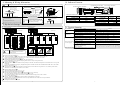
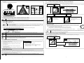
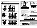
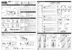
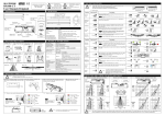
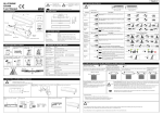
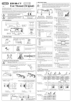
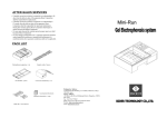
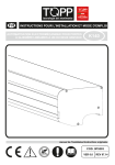
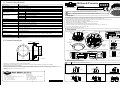
12. Technical Specifications
Motion & Presence
Sensor
Model Name
HR85
Detection Method
Active Infrared Reflection
Installation Height
2.0
Mounting Height adjustment
2
Sensitivity adjustment
H / M / L / Snow (Dip Switch)
Depth adjustment
User Manual
4.0m
3m / 2.5
4m (Dip Switch)
Adjustable Angle
Row
10 (Area Adjusting Screw)
6R / 5R / 4R / 3R / 2R (Dip Switch)
10 (1 Step)
Adjustable Area 1 Wide / Narrow (Area Mask)
Self-Monitoring
ON / OFF (Dip Switch)
1st Row Detection
Doorway / Normal (Dip Switch)
Supply Voltage
AC/DC 12
24V 10%
AC12V : 2.3VA Max DC12V : 120mA Max
AC24V : 2.9VA Max DC24V : 60mA Max
Relay Contact 1a DC50V 0.1A Resistance load
Output
Output Holding Time
Operating Temperature
Approx. 0.5 seconds
2s / 10s / 60s / (Dip Switch)
(Set to 2s / 10s / 60s : 6 rows set at the same time.)
(Set to
the period is infinity in case of the 1st, 2nd, 3rd Row, 2 seconds in case of the 4th, 5th, 6th Row.)
6 Frequencies (Dip Switch)
Power Indicator LED : <Power-ON> ON / <2nd Row Overlapped & Self-Monitoring> BLINK
Operation Indicator LED : <Detection> ON / <2nd Row Overlapped & Self-Monitoring> BLINK
Initialization Indicator LED : <During Initialization> ON / <Adjustment Mode> BLINK
-20
+60
Weight
Approx. 310 g
Presence Timer
Frequency
LED Indicator
WARNING
Disregarding this symbol may result in serious injury or death.
CAUTION
Disregarding this symbol may result in injury or damage to equipment.
1. Features
Adjustable Area 2 Wideness (with Prism)
Power Consumption
<Ceiling Internal Mounting Type>
We would like to extend our thanks to you for purchasing this sensor.
Before install this sensor, please read the following instructions carefully.
Adjustable Angle
Width adjustment
HR85
The detection area is made up of 6 rows, each of which has 12 detection spots. This provides a very dense detection area of 72 detection spots.
Using prisms makes it possible to detect wider area. (Mount less than 2.8m in case of using prisms.)
Doorway detection can be set. Either doorway detecting mode or usual activation mode can be selected by Dip Switch.
Under usual activation mode, detection area depth is enlarged.
Angle activation area is adjustable by Area Adjusting Screw not by the way of click.
The narrow/wide area can be adjusted by Area Mask.
6 frequency setting to avoid cross interference between sensors in close proximity.
The sensor is microprocessor controlled, providing programmable Presence Timer. (2, 10, 60 seconds, )
If set to , the period is infinity in case of the Inner 3 Row.
AC/DC 12 24V is applied as Supply voltage.
2. Description
Body
Connector
Ceiling Mounting Plate
Y
Dip Switch Y Manual Seal
Please note that specifications are changed without notice.
<Accessories>
Screen
13. External Dimensions
Fixing Screw
Thickness
0.1
34
Mounting Template
Area Adjusting Screw
Front Panel
Area Mask
Adjusting
Knob
DOOR SIDE
Operation Indicator LED (Red)
Power Indicator LED (Red)
Initialization Indicator LED (Red)
User Manual
Connection Cable
<Option>
Prism
(2 pieces)
Y
150
16.6
58.5
(Unit mm)
Dip Switch Y
Dip Switch X
3. Mounting Precaution
CAUTION
< Disclaimer > The manufacturer cannot be held responsible for below.
1. Misinterpretation of the installation instructions, miss connection, negligence, sensor modification and inappropriate installation.
2. Damage caused by inappropriate transportation.
3. Accidents or damages caused by fire, pollution, abnormal voltage, earthquake, thunderstorm, wind, floods and other acts of providence.
4. Losses of business profits, business interruptions, business information losses and other financial losses caused by using the sensor or malfunction of
the sensor.
5. Amount of compensation beyond selling price in all cases.
Manufacturer
HOTRON CO.,LTD.
1-11-26 Hyakunin-Cho, Shinjuku-Ku, Tokyo, Japan
Phone: +81-(0)3-5330-9221
Fax: +81-(0)3-5330-9222
URL: http://www.hotron.com
SALES Europe
Hotron Ireland Ltd.
26 Dublin Street (2nd Floor), Carlow, Ireland
Phone: +353-(0)59-9140345
Fax: +353-(0)59-9140543
URL: http://www.hotron.com
-8-
Mount the sensor by following information below.
1. Mount between 2.0 4.0m. Mount less than 2.8m
in case of using Prisms.
2.0
3. Do not mount where rain or snow can fall
directly on unit.
5. Do not mount in humid or steamy
environment.
6. Use different frequency settings for sensors in
close proximity. (Maximum 6 sensors)
4.0m
4. Do not mount in an area where reflection of
sunlight will shine on unit.
MP-10169-A
2. Do not leave any objects which may move
in the Detection Area.
'14
-1-
4. Mounting & Wiring Information
WARNING
10. Indicator Function
Drilling may cause electric shock. Be careful of hidden wires inside the ceiling.
1. Cut out the Mounting Template provided into 2. Connect wires
the appropriate size for the sensor.
126
Connector of the Unit
130 mm
300
Wiring Cable
Yellow
Yellow
Gray
Gray
500 mm
Output
Door
Y
Turn clockwise
CAUTION
7. Sensitivity Settings (Pre-caution on Power-ON)
Initialization Indicator LED
6. Attach the Front Panel to the body.
Turn clockwise
5. Dip Switch Settings
6. Adjusting the detection area
If there is the wiring inside the
ceiling, install the body more
than 1m away the wiring.
During
After
Adjusting Mode
Initialization Indicator
ON
OFF
Blink
5. Dip Switch Settings
Please read followings and understand the functions well to do the proper settings.
Dip Switch X
ON 1
2
Presence Timer
3
4
6
7
8
ON 1
Default Setting
Quantity of
Detection Rows
Frequency
2
3
Sensitivity
4
Mounting Height
Self-Monitoring
6R
A
H
2
3m
ON
Doorway
OFF
10s
5R
B
M
2.5
4m
OFF
Normal
ON
3
1
4R
C
L
3R
D
Snow
2R
E
2
3
4
5
7
5
6
2
6R
6
4
Door operates
intermittently.
Door operates when
no-one is present.
1
F
Door does not
operate.
Default Setting
6
2s
60s
Cause
Problem
5
2R
Adjustment
1st Row Setting - Doorway
8
Operation Indicator / Power Indicator LED
Operation
Power
Indicator
Indicator
Pre-Power ON
OFF
OFF
Power ON
OFF
ON
Detecting
ON
ON
2nd Row Overlapped
Both Blink
Self-Monitoring
Alternate Blink
11. Trouble Shooting
Dip Switch Y
5
1st Row Setting - Normal
Solution
Sensor Connector.
Tighten connector or reconnect.
Power Supply Voltage.
Apply proper voltage to the sensor.
Sensor is very dusty or covered with raindrops etc.
Clean the sensor. (Do not use thinner or alcohol to clean sensor.)
Sensitivity is too low.
Increase sensitivity by adjusting <Dip Switch Y 1 2>.
Detection area incorrect.
Adjust Dip Switch and Area Mask.
Moving objects in the detection area.
Adjust detection area or move away the moving object.
Detection area too far from the Door, detecting
people passing by.
Adjust Dip Switch and Area Mask.
Sensitivity is too high.
Decrease sensitivity by adjusting <Dip Switch Y 1 2>.
Another sensor is installed near by.
Ensure different frequency setting for each other.
The condition of Detection Area is varying.
*Dust / Dirty
*Spread out / Remove a mat
*Snow (footprints)
Detection State may continue during the time setting for presence
detection (the Door remains open) and becomes normal afterward.
Set the presence detection time shorter, re-set the power supply.
After rechecking, there is still a problem, please contact us or your dealer.
CAUTION
1
2
3
4
5
6
7
8
In case that you carry out settings not in
a way mentioned here, mal-function
will be occurred.
Door
Side
6 5 4 3 2 1
R R R R R R
Door
Side
2
R
Door
Side
1
R
Presence Timer (Dip Switch X 1 2)
The sensor will detect a stationary object only for the time set by the Presence Timer. (2s, 10s, 60 seconds, )
If set to , the period is infinity in case of the 1st, 2nd, 3rd Row, 2 seconds in case of the 4th, 5th, 6th Row.
Quantity of Detection Rows (Dip Switch X 3 4 5)
Pattern Depth is adjustable by selecting 2R / 3R / 4R / 5R / 6R (all rows).
If set to <adjustment>, mode is special for adjusting and the inner row only is valid. (please see 6.2)
Frequency (Dip Switch X 6 7 8)
When more than two sensors are installed in close proximity to each other, select different frequencies for each sensor from A to F to prevent
interference.
If you used our H/MH/ML/L 4 frequency changed model, please be noted H coincides with A and MH with B and ML with C and L with D.
Sensitivity (Dip Switch Y 1 2)
Normal position is <M>. If the Door operates even though no person is in the detection area, please set to <L> (Sensitivity will be lower).
When there is an influence by snow or insects, set to <Snow>.
Mounting Height (Dip Switch Y 3)
Adjust the mounting height 2
3 m or 2.5
4 m.
Doorway Detection when closed (Dip Switch Y 4)
Doorway Detecting mode when 1st Row Setting (Dip Switch Y 5) is set to <Doorway>.
ON : Detects Doorway when the Door is closed. Normal position is <ON>
OFF : Not detect Doorway when the door is closed. Combined with other security systems, <OFF> is useful.
1st Row Setting (Dip Switch Y 5)
Doorway : Detects Doorway realizing the Door movement. Normal position is <Doorway>.
Normal : Detects as an usual Activation Row. In this case, adjust the detection area of the 1st Row away from the door.
Self-Monitoring (Dip Switch Y 6)
Self diagnostic function can be selected.
-2-
Power Indicator LED (Red)
Initialization Indicator LED (Red)
Power
Gray codes used for Power, yellow codes used for
Output. Both do not have polarity of electrode.
5. Please see 8. Verification of Operation to confirm
operations.
4. Dip Switch Settings and adjustments.
Operation Indicator LED (Red)
3. Mount the body into the ceiling by Fixing
Screw.
-7-
5.1 1st Row Detection (Doorway Detection Mode)
3. Area Mask
Detection Area can be adjusted using Area Mask.
When the 1st Row is used for the detection of doorway, please set Dip Switch as follows.
Dip Switch Y 5 1st Row Detection
Even after setting 1st Row to <Doorway>, if the door still closes, set the detection area as
follows not to detect the door.
Doorway
Just under
the sensor
Front
View
Top
View
Side View
Top View
Door Side
Doorway Detection Row
Door
door
Fixed glass sheet
In the position of NARROW, Area Mask
is seen in white over the lenses.
L
N
N
6
R
R
5
R
4
R
3
R
2
R
1R
2R
6R
1
R
Dip Switch Y 4 Doorway Detection when closed
To be deleted
by <L> Area Mask
N : NARROW W : WIDE
To be deleted
by <R> Area Mask
To be deleted
by <L> Area Mask
To be deleted
by <R> Area Mask
ON
Doorway detection function can be selected as follows.
OFF
Area Mask Tuning Knob
Please turn Area Mask to stop in
click
7. Sensitivity Settings (Pre-caution on Power-ON)
CAUTION
1
2
Before applying power, please check the wiring again and follow instructions below.
After installation of the sensor, please check sensitivity Dip Switch set to <M>
(Dip Switch Y 1 2. Default is <M>.)
Please adjust the Mounting Height.
(Dip Switch Y 3. Default is <2.5
4m>.)
CAUTION When the actual Mounting Height is 2.5
<2.5
3
door
3m, either setting <2
6
R
3m> or <2.5
4m> can be selected. In this case, Default
4m> is recommended.
Sensitivity is adjusted automatically. Before applying power, please check no objects (stepladder, tools etc.) are left in the detection area.
After applying power, do not enter into the detection area within 10 seconds.
(If there is a person inside the detection area within the detection seconds, setting sensitivity cannot be made properly.)
Do not enter into the detection area within 10 seconds
Power
ON
10 seconds
5
R
4
R
3
R
2
R
Detecting doorway when the door closed.
(the sensor is OFF.)
Normal position is this.
door
1
R
6
R
5
R
4
R
3
R
2
R
Not detecting doorway when the door
closed. (the sensor is OFF.)
Combined with other security systems
<OFF> is useful.
1
R
Initialization
Initialization of a sensor (door learning process) is necessary for doorway detection. This process is made every time of
Power-ON, it is completed after the sensor has learned the movement of persons 2 or 3 times. The state of Initialization
process is confirmed with Initialization Indicating LED.
Under Initialization : Initialization Indicating LED flashes. Not detecting doorway.
After Initialization : Initialization Indicating LED does not flash. Detecting doorway.
The 2nd
6th Row except Doorway Row are not necessary for the Initialization process above, and they
operate in the same manner of usual reflection sensors.
Presence
Detection
Initialization Indicating LED
CAUTION If only the detection of Doorway Row occurs, and has judged malfunction of the door, re-start the initialization process.
Initialization Indicating LED starts flashing when initialization.
CAUTION If there is a moving object in the detection area after Power-ON, the sensor will not be in Presence Detection mode.
After removing of the person or object, the sensor will be in Presence Detection mode in 7 seconds.
CAUTION When set to
, please be noted there would be a case the door remains open if the surface of the detection floor changed suddenly.
In that case, please turn off the power and try again.
While carrying out followings, please turn off the power. If you carry out followings when the power is ON, the door will remain open
5.2 1st Row Detection (Usual Mode)
When the 1st Row is used as the usual detection, and activation area (detection depth area) is to be enlarged,
please set detection area as follows.
Dip Switch Y 5 1st Row Detection
CAUTION for the period of Presence detection time you set. And also the Initialization will start again.
Normal
In case of alteration of Detection Area, or re-adjustment of Sensitivity.
In case of laying or removing a cloth/resin mat in the Detection Area.
Top View
Side View
8. Verification of Operation
1. If mounting and various settings are completed, the power and confirm
the performance of detection area.
2. If the door does not operate normally, turn off the power and re-set
the detection area.
3. If the door does not function normally after the above procedure,
adjust Dip Switch.
4. When adjusting the detection area or sensitivity by Dip Switch,
turn off the power first.
When re-setting, turn on the power according to <7. Sensitivity Settings
(Precaution on Power-ON)>.
(1) When the sensor does not detect a person in the detection area,
adjust <Dip Switch Y 1 2> (H) side.
(Sensitivity increases)
(2) When the sensor detects a person even if no one exists in
the detection area, adjust <Dip Switch Y 1 2> (L) side.
(Sensitivity decreases)
Door
door
How to set sensitivity :
Fixed glass sheet
The 1st Row detection area should
not be overlapped with the door.
6
R
5
R
4
R
3
R
2
R
1R
2R
6R
1
R
Initialization process is not necessary in this case. Initialization Indicating LED does not flash even after Power-ON.
9. Self-Monitoring
Self-Monitoring means the sensor is equipped with microprocessor control function and continuously monitors itself.
When Self-Monitoring determines that the sensor has malfunctioned, Operation Indicator LED and Power Indicator LED will blink alternately with the
door remained open. In this case, please replace the sensor immediately.
ON / OFF of Self-Monitoring can be set with Dip Switch.
CAUTION If the floor of Detection Area is specular surface, Self-Monitoring may function. In that case, set Self-Monitoring <OFF>
with Dip Switch.
-6-
Usual Detection Row
-3-
<Top View>
6. Adjusting the detection area
Without Prism
Adjust the detection area according to the following diagrams.
With Prism
Door Side
Door Side
W3
W1
The illustrated detection areas represent the actual position of the infrared beams. The actual detection area observed will vary depending
CAUTION
on the sensor installation environment, objects been detected and sensor settings. Please confirm the detection area and sensitivity after
installation without fail.
CAUTION Do not touch the surface of the lens while adjusting. If the lens becomes dirty, wipe the lens clean by using neutral detergent.
1. Detection Area Pattern
<Side View>
Door Center
Area Adjusting Screw
1.0
0.3
0.5
0.5
0.5
(Unit : m)
1.0
1.5
2.0
2.5
W2
W1
Side View
H
2200
2500
3000
4000
2.0
Door Side
10
3.0
(Unit : mm)
D
1100
1250
1500
2000
Depth “D“ is unchanged
When using prisms : Mounting height is MAX 2.8m
Detection by Area Mask is prohibited
Set Dip Switch X 3 4 5 to <Adjustment>
In this setting, only 2nd Row is valid.
Initialization indicating LED blinks.
3 4 5
<Front View> Without Prism
(Unit : m)
2.5
10
5
W3
1000
1100
1300
1730
2nd Row
Adjustment
4.0
5
W2
1550
1750
2100
2800
Set Dip Switch Y 5 to <Doorway>
10
3.5
10
W1
2100
2400
2850
3800
(Unit : mm)
W1
2560
2920
3270
Prism does not work
2. Adjusting Detection Area
Adjust the 2nd Row when Doorway detection function is ON.
2.5
10 for both sides
(RIGHT / LEFT)
H
2200
2500
2800
More than 2800
2.0
1.5
1.0
0.5
0.5
1.0
1.5
2.0
2.5
Front View
Scale Marks inside
Referring to the Area Adjusting Estimation List below, fix the approximate
angle by Area Adjusting Screw.
Adjust 2nd Row not to overlap with the Doorway with the door opened.
(See the figure on the right)
Detection Area should be adjusted looking at Indicator LED by using
a beam finder or reflection sheet.
Just under the sensor
2nd Row should be not to detect Door.
Turn Area Adjusting Screw as below.
Area Adjusting Screw
Towards Door Side
3
Towards Outside
2.0
A 360 roll of the Screw adjusts Depth Angle 3 .
2.5
4000mm
Moving distance on the floor
200mm
100mm
150mm
After finishing setting of 2nd Row, adjust Dip Switch X 3 4 5 as necessary. Re-set Power-ON after confirming no one is in the detection area.
When Open/Close the door, if hunting occurs or caution Indicator LED regarding the 2nd Row overlapping with the door blink (Both Power
Indicating LED and Operation Indicating LED blink at the same time), adjust the detection area away from the door by Area Adjusting Screw.
3.0
Door Side
Lens Box (Upper Hatch) for adjusting
Detection Area. (RIGHT / LEFT)
Moving distance by 360 roll of the Screw
Mounting height
2000mm 3000mm
10
10
3.5
Area Adjusting Estimation List
Distance between Door
Center and Sensor
4.0
Mounting Height
2000mm
3000mm
4000mm
<Front View> With Prism
Attach the prisms covering the lenses.
(Unit : m)
2.5
2.0
1.5
1.0
0.5
0.5
1.0
1.5
2.0
2.5
Front View
CAUTION
300mm
6
3
2
400mm
500mm
9
5
3
10
7
5
After adjusting Detection Area, be sure to Re-set Power-ON, and carry out Initializing and Automatic Sensitivity Adjustment again.
st
st
CAUTION When selection <Normal> of 1 Row Setting, the 1 Row detects in an usual activation mode.
Please adjust the 1st Row not to detect the Door.
With Prism
How to attach prisms (as an option)
CAUTION
2.0
10
2.5
Door Side
10
Both sides of the prism lens are
set into the lens box.
CAUTION Mounting height is less than 2.8m in case of using
prisms.
CAUTION Setting Area Mask <Wide> in case of using
Each of the
2 prisms are
attached.
prisms.
CAUTION Check whether the prisms are set firmly after
fixing them.
If the prisms become dirty, wipe them clean by
2.8
CAUTION using neutral detergent.
Do not use thinner or alcohol.
-4-
-5-