1
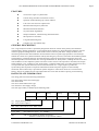
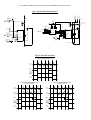
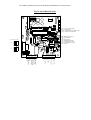
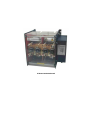
USER MANUAL STA SERIES THYRISTOR STACKS FOR TRANSFORMER COUPLED LOADS 80A -600A Caledon Controls Ltd Unit 2 Block 4 Castlehill Industrial Estate Carluke Lanarkshire, Scotland ML8 5UF Telephone 01555 773355 Fax 01555 772212 CALEDON CONTROLS LTD K620W1R1.DOC, January 1997 STA SERIES THYRISTOR STACKS FOR TRANSFORMER COUPLED LOADS Table of Contents Features...............................................................................................................2 General Description.............................................................................................2 Rating Plate Information .....................................................................................2 Safety Information ...............................................................................................3 Table Of Fuse Types ............................................................................................3 Compliance With Standards ................................................................................3 Specifications ......................................................................................................4 Environmental .......................................................................................4 Electrical................................................................................................4 Control Signal Inputs And Outputs ........................................................4 Installation ..........................................................................................................5 General Requirements............................................................................5 Recommended Power Cable Sizes ..........................................................5 Mechanical ............................................................................................6 Wiring ...................................................................................................6 Commissioning ...................................................................................................7 Access To The Driver Card ....................................................................7 Dil Switch..............................................................................................8 Minimising Transformer Inrush Current ................................................8 Operation ............................................................................................................9 Covers....................................................................................................9 Switching On .........................................................................................9 Led Indicators ........................................................................................9 Demand Signal ......................................................................................9 Line Synchronisation ...........................................................................10 Use With The Amot 130 ......................................................................10 Fault Finding .......................................................................................11 CALEDON CONTROLS LTD Manual Issue Number R1 Page 1 STA SERIES THYRISTOR STACKS FOR TRANSFORMER COUPLED LOADS Page 2 FEATURES Versions for single or 3-phase loads Current rating from 80A to 1000A air cooled Operation without derating up to 50oC ambient Low cost 2-line control of 3-phase load Minimum radio frequency emissions Minimum waveform distortion No power factor degradation Simple installation, commissioning and maintenance Microprocessor controlled Long life ball-bearing fans Compact size, only 290mm deep GENERAL DESCRIPTION This range of thyristor stacks is specifically designed for burst fire control of the primary of transformer coupled loads in heating applications. A typical application example is in high temperature furnaces with low resistance graphite heating elements. These stacks switch on near the peak of the voltage waveform, thus minimising transient flux and transformer inrush without recourse to phase angle operation. This technique enables the control of a 3-phase transformer load by switching only two lines, and causes the minimum possible line disturbance, waveform distortion and radio frequency emissions. Special drive techniques ensure the minimum possible rfi associated with zero crossing commutation of the thyristors, enabling the units to be used with confidence in emc compliant systems. The driver control circuit is microprocessor controlled, and accepts either analogue (1-5V, 4-20mA) or logic input signals. A separate enable input is provided, which can be used in conjunction with system interlocks, current overload monitor etc. A logic output is provided for synchronising other thyristors if required. Semiconductor fuses and power supplies are electronically monitored, and an alarm relay is provided for system integration. These units do not have a current limit facility, and are not suitable for use with loads which have a low cold resistance requiring current limiting. RATING PLATE INFORMATION The rating plate carries the following information:The rated voltage of the main load supply The rated current The correct semiconductor fuse type The rated driver card supply voltage. The stack type number, as defined by the following table:Type Controlled Lines Current Rating Voltage Rating Fan and Driver Supply Options STA 101 Single phase operation 203 2-line control 3-phase 80A, 125A, 160A, 200A, 315A, 400A, 600A 250V, 440V, 480V, 660V* 115V, 230V (Fan and driver supply, - AC 50/60Hz) BUS (Lid cut outs suitable for busbar connections otherwise rounded slots are provided for cables). CALEDON CONTROLS LTD Manual Issue Number R1 STA SERIES THYRISTOR STACKS FOR TRANSFORMER COUPLED LOADS SAFETY INFORMATION Thyristor stacks must never be used as a means of supply isolation, as even in the 'off' state lethal leakage currents will flow. An independent means of isolation, complying with local standards must always be fitted. The clear polycarbonate cover provides protection against accidental contact with live parts, and must never be removed unless the main supply has been isolated elsewhere. Busbars and circuitry on the printed circuit boards under this cover carry the full line voltage. The LED indicators must not be taken to indicate that the supply is isolated. In the event that the driver supply is switched off, or the driver supply fuse is blown, the LEDs will not be lit, but the main line supply may still be live. The lid on the driver box must not be removed unless the driver supply is isolated. TABLE OF FUSE TYPES Checking or changing of any fuse must not be attempted unless both main and driver supplies are isolated. To do so is extremely dangerous, and may also cause damage to the stack. The following semiconductor fuses are used. The type numbers indicated are supplied by Bussman. The quantity, where indicated, is per phase. Current Rating 80A 125A 160A 200A 315A 400A 600A Fuse Type BS 88 110EET 160EET 225FM 315FM or 2 x 225FM or 2 x 315FM 4 x 315FM or DIN 43653 size 00 170M2619 1 x 170M2671 2 x 170M2671 The following fuses are used to protect the control circuits. Supply transformer primary (fitted on pcb in driver box) 115V supply 230V supply High Voltage isolation tx primary (fitted on high voltage board) 4 off 5 x 20mm, 500mA type T 5 x 20mm, 250mA type T 5 x 20mm, 800mA type T COMPLIANCE WITH STANDARDS Low Voltage Directive The stacks are designed to meet the requirements of international standards and are CE marked in compliance with the European Low Voltage Directive. The following standards have been applied in whole or in part in the design of these units: EN 60947-1, EN61010-1, pr EN50178 Electromagnetic Compatibility The control circuits of the unit meet or exceed the requirements of EN 50 082 part 2 and EN 50 081 part 2 (immunity and emissions for industrial environment). The thyristor drive circuitry is designed to minimise conducted emissions associated with the load current, and additional filtering will not normally be necessary. Application notes provide information on system design for compatibility. To ensure that the noise limiting characteristics of the drive circuitry operate correctly in 3-phase systems, the load currents must be reasonably balanced (within 15%). CALEDON CONTROLS LTD Manual Issue Number R1 Page 3 STA SERIES THYRISTOR STACKS FOR TRANSFORMER COUPLED LOADS SPECIFICATIONS ENVIRONMENTAL Ambient Operating Temperature Storage Temperature Relative Humidity Pollution (IEC 664) Elevation 0-50oC -25 to +70oC 0-95% non condensing Temporary condensation may occur, but not normally while equipment is operating). Derate current rating 1% per 100 metres above 200 metres ELECTRICAL Rated Supply Voltage (Load) Rated Current Supply Frequency Rated Impulse Withstand Voltage (IEC 664) 250V, 440V, 480V, 660V +10%, -50% As ordered. Rated current is specified at 50oC ambient. 50Hz or 60Hz +/-8% 4KV CONTROL SIGNAL INPUTS AND OUTPUTS Analogue input control signal Logic input control signal Logic output signal Enable input +5V supply output Alarm relay output 1-5V. (4-20mA in conjunction with external 250 ohm burden resistor). Max 30V input. Switching threshold >3V on, <2V off. +12V (approx.) signal, synchronised to stack turn on. Contact closure, npn pull down or link required to enable the stack. Available to power 10K potentiometer for manual control. Volt free changeover contacts, rated 250V AC 1A operate on loss of power, load supply, loss of phase lock, heatsink overtemperature. LED Indicators 1 2 3 4 5 6 7 Auxiliary driver power supply present. Heatsink temperature within range. Presence of load supply voltages. Phase lock (control system synchronised to load supply voltage). Enable (1-4 correct, and external enable signal present). Demand signal (Stack is asking for current to be supplied to load). Alarm (one of 1-4 is not correct). Control Parameters Load burst fire cycle time at 50% duty cycle Burst fire start angle 15 seconds (Other cycle times available on request). Adjustable 30-90o after zero crossing, by potentiometer. After loss of power while load current is flowing, or change of phase rotation, or supply frequency, first switch on is ramped over ten cycles in phase angle mode on line 1, to reset transformer magnetisation. Notes All units require an auxiliary power supply of 115 or 230V +10%, -15%, 50/60 Hz. to power the driver card and the fans where applicable. This supply does not need to be phase related to the main load supply. All units apart from the 80A unit are fan cooled. All units are fitted with snubber capacitors, MOV transient over voltage protection, semiconductor fuses and emc filter capacitors. Above 600A units can be sized to meet your requirements. * 660V units. Note that impulse withstand voltage is restricted to 4kV and emc filter capacitors are omitted. Consult us. CALEDON CONTROLS LTD Manual Issue Number R1 Page 4 STA SERIES THYRISTOR STACKS FOR TRANSFORMER COUPLED LOADS INSTALLATION GENERAL REQUIREMENTS The following notes are a guide to ensuring sound system design, and compliance with the requirements of the European Low Voltage Directive. The stacks should be installed in a cabinet requiring a tool to gain access, and access should be restricted to suitably trained and qualified personnel. Provision should be made to exclude conductive pollution (eg graphite dust) from the cabinet, and to avoid condensation. Caledon thyristor stacks are designed with an impulse withstand voltage of 4kV. This meets the requirements of IEC and European standards for installation category 3, and supply voltage (line to earth) up to 300V (AC RMS). This corresponds to 520V line to line on most distribution systems, in which the supply transformer is star connected with earthed star point. This does not preclude the use of the stacks in higher voltage systems (provided the thyristor devices are suitably rated), but precautions may be necessary (surge arrestors) to limit the expected impulse voltage level, to ensure systems compliance with the above standards. All the STA series thyristor stacks incorporate integral semiconductor fuses. These are intended to provide short circuit protection for the thyristor devices, by limiting the peak half cycle surge current and total energy let through. They only provide limited protection against long term overload. The stack ratings are co-ordinated with standard HBC fuse values, and the supply cables should be protected with gG fuses or circuit breakers rated the same as, or lower current than the stack. All the stacks with fan cooling also incorporate automatically resetting thermal cut outs, which monitor the heatsink temperature, and ensure that they do not rise to an unsafe temperature. The stacks are rated for a maximum ambient operating temperature of 50oC. This applies to the ambient air temperature entering the heatsinks at the base of the stack. The design of an installation must however take into account the ratings of cables and other switchgear within the cabinet. Elevated temperatures also shorten the life of some electronic components, notably electrolytic capacitors, which dry out. A major cause of elevated temperatures in a cabinet containing thyristor stacks is the power dissipated by the thyristor devices, which may be approximated in watts as 1.5 to 2 x (RMS current) x (Number of controlled lines). The exhaust air temperature from the stack will be higher than ambient by up to 20oC. It is not good practice to mount other items of control gear directly in the exhaust airflow. In particular the current carrying capability of fuses or circuit breakers will be significantly reduced if this is done. A tidy solution is to mount circuit breakers or fuses supplying the stack on a sub-chassis mounted forward from the main chassis on which the stack is mounted. The exhaust air then passes behind these components. Thyristor stacks should not be mounted one above the other, as this will significantly derate the upper unit, which, for rating purposes will be operating in an ambient equal to the exhaust air temperature of the lower unit. Heat from the thyristors, together with that dissipated by the semiconductor fuses will also raise the temperature of the busbars to which outgoing cables are connected, and high temperature cables should be used. The cross-section of the cables and their ventilation will influence the temperature of the connection studs, and the guide below shows recommended minimum cross sections. Consideration must be given to fault conditions. In particular a short circuited thyristor could result in loss of control of the load current. If this could cause a dangerous temperature to arise in the controlled load, then an independent means of monitoring and switching off the current must be provided. This could take the form of an independent over-temperature policeman controlling a contactor or under voltage release on a circuit breaker fitted in the main supply lines. This is a requirement of EN 60519-2 Safety in electroheat installations, part 2: Particular requirements for resistance heating equipment, para 13.3. This standard requires independent protection of electronic controllers and frequently operated contactors. Provision for independent isolation of the power circuits must be provided. RECOMMENDED POWER CABLE SIZES The following is a guide only, as installation conditions will vary. A maximum control cabinet temperature of 50oC has been assumed, with cables routed in free air in the immediate vicinity of the stack, and passing into trunking in groups of three. The cable protective fuse or circuit breaker rating has been assumed to be equal to the stack current rating. For currents up to 200A a cable with a maximum operating temperature of 85/90oC has been assumed. For 315A and above a cable with a maximum operating temperature of 125oC has been assumed. We recommend the use of cables with cross linked polyolefin insulation. CALEDON CONTROLS LTD Manual Issue Number R1 Page 5 STA SERIES THYRISTOR STACKS FOR TRANSFORMER COUPLED LOADS STACK RATING CABLE X SECTION STACK RATING CABLE X-SECTION 80A 125A 160A 200A 25mm2 50mm2 70mm2 120mm2 315A 400A 600A 120mm2 2 x 120mm2 2 x 120mm2 MECHANICAL The stack must be mounted vertically, with the fans at the bottom of the unit. Allow a minimum of 100mm above and below the stack to allow free airflow. The stack is mounted using 4 off M6 (6mm diameter) screws. For fixing centres see the attached drawing. For convenience the two bottom screws may be screwed loosely into the bulkhead to which the stack is to be mounted, and the stack hooked over them, before inserting the upper two screws and tightening. WIRING Typical wiring schematics are shown in figure 1. To ensure that the stack insulation is not compromised by the installation, where cables associated with different circuits are grouped together, the insulation of the cables must be suitable for the voltage of the highest voltage circuit in the group. Power Cables Use the guide above in determining cable type and cross section. Cables should be connected using crimp terminals. Up to 125A stacks have 8mm studs. 160A to 315A have 10mm studs, 400A upwards have 12mm studs. A protective earth connection of suitable cross section should be made to the 8mm stud at the top RHS of the unit. Line 3 Connection (STA 203 units for 3-phase load) The stack controls only 2 of the 3 lines. A connection for the third line is however required for line synchronisation, and connection of integral emc suppression capacitors. This third line is connected to the terminal marked 'line 3', adjacent to the 'load 1' terminal. The connector is of the screwless cage clamp type, and will accept cables from 0.75mm2 to 4mm2 cross section. To insert the cable, insert a small screwdriver in the hole in the terminal adjacent to the cable entry, and depress while inserting the cable. Release the screwdriver. Note that the screwdriver is in electrical contact with the conductor, and should not be inserted while the circuit is live! The cable connected to this terminal should be fused with a 5A fuse. Although the main terminals are labelled 'Line 1', 'Line 2', the actual phase rotation is not important, as the control electronics monitors phase rotation and adjusts accordingly. Line 2 Connection (STA101 units for single phase load) A connection is required to the line supplying the unswitched side of the load, for line synchronisation, and connection of integral emc capacitors. (This may be a second line, or the supply neutral, depending on load connection). This connection is made to the terminal marked line 2 adjacent to the 'load 1' terminal. The connector is of the screwless cage clamp type, and will accept cables from 0.75mm2 to 4mm2 cross section. To insert the cable, insert a small screwdriver in the hole in the terminal adjacent to the cable entry, and depress while inserting the cable. Release the screwdriver. Note that the screwdriver is in electrical contact with the conductor, and should not be inserted while the circuit is live! If this connection is to a supply line (not the neutral) then the cable should be protected with a 5A fuse. Control Cables All control cables are wired to two connectors on the side mounted control box. These connectors are pluggable, and may be removed for maintenance purposes etc. They are suitable for cables up to 2.5mm2 cross section. It is not specifically necessary to use screened cable for the wiring of control circuits to meet the required emc immunity level. We recommend that good wiring practice be followed within the control panel in which the stack is installed, taking care to avoid running signal wiring parallel to high current or switching circuits as far CALEDON CONTROLS LTD Manual Issue Number R1 Page 6 STA SERIES THYRISTOR STACKS FOR TRANSFORMER COUPLED LOADS as is reasonably practical. If signals are sourced from outside the panel we recommend that screened cable be used outside the panel, and the screen earthed at the point of entry to the panel. This is most conveniently undertaken using special glands, but if pigtails are used these should be earthed to the metalwork as directly as possible. If screened cable is used between the entry to the panel and the stack, then the screen should be earthed to the metalwork near the stack. Incorrect earthing of screened cables can result in worse performance than using non-screened cables. Terminal No. Description Application and Wiring Details 1:1 Enable Signal This terminal must be linked to terminal 1:2 to enable the stack to supply current to the load. The link may be performed by a volt free relay contact, or an npn open collector pull down, and used as a system interlock. Loss of this enable signal can be set to cause an alarm (see DIL switch settings). 1.2 0V 1:3 Control Input + 1:4 0V 1:5 Logic Input This terminal accepts a logic input control signal. Maximum signal input 30V. <2V, stack is off; >3V stack is on. Use terminal 1:4 for the 0V return. Note that the stack has minimum on and off timers of 1 second, which prevent unduly rapid cycling. 1:6 +5V An output for use with a 10k ohm potentiometer for manual control of the stack. 1:7 Logic Output An output which is synchronised to the switching on of the load current, and may be used in conjunction with the logic input of a second stack to synchronise firing. See figure 2. Use terminal 1:8 for the 0V return. 1:8 0V 2:1 Alarm Common 2:2 Open in Alarm 2:3 Closed in Alarm 2:5 Supply L Driver circuit supply connection. The supply voltage is either 115V or 230V AC 50/60Hz, as specified in the stack part number, and on the rating plate. The supply wiring should be protected with a maximum 5A anti-surge fuse. The supply need not be phase related to the main terminal supply. 2:7 Supply N Driver circuit supply neutral (return). This terminal accepts an analogue control signal, 1-5V or 2-10V, depending on the DIL switch setting. Use terminal 1:4 for the 0V return. A 4-20mA signal may be connected if a 250 ohm burden resistor is connected across the two terminals (set DIL switch to 1-5V). Volt free relay contact, together with terminals 2:2 and 2:3. The alarm contacts are rated at 250V AC, 30V DC, 1A. The contacts are unsuppressed. Circuits connected to the alarm relay should be protected with a maximum 5A fuse COMMISSIONING ACCESS TO THE DRIVER CARD Access to the driver card is required if the DIL switch settings need changing, or to check the driver supply fuse or voltage setting. CALEDON CONTROLS LTD Manual Issue Number R1 Page 7 STA SERIES THYRISTOR STACKS FOR TRANSFORMER COUPLED LOADS To gain access undo the two wing-nuts which secure the driver lid, and slide the lid away from the unit. The driver box may then be slid forward and disengaged from the retaining washers. The protective earthing cables may be unplugged at the stack end. These MUST be replaced when refitting the box. The driver supply voltage is defined by the fan voltage, and is noted on the stack rating plate. It cannot be changed without changing the fans. The driver supply transformer is fitted with universal windings, and the correct connection is chosen by the position of the connector to the printed circuit card. See figure 3. DIL SWITCH A 4-way DIL switch may be used to configure modes of operation. When the unit is supplied all 4 switches are OFF. The function of the switches is as below:1 Input Range If switched on changes the required input signal from 1-5V to 2-10V. 2 Not used 3 Mode Sets the input control signal type. When off the required input signal is analogue. When on the input signal is logic. Note that the chosen signal must also be wired to the appropriate terminal. 4 Alarm function If switched on causes the alarm to operate when the external enable signal is lost, in addition to the standard alarm conditions. MINIMISING TRANSFORMER INRUSH CURRENT To minimise transformer inrush current, the point in the mains cycle at which the thyristors are switched on should be optimised. A potentiometer, 'start angle adjust', accessible through a hole in the front cover of the driver box, is provided to make this adjustment. The optimum point will be just before the peak of the voltage/current waveform on the first phase to be switched on. This may be monitored on a storage oscilloscope connected to a current transformer on the load 1 cable. The oscilloscope may be synchronised to the logic output signal from the stack. If suitable equipment is not available, then the potentiometer should be set to approximately one quarter way from the fully anti-clockwise position to the clockwise position. To fully observe the load currents, if desired, two current transformers are required on three phase systems, to monitor load 1 and load 2 current. The waveforms observed will depend on the phase rotation. There are two possible phase rotations, here called A and B. These are indicated by the flashing phase LED when auxiliary power is first applied. If Phase 1 LED is flashing, then rotation is A. If Phase 2 LED is flashing, then rotation is B. It is important that the current transformers should both be phased the same, when the current waveforms should appear as in figure 2. To optimise the inrush, set the controller to 50% duty cycle, and rotate the potentiometer slightly between bursts, observing the switch on current, starting from the fully anti-clockwise condition, until the optimum point is found. Note that the first time the controller fires after powering up, the current on load 1 may be ramped up in phase angle mode. This is because for correct operation the point of switch off of the current must also be controlled. If the switch off is not controlled, an inrush may occur even when the switch on point is correct. To prevent such an inrush from potentially blowing a fuse, the controller monitors the manner in which the current was last switched off. If this was not done synchronously, for example because the power failed, or the operator threw the main switch while current was being drawn, then the controller will ramp the thyristors on line 1 in phase angle mode on the first switch on. A similar action is taken if the phase rotation or the supply frequency have changed. The status when the driver supply is removed is stored in EEPROM. To minimise the number of times this occurs during normal operation, power should never be removed from the controller (Main load or driver power) unless the current demand is zero. If the stack is to be transferred from use with one transformer to another, then it is important that when the transformer is first fired up, the stack should operate in phase angle mode, to reset any residual magnetism. To ensure this, the stack may first be powered without the transformer being connected, and a control signal applied so that the stack is demanding load current. While load current is being demanded, switch off the power to the stack. CALEDON CONTROLS LTD Manual Issue Number R1 Page 8 STA SERIES THYRISTOR STACKS FOR TRANSFORMER COUPLED LOADS OPERATION COVERS For safety reasons the stack should not be operated with the clear polycarbonate cover or the driver box cover removed. Additionally, the fans direct a proportion of their airflow over the high voltage card and semiconductor fuses, and this cooling action, particularly of the fuses will be impaired if the cover is removed. SWITCHING ON The main and driver power supplies may be switched on in any order. The stack will not supply current to the load until all supplies are present. The fans will run all the time the driver supply is present. LED INDICATORS The normal operation of the stack is displayed on 8 LED lamps, whose function is as follows:LED No. Description Function 1 Power Illuminates to show that the driver power is present. 2 Temperature Illuminates when all the heatsinks are within the correct temperature band. Will extinguish if a heatsink over heats. 3 Phase1 Illuminates when line voltage is present between line 1 and line 3. When the driver supply is first switched on, this LED may flash, indicating that VL1L3 leads VL2-L3. Will extinguish if the line voltage is not present, or the line 1 fuse has blown. (In 3 - phase systems) 4 (In single phase systems) Illuminates when line voltage is present between line 1 and line 2 or neutral.Will extinguish if the line voltage is not present, or the semiconductor fuse has blown. Phase 2 Illuminates when line voltage is present between line 2 and line 3. When the driver supply is first switched on, this LED may flash, indicating that VL2L3 leads VL1-L3. Will extinguish if the line voltage is not present, or the line 2 fuse has blown. (In 3 - phase systems only) 5 Phase Lock Illuminates when the stack has successfully synchronised to the line supply. The stack synchronises to the voltage between L1 and L3. Will extinguish if phase lock is lost, caused by loss of supply (phase 1 LED also absent), or excessive noise or frequency variation on the supply, or if the supply frequency is out of tolerance. 6 Enable Illuminates when 1-5 are correct, and the external enable is made (link across terminals 1:1 and 1:2. 7 Demand Illuminates when the stack is demanding load current. More information on the demand signal is provided in the next section. 8 Alarm (red) Illuminates when the alarm relay is in the alarm state (de-energised). This LED will be illuminated briefly when driver power is first applied, and subsequently will illuminate 5 seconds after loss of any of 2-5. (An alarm is also generated if the driver power is lost - relay de-energises). If DIL switch 4 is on, it will also illuminate on loss of the external enable signal. DEMAND SIGNAL The stack operates in burst fire mode; ie the load current is either on or off. The start of each burst is synchronised to the line voltage as shown in figure 2. The demand signal is generated internally, in response to the external control signal, which may be either analogue or logic, as defined by the DIL switch setting and the signal connection. CALEDON CONTROLS LTD Manual Issue Number R1 Page 9 STA SERIES THYRISTOR STACKS FOR TRANSFORMER COUPLED LOADS Analogue Control Signal The input signal is 1-5V, and a 50% duty cycle is set when the input is at 3V. The stack is fully off with an input of 1.2V or less, and fully on with an input of 4.8V or more. At 50% duty cycle, one cycle period is approximately 15 seconds. At duty cycles other than 50%, the cycle period becomes progressively longer as the duty cycle increases or decreases. This enables the average power delivered on the cycle to be modulated over a wide band without having unduly short 'on' or 'off' periods. Minimum 'on' and 'off' times of 1 second are superimposed on the basic cycle period, so that if the control signal is rapidly increased or decreased the load is not switched too rapidly. Logic Control Signal The input signal is a voltage which switches the stack either of or on. The maximum input voltage is 30V; <2V the stack is off; >3V the stack is on. The cycle period is set by the switching rate of the external signal, except that the minimum on and off times of 1 second will still apply. The external cycle period can thus not be less than 2 seconds, and in practice must be considerably longer, to achieve a suitable turn down.(ie with a 20 second cycle period the minimum power other than off is 1/20th of full power. The switch on and off is controlled via an interrupt on the microprocessor, to enable rapid response. Thus, for example, 3 single phase stacks could be used to control an open delta load comprising 3 single phase transformers. An analogue control signal could be fed to the master stack, and the logic output of that stack fed to the logic input of the other two stacks. Each stack would then switch on and off at the correct point in the cycle, minimising transformer inrush and maintaining a balanced load. LINE SYNCHRONISATION Correct line synchronisation is imperative if transformer inrush current is to be avoided. To this end the line voltage signal is passed through an active filter network before being passed to the microprocessor, and then a number of strategies are employed by the phase lock algorithm in the presence of noise:If the demand signal is off, no action is taken. If the demand signal is switched from off to on while line noise is present, switch on may be delayed for a few cycles until a reliable signal is obtained, or if a reliable signal is not obtained, phase lock is signalled as lost, and the stack is disabled until it is regained. If the demand signal is on, and noise is detected, but there is no requirement to switch off, no action is taken. If the demand signal is switched from on to off while line noise is present, switch off may be delayed for a few cycles until a reliable signal is obtained. If a reliable signal is not obtained, then switch off occurs anyway, but the next switch on is set to start in phase angle mode. If a phase or the driver supply voltage is lost while the demand signal is high, the next switch on is set to start in phase angle mode. If a phase or the driver supply is lost while the demand signal is low, then no action is taken (other than to signal the condition). USE WITH THE AMOT 130 The AMOT 130 is a panel mounted over-temperature policeman, combined with an auto/manual station. The over-temperature policeman may be used to provide independent monitoring of the load temperature, and in conjunction with a contactor, or under-voltage trip on a circuit breaker, can provide independent switch off of the load current. The auto/manual station, which is wired between the main temperature controller and the stack control input (analogue input only), provides a simple means for the operator to switch control of the heater from the automatic controller, to a manually operated potentiometer on the instrument. An LED bargraph gives visual indication of the level of the power control signal in auto or manual. Combining the two functions in one instrument confers a major advantage. When an over-temperature is sensed the power demand signal is reduced to zero a short time before the alarm relay is operated. Thus, assuming the thyristors are still functioning correctly, the contactor / circuit breaker does not have to break the main load current, and, more importantly in transformer load applications, switch off occurs synchronously under control of the thyristor controller. CALEDON CONTROLS LTD Manual Issue Number R1 Page 10 STA SERIES THYRISTOR STACKS FOR TRANSFORMER COUPLED LOADS If desired, the alarm relay may also be wired to switch off the auxilliary supply to the stack driver circuit. This will mean that in over-temperature the stack fans are also switched off. The AMOT 130 may be used as a simple temperature controller in the event of failure of the main controller, or as a 'night setback' controller, by turning the setpoint down and placing the control signal in 'manual'. By setting the manual power level to an appropriate value the switching required by the 'over-temperature' action is reduced to a minimum, and smooth temperature control is achieved. FAULT FINDING Before attempting to rectify a fault on the unit, it is most important that the information in the section headed SAFETY INFORMATION should be read and acted upon. The following is a guide to first line fault finding. Fault Symptom Possible Cause None of the Driver LEDs light Driver card power supply not present. (Fans will not be running). Fuse on driver card (supply fuse) has blown. (Fans will be running). Temperature LED is not lit A heatsink has overheated. Is the ambient temperature very high? Are the fans running? One of the connections to a temperature sensor is faulty. Phase 1 LED is not lit The line 1 power is not present, or the line 1 semiconductor fuse has blown. Phase 2 LED is not lit The line 2 power is not present, or the line 2 semiconductor fuse has blown. Phase 1 and Phase 2 LEDs not lit Line power is not present, or line 3 power is not present. Phase lock LED is not lit If phase 1 and phase 2 are both lit, then the line supply must be very noisy, or outside the frequency tolerance, or varying rapidly in frequency. Enable LED not lit One of the preceding LEDs is not lit, or the external enable is not made. Demand LED will not come on The enable LED is not lit, or the control signal is missing, or the DIL switch is not set correctly for the type of control signal (logic or analogue). Semiconductor fuses blow repeatedly The 'start angle' is not set up properly. One of the high voltage card fuses (under the clear cover) has blown. (This will send DC through the transformer, and blow the semiconductor fuse on that line immediately). CALEDON CONTROLS LTD Manual Issue Number R1 Page 11 STA SERIES THYRISTOR STACKS FOR TRANSFORMER COUPLED LOADS Fig.1 Typical Wiring Schematics L1 L1 OVERTEMPERATURE CONTROLLER 115V/230V SUPPLY L2 gG HBC FUSES L3 gG HBC FUSES 115V/230V SUPPLY OVERTEMPERATURE CONTACTOR NEUTRAL NEUTRAL + 0V OVER-TEMPERATURE THERMOCOUPLE - TEMPERATURE CONTROLLER 7 8 12 17 9 10 AMOT 130 + - ENABLE SIGNAL 0V + - 1-5V CONTROL INPUT 0V ALARM COMMON 1-5V CONTROL INPUT CLOSED IN ALARM 0V SUPPLY L ALARM COMMON SOUNDER OR OTHER ALARM DEVICE NEUTRAL NEUTRAL LOAD LOAD SOUNDER OR OTHER ALARM DEVICE LOAD1 SUPPLY N TRANSFORMER PRIMARY NEUTRAL OR LINE 2 Fig.2 Control Waveforms 1 PHASE TRANSFORMER LOAD ( ) LOAD 1 CURRENT ( ) LOGIC INPUT INTERNALY GENERATED DEMAND SIGNAL ( ) ( ) LOGIC OUTPUT 2 PHASE TRANSFORMER LOAD 2 PHASE TRANSFORMER LOAD PHASE ROTATION A PHASE ROTATION B ( ) ( ) LOAD 1 CURRENT LOAD 1 CURRENT ( ) ( ) LOAD 2 CURRENT LOAD 2 CURRENT ( ) ( ) LOGIC INPUT LOGIC INPUT INTERNALY GENERATED DEMAND SIGNAL ( ) INTERNALY GENERATED DEMAND SIGNAL ( ) ( ) ( ) LOGIC OUTPUT LOAD2 NEUTRAL SUPPLY L NEUTRAL LOAD1 SUPPLY N CLOSED IN ALARM LOGIC OUTPUT LINE3 LINE2 14 N/C 1 L 13 5 N ALARM 11 18 LINE1 + TEMPERATURE CONTROLLER ENABLE SIGNAL COM LINE1 SUPPLY Aux. ENABLE CONTACT NEUTRAL CONTROL THERMOCOUPLE FUSE IF LINE 2 STA SERIES THYRISTOR STACKS FOR TRANSFORMER COUPLED LOADS Fig.3 Control Board Layout 4 3 2 1 SW1 ON SW1:1 SW1:2 SW1:3 SW1:4 TP5 VOLTAGE SELECT OPTIONS TP7 1 1 TP8 TP6 TP3 230V TP1 2 TP9 3 4 1 TP2 5 6 115V 250mA 230V 500mA 115V TP4 CON2 CON1 7 6 5 4 3 2 1 8 7 6 5 4 3 2 1 TP1 TP2 TP3 TP4 TP5 TP6 TP7 TP8 TP9 INPUT VOLTAGE SELECT NO FUNCTION LOGIC/ANALOGUE CONTROL SELECT ALTERNATIVE ALARM LOGIC + UNREGULATED VOLTS +5V +4V REFERENCE 0V PHASE PULSES TEMERATURE SETPOINT HIGH FERQUENCY CLOCK THYRISTOR DRIVE PULSES A/D RAMP SUPPLY N NO CONNECTION SUPPLY L NO CONNECTION CLOSED IN ALARM OPEN IN ALARM ALARM COMMON 0V LOGIC OUTPUT +5V LOGIC INPUT 0V CONTROL INPUT 0V ENABLE SIGNAL STA203-160A-440V-230V


![ユーザーズマニュアル [PDF形式]](http://vs1.manualzilla.com/store/data/006549932_2-914a815380cb32ace7055ab3fc992e8a-150x150.png)