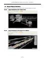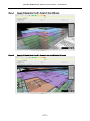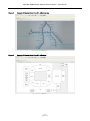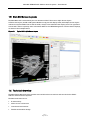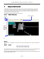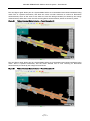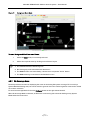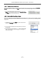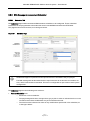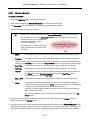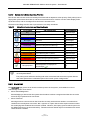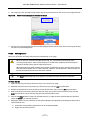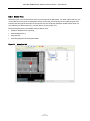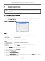
1
IP enabled long-line PA and Voice Alarm control User Manual ASL Document Ref.: Users Manual MCS Generic Issue: 1 MCS Mini iVENCS Public Address Control System – User Manual Copyright © 2010 Application Solutions (Safety and Security) Limited Application Solutions (Safety and Security) Limited Unit 17 Cliffe Industrial Estate Lewes - East Sussex BN8 6JL - UK Tel: +44(0)1273 405411 Fax: +44(0)1273 405415 www.asl-control.co.uk All rights reserved. Information contained in this document is believed to be accurate, however no representation or warranty is given and Application Solutions (Safety and Security) Limited assumes no liability with respect to the accuracy of such information. Issue 1 Page 2 of 129 MCS Mini iVENCS Public Address Control System – User Manual Contents 1 .... Introduction to the MCS Mini Control System ......................................................................................... 10 1.1 ......... Description ............................................................................................................................... 10 1.2 ......... System Model GUI .................................................................................................................... 13 1.2.1 ...... Example 3D System Model Views ..................................................................................... 14 1.2.2 ...... Example 2D System Model Views ..................................................................................... 16 1.3 ......... System Model Modes ............................................................................................................... 18 1.4 ......... System Model Data Overlays .................................................................................................... 18 1.5 ......... Main GUI Screen Layouts ......................................................................................................... 19 1.6 ......... Technical Overview .................................................................................................................. 19 1.6.1 ...... IP Connectivity .................................................................................................................. 20 1.6.2 ...... Client-Server Architecture ............................................................................................... 20 1.6.3 ...... Linux Based Environment ................................................................................................ 20 1.6.4 ...... Flexible and Modular Design ............................................................................................ 20 1.6.5 ...... Local and Remote Operation ............................................................................................ 21 1.6.6 ...... High Reliability and Performance .................................................................................... 21 1.6.7 ...... Security ............................................................................................................................. 21 2 .... Introduction to System Operation ........................................................................................................... 22 2.1 ......... Mouse and Keyboard ................................................................................................................ 22 2.2 ......... User Log Ins and Access Rights ............................................................................................... 23 2.3 ......... To Start the MCS Application ................................................................................................... 24 2.4 ......... The MCS Startup Screen .......................................................................................................... 24 2.5 ......... Logging in to the MCS............................................................................................................... 25 2.6 ......... To Log Off of the MCS ............................................................................................................... 26 2.7 ......... Closing the MCS ....................................................................................................................... 26 3 .... Using the MCS Main GUI .......................................................................................................................... 27 3.1 ......... Fullscreen and Split-Screen Views .......................................................................................... 29 3.2 ......... Built-in Help Functions ............................................................................................................ 31 4 .... MCS GUI Left Side Display Pane – The System Model ............................................................................ 32 4.1 ......... Introduction to the System Model ............................................................................................ 32 4.1.1 ...... 3D System Models ............................................................................................................ 32 4.1.2 ...... 2D System Models ............................................................................................................ 33 4.2 ......... Items Shown in the System Model ........................................................................................... 35 4.2.1 ...... System Model Mouse Control Functions .......................................................................... 36 4.2.2 ...... 3D System Model Levels................................................................................................... 37 4.2.3 ...... Home View ........................................................................................................................ 39 4.2.4 ...... Equipment Status Flags ................................................................................................... 39 4.2.4.1 ... Zoom to Status Flag .................................................................................................. 41 4.2.5 ...... Equipment Information Box ............................................................................................. 41 4.2.6 ...... System Model ‘Picture in Picture’ (PIP) Display............................................................... 42 4.2.7 ...... Selecting and De-Selecting Icons and PA Zones .............................................................. 44 4.2.7.1 ... Icon Controls ............................................................................................................. 44 4.2.7.1.1 Selecting and Deselecting an Icon or Multiple Icons ..................................... 44 4.2.7.1.2 Icon Pop-Up Context Menus ........................................................................... 45 4.2.7.2 ... Select Rectangle ....................................................................................................... 46 4.2.7.3 ... Search Facility .......................................................................................................... 47 4.2.7.4 ... Other Selection Methods .......................................................................................... 47 4.3 ......... Main System Model GUI............................................................................................................ 48 4.3.1 ...... System Model Mode Select Buttons ................................................................................. 48 4.3.2 ...... Select Mode ...................................................................................................................... 48 4.3.3 ...... PA Mode ............................................................................................................................ 48 Issue 1 Page 3 of 129 MCS Mini iVENCS Public Address Control System – User Manual 4.3.3.1 ... Public Address Page Elements................................................................................. 49 4.3.3.2 ... Priority Scheme and DVA Message Queue ............................................................... 51 4.3.3.3 ... PA Zone Broadcast Status Indication........................................................................ 52 4.3.3.3.1 PA Zone Broadcast Status Indication Colour Key........................................... 53 4.3.3.3.2 Examples of the PA Zone Broadcast Status Indication .................................. 53 4.3.3.4 ... Chimes used for PA Broadcasts ............................................................................... 59 4.3.3.5 ... PA Zone Selection ..................................................................................................... 60 4.3.3.5.1 Selection of a PA Zone by Clicking within the Zone Area ............................... 60 4.3.3.5.2 Zone Group Select Buttons ............................................................................. 61 4.3.3.5.3 Custom Zone Group Select Buttons ............................................................... 62 4.3.3.6 ... Live Microphone Announcements ............................................................................ 64 4.3.3.6.1 Microphone Level (VU) Meter ......................................................................... 66 4.3.3.7 ... DVA Message Announcements ................................................................................. 66 4.3.3.7.1 Text-to-Speech ............................................................................................... 66 4.3.3.7.2 Making Recorded DVA Message or Quick Text-to-Speech Announcements 67 4.3.3.7.3 Making Emergency DVA Announcements...................................................... 69 4.3.4 ...... Listen-In Mode .................................................................................................................. 70 4.3.5 ...... Broadcast Mute Mode ....................................................................................................... 72 4.3.5.1 ... Broadcast Mute Zone Status Colours ....................................................................... 72 4.3.6 ...... Background Music Mode .................................................................................................. 73 4.3.6.1 ... Background Music Status Colours ........................................................................... 73 4.3.7 ...... PA Coverage Mode ............................................................................................................ 74 4.4 ......... System Model GUI Control Bars ............................................................................................... 75 4.4.1 ...... System Model Control Button .......................................................................................... 75 4.4.2 ...... Navigation Control Bar ..................................................................................................... 76 4.4.3 ...... Show/Hide Objects Control Bar ........................................................................................ 77 4.4.3.1 ... To Show or Hide the Picture in Picture Image .......................................................... 77 4.4.3.2 ... To Show or Hide all Status Flags .............................................................................. 78 4.4.3.3 ... Selecting Which Status Flags to Display .................................................................. 78 4.4.3.4 ... System Model Overlays............................................................................................. 79 4.4.3.4.1 PA Zone Overlay.............................................................................................. 79 4.4.3.4.2 VA Zone Overlay .............................................................................................. 79 4.4.3.4.3 Detection Zone Overlay................................................................................... 79 5 .... MCS GUI Right Side Display Pane ............................................................................................................ 80 5.1 ......... System Model ‘Fullscreen’ or ‘Split-Screen’ Selection ........................................................... 80 5.2 ......... Right Side Display Pane Mode Buttons .................................................................................... 80 5.3 ......... Right Side Display Pane Functions........................................................................................... 81 5.3.1 ...... Right Side Display Pane Modes ........................................................................................ 81 5.3.2 ...... PIN Confirmation Dialogue ............................................................................................... 82 5.4 ......... Right Side Display Pane Formats ............................................................................................. 83 5.4.1 ...... Table Views ....................................................................................................................... 83 5.4.1.1 ... Sorting Table Views .................................................................................................. 83 5.4.1.2 ... Column Width............................................................................................................ 83 5.4.1.3 ... Saving Table Settings................................................................................................ 83 5.5 ......... PA Functions in the Right Side Pane ........................................................................................ 84 5.5.1 ...... Zone Overrides Tab - Volume Control .............................................................................. 84 5.5.2 ...... DVA Message Announcement Scheduler ......................................................................... 87 5.5.2.1 ... Scheduler Tab ........................................................................................................... 87 5.5.2.2 ... Enabling and Disabling a Schedule........................................................................... 89 5.5.2.3 ... Creating a New Schedule.......................................................................................... 89 5.5.2.4 ... Changing a Schedule ................................................................................................ 91 5.5.2.5 ... Deleting a Schedule .................................................................................................. 92 5.5.3 ...... DVA Message Management .............................................................................................. 93 5.5.3.1 ... DVA Management Tab ............................................................................................... 93 5.5.3.2 ... Recording a New DVA Message ................................................................................ 94 Issue 1 Page 4 of 129 MCS Mini iVENCS Public Address Control System – User Manual 5.5.3.3 ... Creating a New Saved Text-to-Speech Message ...................................................... 95 5.5.3.4 ... Previewing a New Recording or Text-to-Speech Message ...................................... 96 5.5.3.5 ... Saving a Recording or a Text-to-Speech Message ................................................... 97 5.5.3.6 ... Renaming a DVA Message from the Message List ................................................... 98 5.5.3.7 ... Previewing a DVA Message from the Message List.................................................. 99 5.5.3.8 ... Deleting a DVA Message from the Message List .................................................... 100 5.5.3.9 ... Updating DVA Messages across the PA Network ................................................... 101 5.6 ......... Alarm Reporting and the Right Side Pane ............................................................................. 101 5.6.1 ...... System Alarm Status GUIs ............................................................................................. 101 5.6.1.1 ... Alarm Summary ...................................................................................................... 101 5.6.1.2 ... System Alarm Status Levels ................................................................................... 102 5.6.1.3 ... System Alarm Status Reporting Priorities ............................................................. 103 5.6.2 ...... Alarm List ....................................................................................................................... 103 5.6.2.1 ... Acknowledging Alarms ........................................................................................... 105 5.6.2.2 ... Unacknowledging Alarms ....................................................................................... 106 5.6.2.3 ... Clearing Alarms ...................................................................................................... 107 5.6.2.4 ... Locating the Equipment in the System Model ........................................................ 108 5.6.3 ...... Alarm Event History ....................................................................................................... 109 5.6.3.1 ... Alarm Event History Fields and Buttons ................................................................ 109 5.6.4 ...... Status Tree ..................................................................................................................... 111 5.6.4.1 ... To View the Status Tree: ......................................................................................... 113 5.6.4.2 ... Locating Equipment in the System Model from the Status Tree ............................ 114 5.6.4.3 ... Locating the Status Tree Node from the System Model ......................................... 114 6 .... System Maintenance Functions............................................................................................................. 115 6.1 ......... Disabling and Enabling Alarm Reporting ............................................................................... 115 6.2 ......... Routine Maintenance.............................................................................................................. 116 7 .... Print Screen Functionality ..................................................................................................................... 117 8 .... System Administration .......................................................................................................................... 119 8.1 ......... Changing a User’s Password ................................................................................................. 119 8.2 ......... Configuring Users and User Permissions.............................................................................. 120 8.3 ......... Configuring Icons and PA Areas............................................................................................. 120 8.4 ......... Configuring System Alarm Priority Levels and Descriptions ................................................ 120 8.5 ......... Overall System and System Model Configuration.................................................................. 120 9 .... Faultfinding............................................................................................................................................ 121 9.1 ......... Microphone Analogue to USB Converter Faults .................................................................... 121 10 .. Safety and Precautions .......................................................................................................................... 122 10.1 ....... Environmental ........................................................................................................................ 122 10.2 ....... Electrical Safety ..................................................................................................................... 122 10.3 ....... Unpacking and Handling ........................................................................................................ 122 10.4 ....... Packing for Return for Repair ................................................................................................ 122 11 .. Abbreviations ......................................................................................................................................... 123 12 .. Index 124 Service and Warranty .................................................................................................................................. 127 Issue 1 Page 5 of 129 MCS Mini iVENCS Public Address Control System – User Manual Figures Figure 1 Figure 2 Figure 3 Figure 4 Figure 5 Figure 6 Figure 7 Figure 8 Figure 9 Figure 10 Figure 11 Figure 12 Figure 13 Figure 14 Figure 15 Figure 16 Figure 17 Figure 18 Figure 19 Figure 20 Figure 21 Figure 22 Figure 23 Figure 24 Figure 25 Figure 26 Figure 27 Figure 28 Figure 29 Figure 30 Figure 31 Figure 32 Figure 33 Figure 34 Figure 35 Figure 36 Figure 37 Figure 38 Figure 39 Figure 40 Figure 41 Figure 42 Figure 43 Figure 44 Figure 45 Figure 46 Figure 47 Figure 48 Figure 49 Figure 50 Figure 51 Application Diagram – Connection to VIPET, iPA400, and iPAM400 via an IP Network (Example)12 Example 3D System Model View #1 – View of a 3D Model ............................................................ 14 Example 3D System Model View #2 – Zoomed in view of a 3D Model........................................... 14 Example 3D System Model View #3 – View of a 3D Model of 2D Levels ....................................... 15 Example 3D System Model View #4 – Zoomed in view of a 3D Model of 2D Levels ...................... 15 Example 3D System Model View #5 – Zoomed in view on a 3D Level ........................................... 16 Example 2D System Model View #1 – A Railway Line ................................................................... 16 Example 2D System Model View #2 – A Railway Line ................................................................... 17 Example 2D System Model View #3 – A Stadium .......................................................................... 17 Typical GUI in Split-Screen layout ......................................................................................... 19 The MCS Startup Screen ........................................................................................................ 24 MCS Log In Dialog .................................................................................................................. 25 Warning – Login failed ........................................................................................................... 25 Log Off Confirmation Dialog .................................................................................................. 26 Exit to Desktop Confirmation Dialog ..................................................................................... 26 MCS Main GUI Screen Areas .................................................................................................. 27 Menu bar ................................................................................................................................ 27 Menu bar Items and Lists ...................................................................................................... 28 Toolbar ................................................................................................................................... 28 Status Line ............................................................................................................................. 29 System Model – Fullscreen ................................................................................................... 29 System Model – Split-Screen ................................................................................................ 30 Help Menu .............................................................................................................................. 31 Example 3D System Model Home View ................................................................................. 32 Example 3D System Model Single Level View ....................................................................... 33 Example 2D System Model Home View #1 – A Railway Line................................................. 34 Example 2D System Model Home View #2 – A Stadium ........................................................ 34 Example 2D System Model Zoomed In View .......................................................................... 35 System Model Level Select Button Nomenclature #1 .......................................................... 38 System Model Level Select Button Nomenclature #2 .......................................................... 38 System Model Level Select Button Nomenclature #3 .......................................................... 39 Equipment Status Flags in a 3D System Model #1 ................................................................ 40 Equipment Status Flags in a 3D System Model #2 ................................................................ 40 Equipment Status Flags in a 2D System Model ..................................................................... 41 Equipment Information Box................................................................................................... 42 Picture In Picture (PIP) Display ............................................................................................. 42 Loudspeaker Icon Selected ................................................................................................... 44 Typical Pop-Up Menu ............................................................................................................. 45 Select Rectangle Function ..................................................................................................... 46 Search Dialog Example.......................................................................................................... 47 System Model Mode Select Buttons ...................................................................................... 48 A 3D System Model in PA Mode ............................................................................................. 50 A 2D System Model in PA Mode ............................................................................................. 50 Location of the Colour Key Toolbar Button ........................................................................... 53 PA Zone Broadcast Indication Colour Key ............................................................................. 53 PA Zone Broadcast Status Indication – 2D Model showing various broadcasts ................... 54 PA Zone Broadcast Status Indication – No Broadcast ........................................................... 54 PA Zone Broadcast Status Indication – MCS Workstation Live Microphone Broadcast........ 55 PA Zone Broadcast Status Indication – General Overridable Broadcast .............................. 55 PA Zone Broadcast Status Indication – General Non-Overridable Broadcast ...................... 56 PA Zone Broadcast Status Indication – Phased Evacuation #1 ............................................. 56 Issue 1 Page 6 of 129 MCS Mini iVENCS Public Address Control System – User Manual Figure 52 PA Zone Broadcast Status Indication – Phased Evacuation #2 ............................................. 57 Figure 53 PA Zone Broadcast Status Indication – Phased Evacuation #3 ............................................. 57 Figure 54 PA Zone Broadcast Status Indication – Fire Microphone broadcast and Automated Evacuation 58 Figure 55 Selected PA Zones in a 3D System Model ............................................................................. 60 Figure 56 Selected PA Zones in a 2D System Model ............................................................................. 60 Figure 57 Zone Group Select Buttons .................................................................................................... 61 Figure 58 Zone Group Select Buttons .................................................................................................... 62 Figure 59 Custom Zone Button Dialog ................................................................................................... 63 Figure 60 Confirm Overwrite Dialog ...................................................................................................... 63 Figure 61 Custom Zone Button Dialog ................................................................................................... 63 Figure 62 Custom Zone Button Overwrite Confirmation Dialog ............................................................ 64 Figure 63 Custom Zone Button Cleared Confirmation Dialog ............................................................... 64 Figure 64 The PTT Button ...................................................................................................................... 65 Figure 65 Microphone Level (VU) Meter ................................................................................................ 66 Figure 66 The Play DVA Button .............................................................................................................. 67 Figure 67 Dialog: Selecting a Recorded DVA Message or Entering a Text-to-Speech Message .......... 68 Figure 68 The Emergency DVA Button ................................................................................................... 69 Figure 69 Listen In Mode ....................................................................................................................... 71 Figure 70 Broadcast Mute Mode ............................................................................................................ 72 Figure 71 Background Music Mode ....................................................................................................... 74 Figure 72 Navigation Toolbar................................................................................................................. 76 Figure 73 Show/Hide Objects Toolbar showing the Zone Overlays Drop-Down Menu .......................... 79 Figure 74 Right Side Display Pane Mode Buttons.................................................................................. 80 Figure 75 Split-Screen View with Scheduler Pane Displayed ............................................................... 81 Figure 76 Confirm PIN caption Dialog ................................................................................................... 82 Figure 77 Zone Overrides tab................................................................................................................. 84 Figure 78 Overriding the Volume Level in a PA Zone ............................................................................ 85 Figure 79 An Uncommitted Zone Overrides Volume Level Change....................................................... 86 Figure 80 Scheduler Page ...................................................................................................................... 87 Figure 81 Current Schedule Modified and not Committed Warning ..................................................... 88 Figure 82 New Schedule Modified and Committed Dialogue ................................................................ 88 Figure 83 Selected Schedule Details ..................................................................................................... 88 Figure 84 Delete Schedule Dialog.......................................................................................................... 92 Figure 85 DVA Management Page ......................................................................................................... 93 Figure 86 New DVA Buttons ................................................................................................................... 94 Figure 87 Recording Progress Indication .............................................................................................. 94 Figure 88 New DVA Buttons ................................................................................................................... 95 Figure 89 Text To Speech DVA Entry..................................................................................................... 95 Figure 90 TTS Preview ........................................................................................................................... 95 Figure 91 New DVA Buttons ................................................................................................................... 96 Figure 92 TTS Preview ........................................................................................................................... 96 Figure 93 New DVA Buttons ................................................................................................................... 97 Figure 94 DVA Recording Saving Dialogue ............................................................................................ 97 Figure 95 DVA Management Display ...................................................................................................... 98 Figure 96 Rename DVA Dialogue ........................................................................................................... 98 Figure 97 DVA Management Display ...................................................................................................... 99 Figure 98 DVA Previewing...................................................................................................................... 99 Figure 99 DVA Management Display .................................................................................................... 100 Figure 100 DVA Deletion Confirmation Dialogue ................................................................................... 100 Figure 101 Unable to Delete DVA Dialogue ........................................................................................... 100 Figure 102 Alarm Summary................................................................................................................... 101 Figure 103 Alarm List Page ................................................................................................................... 104 Figure 104 Alarm Acknowledgement from the Alarm List ................................................................... 105 Figure 105 Alarm Acknowledgement from a System Model Pop-Up Menu ......................................... 106 Issue 1 Page 7 of 129 MCS Mini iVENCS Public Address Control System – User Manual Figure 106 Figure 107 Figure 108 Figure 109 Figure 110 Figure 111 Figure 112 Figure 113 Figure 114 Figure 115 Figure 116 Figure 117 Figure 118 Figure 119 Figure 120 Figure 121 Alarm Unacknowledgement from the Alarm List .............................................................. 107 Alarm Clearing from the Alarm List .................................................................................... 108 Alarm Clearing from a System Model Pop-Up Menu .......................................................... 108 Alarm Event History Page (part) .......................................................................................... 109 System Alarm Status – Alarm Event History Date Range and Rolling Period Filter Dialogue 110 Status Tree Tab .................................................................................................................... 111 Status Tree Close Up ........................................................................................................... 112 Status Tree Details Example ............................................................................................... 113 Zoom to Equipment Location from the Status Tree ............................................................ 114 Zoom to Equipment in the Status Tree from a System Model Pop-Up Menu ...................... 114 Alarm Reporting Disabled Example .................................................................................... 115 Disabling Alarms from a System Model Pop-Up Menu ....................................................... 116 Entering a Reason for Disabling Alarms from an Item ....................................................... 116 Ksnapshot Dialog ................................................................................................................. 117 KSnapshot Print Dialog........................................................................................................ 118 Change Password Dialog ..................................................................................................... 119 Issue 1 Page 8 of 129 MCS Mini iVENCS Public Address Control System – User Manual Tables Table 1 Table 2 Table 3 Table 4 Table 5 Table 6 Table 7 Table 8 Table 9 Table 10 Default Usernames and Passwords .............................................................................................. 23 Mouse Functions ........................................................................................................................... 36 Equipment Status Flags ................................................................................................................ 39 PA Zone Status Colours ................................................................................................................. 52 Typical Chimes Functionality ........................................................................................................ 59 Listen In Mode Zone Status Colours ............................................................................................. 70 Broadcast Mute Mode Zone Status Colours .................................................................................. 72 Background Music Mode Zone Status Colours ............................................................................. 73 Alarm Status Levels and Typical Operator Actions..................................................................... 102 Alarm Status Levels, Icons, and Reporting Colours............................................................ 103 Issue 1 Page 9 of 129 MCS Mini iVENCS Public Address Control System – User Manual 1 Introduction to the MCS Mini Control System This User Manual provides an overview of the MCS system and guidance on the PA Workstation’s operation. The MCS documentation comprises: • MCS Mini iVENCS Quick Guide • This MCS Mini iVENCS User Manual • System-specific documentation (if appropriate) • MCS Mini iVENCS Maintenance Manual Additional reference documentation for the equipment supplied by Application Solutions (Safety and Security) Limited is available for downloading from the website: www.asl-control.co.uk 1.1 Description The MCS (Mini Control System) is a PC-based control system, based on the same core functionality as the class leading ASL iVENCS Site Control System (SCS). The MCS takes the core functions of the full iVENCS system, and uses these functions in a simplified manner to provide powerful Public Address (PA) and system monitoring functions, while having a simple setup procedure. The MCS incorporates a Digital Voice Announcer (DVA), which enables scheduled PA announcements to be made from messages stored within the PC itself, or elsewhere on an IP network. It can also operate as a paging microphone in which the physical microphone buttons and status indicators are implemented on the display GUI. The MCS can also provide background music routing and control. If desired, the MCS can be fitted with a Text-to-Speech converter 1 as well as, or instead of, DVA message recordings. PA announcements can be made using fixed pre-recorded DVA messages, user recorded messages, Text-to-Speech converted text messages, and fragmented messages which are assembled into complete messages at broadcast time. As well as immediate broadcast functions, DVAs can also be scheduled to be automatically broadcast at intervals, and new DVA and Text-to-Speech messages can also be recorded by the user. Messages can also be broadcast automatically under control of a Customer Information System (CIS), and audio messages can be synchronised with visual information shown on Visual Display Units that are also controlled by the MCS system. A simple, intuitive user interface enables easy and quick operation of the MCS. The PA display graphics are normally customised to show the site plan, with the physical layout of the zones covered by the PA system shown on the screen. The area representing each zone then acts as a ‘zone select’ button, with zone selection and announcement status being shown by different colours. Alternatively the display graphics can be formatted as a set of traditional ‘zone select’ buttons if required. Fault reports from all VIPA systems in the network are shown by the MCS on the PA display graphics using various representative symbols. A system alarm summary is shown at the top of every screen, while traditional list-based displays can provide details of the active alarms and the alarm history. A hierarchical tree view shows alarm status down to particular equipment within each system area. Each alarm is assigned a priority to warn users of severe alarms while still reporting minor alarms. An MCS can also report alarms from third-party equipment. This requires the third-party equipment’s contact alarm or status outputs to be connected to contact inputs on an ASL BMB01 Remote I/O Unit which is then connected to a VIPA system. 1 MCS uses Acapela speech technologies licensed from the Acapela Group. The ASL text-to-speech converter uses Acapela text-to-speech processing software. Issue 1 Page 10 of 129 MCS Mini iVENCS Public Address Control System – User Manual The MCS Mini Control System comprises a client PC with LCD monitor, a keyboard and a mouse, and an optional server PC 2. The server functions can be hosted in the client PC if required, but if there are multiple clients then it is normally preferred to have a separate server. Each client PC can be provided with one of several different types of flexible gooseneck microphone, for live microphone paging and DVA recording functions. If alternative functionality or interfaces to other systems are required, please consult ASL. Modular system design enables only the required functions to be provided at each workstation, and individual user or group, logons enable the required functions to be facilitated according to each user’s specific requirements. The MCS can be connected via an IP network to ASL VIPA systems such as the VIPET IP Audio Controller, the iPA400 Intelligent 400W PA Amplifier Mainframe, and the iPAM400 Intelligent 400W PA Amplifier Mainframe with Loudspeaker Line Monitoring. This provides multiple broadcast channels, and depending on the system configuration, scheduled broadcasts may be able to continue even with a network failure or with the MCS turned off. If the wide range of functions provided by the MCS system is not sufficient for the control and monitoring requirements of an installation, then all of these functions are also available in the full iVENCS control system, as well as sophisticated integration with almost any possible other Sub-system. 2 The number of client PCs is only limited by the server’s available memory and CPU. The standard server can support up to 50 client PCs. Issue 1 Page 11 of 129 MCS Mini iVENCS Public Address Control System – User Manual Figure 1 Application Diagram – Connection to VIPET, iPA400, and iPAM400 via an IP Network (Example) Issue 1 Page 12 of 129 MCS Mini iVENCS Public Address Control System – User Manual 1.2 System Model GUI In this Manual the term ‘System Model’ refers to the Graphical User Interface (GUI) view of the system or site being controlled. The System Model may be a two-dimensional or three-dimensional (2D or 3D) representation, or a combination of 2D and 3D, depending on the requirements of the particular installation. Typical examples of these GUI interfaces would be a 3D Model of a building, or a 2D view of a railway line map. The System Model is displayed in the Main GUI at all times when the Workstation application is running, with the System Model’s ‘Home’ position showing the overall view of the site or system. 3D System Models With 3D System Models the overall model is normally composed of a number of individual stacked floor levels, with ‘drill down’ to the individual floor levels. Tilt controls are provided to move the 3D model from plan view towards elevation, and Pan, Zoom and Rotate controls are also provided, facilitating extensive manipulations of the model views. Inter-level transitions such as lifts, travelators, and stairs are shown dropping down from or rising up from the site level in the appropriate locations. 2D System Models With 2D System Models the view normally has a fixed orientation, with no Tilt or Rotate controls. There may be Zoom and Pan functions provided however, so that individual sections of the 2D model can be zoomed into for a closer view, and so that the display can be moved around within the extents of the overall System Model limits, for instance to zoom into the location of an alarm in the System Model. There may also be a ‘drill down’ to more detailed views such as to individual station views from a 2D railway line top level view. Status Reporting on the System Models Sub-system devices are represented by Icons on the System Model, with Status Flags appearing above the equipment Icons in the System Model as necessary to indicate the status of the equipment. In the case of System Models such as railway line maps the Status Flags may appear next to each station to indicate the overall status of the equipment at the station. In the case of System Models such as buildings the Status Flags may appear next to peripheral equipment Icons to indicate the status of each item of equipment, while Flags may appear next to equipment rack Icons to indicate the overall status of the equipment located in that rack. A help text is displayed when the mouse pointer is hovered over an Icon. Each Icon on the System Model may be selected and a Pop-Up menu displayed of functions that can be carried out on that item. The menu content depends on each device and may for instance include functions to: • Disable or Enable alarm reporting • Acknowledge alarms • Clear alarms System Model Access Rights All users have access to the various System Model views. However, the ability of individual users to access tabs and functions such as actions on the main and Pop-Up menus is controlled by the access rights which are defined in their user Log On profile. Issue 1 Page 13 of 129 MCS Mini iVENCS Public Address Control System – User Manual 1.2.1 Example 3D System Model Views Some examples of various different views of different types of 3D System Model are as below: Figure 2 Example 3D System Model View #1 – View of a 3D Model Figure 3 Example 3D System Model View #2 – Zoomed in view of a 3D Model Issue 1 Page 14 of 129 MCS Mini iVENCS Public Address Control System – User Manual Figure 4 Example 3D System Model View #3 – View of a 3D Model of 2D Levels Figure 5 Example 3D System Model View #4 – Zoomed in view of a 3D Model of 2D Levels Issue 1 Page 15 of 129 MCS Mini iVENCS Public Address Control System – User Manual Figure 6 Example 3D System Model View #5 – Zoomed in view on a 3D Level 1.2.2 Example 2D System Model Views Some examples of various different views of different types of 2D System Model are as below: Figure 7 Example 2D System Model View #1 – A Railway Line Issue 1 Page 16 of 129 MCS Mini iVENCS Public Address Control System – User Manual Figure 8 Example 2D System Model View #2 – A Railway Line Figure 9 Example 2D System Model View #3 – A Stadium Issue 1 Page 17 of 129 MCS Mini iVENCS Public Address Control System – User Manual 1.3 System Model Modes The System Model GUI has a number of distinct and mutually exclusive control modes, with button selection between them made using a line of ‘radio button’ toggle action buttons which are located above the System Model’s GUI display. The possible System Model modes are as follows: • • • • • • Select Mode o System alarm monitoring mode PA Mode o For making PA announcements Listen In Mode o For selecting an individual zone to listen in to (monitoring broadcasts to that zone) Broadcast Mute Mode o For controlling the muting of PA zones for defined priorities of broadcast Background Music Mode o For controlling the routing of a central background music source, or other external audio feed PA Coverage Mode o Shows the total PA Zone coverage area. 1.4 System Model Data Overlays Additional data can be selected to be overlaid on top of the System Model for circumstances when this information is required, with the information being accessed via the ‘Show/Hide Objects’ function. These image overlays can be used to show any required data for the individual installation’s requirements, with the default overlays being as follows: • • • PA Zone Overlay o For displaying all the PA zone areas VA Zone Overlay o For displaying all the VA (Voice Alarm) zone areas Fire Detection Zone Overlay o For displaying all the Fire detection areas. Issue 1 Page 18 of 129 MCS Mini iVENCS Public Address Control System – User Manual 1.5 Main GUI Screen Layouts The MCS Main GUI is selectable by the user between either Fullscreen or Split-Screen layout. In Fullscreen layout, the 2D or 3D System Models occupy the full display width, while Split-Screen layout reduces the System Model size to half the width, always in the left half of the display area. The right hand screen half is then occupied by other information GUIs such as DVA Management or Alarm Status displays, as shown in the example below: Figure 10 Typical GUI in Split-Screen layout 1.6 Technical Overview The MCS Public Address System provides users with functions to monitor and control the site Public Address and Voice Alarm Systems. The MCS main features are: • IP Connectivity • Client-server architecture • Linux based environment • Flexible and modular design Issue 1 Page 19 of 129 MCS Mini iVENCS Public Address Control System – User Manual • Local and remote operation • High reliability and performance • Security 1.6.1 IP Connectivity The MCS connects to the ASL VIPA PA systems via an IP Network. This can take many physical formats, but is commonly implemented as a 100 Mbit/s Ethernet link over CAT5 cable. The PA/VA system itself can also take many formats, with typical items in the network being the VIPET IP Audio Controller and the iPAM400 Intelligent Amplifier Mainframe. Transmission of audio between the MCS and the VIPA units in the system uses the PMC (Portable Media Carrier) protocol. 3 This is capable of multicast operation, where there is one source and multiple simultaneous destinations, and this implementation minimises the IP Bandwidth requirement. The MCS and VIPA units can however be configured for unicast operation, with one source to only one destination, on networks that do not support multicast. In multicast operation a star topology network with router and active switches that support layer 2 (MACbased) multicast is recommended for maximum bandwidth savings. A private local network is recommended for secured data transfer. If required, connections across a shared or open network should use a dedicated VPN (Virtual Private Network),’ in order to secure all data transfer. 1.6.2 Client-Server Architecture The workstations provide all control functions and displays of the operating state of the controlled Subsystem by means of Graphical User Interfaces. The MCS Server implements the necessary interfaces with Sub-systems, which in this case comprise the site’s PAVA system. 1.6.3 Linux Based Environment The operating platform for the server and workstations is SUSE Linux, Enterprise Version. 1.6.4 Flexible and Modular Design The MCS software has a modular distributed architecture which provides flexible and powerful PAVA control functions. If the MCS is operated as part of a full iVENCS control system which interfaces to other Sub-systems (e.g. Telephone, CCTV, Building Management System, etc.), then there is a Sub-system handler module for each Sub-system. These communicate with the Sub-system hardware and provide status data and control functions to the rest of the control system. All inter-module communication uses the ASL JCOP and JPC technology. New modules can be developed for a particular deployment to interface with other Sub-systems. 3 Standard IPv4 UDP multicast with IGMPv3, which is compatible with all modern desktop and server operating systems, such as Windows, MacOS, Linux, Solaris, AIX, HP/UX, BSD, etc. Issue 1 Page 20 of 129 MCS Mini iVENCS Public Address Control System – User Manual 1.6.5 Local and Remote Operation The MCS system can operate with remote control workstations just as easily as with local workstations. Therefore the provision of backup control centres for a system is easily done using the standard setup. A VPN is the preferred IP interconnection route for remote user Log On. 1.6.6 High Reliability and Performance The MCS software design combined with high specification servers and workstations enables high system performance on almost any form of IP network. The inherent system reliability in the design of the MCS is based on: • Combined event and data-driven design approach Data-driven designs tend to be more reliable than event-driven ones, as they avoid any possibility of an event being missed. Event-driven designs tend to be more efficient in terms of processor usage and more responsive in terms of event detection and propagation. The ASL software architecture (JCOP/JPC) combines both approaches. The JPC status publishing method reacts instantly to changes in state, generating events for maximum responsiveness. It also supports heuristic refresh techniques to ensure that events cannot be missed, while minimising the impact on processor usage. • Dual redundant servers and workstations (with full control system upgrade). 1.6.7 Security Following the launch of the MCS application, the MCS maintains security, and prevents both unauthorised access to the system, and unauthorised operations by legitimate users. This is enforced through a system of users and user groups, where a user’s permissions are determined by those configured for the username, and any group or groups to which the user belongs. Issue 1 Page 21 of 129 MCS Mini iVENCS Public Address Control System – User Manual 2 Introduction to System Operation 2.1 Mouse and Keyboard The MCS workstation is primarily operated using a mouse. Apart from when it is used as an alternative to the mouse (see below), the alphanumeric keyboard is only needed for entering customer-specific text in certain windows. The keyboard set-up is the international one. Both the left and the right mouse buttons are used when working with the user interface. If you have a three-button mouse, the buttons must be set accordingly; the third (middle) button is not used, except as a scroll wheel. The left mouse button is used the same way as in Linux and may be used for example to: • Select a PA zone in the System Model; • Select a pull-down menu from the top bar of a window; • Select a menu item; • Select a function using the features available in a window (buttons, drop-down menus, contextsensitive Pop-Up menus, etc.); • Confirm or cancel an action. Throughout this document, the instruction ‘click on’ (e.g. a control button or tab) is defined as a momentary pressing of the left mouse button when the screen cursor is positioned over the subject screen item. Where right mouse button operation is required, that will be specifically stated. The right mouse button is used, for example, to access a Pop-Up or context-sensitive menu on either the System Model or on the alarm monitoring pages. As an alternative to using the mouse, you can select menus from the Menu bar using the <Alt>+’underlined letter’ combination of keystrokes. You can select individual menu items from a menu simply by pressing the key combination corresponding to the underlined letter. The rest of this MCS Mini iVENCS Public Address Control System - User Manual refers exclusively to use of the mouse. Issue 1 Page 22 of 129 MCS Mini iVENCS Public Address Control System – User Manual 2.2 User Log Ins and Access Rights Access Rights The system configuration provides for different users to have different access rights, with the access rights being defined by permissions configured for any user groups to which the user belongs. Additionally, individual user Log Ins can be assigned different access facilities to other users nominally in the same user group or groups. While all users have access to the available views in the System Model each user’s access rights determines the MCS resources such as administrative functions, Sub-system control functions, and alarm handling functions that are available to them. User Groups There can be any number of different user groups, each having access to all or any of the functions available in the MCS system. In a typical installation however there may be three discrete user groups, each giving capabilities as follows : A) System Administrator: a. Operational functions b. Access to the Alarm reporting screens c. Access to the ‘Design Mode’ for editing of Icons, etc in the model. (Described in the MCS Maintenance Manual.) B) Local Managers and Maintenance Staff: a. Operational functions b. Access to the Alarm reporting screens C) Operators: a. Operational functions. Default Usernames and Passwords The system configuration can specify any number of Usernames as required. On initial system supply, the available user Log Ins are normally provided with default Usernames and passwords, as below : Table 1 Default Usernames and Passwords Title System Administrator Local Managers and Maintenance Staff Operators Username Admin Manager Operator Password admin manager operator Issue 1 Page 23 of 129 MCS Mini iVENCS Public Address Control System – User Manual 2.3 To Start the MCS Application On powering up a MCS workstation, the start-up scripts automatically Log In to the workstation and server operating system platforms, and launch the MCS software application. The MCS application normally runs all the time the Workstation is turned on. Only users with permission to exit the MCS can close the application. If however the MCS application has been closed then it needs to be re-started from the desktop, as follows: 1. Click on the iVENCS Icon on the desktop ! (once only). Do not double-click the iVENCS Icon - this could launch two instances of the MCS application, and ultimately cause system misbehaviour. Although the MCS system traps for multiple copies being run at one time, and will normally prevent the software from being started if a copy is already running, if multiple copies are run for any reason, reboot the machine. The MCS will start automatically. 2.4 The MCS Startup Screen Once the MCS application has been started, either directly on power up or from the desktop iVENCS Icon, then the MCS Startup Screen will be shown. This screen displays the Menu bar and Toolbar, plus the Log In dialogue box. The Toolbar displays the Alarm Summary, so that the system’s Alarm List summary can be seen even without a user being Logged In to the system. Figure 11 The MCS Startup Screen Issue 1 Page 24 of 129 MCS Mini iVENCS Public Address Control System – User Manual 2.5 Logging in to the MCS Log In to the MCS as Operator, Maintainer, Administrator, etc according to your role, using the Username and Password that you have been provided with. 1. If the MCS Log In dialog is not displayed, select FileLog On from the Menu bar, or press the (Login) Icon on the Toolbar of the MCS Main GUI. The MCS Log In dialog is displayed: Figure 12 MCS Log In Dialog 2. Enter the Username and Password in the fields in the dialog. 3. Click on the Log In button to proceed with logging in, or click on the Exit button to close the Log In dialog without logging into the system. 4. You will be prompted to change the password if the password has expired. (See Section 8.1, Changing a User’s Password on Page 119). Fields Username The operator’s Username as configured by the system administrator. Password The operator’s password. Buttons Click on this button to Log In to the system. Click on this Exit button to cancel logging in to the system. A warning window will be displayed if an invalid username or password is entered, then see below: Figure 13 Warning – Login failed Issue 1 Page 25 of 129 MCS Mini iVENCS Public Address Control System – User Manual 2.6 To Log Off of the MCS All users can Log Off of the MCS, to return to the Startup screen. 1. Select FileLog Off from the Menu bar or click on the will be displayed; see below: Figure 14 Icon on the Toolbar. A confirmation dialog Log Off Confirmation Dialog 2. Click on the Yes button to log off and return to the Startup screen, or click on No to cancel the operation. 2.7 Closing the MCS The MCS application will normally be running all the time the Workstation is turned on. However, users granted with permission to exit the Workstation can close the application and then access the Operating System, as follows: 1. Select FileExit from the Menu bar of the MCS Main GUI. A confirmation dialog will be displayed; see below: Figure 15 Exit to Desktop Confirmation Dialog 2. Click on the Yes button to exit and close the MCS application, or click on No to cancel the operation. Issue 1 Page 26 of 129 MCS Mini iVENCS Public Address Control System – User Manual 3 Using the MCS Main GUI The MCS Main GUI shows the System Model, the PA Sub-system GUI, the Alarm Displays, and provides access to the overall Workstation functions. When a user Logs In to the MCS then the MCS Main GUI is started and allocated to the screen in Fullscreen mode, or Split-Screen mode, depending on how it was configured the last time the MCS was closed. The MCS Main GUI has the following major screen areas: Figure 16 MCS Main GUI Screen Areas Alarms Summary Toolbar Menu bar System Model and Subsystem Display Area St t Menu bar The Menu bar is configurable as part of the overall system configuration, with a typical configuration as below: Figure 17 Menu bar Each of the Menu bar items has a drop-down list. These lists provide access to various overall Workstation GUI functions. View one of these drop-down lists by clicking on the appropriate Menu bar item. The lists under the Menu bar items are also configurable as part of the overall system configuration, with typical examples being as follows: Issue 1 Page 27 of 129 MCS Mini iVENCS Public Address Control System – User Manual Figure 18 Menu bar Items and Lists Toolbar The Toolbar provides quick access to the most frequently used overall functions. It also provides summary status information. Again, this information is configurable as part of the overall system configuration. From left to right in the following example, these functions are: Figure 19 Toolbar Log In to the system (if Logged Out). Log Out of the system (if Logged In). Fullscreen mode – Toggles between Fullscreen and Split-Screen displays. Help – Opens the MCS Quick Guide. Colour Key – Opens a Dialog Box which shows the PA Zone colours used in the System Model. Search function – Opens the Search Dialog Box. Alarm Total Displays a count of the total number of System Alarms. Alarm Displays a count of the number of System Alarms sorted by priority and acknowledgement Summary states. ! When viewing the Quick Guide do not use any of the functions available in the PDF viewer to browse or edit the MCS application files on the workstation, doing this could cause erratic or incorrect operation of the MCS application, or could even disable it entirely. System Model and Sub-system Display Area This area displays the System Model in either Fullscreen or Split-Screen view. If in Split-Screen view then the System Model is located in the Left Display Pane other information is also shown in the Right Display Pane. Issue 1 Page 28 of 129 MCS Mini iVENCS Public Address Control System – User Manual Status Line The Status Line displays summary status data for the entire MCS workstation. The information provided in the Status Line is: • The Username of the currently Logged In user; • The workstation name; • The Online or Offline status of the MCS workstation 4; • The current date and time. Figure 20 Status Line Currently the Online or Offline status indicator will always read as ‘Online’. 3.1 Fullscreen and Split-Screen Views In Fullscreen layout, the 2D or 3D System Models occupy the full display width as shown below. SplitScreen layout reduces the System Model size to half the width, always in the left half of the display area. The right hand screen half is then occupied by other information GUIs such as DVA Management or Alarm Status displays, as shown in the subsequent Figure: Figure 21 System Model – Fullscreen The Online or Offline status of the MCS workstation relates to whether the system is in Live Operational mode (Online), or the Non-Operational Training mode (Offline). Currently the Training mode is only a function of the full iVENCS Control System and is not available in the MCS system. Therefore this will always read as ‘Online’. 4 Issue 1 Page 29 of 129 MCS Mini iVENCS Public Address Control System – User Manual Figure 22 System Model – Split-Screen To Toggle between displaying the System Model Fullscreen or Split-Screen: Either: 1. Select ViewFullscreen from the Menu bar of the MCS Main GUI to make the MCS Main GUI change between Fullscreen and Split-Screen format. Or: Fullscreen Icon on the Toolbar of the MCS Main GUI to make the MCS Main GUI change 2. Click the between Fullscreen and Split-Screen format. Issue 1 Page 30 of 129 MCS Mini iVENCS Public Address Control System – User Manual 3.2 Built-in Help Functions The MCS GUI provides a number of help functions, including access to this User Manual and to a Quick Guide. To Open the MCS User Manual or Quick Guide from the Help Menu: 1. Click on the Help button in the MCS Main GUI Menu bar. 2. A drop-down list is displayed (see typical example below): Figure 23 Help Menu 3. Click on the reference document that you wish to view, either the User Manual (this document), or the Quick Guide. 4. The PDF document reader application will then start and will display the selected document in front of the GUI. 5. View the document as required and when complete then close the PDF viewer application again. ! When viewing the User Manual or Quick Guide do not use any of the functions available in the PDF viewer to browse or edit the MCS application files on the workstation, doing this could cause erratic or incorrect operation of the MCS application, or could even disable it entirely. The PDF file viewer application window can be resized or dragged across the screen using the mouse if desired. The HelpAbout option gives details of the MCS application. The User’s Quick Guide can also be opened from the Issue 1 Page 31 of 129 Icon on the Toolbar. MCS Mini iVENCS Public Address Control System – User Manual 4 MCS GUI Left Side Display Pane – The System Model 4.1 Introduction to the System Model The System Model is displayed in the MCS Main GUI at all times, either as the full screen in Fullscreen mode, or as the left half of the screen in Split-Screen mode. 4.1.1 3D System Models With a 3D System Model the entire System Model can be viewed as a single item, and can be navigated using the Tilt, Pan, Zoom and Rotate controls to view any part of the Model. This is useful for viewing and associating groups of alarms occurring together on different levels of the Model, for instance on different floors of a building if several floors are affected by the same emergency. 3D System Model Home View A 3D System Model will have a defined Home position where the whole System Model is shown in a reference overall view, including all floors, which are known as ‘levels’ in the MCS. Each Level also has a home view, which is a vertical view straight down on that level, in the same orientation as the home view of the full System Model.. An example of a full System Model’s home view is shown below: Figure 24 Example 3D System Model Home View Each level of the 3D System Model is then individually selectable in order to view or control items on that level. Inter-level transitions such as lifts, travelators, and stairs are shown dropping down from or rising up from the level in the appropriate locations, as in the example below: Issue 1 Page 32 of 129 MCS Mini iVENCS Public Address Control System – User Manual Figure 25 Example 3D System Model Single Level View 4.1.2 2D System Models With 2D System Models the view normally has a fixed orientation, with no Tilt or Rotate controls. There may be Zoom and Pan functions provided however, so that individual sections of the 2D model can be zoomed into for a closer view, and so that the display can be moved around within the extents of the overall System Model limits, for instance to zoom into the location of a alarm in the System Model. There may also be a ‘drill down’ to more detailed views such as to individual station views from a 2D railway line top level view. 2D System Model Home View A 2D System Model will have a defined Home position where the whole System Model is shown in a reference view, and unlike 3D models for the 3D Model this home position will be the normal operational view. Two examples of this are shown below: Issue 1 Page 33 of 129 MCS Mini iVENCS Public Address Control System – User Manual Figure 26 Example 2D System Model Home View #1 – A Railway Line Figure 27 Example 2D System Model Home View #2 – A Stadium If it is desired to zoom into a 2D System Model in order to gain a closer view of an item, then this may also be done, as in the example below: Issue 1 Page 34 of 129 MCS Mini iVENCS Public Address Control System – User Manual Figure 28 Example 2D System Model Zoomed In View 4.2 Items Shown in the System Model The System Model shows all monitored equipment as Icons. For instance, a loudspeaker Icon may be used to represent each PA zone’s amplifier and loudspeaker circuits, and be positioned in the centre of the PA zone on the model, alternatively a fire panel may actually be shown as a fire panel mounted in the appropriate position. Alarm indications, warnings, or selected status reports on each of these items can then be displayed in this view. An alarm or other warning for an item is displayed by the appropriate alarm Flag being shown above the Icon in the model. All the Icons and any associated Flags and all zone overlays are shown on the entire System Model as well as in the individual Level Views. However, the PA Control functions operate only in the individual Level Views. Icons representing the MCS workstations and any server connected to the system will normally also be shown on the System Model, in which case they will also show alarm report Icons in the case of any alarms, unless the nature of the alarm prevents this. Further data on any alarm can be obtained from the alarm displays which can be shown in the right hand pane of the screen. Issue 1 Page 35 of 129 MCS Mini iVENCS Public Address Control System – User Manual 4.2.1 System Model Mouse Control Functions The following Table shows the System Model manipulation functions available using the mouse: Table 2 Mouse Functions Function With <CTRL> Modifier With <SHIFT> Modifier With <CTRL> and <SHIFT> Modifiers Pan Rotate (3D System Models Only) Rubber Band Zoom Select Rectangle Zoom Tilt (3D System Models Only) No Modifiers Single Left Click Select Double Left Click Action Hold and Drag (Left) Scroll Wheel Single Right Click Pop-Up Context Menu Mouse ‘Select’ Operation A single click of the left button on the mouse will select any suitable item that the mouse pointer is over, for any required follow up operation to be carried out on it. Mouse ‘Action’ Operation A double click of the left button on the mouse will select and carry out any appropriate action on any suitable item that the mouse pointer is over, For instance a double click on a position in the PIP display will centre the main System Model display to that location, or a double click on an alarm relating to any given item in the Alarm List will zoom the System Model to the location of that item. Mouse ‘Pan’ Operation Holding the mouse’s left button down while the mouse pointer is over the System Model GUI, and then moving the mouse, will Pan (or drag) the System Model around in the System Model GUI display. Mouse ‘Rotate’ Operation Holding the <CTRL> Key down together with the mouse’s left button while the mouse pointer is over the System Model GUI, and then moving the mouse to the left or right, will Rotate the System Model around the centre of the System Model GUI display. Mouse ‘Rubber Band Zoom’ Operation Holding the <SHIFT> Key down together with the mouse’s left button while the mouse pointer is over the System Model GUI, and then moving the mouse pointer within the System Model GUI will drag out a light blue coloured rectangle on the System Model. Issue 1 Page 36 of 129 MCS Mini iVENCS Public Address Control System – User Manual When the mouse button is released then the System Model GUI display will zoom to show the contents of the dragged rectangle. This function can be used to quickly zoom into a particular area on the System Model. Mouse ‘Select Rectangle’ Operation Holding the <CTRL> and <SHIFT> Keys down together with the mouse’s left button while the mouse pointer is over the System Model GUI, and then moving the mouse pointer within the System Model GUI will drag out a light blue coloured rectangle on the System Model. When the mouse button is released then all of the PA Zones and/or Icons within the dragged rectangle will be selected. This function can be used to quickly select all of the items in a given area of the System Model. Mouse ‘Zoom’ Operation Rotating the mouse’s scroll wheel while the mouse pointer is over the System Model GUI will zoom the view of the System Model in or out around the current centre position of the display. Rotating the scroll wheel ‘forward’ will zoom in, while rotating the scroll wheel ‘backwards’ will zoom out. Mouse ‘Tilt’ Operation Holding the <CTRL> Key down while rotating the mouse’s scroll wheel while the mouse pointer is over the System Model GUI will Tilt the view of the System Model up or down around the current centre position of the display. Rotating the scroll wheel ‘forward’ will Tilt the System Model towards a vertical view down, while rotating the scroll wheel ‘backwards’ will Tilt the System Model towards a horizontal view from the side.. Mouse ‘Select’ Operation A single click of the right button on the mouse will open up the Pop-Up context sensitive menu of any suitable item that the mouse pointer is over, for any required follow up operation to be carried out on it. 4.2.2 3D System Model Levels Each level of a multi-level 3D System Model is selectable as a stand-alone view by clicking on the appropriate Level Select button on the left-hand side of the display area. Typically each System Model level will represent an individual floor level in an entire building which is represented by the whole System Model. Level Select Buttons Each Level Select button has the name of its System Model level and has an appropriate tool tip description. Clicking on one of these buttons will switch the view to the selected level from another System Model level, or from the top view. Note that when changing between levels (z co-ordinate change) the relative position in the new System Model level is not changed (the x and y co-ordinates remain the same). Following are some examples of stand-alone level views and their Level Select Buttons: Issue 1 Page 37 of 129 MCS Mini iVENCS Public Address Control System – User Manual Figure 29 System Model Level Select Button Nomenclature #1 For this example, a site with three levels, a Mezzanine, Ground Floor and Substructure Floor, has the Level Buttons configured as follows: Click on this button to display the mezzanine level System model. Click on this button to display the ground level System model. Click on this button to display the substructure level System model. The System Model level buttons may use any appropriate nomenclature, e.g. for a site with levels 1, 2, 3, etc then these may be labelled as L01, L02, L03, etc, as in the following example: Figure 30 System Model Level Select Button Nomenclature #2 Issue 1 Page 38 of 129 MCS Mini iVENCS Public Address Control System – User Manual A Station with Ticket Hall and Platform Levels may be configured with Level Buttons as shown below: Figure 31 System Model Level Select Button Nomenclature #3 4.2.3 Home View A ‘Home’ button is provided above the Level Select Buttons. Clicking this button once while in a System Model Level view will cancel any view manipulations within that level and will return the display to that level’s home view. Clicking this button while in a System Model Level’s home view will return the display to the whole System Model’s home view, showing all Levels. Thus clicking this button twice from anywhere will return the display to the whole System Model’s home view. i.e. 1. To return to the home position on the current level, click on the Home button 2. To return to the full System Model home view, click the Home button once. again. 4.2.4 Equipment Status Flags Flags are shown above the various equipment Icons in the System Model in order to indicate the overall status of the equipment represented by those Icons. See Section 5.6.1.2, System Alarm Status on Page 102 for details of the various System Status Priorities, and see the following table for the various possible equipment status Flag types: Table 3 Equipment Status Flags Flag System Alarm Status Unknown Information Warning Typical Meaning Unknown Alarm Information Unknown Lowest Maintenance Requirement Reduced Service Reduced Service Alarm Service-Affecting Fault Priority Alarm Priority Life Safety Emergency Issue 1 Page 39 of 129 Highest MCS Mini iVENCS Public Address Control System – User Manual Figure 32 Equipment Status Flags in a 3D System Model #1 Figure 33 Equipment Status Flags in a 3D System Model #2 Issue 1 Page 40 of 129 MCS Mini iVENCS Public Address Control System – User Manual Figure 34 Equipment Status Flags in a 2D System Model In the above examples, Priority Alarm ( 4.2.4.1 ) and Alarm ( ) Flag types are shown. Zoom to Status Flag If a Status Flag is clicked in any of the System Model views, then the System Model GUI will zoom in to the location of that status Flag. If the System Model GUI is a 3D GUI and is originally showing the whole System Model then the GUI will also switch to the view of the Level on which the Flag resides. This provides a quick method of viewing the item related to the status Flag, and its location in the System Model. With 2D System Models this function can be disabled, so that clicking on an alarm flag does not change the display view. This can be beneficial for System Models, such as railway line maps. 4.2.5 Equipment Information Box At the bottom left of the System Model GUI there is a light grey Equipment information, or ‘help text’, box which contains information text regards the last item in the System Model that was selected with the mouse, and also for the current item that the mouse pointer is over. There are four lines of information given in the information box, which are as follows: 1. The top line of text provides the ‘JPC Path’ for the item in the System Model that the mouse pointer is currently over. 2. The next line of text provides the JPC Path of the last item in the System Model that was selected with the mouse. 3. The next line of text provides the Description of the last item in the System Model that was selected with the mouse. 4. The bottom line of text provides the Current overall status of the last item that was selected with the mouse. Issue 1 Page 41 of 129 MCS Mini iVENCS Public Address Control System – User Manual Figure 35 Equipment Information Box 4.2.6 System Model ‘Picture in Picture’ (PIP) Display The System Model GUI has an option to show an overview ‘Picture in Picture’ (PIP) window in the upper left corner of the System Model. This feature provides a high level overview of the whole System Model on the selected Level, indicating the centre of the area being viewed on the main System Model display with a star symbol ( ). Double clicking anywhere on the PIP display will zoom the centre of the main System Model display to this position. A typical PIP overview image and associated main view display is shown below. Figure 36 Picture In Picture (PIP) Display When selected, the PIP is shown at all zoom levels of the main view display and is provided in both Fullscreen and Split-Screen views. See Section 4.4.3, Issue 1 Page 42 of 129 MCS Mini iVENCS Public Address Control System – User Manual Show/Hide Objects Control Bar on Page 77 for details of how to enable and disable the PIP display. Note that as shown in the example above, the orientation of the PIP remains constant as per the System Model’s home position, even when the main System Model view has been rotated. Issue 1 Page 43 of 129 MCS Mini iVENCS Public Address Control System – User Manual 4.2.7 Selecting and De-Selecting Icons and PA Zones 4.2.7.1 Icon Controls When clicking on an Icon, the mouse buttons perform the following operations: • A left button click selects the Icon, and its PA Zone if in an appropriate System Model control mode, • A right button click selects the Icon and invokes its Pop-Up menu. 4.2.7.1.1 Selecting and Deselecting an Icon or Multiple Icons To access user functions associated with the device(s) represented by one or more specific Icons, it is first necessary to select the Icon(s) on the GUI. User functions include Acknowledging and Clearing Alarms, and Enabling or Disabling Alarms. To Select and Deselect an Icon or Multiple Icons carry out the actions as below: 1. Select an Icon by clicking on it. A transparent box enclosing the Icon will appear to indicate that it is selected. The example in the next Figure shows a loudspeaker Icon which has been selected. Figure 37 Loudspeaker Icon Selected Loudspeaker Icons are normally used to represent the PA zone amplification equipment and loudspeaker circuits in their entirety. Therefore a alarm in the loudspeaker circuit wiring or in the associated amplification equipment will raise a Flag against the Loudspeaker Icon. 2. Add other Icons to the selection by clicking each Icon in turn. 3. Deselect an Icon to remove it from the selection by just clicking on it again. 4. To deselect all selected Icons, right click any Icon and select the Deselect Items option from the PopUp menu. See the following section for details: Issue 1 Page 44 of 129 MCS Mini iVENCS Public Address Control System – User Manual 4.2.7.1.2 Icon Pop-Up Context Menus Each Icon on the System Model may be selected and its Pop-Up menu displayed by right clicking on the Icon. The menu content depends on the device being represented by the Icon, and along with many other similar functions this is also restricted by the user’s access level. A typical Pop-Up menu is as below: Figure 38 Typical Pop-Up Menu The following menu options are typically available for each device: Deselect items: Deselects all previously selected Icons Acknowledge: Acknowledges all alarms associated with the device represented by the Icon Clear Alarms: Clears all alarms associated with the device represented by the Icon Enable Alarms: Enables alarm reporting from the device represented by the Icon Disable Alarms: Disables alarm reporting from the device represented by the Icon When multiple Icons are selected, the Pop-Up menu options will be reduced to a subset that is applicable to all of the selected Icons, with any menu items that are only applicable to some of the Icons being removed. Issue 1 Page 45 of 129 MCS Mini iVENCS Public Address Control System – User Manual 4.2.7.2 Select Rectangle Holding the <CTRL> and <SHIFT> Keys down together with the mouse’s left button while the mouse pointer is over the System Model GUI, and then moving the mouse pointer within the System Model GUI will drag out a light blue coloured rectangle on the System Model. When the mouse button is released then all of the PA Zones and/or Icons within the dragged rectangle will be added into the current selection. Figure 39 Select Rectangle Function Issue 1 Page 46 of 129 MCS Mini iVENCS Public Address Control System – User Manual 4.2.7.3 Search Facility A search facility for is available through a Menu bar option, a Toolbar button and via an F3-key shortcut. This option allows the user to search through all of the PA zones on the system looking for any with numbers or descriptions containing a specified string. The image below shows the search dialog: Figure 40 Search Dialog Example Initially when the Search dialogue box is opened it lists every PA zone in the system. As the user enters search text the search results are filtered to show only those items matching the criteria so that the list of items shown is gradually shortened as the search text is entered. If no items have been selected in the list box and ‘Select’ is clicked, then all of the displayed zones are implicitly selected and added to the current selection of zones. If one or more items have in fact been clicked to be selected in the list box, then the user can choose to have these particular items added to their selection of zones by clicking the ‘Select’ button. When the filter has come down to showing a single item, or a single item has been selected in the list box, then the user can also choose to ‘Go To’ that item, i.e. to zoom to it in the System Model. This is done by clicking the ‘Go To’ button. 4.2.7.4 Other Selection Methods PA Zones can also be selected by other methods. See Section 4.3.3.5, PA Zone Selection on Page 60 for details. Issue 1 Page 47 of 129 MCS Mini iVENCS Public Address Control System – User Manual 4.3 Main System Model GUI 4.3.1 System Model Mode Select Buttons The System Model Control Mode Buttons that are situated above the System Model display area give access to each of the control modes that are available to the user. To access a mode, click on its Select Button. A typically available range of System Model modes is shown below, and in this example the ‘Select’ mode is active. Figure 41 System Model Mode Select Buttons 4.3.2 Select Mode The ‘Select’ Mode shows all equipment Icons and their Status Flags, and enables actions on these which are separate from all PA functions, e.g. disabling or clearing alarms. None of the PA control buttons are available on the System Model display in this mode. 4.3.3 PA Mode The PA mode enables live microphone, recorded DVA, or Text-to-Speech (TTS) Public Address (PA) announcements to be made to any PA zone or group of zones. The term ‘zone’ refers to any of the sections into which an area is divided for Public Address or other Sub-system purposes. In railway applications for example, a zone can be a station platform, multiple platforms, the entire station or a line of stations. In commercial building applications a zone can be a shopping centre floor, multiple floors, or the entire shopping centre, for example. Therefore a ‘zone’ is a defined area appropriate to the specific application of the MCS. Typically, each zone will be driven by a single amplifier or pair of amplifiers in the PA system. The PA system Control Modes operate in the single level model views, and not in the whole System Model view. Issue 1 Page 48 of 129 MCS Mini iVENCS Public Address Control System – User Manual 4.3.3.1 Public Address Page Elements The following elements are normally present on the Public Address page: • PTT Button This button is pressed and held down in order to make a live microphone broadcast to the selected zones. • Play DVA Button This button enables single broadcasts of recorded DVA or quick Text-to-Speech announcements to be made to the selected zones. • Emergency DVA Button This button enables repeating broadcasts of emergency messages to be made to all or selected zones. • Mic Level Meter This ‘bargraph’ Microphone audio level (VU) meter shows a damped indication of the live microphone audio level. • Zone Group Select Buttons A zone or group of zones can be selected in a single operation by clicking on the appropriate zone group select button. Typically these buttons will be set up for the most common broadcast requirements, and will then be used for most of the day to day broadcast zone selection requirements. Some of these buttons may be permanently configured, while some may be Custom Zone group select buttons, for which the zone selection is configurable by the user. There is normally a specialised All Call zone select button which selects every PA zone in the system when it is clicked. • Restore button This button is located below the Zone group Select buttons, and is used to restore the most recently used PA zone selection. • Clear button This button is located below the Zone group Select buttons, and is used to clear the current PA zone selection. The two images below show the basic screen layout for PA Mode, in Fullscreen view, and with a 3D or a 2D System Model. These show the ‘Play DVA’, ‘Emergency DVA’ and ‘PTT’ buttons and the microphone ‘Mic Level’ Meter displayed in the bottom right hand corner of the System Model, and the ’Zone Select’ buttons arranged down the right hand side of the System Model. Issue 1 Page 49 of 129 MCS Mini iVENCS Public Address Control System – User Manual Figure 42 A 3D System Model in PA Mode Figure 43 A 2D System Model in PA Mode Issue 1 Page 50 of 129 MCS Mini iVENCS Public Address Control System – User Manual 4.3.3.2 Priority Scheme and DVA Message Queue Separate audio routing priorities are configured in the MCS for different broadcast types. These are set to the individual system requirements in the overall system configuration, but are typically as follows: 1. Live microphone announcements (highest priority), 2. Immediate spot DVA broadcasts, 3. Scheduled DVA broadcasts, 4. Background music (lowest priority). These priorities are internally used by the MCS and by the attached ASL VIPA PA Sub-System. The priority Scheme and DVA Queue work as follows: • All non-live messages such as immediate or scheduled broadcasts of recorded DVA messages or Textto-Speech broadcasts are queued until all required zones are free before they are played. • Higher priority DVA messages are positioned at the front of the queue so that they are played before lower priority messages to the same zones. • However, if for instance a high priority message is held in the queue because one of its target zones is not free, and a lower priority message is queued to play to other zones that are free, then the lower priority message will be moved to the front of the queue, and played first. Note that a higher priority DVA message will not override a lower priority source that is already playing to the required zones. • If all the required zones do not become free within a certain time, the DVA messages in the queue are discarded. This timeout is configured to 30 seconds as standard, but is configurable as part of the overall system configuration. • Live microphone announcements will override lower priority DVA messages which are playing to the required zones. • One-off DVA messages that have been overridden will not be automatically re-broadcast on cessation of the interrupting broadcast. • However emergency DVA messages that have been interrupted by higher priority announcements will restart at the start of the next message repetition. Note that once the MCS microphone announcement, DVA message, or background music starts broadcasting to the VIPA PA system, this may be overridden by other audio sources connected to the VIPA system according to the priority scheme of the VIPA PA system itself, e.g. by local paging or fire microphones. If an announcement which has been triggered by the MCS is overridden by a local audio source, then this will be indicated by a change in the displayed zone colour for the appropriate PA zone in the MCS System Model PA Mode display. Issue 1 Page 51 of 129 MCS Mini iVENCS Public Address Control System – User Manual 4.3.3.3 PA Zone Broadcast Status Indication In the System Model PA Mode, the routing state of each PA zone is indicated by the colour and/or texture of that zone on the System Model. The possible states and associated colours are as follows: Table 4 PA Zone Status Colours PA Zone State Colour Live Fire Microphone Broadcast Red (VA Busy Priority 1) Evacuation DVA Broadcast Orange (VA Busy Priority 2) Alarm DVA Broadcast Yellow (VA Busy Priority 3) Busy and not Overridable Violet Busy, but Overridable Blue Muted White Active Green (The user is broadcasting using the local MCS workstation microphone.) Selected Grey diagonal stripes Not Active Natural (no shading) 3D System Models only indicate the PA Zone colours in the individual Level System Model views. The ‘VA Busy Priority N’ states will normally not be used for PA systems, but just for Voice Alarm systems. There is no indication in PA Mode of either Background Music Playing or Listen In, as these functions do not affect PA broadcasts. In addition to the various ‘active’ broadcast states, the GUI indicates in the PA mode any zones which are unavailable or otherwise inoperative. This is implemented by displaying alarm report Flags. Issue 1 Page 52 of 129 MCS Mini iVENCS Public Address Control System – User Manual 4.3.3.3.1 PA Zone Broadcast Status Indication Colour Key As part of the MCS Help information a Pop-Up Colour Key dialogue box is provided to show users the various PA Zone Status indication colours, so that users can check the meaning of the various colours if necessary. To open this dialogue box either click on the ‘Colour Key’ Icon in the Toolbar, or by clicking the HelpColour key menu bar option. Figure 44 Location of the Colour Key Toolbar Button The Colour Key dialogue box will then be opened as below: Figure 45 4.3.3.3.2 PA Zone Broadcast Indication Colour Key The Colour Key dialogue box can be left visible during operation of the MCS system. Examples of the PA Zone Broadcast Status Indication Some examples of the PA Broadcast Status Indication in the System Model are as below. Issue 1 Page 53 of 129 MCS Mini iVENCS Public Address Control System – User Manual The first figure shows part of a 2D System Model, in this case a railway lie map, where there are a number of broadcasts being made. Three stations are being broadcast to by the local MCS Workstation Microphone, as shown in green. Two stations are being broadcast to by another audio source that can be overridden by the local MCS Workstation Microphone, as these broadcasts are shown in blue. Three more stations are being broadcast to by an audio source that cannot be overridden by the local MCS Workstation Microphone: as these are shown in violet. Figure 46 PA Zone Broadcast Status Indication – 2D Model showing various broadcasts The next figure shows part of a 3D System Model with no PA broadcasts being made: Figure 47 PA Zone Broadcast Status Indication – No Broadcast Issue 1 Page 54 of 129 MCS Mini iVENCS Public Address Control System – User Manual The next figure shows part of a System Model with a live broadcast being made from the local MCS Workstation Microphone, shown in green. Figure 48 PA Zone Broadcast Status Indication – MCS Workstation Live Microphone Broadcast The next figure shows part of a System Model with a broadcast being made to some zones from another source. In this case this broadcast can be overridden by the local MCS Workstation Microphone, as it is shown in blue. Figure 49 PA Zone Broadcast Status Indication – General Overridable Broadcast Issue 1 Page 55 of 129 MCS Mini iVENCS Public Address Control System – User Manual The next figure shows part of a System Model with a broadcast being made to some zones from another source. This broadcast cannot be overridden by the local MCS Workstation Microphone: as it is shown in violet. Figure 50 PA Zone Broadcast Status Indication – General Non-Overridable Broadcast The next figure shows part of a System Model with a set of automated evacuation broadcasts being made. The centre corridor shown here is being broadcast to with an Evacuation announcement, as shown by the orange coloured areas, while the areas either side are receiving Alarm announcements, which is shown in yellow. Figure 51 PA Zone Broadcast Status Indication – Phased Evacuation #1 Issue 1 Page 56 of 129 MCS Mini iVENCS Public Address Control System – User Manual The next figure again shows part of a System Model with a set of automated evacuation broadcasts being made. This is a phased evacuation, and while the centre corridor continues to receive an Evacuation announcement, some of the areas to the sides are now also being evacuated, as shown by the orange coloured areas, while other areas are still receiving Alarm announcements, which are shown in yellow. Figure 52 PA Zone Broadcast Status Indication – Phased Evacuation #2 The next figure again shows part of a System Model with a set of automated evacuation broadcasts being made. This is a phased evacuation, and the whole affected area is now receiving an Evacuation announcement, as shown by the orange coloured areas. Figure 53 PA Zone Broadcast Status Indication – Phased Evacuation #3 Issue 1 Page 57 of 129 MCS Mini iVENCS Public Address Control System – User Manual The next figure again shows part of a System Model with a set of automated evacuation broadcasts being made to an area which has an emergency, as shown by the orange coloured areas. In this case the centre corridor and one other area are however receiving a Fire microphone announcement, shown by the red colouring of these areas. Figure 54 PA Zone Broadcast Status Indication – Fire Microphone broadcast and Automated Evacuation Issue 1 Page 58 of 129 MCS Mini iVENCS Public Address Control System – User Manual 4.3.3.4 Chimes used for PA Broadcasts The PA system can provide pre-announcement chimes, or not, as required. These chimes can be different for each type of input source if required. Implementation of chime functions in the system is set in the overall system configuration, or by the user, but is (typically) as follows: Table 5 Typical Chimes Functionality Function Chime(s) 1 Local Fire Microphones No chime 2 Central Fire Microphones No chime 3 Mute Signals N/A 4 Emergency DVA message Triggered by a Fire Panel No chime 5 Emergency DVA messages Triggered by the MCS No chime 6 Local paging microphones Triple note chime 7 Live broadcasts from the MCS microphone and live Text-to-Speech Triple note chime 8 Routine DVA messages Triggered at the MCS GUI Double note chime 9 Routine DVA messages in a broadcast schedule Double note chime 10 Background Music No chime Non-standard ASL chimes may be configured for VIPA audio sources; however any VAR Router-connected audio sources such as local VA system paging microphones must use one of the standard ASL chimes. Issue 1 Page 59 of 129 MCS Mini iVENCS Public Address Control System – User Manual 4.3.3.5 4.3.3.5.1 PA Zone Selection Selection of a PA Zone by Clicking within the Zone Area Single left clicking on any floor area in the Model will select any PA zone within which the click falls. Once a PA zone has been selected then it is highlighted in grey diagonal stripes, as shown in the Colour Key. The figure below shows two selected zones in a 3D Model, it also shows the Colour Key dialogue box. Figure 55 Selected PA Zones in a 3D System Model The figure below shows several stations which have been selected as PA zones in a railway line map 2D System Model. These are the stations on the left of the display, as shown by the grey striped highlighting. Figure 56 Selected PA Zones in a 2D System Model Issue 1 Page 60 of 129 MCS Mini iVENCS Public Address Control System – User Manual 4.3.3.5.2 Zone Group Select Buttons A zone or group of zones can be selected in a single operation by clicking on the appropriate zone group select button. Typically these buttons will be set up for the most common broadcast requirements, and will then be used for most of the day to day broadcast zone selection requirements. Some of these buttons may be permanently configured, while some may be Custom Zone group select buttons, for which the zone selection is configurable by the user. Figure 57 Zone Group Select Buttons Issue 1 Page 61 of 129 MCS Mini iVENCS Public Address Control System – User Manual Figure 58 Zone Group Select Buttons Up to 24 zone group select buttons are available, dependent on system specification, with the Zone Group selection buttons being offered in two versions: 1. A permanent, system-wide set of zone group select buttons, which are defined in the system configuration, 2. A set of user-specific, user-definable, Custom Zone Group Select buttons. Of the total number of Zone Group Select buttons configured to be available to any particular User, those buttons that are not permanently preconfigured with set Zone Groupings are instead user-definable Custom Zone Group buttons. The user’s permanently defined buttons are positioned above any Custom Zone Group buttons. • Clicking on a zone group select button selects all of the zones in that group, even if some of them are already selected. • If all of the zones in a group are already selected and the zone group select button is clicked, then the zones will all be de-selected. Each user-definable Custom Zone Group Select button is associated with an edit button to its left ( ). When this is clicked it will ask the user if they wish to map the current set of selected zones to that custom zone group select button. Custom Zone Group Select buttons are configured by each user for themselves only. There is normally a specialised All Call zone select button which selects every PA zone in the system when it is clicked. 4.3.3.5.3 Custom Zone Group Select Buttons As described above, and in addition to the pre-defined Zone Group Select buttons, the MCS provides Custom Zone Selection buttons which can be configured by each user as required for their personal use. To configure an Unused Custom Zone Group Select Button: 1. Select PA Mode, if not already selected. 2. Select the required broadcast zone(s), by clicking on the PA zone layout and/or the zone select buttons. 3. Re-clicking on a selected zone deselects the zone. 4. Click on the Edit button next to the required Custom Zone Group Select button. 5. The Custom Zone Button dialog will be displayed; see below: Issue 1 Page 62 of 129 MCS Mini iVENCS Public Address Control System – User Manual Figure 59 Custom Zone Button Dialog 6. Enter the required button name. 7. Click on the OK button to save the button configuration, or Cancel to cancel the button configuration. To Modify a Custom Zone Group Select Button: 1. Select PA Mode, if not already selected. 2. Select the required broadcast zone or zones, by clicking on the PA zone layout and/or the zone select buttons. 3. Re-clicking on a selected zone deselects the zone. 4. When the required zones are selected, click on the required Custom Zone Group Select button. A confirmation dialog will be displayed; see following example: Figure 60 Confirm Overwrite Dialog 5. Click on Yes to confirm and proceed to next step, or No to cancel the button configuration. 6. If Yes is clicked then the Custom Zone Button dialog will be displayed; see following: Figure 61 Custom Zone Button Dialog 7. Enter the required button name. 8. Click on the OK button to save the modified configuration, or Cancel to cancel all changes to the button configuration. Issue 1 Page 63 of 129 MCS Mini iVENCS Public Address Control System – User Manual To Clear A Custom Zone Group Select Button to ‘Unused’ To clear one of these user configurable Custom Zone Group select buttons, click on the (edit) Icon adjacent to the button, without having any zones selected. You will see a confirmation dialog similar to the one below: Figure 62 Custom Zone Button Overwrite Confirmation Dialog Click on the Yes button to confirm; the dialog below will confirm the choice and the selected Custom Zone Group Select button will change to show ‘Unused’ and will no longer do anything if it is clicked. Figure 63 4.3.3.6 Custom Zone Button Cleared Confirmation Dialog Live Microphone Announcements Live microphone announcements are made from the System Model GUI PA Mode, using the On-Screen PTT Button as follows: 1. The PTT becomes Active when clicked by the left mouse button with the mouse button then being held down. 2. The PTT is then held ON until the left mouse button is released, when the PTT is released to being inactive, and the broadcast ends. To make a live microphone announcement: 3. Select the PA Mode, if not already selected. 4. Select the required broadcast zone(s), by clicking on the PA zone layout and/or the zone select buttons. 1) The user can select groups of zones by clicking on zone select buttons. 2) Re-clicking on a selected zone deselects the zone. Alternatively the user can deselect all zones by clicking the Clear button. 5. Click on the PTT button and hold it clicked down. Issue 1 Page 64 of 129 MCS Mini iVENCS Public Address Control System – User Manual When it is clicked and held, the PTT (Press-to-Talk) button activates the zone selection, opens the microphone channel and triggers the pre-announcement chime (if programmed). The PTT button indicator changes colour from the default grey to yellow while the chime is playing. Once the chime has finished, then the PTT button changes colour to green as a ‘Speak Now’ indicator that the announcement can be made. Figure 64 The PTT Button 6. End the announcement by releasing the left mouse button. The PTT button indicator changes to grey and the live broadcast announcement route is cleared. 1) The maximum live microphone announcement length is configurable as part of the system configuration, but is 60 seconds as standard. 2) For optimum results: • Speak slowly and clearly. • Speak at a normal conversational level. • Position the mouth 5-10 cm from the microphone capsule. • Keep the Microphone Level (VU) meter in the ‘green’ zone (see below). Issue 1 Page 65 of 129 MCS Mini iVENCS Public Address Control System – User Manual 4.3.3.6.1 Microphone Level (VU) Meter There is a Microphone Level (VU) meter at the bottom right of the System Model in PA Mode, to help users to broadcast at the correct audio level. Figure 65 Microphone Level (VU) Meter When making a microphone announcement, the user should endeavour to speak at a volume and distance from the microphone such that the meter indicates in the green zone. If the red segment is displayed, the speech is too loud or the microphone too close, which may result in distorted output. 4.3.3.7 DVA Message Announcements Evacuation, Alarm and routine recorded DVA and Text-to-Speech messages can be triggered manually from the GUI. These recorded speech and TTS DVAs can be both permanently configured & user recorded. The system can broadcast different DVAs with different priorities. The ‘Emergency DVA’ function is normally used to enable a limited number of Evacuation messages to be broadcast at a high priority, compared with the normal DVA message broadcasts. The MCS cannot be the formally defined Voice Alarm system controller, even if operational procedures specify it as the primary evacuation and emergency control system. For site evacuation purposes, the system is able to broadcast repeating DVAs into selected zones. The repeating broadcasts continue until they are stopped by clicking on the DVA stop button. Any ‘repeating’ broadcasts will restart after any higher priority live broadcasts interrupt them in any zone. Broadcast of Emergency DVAs requires a confirmation response from the user to prevent evacuation messages being accidentally broadcast. 4.3.3.7.1 Text-to-Speech As well as being able to broadcast live speech and recorded DVA messages, the system can include an Acapela Text-to-Speech (TTS) processing function which enables speech broadcast from free format typedin text. By default this will use the English (UK) ‘Rachael’ voice. It is also possible to save TTS ‘DVAs’ for future recall. These are saved as text only and sent to the PA nodes for broadcast by the local TTS software. MCS uses Acapela speech technologies licensed from the Acapela Group. The ASL TTS converter uses Acapela Text-to-Speech processing software. Issue 1 Page 66 of 129 MCS Mini iVENCS Public Address Control System – User Manual 4.3.3.7.2 Making Recorded DVA Message or Quick Text-to-Speech Announcements 1. Select PA Mode, if not already selected. 2. Select the required broadcast zone(s), by clicking on the PA zone layout and/or the zone select buttons. 1. The user can select groups of zones by clicking on zone select buttons. 2. Re-clicking on a selected zone deselects the zone. 3. Alternatively the user can deselect all zones by clicking on the Clear button. 3. Click on the Play DVA button. Figure 66 The Play DVA Button 4. The Choose DVA dialog will now be displayed with a list of all available DVA messages and a type-in field for entering a ‘Quick’ TTS (Text-to-Speech) message. Issue 1 Page 67 of 129 MCS Mini iVENCS Public Address Control System – User Manual Figure 67 Dialog: Selecting a Recorded DVA Message or Entering a Text-to-Speech Message 5. Choose the required announcement option: a. Recorded DVA message announcement: Select the DVA message to be played from the Available Messages list. b. Text-to-Speech (TTS) announcement: Enter the required text in the Quick Text-to-Speech field. 6. Choose the chime to be played before the DVA or TTS message from the drop-down list. The following chime options are available: • No Chime: No pre-announcement chime. • Chime 1: Single-note chime. • Chime 2: Two-note descending, overlapping pattern chime. • Chime 3: Three-note descending, overlapping pattern chime. This defaults to the last used selection, so is normally set once then left as-is. 7. If required, click on the Preview DVA button to play the selected DVA or TTS message to the local loudspeaker, to check it is correct, before playing it to the selected zone(s). 8. Click on the Play DVA button. The Choose DVA dialog box will close, and the selected DVA or TTS message will be played once to the selected zone(s). 9. Alternately the user can cancel the operation by clicking on the Cancel button. 1. Once the MCS’s recorded DVA message or TTS (Text-to-Speech) announcement starts broadcasting, this may be overridden by other audio sources connected to the VIPA system according the system priority scheme. Issue 1 Page 68 of 129 MCS Mini iVENCS Public Address Control System – User Manual 2. Your announcement can be interrupted by higher priority announcements. 3. Recorded DVA or TTS messages that have been overridden will not be automatically re-broadcast on cessation of the interrupting broadcast. 4. Recorded DVA and TTS announcements and zone selections will be queued if all the required zones are not free. 5. If all required zones do not become free within a certain time, DVA messages in the queue are discarded. This timeout is configured to 30 seconds as standard, as part of the overall system configuration. 6. If a DVA message has been selected and a text typed into the Quick Text-to-Speech field, then the TTS message will be played to the selected zone(s). 7. Recorded DVA and TTS messages are played to the end, i.e., it is not possible to stop a message once started. 4.3.3.7.3 Making Emergency DVA Announcements 1. Select PA Mode, if not already selected. 2. Click on the Emergency DVA button. Figure 68 The Emergency DVA Button Issue 1 Page 69 of 129 MCS Mini iVENCS Public Address Control System – User Manual 3. The Emergency DVA dialog will now be displayed. This gives four broadcast options, as follows : All Call Evac Click on this button to start a repeating Evacuation DVA broadcast to All zones All Call Alarm Click on this button to start a repeating Alarm DVA broadcast to All zones Evac Selected Zones Click on this button to start a repeating Evacuation DVA broadcast to the selected zones Alarm Zones Click on this button to start a repeating Alarm DVA broadcast to the selected zones Selected DVA Stop Ends all repeating Emergency Broadcasts, at the end of the current message 4. To broadcast an emergency message to a specific set of PA zones first select the required broadcast zone(s), by clicking on the PA zone layout and/or the zone select buttons. Then click on the appropriate broadcast commencement button. 5. To broadcast further emergency messages to the same or additional specific PA zones first select the required broadcast zone(s), by clicking on the PA zone layout and/or the zone select buttons. Then click on the appropriate broadcast commencement button again. 6. To broadcast an emergency message All-Call to all zones then simply click on the appropriate broadcast commencement button. 7. To end all Emergency broadcasts then just click on the DVA Stop button. 8. To close the Emergency DVA dialogue box then click the Cancel button. Emergency DVAs may be played by the MCS, however, when part of the MCS system, emergency DVAs are not part of the life critical safety system. Interrupted Emergency DVA broadcasts will restart at the start of the next DVA repeat cycle. 4.3.4 Listen-In Mode The GUI provides a function for listening in to any single selected zone. There is a single Listen-In channel that is shared between all GUIs, thus the selected zone’s audio will be output on the local monitor speaker at all MCS workstations where the listen-in function is enabled. The method of operation is to click to select the zone to be listened to, and to turn the audio feed to the local loudspeakers on or off with the ‘Listen-In Enable’ button. The Listen-In Mode displays the Listen-In status of each PA zone by using shading of the zones, as follows: Table 6 Listen In Mode Zone Status Colours Listen-In Zone State Colour No Listen-In Natural (no shading) Listening-In Pink Issue 1 Page 70 of 129 MCS Mini iVENCS Public Address Control System – User Manual The figure below shows a typical Listen In view, including the Colour Key, which is context sensitive so that when in Listen in mode it shows the Listen in mode colours. Figure 69 Listen In Mode To Listen in to the Announcements in a Zone: 1. Select the Listen In mode, if not already selected. 2. Select the required zone by clicking on the PA zone layout. 1. Only one zone can be selected for listen in at a time. 2. The selected zone is shown in pink. 3. Re-clicking a selected zone deselects it. 3. Click on the Listen-in Enabled button to route the selected zone’s Listen-In audio to the local monitor speaker. 4. The Listen-in Enabled button indicator will be shown in pink while the Listen-In function is active. 5. If a different MCS workstation has been used to select the Listen-In zone and the audio is not required at this workstation then it may be beneficial to mute this from the local monitor speakers. Re-click on the Listen-in Enabled button to deactivate the listen-in announcements (toggle function). The Listen-in Enabled button indicator will revert to grey. Issue 1 Page 71 of 129 MCS Mini iVENCS Public Address Control System – User Manual 4.3.5 Broadcast Mute Mode The GUI provides a function for muting any selected zones, at a pre- configured priority level which is set as part of the overall system configuration. It also displays the status of Mutes applied from elsewhere in the VIPA system. The method of operation is to click to select the zones to be muted. This mode can be used for example to block routine DVA broadcasts from being broadcast into some selected zones. 4.3.5.1 Broadcast Mute Zone Status Colours The Mute Mode displays the broadcast mute status of each of the PA zones by using coloured shading of the zones, as follows: Table 7 Broadcast Mute Mode Zone Status Colours Mute Zone State Colour No Mute Natural (no shading) Muted White The figure below shows a typical Mute mode view, including the Colour Key, which is context sensitive so that when in Mute mode it shows the Mute mode colours. Figure 70 Broadcast Mute Mode Issue 1 Page 72 of 129 MCS Mini iVENCS Public Address Control System – User Manual To Mute the Pre-defined types of Announcements in some Zones: 1. Select the Mute mode, if not already selected. 2. Select the required zone by clicking on the PA zone layout. 1. The selected zones are shown in white 2. Re-clicking any of the selected zones deselects it 3. The Mute function acts immediately, it doesn’t have a separate ‘Action’ button. 4. The Mute colouring is also shown in the PA Mode screen 4.3.6 Background Music Mode The GUI provides a function for routing of Background Music (BGM) from the networked BGM source to any selected zones. The method of operation is to click to select the zones to have music routed to them. 4.3.6.1 Background Music Status Colours The Background Music Control Mode displays the BGM routing status of each of the PA zones by using shading of the zones, as follows: Table 8 Background Music Mode Zone Status Colours BGM Zone State Colour No BGM Natural (no shading) BGM routed Green The figure below shows a typical Mute mode view, including the Colour Key, which is context sensitive so that when in Mute mode it shows the Mute mode colours. Issue 1 Page 73 of 129 MCS Mini iVENCS Public Address Control System – User Manual Figure 71 Background Music Mode To route Background Music into some Zones: 1. Select the BGM mode, if not already selected. 2. Select the required zones by clicking on the PA zone layout. 1. The selected zones are shown in green 2. Re-clicking any of the selected zones deselects it 3. The BGM function acts immediately, it doesn’t have a separate ‘Action’ button. 4. The BGM colouring is not shown in the PA Mode screen 4.3.7 PA Coverage Mode The GUI provides a function for displaying the areas of site having PA system coverage. This is mainly a System Model GUI design tool, but can be useful to general Users for confirming which areas can be clicked on to select a PA zone. To enter PA Coverage Mode click on the PA Cover button at the right side of the GUI. When PA Coverage Mode is selected, all PA zones are shown by pink coloured shading on any System Model where PA zones exist. Issue 1 Page 74 of 129 MCS Mini iVENCS Public Address Control System – User Manual 4.4 System Model GUI Control Bars The System Model GUI contains a tool bar with ‘System Model’, ‘Navigation’ and ‘Show/Hide Objects’ buttons. These Toolbar select buttons are located at the left above the GUI display area: The most recently selected page is displayed above the System Model and its button is highlighted. Use this button to display only the ‘System Model’, without any other toolbars Use this button to display the System Model and the navigation toolbar. Use this button to display the System Model and the ‘Show/Hide Objects’ toolbar. 4.4.1 System Model Control Button The ‘System Model’ control button hides the Navigation and Show/Hide Objects Control bars, to maximise the size of the System Model GUI within the available space. Issue 1 Page 75 of 129 MCS Mini iVENCS Public Address Control System – User Manual 4.4.2 Navigation Control Bar Although the System Model is normally operated and navigated using a mouse, an alternative method is to use the buttons provided on the Navigation control bar: Figure 72 Navigation Toolbar Navigation Buttons and Controls Each of the navigation buttons has an appropriate tool tip: Use this button to pan the viewpoint to the left. Use this button to rotate the view to the left. Use this button to tilt the viewpoint higher. Use this button to tilt the view to be directly from above. Use this button to tilt the viewpoint lower. Use this button to rotate the view to the right. Use this button to pan the viewpoint to the right. The following zoom control buttons are located to the right of the toolbar area: Use this button to zoom in. Use this button to zoom out. Use this combo box to select a zoom setting. A drop-down list will display the preset settings available. Issue 1 Page 76 of 129 MCS Mini iVENCS Public Address Control System – User Manual 4.4.3 Show/Hide Objects Control Bar The ‘Show/Hide Objects’ page offers the user the choice to show or hide the Picture-in-Picture (PIP) and the Icons and associated Flags in the System Model, and may also offer the option of one of a selection of overlays on the System Model to highlight the PA/VA or Fire zones. The user also has the option to select a filtered view specifying the list of equipment status values to display. With a filter in place the only Icons displayed on the System Model are those whose overall status is in the selected list of equipment status values for the filter view. Once a filter has been applied, filtering will be applied to the current view and all subsequent views until it is removed. Buttons and Controls Use this button to show or hide the PIP. Default setting: show PIP (button is highlighted). Use this button to show or hide the Flags. Default setting: show Flags (button is highlighted). Use this combo box to display any available System Model overlays. Default setting: ‘Standard’ (None??) Use this combo box to specify the status values to be displayed: ‘>=’, ‘<=’, or ‘==’. Default setting: ‘>=’ Use this combo box to set the status value to be displayed: ‘All’, ‘All – except Unknown’, ‘Unknown’, ‘Alarm’, ‘Warning’, ‘Reduced Service’, ‘Alarm’, or ‘Priority Alarm’. Default setting: ‘All’ Use this combo box to select Sub-system filter Default setting: ‘None’ (no filtered view selected; i.e. all items shown). The MCS control only has a single Sub-system = PA. 4.4.3.1 To Show or Hide the Picture in Picture Image To show or hide the PIP image, select the Show/Hide Objects Control Bar, then click on the Picture-inPicture button to show or hide the PIP (toggle function). 1. With the Show/Hide Objects Control Bar active, click on the Picture-in-Picture button to toggle the PIP on or off. (Picture-in-Picture and Flags buttons shown selected here): Issue 1 Page 77 of 129 MCS Mini iVENCS Public Address Control System – User Manual 4.4.3.2 To Show or Hide all Status Flags To hide all of the Status Flags, or to allow them to be shown in the case of an Alarm, select the Show/Hide Objects Control Bar, then click on the Flags button to show or hide the Flags (toggle function). 1. With the Show/Hide Objects Control Bar active, click on the Flags button to toggle the Flags on or off. (Picture-in-Picture and Flags buttons shown selected here): 4.4.3.3 Selecting Which Status Flags to Display Towards the right side of the Show/Hide Objects Control Bar there are Filter controls to enable a specific type or types of Flags to be shown or hidden. This may be useful to, e.g. only show service affecting alarms to Operators. 1. To select these, click on the Flags drop-down list button (defaults to (All Flags) as shown): 2. From the options displayed in the drop-down list, select the one required. 3. From the Filter Function Selector ‘>=‘, select the appropriate filter; to show only the selected Flag type or if all higher or lower priority Flags. Issue 1 Page 78 of 129 MCS Mini iVENCS Public Address Control System – User Manual 4.4.3.4 System Model Overlays The System Model overlays are extra layers of information which can be shown added to the System Model, or hidden, as required. These overlays can typically be used for highlighting all the PA, VA, or Fire Detection Zones. However other information can be shown on these overlays if desired. Figure 73 4.4.3.4.1 Show/Hide Objects Toolbar showing the Zone Overlays Drop-Down Menu PA Zone Overlay This is a System Model overlay which shows all of the different PA zones, each identified with its name and/or number, and each highlighted from its neighbours by the use of different colours. 4.4.3.4.2 VA Zone Overlay This is a System Model overlay which shows all of the different VA zones, each identified with its name and/or number, and each highlighted from its neighbours by the use of different colours. 4.4.3.4.3 Detection Zone Overlay This is a System Model overlay which shows all of the different fire detection zones, each identified with its name and/or number, and each highlighted to distinguish it from its neighbours by the use of different colours. In order to avoid confusion between the overlay colours and the PA zone status indication colours the overlays will be cleared if the PA Mode is subsequently re-selected after selecting to view an overlay. Although selecting an overlay when in PA Mode and then staying in the PA mode can force the overlay to be shows in this mode if this is required. Issue 1 Page 79 of 129 MCS Mini iVENCS Public Address Control System – User Manual 5 MCS GUI Right Side Display Pane The right side display pane of the MCS GUI provides functions to record and play pre-recorded announcements to site zones, and to report the status of the equipment of the PA/VA system. 5.1 System Model ‘Fullscreen’ or ‘Split-Screen’ Selection As this product is aimed primarily at the PA market, with additional alarm reporting, then the normal System Model operation view is ‘Fullscreen’. The System Model can however be reduced down a half width ‘Split-Screen’ view, in order to also view the right side pane functions. The ‘Fullscreen’ Toolbar button and View>Fullscreen Manu bar function are used to swap between the Fullscreen and Split-Screen modes of the Main MCS GUI. 5.2 Right Side Display Pane Mode Buttons If the GUI is in Split-Screen layout, a further set of Control Mode Buttons are available above the right hand screen pane. These buttons are used to select the GUI to be shown in the right side pane of the MCS GUI, in a similar way that the System Model Mode buttons control the operation of the left side pane. A typical example of these buttons is shown below, with the Alarm List mode selected: Figure 74 Right Side Display Pane Mode Buttons Access to each of the Control Mode Tabs is restricted by the user’s access level so some users will have fewer tabs available than shown above, while some users may even have the whole right side display pane unavailable. In the example shown below, the Scheduler button has been selected at the top of the right hand pane, thereby revealing the Schedules pane in the area below it. Issue 1 Page 80 of 129 MCS Mini iVENCS Public Address Control System – User Manual Figure 75 Split-Screen View with Scheduler Pane Displayed 5.3 Right Side Display Pane Functions 5.3.1 Right Side Display Pane Modes Functions available in the right hand display pane in Split-Screen view and selectable by the right side pane Control buttons are all configurable to be available or hidden, based on the system requirements, but are typically as follows: • ‘Zone Overrides’ tab o • Enables the PA system’s automated night volume reduction system to be overridden for the current period ‘Scheduler’ tab o Control of routine scheduled DVA or TTS broadcasts Review the Current DVA or TTS Schedules • o • Message; Times; Zones; etc Addition of new schedules Modification of schedules Renaming of Schedules Deletion of schedules Message schedules can be created equally easily using permanently stored DVA messages, user recorded messages, and TTS messages as appropriate. Review of upcoming scheduled messages. ‘DVA Management’ tab o Control of DVA messages Issue 1 Page 81 of 129 MCS Mini iVENCS Public Address Control System – User Manual Recording of new DVAs Creation of new TTS DVAs • • Renaming of DVAs Deletion of DVAs. System Status Display Functions o Alarm List tab o Alarm Event History tab o A list of the active alarms on the system A log of all alarm events which have been reported to the system. Status Tree tab An ‘alarm status tree’ which shows the alarms by line, with drill-downs to the relevant PA node, and to the equipment at the node. 5.3.2 PIN Confirmation Dialogue Some functions in the Right Side display pane may require entry of an authorisation PIN code in order to enable the users to carry out the function. Where required, this PIN code is provided for each installation and is different from the MCS login password. The use or not of this PIN code is configured as part of the overall system configuration. If the PIN code entry is required for any function then the following dialogue box will appear, and the user will not be able to continue unless they enter the correct PIN code: Figure 76 Confirm PIN caption Dialog Issue 1 Page 82 of 129 MCS Mini iVENCS Public Address Control System – User Manual 5.4 Right Side Display Pane Formats There are a number of different display formats used in the right hand part of the Split-Screen display, some of these are Table views, such as the ‘Alarm List’ page. 5.4.1 Table Views 5.4.1.1 Sorting Table Views Table views such as the ‘Alarm List’ page may be sorted by each of the displayed columns. The or on the right side of a column title indicate that the page is sorted by that column, and in descending or ascending order respectively. To Sort Views: 1. Click on the column title to sort the page by the selected field. 2. A second click on the column title will sort the page by the same criteria in reverse order. 5.4.1.2 Column Width The column width in table views, such as the ‘Alarm List’ page, may be adjusted by the user. To Resize Column Width: 1. Drag the boundary on the right side of the column heading until the column is the desired width. 2. To make the column width fit the contents, double-click the boundary to the right of the column heading. 5.4.1.3 Saving Table Settings If desired then the current table settings can be saved for use as the default settings in the future. 1. To save the current table settings click the Toolbar function ‘View>Save settings’. 2. The new column widths and sort order will be saved for the current user. Issue 1 Page 83 of 129 MCS Mini iVENCS Public Address Control System – User Manual 5.5 PA Functions in the Right Side Pane 5.5.1 Zone Overrides Tab - Volume Control When configured as a system function, the Zone Overrides page enables users to override the Night Time Volume Control function configured at any zones. The figure below shows the Zone Overrides page in the right side display pane. This shows a list of all of the PA zones, with each zone being associated with a drop down menu to its right, which offers each of the various Volume override settings. Figure 77 Zone Overrides tab Buttons and Controls The following settings are available on the Zone Overrides drop down menu for each zone. • Standard Night Time Volume Control: Uses the permanently configured zone settings for Night Time Volume Control. This will reverse any of the other settings. • 5 – Highest Volume Limit: Temporarily overrides the zone settings and sets the volume to the highest level. • 4 – High Volume Limit: - • 3 – Medium Volume Limit: Temporarily overrides the zone settings and sets the volume to intermediate levels. • 2 – Low Volume Limit: - • 1 – Lowest Volume Limit: Temporarily overrides the zone settings and sets the volume to the lowest level. Issue 1 Page 84 of 129 MCS Mini iVENCS Public Address Control System – User Manual Note that this function can be used to both increase and decrease the volume of the broadcasts in the zone. dB values for each volume limit are set up in the overall system configuration. The ‘Highest Volume Limit’ is typically the highest volume broadcast that is configured for the zone. If ANS sensors are used then this may be well above the normal daytime broadcast level, as well as above the normal Night Time Volume reduced broadcast level. This setting enables the volume level to be increased from the normal levels for exceptional circumstances. The ‘Lowest Volume Limit’ is typically a ’very low’ volume level that is virtually, but not totally, muting the zone. To Override the Night Volume Control Settings: 1. Select the Zone Overrides page, if not already selected. 2. Click on the ‘Get Current Settings’ button to update the page with all automated or manual settings from the other VIPA units in the PA system. 3. For each zone to be overridden, select the required volume control setting from the drop-down menu. Figure 78 Overriding the Volume Level in a PA Zone 4. When the Zone Override change Is made the Zone Overrides page background changes from grey to pink, to highlight that the Volume Control configuration has been modified but not yet committed and saved. The title line also defines the status of any configuration modifications performed. See the figure below for the result of the change shown above: Issue 1 Page 85 of 129 MCS Mini iVENCS Public Address Control System – User Manual Figure 79 An Uncommitted Zone Overrides Volume Level Change 5. If required, undo the changes and restore the previously saved configuration by clicking on the Get Current Settings button. All uncommitted changes will be lost and the background colour will return to grey. 6. Click on the Commit Changes button to commit and save the new configuration to all the remote VIPA PA units, so that any changes will start running. The background colour returns to grey. This function will not affect any zones which do not have Night Volume Reduction enabled in the system configuration. The override volume limit for any zone is implemented immediately, irrespective of the time of day, i.e. the volume limit is applied even if it is not during the Night Time Volume Control period. The override volume limit will be applied up until the next start or end of the local zone’s Night Volume Control function, after which the systems return to the normal configured operation. At the time of publication of this manual, this function works with iPA400, iPAM400, and VIPET units on the network, but not with any attached VAR Routers, i.e. it works with PA (Public Address) systems but not with VA (Voice Alarm) systems. Issue 1 Page 86 of 129 MCS Mini iVENCS Public Address Control System – User Manual 5.5.2 DVA Message Announcement Scheduler 5.5.2.1 Scheduler Tab The Scheduler page enables automated DVA broadcast schedules to be configured. These scheduled broadcasts can be programmed to be made with saved recorded DVAs and with saved TTS DVAs. This page has three main sections, as in the figure below: Figure 80 Scheduler Page All DVA messages are queued until all required zones are free before they are played. The DVA message will be discarded if all the required zones do not become free within a set time, which is 30 seconds as standard. This time is configurable as part of the overall system configuration. The Scheduler page has the following main sections: • Current Schedules field o Shows the current schedules. o The page background colour changes from grey to pink in order to indicate that the current schedule list has been modified but not yet committed and saved. o The title line also indicates the status of any modifications performed in the schedules, as in the figure below: Issue 1 Page 87 of 129 MCS Mini iVENCS Public Address Control System – User Manual Figure 81 Current Schedule Modified and not Committed Warning o Figure 82 • New Schedule Modified and Committed Dialogue Details of field o Figure 83 • After the modified schedule is committed then there is an acknowledgement dialogue: Shows, and is used for the input and change of, the details of the schedule that is selected in the Current Schedules list, as in the figure below: Selected Schedule Details Upcoming Events field o Shows the upcoming scheduled messages. Issue 1 Page 88 of 129 MCS Mini iVENCS Public Address Control System – User Manual 5.5.2.2 Enabling and Disabling a Schedule A schedule can be individually enabled or disabled so that it can be created, saved, and then used whenever required. To enable or disable a schedule: 1. Select the Scheduler page, if not already selected. 2. Select the schedule in the Current Schedules list at the top part of the page. 3. Enable button. or disable the selected schedule as required by clicking on either the Enable or Disable All changes are automatically shown in the Current Schedules list at the top part of the page. The background colour of the Current Schedules field changes from grey to pink in order to indicate that the current schedule list has been modified but not yet committed and saved. The title line also indicates the status of any modifications performed in the schedules. 4. If required, then restore the previously saved configuration by clicking on the Abandon Changes button. Note that all changes since the last time that the changes were committed will be lost in this case, and the entire configuration of all uncommitted schedules in the Schedule list will be restored. It doesn’t just affect the currently selected schedule. Following abandoning any changes the background colour will return to grey. 5. Click on the Commit Changes button to commit and save the new configuration, so that any changes will start running. The background colour returns to grey. You can save the changes at any time after modifying any single Schedule, or after completing all the required changes to the Schedule list. 5.5.2.3 Creating a New Schedule To create a new schedule: 1. Select the Scheduler page, if not already selected. 2. Click on the New Schedule button. The new schedule is created with a default name, and is shown in the Current Schedules list at the top part of the page. • The Default name is ‘New Schedule<nnn>’, where <nnn> is a sequential number automatically generated by the system. • The Default status of the new schedule is disabled. Issue 1 Page 89 of 129 MCS Mini iVENCS Public Address Control System – User Manual 3. Change the new schedule configuration as described in the following steps. All changes are automatically shown in the Current Schedules list at the top part of the page. The background colour of the Current Schedules field changes from grey to pink to indicate that the current schedule list has been modified but not yet committed & saved. The title line also indicates the status of any modifications performed in the schedules. 4. Define the new schedule details as required: a. Name: Enter the new schedule’s name by selecting and editing the name text. b. Message: Select a DVA message from the available message list. The user has the option to check the selected message by playing it to the local loudspeaker, by clicking on the Preview button. Click on the Stop Preview button to stop previewing the message. c. Start Time: Set the time of day when the message will start playing. d. End Time: Set the time of day when the message will stop playing. e. Interval: Set the interval in minutes between each message repetition. The Times field in the Current Schedules list shows the Start Time, all the repetition’s start times, and the End Time. f. Mon to Sun: Select the day(s) of the week when the message will be played. g. Zones: Select the zones where the message will be played by clicking on the required zones in the Zones list box. Selected zones are highlighted. Clicking on an already selected zone will deselect that zone. A vertical scroll bar will be available to enable all zones to be seen and selected when the zone list is long. The user has the option to select all zones in one operation by clicking on the All Zones button. 5. If required, then enable the schedule for broadcast by clicking on the Enable button. 6. If required, then restore the previously saved configuration by clicking on the Abandon Changes button. Note that all changes since the last time that the changes were committed will be lost in this case, and the entire configuration of all uncommitted schedules in the Schedule list will be restored. It doesn’t just abandon the currently selected new schedule. Following abandoning any changes the background colour will return to grey. 7. Click on the Commit Changes button to commit and save the new schedule. The background colour will return to grey. You can save the changes at any time after modifying any single Schedule, or after completing all the required changes to the Schedule list. Issue 1 Page 90 of 129 MCS Mini iVENCS Public Address Control System – User Manual 5.5.2.4 Changing a Schedule To change a schedule: 1. Select the Scheduler page, if not already selected. 2. Select the schedule in the Current Schedules list at the top part of the page. 3. The Details of section will show the current details of the selected schedule. 4. Change the schedule details as required: Changes are automatically shown in the Current Schedules list at the top of the page. The background colour of the Current Schedules field changes from grey to pink to indicate that the current schedule list has been modified, but not yet committed and saved. The title line also indicates the status of any modifications performed in the schedules. a. Name: text. If required then enter the new schedule name by selecting and editing the name b. Message: If required then select an alternate DVA message from the available message list. The user has the option to check the selected message by playing it to the local loudspeaker, by clicking on the Preview button. Click on the Stop Preview button to stop previewing the message. c. Start Time: If required then set the new time of day when the message will start playing. d. End Time: If required then set the new time of day when the message will stop playing. e. Interval: If required then set the new interval in minutes between each message repetition. The Times field in the Current Schedules list shows the Start Time, all the repetition start times, and the End Time. f. Mon to Sun: If required then set the alternate day(s) of the week when the message will be played. h. Zones: If required then select the changed zones where the message will be played, by clicking on the required zones in the Zones list box. Selected zones are highlighted. Clicking on an already selected zone will deselect that zone. A vertical scroll bar will be available to enable all zones to be seen and selected when the zone list is long. The user has the option to select all zones in one operation by clicking on the All Zones button. 5. If required, then enable the modified schedule for broadcast by clicking on the Enable button, or disable it by clicking the Disable button. 6. If required, then restore the previously saved configuration by clicking on the Abandon Changes button. Note that all changes since the last time that the changes were committed will be lost in this case, and the entire configuration of all uncommitted schedules in the Schedule list will be restored. It doesn’t Issue 1 Page 91 of 129 MCS Mini iVENCS Public Address Control System – User Manual just abandon the currently selected modified schedule. Following abandoning any changes the background colour will return to grey. 7. Click on the Commit Changes button to commit and save the modified schedule. The background colour will return to grey. You can save the changes at any time after modifying any single Schedule, or after completing all the required changes to the Schedule list. 5.5.2.5 Deleting a Schedule 1. Select the Scheduler page, if not already selected. 2. Select the schedule to be deleted in the Current Schedules list at the top part of the page. 3. The Details of section will show the current details of the selected schedule. 4. Click on the Delete Schedule button. 5. A confirmation dialog will be displayed. Figure 84 Delete Schedule Dialog 6. Click on the Yes button to delete the selected schedule. a. The schedule will be removed from the Current Schedules list at the top of the page. The background colour of the Current Schedules field changes from grey to pink, to indicate the current schedule list has been modified but not yet committed and saved. The title line also indicates the status of any modifications performed in the schedules. 7. Click on the No button cancel the operation. 8. If required, then restore the previously saved configuration by clicking on the Abandon Changes button. Note that all changes since the last time that the changes were committed will be lost in this case, and the entire configuration of all uncommitted schedules in the Schedule list will be restored. It doesn’t just restore the deleted schedule. Following abandoning any changes the background colour will return to grey. Issue 1 Page 92 of 129 MCS Mini iVENCS Public Address Control System – User Manual 9. Click on the Commit Changes button to commit and finally delete the schedule. The background colour will return to grey. You can save the changes at any time after modifying any single Schedule, or after completing all the required changes to the Schedule list. 5.5.3 DVA Message Management 5.5.3.1 DVA Management Tab The DVA Management page enables both recorded speech DVA and Text-to-Speech message recording and maintenance. As many ‘User DVA’ messages can be recorded as are required and when saved these are added into the DVA selection list along with the permanent messages. This page has two main sections, as in the figure below: Figure 85 DVA Management Page The DVA Management page has the following main sections: • Create new DVA field o • Enables new recorded and TTS DVAs to be created, previewed, and saved. Manage DVAs field o Enables existing recorded and TTS DVAs to be renamed, previewed, or deleted. Issue 1 Page 93 of 129 MCS Mini iVENCS Public Address Control System – User Manual 5.5.3.2 Recording a New DVA Message Figure 86 New DVA Buttons To record a message: 1. Select the DVA Management page, if not already selected. 2. Click on the Start Recording button. 3. Speak the message into the microphone. For optimum results: • Speak slowly and clearly. • Speak at a normal conversational level. • Position the mouth 5-10 cm from the microphone capsule. • Keep the Microphone Level (VU) Meter in the ‘green’ zone. The time duration upper limit for these recordings is set in the overall system configuration and is normally configured to be one minute. The recording progress and remaining time are shown below the recording control buttons. Figure 87 Recording Progress Indication 4. Note the ‘time remaining’ indicator and progress bar, and ensure to keep within the maximum DVA time limit. 5. Click on the Stop Recording button when finished. 6. Preview buttons lower down the same part of the screen will then become active, allowing the user to preview the new DVA. 7. The user has the option to preview the new DVA message and/or save it as described in the following sections. Issue 1 Page 94 of 129 MCS Mini iVENCS Public Address Control System – User Manual 5.5.3.3 Figure 88 Creating a New Saved Text-to-Speech Message New DVA Buttons To create a saved TTS message: 1. Select the DVA Management page, if not already selected. 2. Click on the New TTS Message button. 3. A dialog with a type-in field will be displayed. Figure 89 Text To Speech DVA Entry 4. Type the required TTS message, and then click on the OK button. The TTS message will be automatically played to the local monitor loudspeakers to preview it. Figure 90 TTS Preview 5. Alternatively, to cancel the new TTS message and close the dialog box, click on the Cancel button. 6. The user has the option to preview the new TTS message and/or save it as described in the following sections. Issue 1 Page 95 of 129 MCS Mini iVENCS Public Address Control System – User Manual 5.5.3.4 Figure 91 Previewing a New Recording or Text-to-Speech Message New DVA Buttons To preview a new recorded or TTS DVA: 1. Select the DVA Management page, if not already selected. 2. Click on the Preview New DVA button. • If no message is available the Preview New DVA button will be disabled. 3. The most recently recorded DVA or TTS message (if any) will be played to the local loudspeaker. Figure 92 TTS Preview 4. Click on the Stop Preview button to stop previewing the message. 5. The user has the option to save the recording as below, or to re-record the message as described in the previous section. Issue 1 Page 96 of 129 MCS Mini iVENCS Public Address Control System – User Manual 5.5.3.5 Figure 93 Saving a Recording or a Text-to-Speech Message New DVA Buttons To save a recording or TTS message: 1. Select the DVA Management page, if not already selected. 2. Click on the Save New DVA button in order to save the most recently recorded or TTS message. • If no message is available the Save New DVA button will be disabled. 3. The Save Recording dialog will be displayed. Figure 94 DVA Recording Saving Dialogue 4. Enter the new DVA message’s name, and then click on the OK button to save the message. 5. The message will be saved on the MCS workstation and server, and will be added into the Manage DVAs list. 6. Alternatively, to close the dialog without saving the message click on the Cancel button. The new DVA message still needs to be copied to all VIPA units before it can be used. See section 5.5.3.9, Updating DVA Messages across the PA Network on page 101. Issue 1 Page 97 of 129 MCS Mini iVENCS Public Address Control System – User Manual 5.5.3.6 Figure 95 Renaming a DVA Message from the Message List DVA Management Display To rename a DVA message from the Message List: 1. Select the DVA Management page, if not already selected. 2. Select the message to be renamed, by clicking on it in the Manage DVAs list. Pre-recorded DVA messages can be protected so that they cannot be modified. An error message will be displayed when attempting to rename protected messages. 3. Click on the Rename button. 4. The Rename DVA dialog will be displayed. Figure 96 Rename DVA Dialogue 5. Enter the DVA message’s new name, and then click on the Enter or OK button to save the change. 6. The changed message will be saved on the MCS workstation and server, and will be added into the Manage DVAs list. 7. Alternatively, to close the dialog without changing the message click on the Cancel button. Changing the name of a DVA which is used in a schedule will cause the schedule to stop working. In this case the schedule should also be changed, to use the renamed DVA. The modified DVA message still needs to be copied to all VIPA units before it can be used. See section 5.5.3.9, Updating DVA Messages across the PA Network on page 101. Issue 1 Page 98 of 129 MCS Mini iVENCS Public Address Control System – User Manual 5.5.3.7 Figure 97 Previewing a DVA Message from the Message List DVA Management Display To preview a DVA message from the Message List: 1. Select the DVA Management page, if not already selected. 2. Select the message to be previewed, by clicking on it in the Manage DVAs list. 3. Click on the Preview button. The selected message will be played to the local monitor loudspeaker. Figure 98 DVA Previewing 4. Click on the Stop button to stop previewing the message. Issue 1 Page 99 of 129 MCS Mini iVENCS Public Address Control System – User Manual 5.5.3.8 Figure 99 Deleting a DVA Message from the Message List DVA Management Display To delete a DVA message from the Message List: 1. Select the DVA Management page, if not already selected. 2. Select the message to be deleted, by clicking on it in the Manage DVAs list. 3. Click on the Delete button. 4. A confirmation dialog will be displayed. • Deleting a DVA which is used in a schedule will cause the schedule to stop working. In this case the schedule should also be deleted, or changed to use a different DVA. Figure 100 • DVA Deletion Confirmation Dialogue Pre-recorded DVA messages can be protected so that they cannot be deleted. An error message will be displayed when attempting to delete protected messages. Figure 101 Unable to Delete DVA Dialogue 5. Click on the Yes button to delete the selected DVA message. 8. The deleted message will be removed from the MCS workstation and server, and will be removed from the Manage DVAs list. 6. Alternatively, to close the dialog without deleting the message click on the No button. 7. Issue 1 Page 100 of 129 The deleted DVA message still needs to be removed from all VIPA units. See section 5.5.3.9, Updating DVA Messages across the PA Network on page 101. MCS Mini iVENCS Public Address Control System – User Manual 5.5.3.9 Updating DVA Messages across the PA Network 1. A background DVA update routine copies all new DVAs across all units in the VIPA PA network, or deletes or renames messages as required. However, the process can be forced manually. 2. Click on the Update All Units… button to perform this forced update of all the DVA messages on all active VIPA units in the network. 3. You can also use this function after an inactive unit goes back to operation again or a faulty unit is replaced. This will ensure that the unit will be updated with the latest DVA message list. 5.6 Alarm Reporting and the Right Side Pane 5.6.1 System Alarm Status GUIs The MCS system and its monitored PAVA Sub-systems have many different status values and fault conditions that can be detected and reported. The System Status displays on the right hand side of the Split-Screen display include the ‘Alarm List’, ‘Alarm Event History’, and ‘Status Tree’ tabs, each of which shows information on the System’s faults and other status information. The user can view additional information associated with each alarm, and can acknowledge and clear alarms, depending on their access rights. 5.6.1.1 Alarm Summary In addition to the Status Display tabs, there is a permanent summary display of the overall numbers of system alarms that is shown in the Alarm Status Line at the top of the display. This Alarm Summary shows the numbers of alarms by type, priority, and acknowledgement state. An example of this display is shown below, with explanatory annotations of the default alarm priority meanings. This display is shown in all other screens, including when nobody is logged onto the MCS workstation. • Priorities run from right to left; i.e. Operational Alarms are higher priority than Maintenance Alarms and Priority Alarm (Red) is higher priority than Alarm (Orange). Figure 102 Alarm Summary Lowest Priority Issue 1 Page 101 of 129 Highest MCS Mini iVENCS Public Address Control System – User Manual 5.6.1.2 Hovering the mouse over an item of the Alarm Summary will display a tooltip containing the priority level. System Alarm Status Levels The MCS shows all internal PA and external alarms and reported status parameters with one of six possible alarm status levels. Each system alarm and other status indication is associated with an appropriate alarm status level. The six alarm status levels are as follows (low to high): Table 9 Alarm Status Levels and Typical Operator Actions Alarm Status Level Typical Meaning Typical Operator Action Unknown Unknown Alarm Info Information Warning Maintenance Requirement Reduced Service Reduced Service Alarm Service-Affecting Alarm Priority Alarm Major Operational Disruption - Alternate Life Safety Emergency Operating Procedures Required No operational effect Typical Corrective Action Priority Refer to MCS administrator for investigation Unknown No corrective action required Lowest Refer to maintenance staff for investigation Operational Disruption Refer to maintenance - Alternate Operating staff for priority investigation Procedures Required Issue 1 Page 102 of 129 Refer to emergency staff for immediate investigation Highest MCS Mini iVENCS Public Address Control System – User Manual 5.6.1.3 System Alarm Status Reporting Priorities The various alarm status levels are broadly associated with an Operator action priority. Each priority has an appropriate symbol associated with it, and has an associated colour used for it on the status display at the top of the screen, and as a background to the items in the Alarm List. The Colours and Flags used for the six priorities are currently as follows: Table 10 Alarm Status Levels, Icons, and Reporting Colours Flag ‘Priority’ Colour Alarm Status Level Grey Unknown Unacknowledged Grey (light) Unknown Acknowledged Blue (bright) Information Unacknowledged Blue (light) Information Acknowledged Violet (bright) Maintenance Requirement (Warning) Unacknowledged Violet (light) Maintenance Requirement (Warning) Acknowledged Yellow (bright) Reduced Service Unacknowledged Yellow (light) Reduced Service Acknowledged Orange (bright) Service-Affecting Alarm (Alarm) Unacknowledged Orange (lighter) Service-Affecting Alarm (Alarm) Acknowledged Red (bright) Life Safety Emergency (Priority Alarm) Unacknowledged Salmon Life Safety Emergency (Priority Alarm) Acknowledged Alarms of all priorities that do not require acknowledgement are displayed as N/A <As Appropriate> ‘acknowledged’ Acknowledgement . If a alarm or warning is present on an item, this is also indicated against the appropriate Icon on the System Model. The priority level and hence the Flag and colour associated with each of the system alarms and status parameters is defined as part of the overall system configuration. 5.6.2 Alarm List The Alarm List page gives a list of all active alarms present in the system, and enables the user to acknowledge and/or clear alarms: • Alarm acknowledgement: Acknowledging an alarm tells the system that the alarm has been recognized and that the corrective action (if any) is planned to be carried out. • Alarm clearance: Clearing an alarm removes it from the list of the currently active alarms whether or not the alarm condition has actually been corrected. ASL’s systems re-report alarms after explicit clearance when the underlying fault condition has not been rectified. However, third-party systems which report over the VIPA network may not have this facility. Therefore alarms should only be cleared when the actual cause has been rectified. Issue 1 Page 103 of 129 MCS Mini iVENCS Public Address Control System – User Manual • Alarm unacknowledgement: This option enables users to reverse an alarm acknowledgement, for example when alarms have been acknowledged by mistake. Figure 103 Alarm List Page Hovering the mouse over an item in the alarm list will display a Tooltip. For the ‘Equipment’ and ‘Alert Name’ columns the Tooltip will show the JPC path of the selected alarm. The JPC path includes the logical location of the piece of equipment that is reporting the alarm. Fields Priority The status value of the Alarm. Time The date and time of the occurrence of the Alarm. Equipment The equipment affected by the Alarm. Alarm Name The name of the Alarm. Alarm Description The description of the Alarm. Ack Time The date and time when the Alarm was acknowledged. Ack’d By The MCS user who acknowledged the Alarm. To acknowledge Alarms: 1. Select the required alarm by clicking on the alarm entry in the current alarm list. 2. Add other alarms to the selection by clicking on the alarm entry with the Ctrl key held down. 3. Remove a selected alarm from the list by clicking on the alarm entry with the Ctrl key held down. 4. Consecutive alarms may be selected by clicking on the first alarm entry and then on the last alarm entry with the Shift key held down. The arrow keys may be used instead of the mouse. Issue 1 Page 104 of 129 MCS Mini iVENCS Public Address Control System – User Manual Buttons and Controls Each button has an appropriate tool tip. Use this button to acknowledge the selected alarm(s). Button is enabled only if at least one unacknowledged alarm is selected in the current alarm list and is available only to users with permission to execute the operation. Use this button to unacknowledge the selected alarm(s). Button is enabled only if at least one acknowledged alarm is selected in the current alarm list and is available only to users with permission to execute the operation. Use this button to clear the selected alarm(s). This button is enabled only if at least one alarm is selected in the current alarm list and is available only to users with permission to execute the operation. Use this combo box to specify status values to be displayed: ‘>=’, ‘<=’, or ‘==’. Use this combo box to set status value displayed: ‘All’, ‘All – except Unknown’, ‘Unknown’, ‘Alarm’, ‘Warning’, ‘Reduced Service’, ‘Alarm’, or ‘Priority Alarm’. 5.6.2.1 Acknowledging Alarms New alarms in the ‘Alarm List’ page may be acknowledged individually or as group. Alarms requiring acknowledgement are displayed with a bright background colour and with specific Flag Icons. Acknowledged alarms show the Icon. The Acknowledge button and Pop-Up menu option will be enabled if at least one unacknowledged alarm has been selected. To Ackowledge Alarms: 1. Select an alarm by clicking on the alarm entry in the ‘Alarm List’ page. 2. Add other alarms to the list by clicking on the alarm entry with the Ctrl key held down. 3. Remove a selected alarm from the list by clicking on the alarm entry with the Ctrl key held down. Figure 104 Alarm Acknowledgement from the Alarm List Issue 1 Page 105 of 129 MCS Mini iVENCS Public Address Control System – User Manual 4. Consecutive alarms may be selected by clicking on the first alarm entry and then on the last alarm entry with the Shift key held down. The arrow keys may be used instead of the mouse. 5. Click on the Acknowledge button to acknowledge the selected alarm(s), or right click the selected alarm(s) and then select the Acknowledge from the Pop-Up menu. 6. Optionally alarms may be acknowledged from the System Model if the equipment containing the alarm has a representative Icon: a. Select the corresponding equipment Icon on the System Model. b. Right-click the selected Icon. c. Select the Acknowledge option from the Pop-Up menu. Figure 105 Alarm Acknowledgement from a System Model Pop-Up Menu Acknowledging alarms from the System Model GUI will acknowledge all the alarms contained by the equipment represented by the Icon. 7. The ‘Ack Time’ and ‘Ack’d By’ fields will now identify the date and time of the Acknowledgement and the Username of the user who performed the acknowledgement. The alarm Icon will also change to the ‘Alarm List’ pages. in 8. An entry for each alarm that has been acknowledged will be stored in the alarm event log to identify the alarm acknowledgement. 5.6.2.2 Unacknowledging Alarms Alarms that have been acknowledged may be set back to the unacknowledged state if required.. Although users do not normally need to unacknowledge alarms. This function is provided for any situation where the alarm is acknowledged by mistake and this needs to be corrected. The Unacknowledge button and Pop-Up menu option will be enabled if at least one acknowledged alarm has been selected. To Unackowledge Alarms: 1. Select an acknowledged alarm by clicking on the alarm entry in the ‘Alarm List’ page. 2. Add other alarms to the list by clicking on the alarm entry with the Ctrl key held down. 3. Remove a selected alarm from the list by clicking on the alarm entry with the Ctrl key held down. 4. Select consecutive alarms by clicking on the first alarm entry, then on the last alarm entry with the Shift key held down. The arrow keys may be used instead of the mouse. 5. Press the Unacknowledge button to unacknowledge the selected alarm(s). Or right click the selected alarm(s) and then select Unacknowledge from the Pop-Up menu. Issue 1 Page 106 of 129 MCS Mini iVENCS Public Address Control System – User Manual 6. The ‘Ack Time’ and ‘Ack’d By’ fields will be cleared and the alarm Icon will return to its original format. Figure 106 Alarm Unacknowledgement from the Alarm List 7. An entry for each alarm that has been unacknowledged will be stored in the alarm event log to identify the alarm unacknowledgement. 5.6.2.3 Clearing Alarms Alarms in the ‘Alarm List’ page may be cleared individually or as group. When an alarm is cleared in the MCS system log, it is removed from the display of the currently active alarms. This is done whether or not the alarm condition has actually been cleared in the PA system, which reported the alarm. ! When the underlying fault condition has not been rectified for an alarm that has been cleared then the ASL PA system will re-report the fault. However, and despite this, alarms should not be cleared until the actual cause has been rectified. The Clear button & Pop-Up menu option are enabled if at least one alarm is selected. To Clear Alarms: 1. Select an alarm by clicking on the alarm entry in the ‘Alarm List’ page. 2. Add other alarms to the list by clicking on the alarm entry with the Ctrl key held down. 3. Remove a selected alarm from the list by clicking on the alarm entry with the Ctrl key held down. 4. Select consecutive alarms by clicking on the first alarm entry, then on the last alarm entry with the Shift key held down. The arrow keys may be used instead of the mouse. 5. Click on the Clear button to clear the selected alarm(s); or right click the selected alarm(s) and then select the Clear from the Pop-Up menu. 6. Optionally alarms may be cleared from the System Model if the equipment containing the alarm has a representative Icon: a. Select the corresponding equipment Icon on the System Model. b. Right-click the selected Icon. Issue 1 Page 107 of 129 MCS Mini iVENCS Public Address Control System – User Manual c. Select the Clear Alarm option from the Pop-Up menu. Figure 107 Alarm Clearing from the Alarm List Figure 108 Alarm Clearing from a System Model Pop-Up Menu Clearing alarms from the System Model GUI will clear all the alarms contained by the equipment represented by the Icon 7. The alarm(s) will be cleared from the ‘Alarm List’ pages. 8. An entry for each alarm that has been cleared will be stored in the alarm event log to identify the alarm clearance. 5.6.2.4 Locating the Equipment in the System Model Double clicking an alarm entry in the ‘Alarm List’ page causes the System Model to zoom to the location of the Icon containing the equipment. The next Figure shows an example where the System Model is the resulting view after double-clicking an alarm from an Icon of an equipment rack of the ASL PAVA system. To Locate the Equipment in the System Model: 1. Double click an alarm entry in the system ‘Alarm List’. 2. The System Model GUI view will zoom to the location of the alarm in the System Model. Issue 1 Page 108 of 129 MCS Mini iVENCS Public Address Control System – User Manual 5.6.3 Alarm Event History The MCS keeps a log of all of the alarm events reported to the system, including alarm creation, acknowledgement, and clearing. 5.6.3.1 Alarm Event History Fields and Buttons Figure 109 Alarm Event History Page (part) Fields: ID The system ID code assigned to the alarm event. Time The date and time of the alarm event. Event The alarm event. By Source of the alarm event: the system itself or the user who performed the action. Subsystem The Sub-system to which the affected equipment belongs. Equipment The equipment affect by the alarm event. Buttons Use this radio button to display the alarm events that occurred during the last hour. Use this radio button to display the alarm events that occurred during the 24 hours. Use this button to define a date range or a different rolling period. By default, the system presents a date range representing the last 3 months. Use this button to pause the alarm event list to prevent it from being populated with any new events. Once the list is paused, the Pause List button toggles to: Resume List. Use this button to resume the list. Once the list is resumed, the Resume List button toggles to: Pause List. To View the Alarm Event History: 1. Select the Alarm Event History page if not already selected. 2. By default, all alarm events that occurred during the last hour are displayed. 3. Select the last 24 hours time period if this is required. Issue 1 Page 109 of 129 MCS Mini iVENCS Public Address Control System – User Manual 4. The user also has the option to define a date range or a different rolling period in hours by clicking on the Edit button, to display the following dialog: Figure 110 System Alarm Status – Alarm Event History Date Range and Rolling Period Filter Dialogue Dialog Buttons: Use this radio button to specify that a date range selected from the From and To drop-down list will be used for filtering. Use these drop-down lists to set the date from which the alarm events are displayed. Alternatively, use the calendar button on the right side. When using the drop-down list, the user first needs to position the cursor on the required field (day, month, or year), and then scroll through the possible values in the list using the arrows on the right side. Use this radio button to specify that the rolling period selected from the drop-down list will be used for filtering. Use this drop-down list to set the rolling period (in hours). 1. Select the Date Range radio button if a date range filter is to be used, and select the From and To dates. 2. Select the Rolling Period radio button if a rolling period is to be used, and select the new rolling period from the drop-down list. 3. Click on OK to action the change. Pausing and Resuming the List: If for any reason any alarm events are being rapidly added to the list, then it may be useful to pause the list for clear reading. 1. The list can be prevented from having new events added by clicking on the Pause List button. 2. The alarm event list can then be resumed by clicking on the Resume List button. Issue 1 Page 110 of 129 MCS Mini iVENCS Public Address Control System – User Manual 5.6.4 Status Tree The Status Tree is a tree-based view of the current status of the PA system. For each node of the tree, the current Alarm Priority Level is displayed in words. At the left, each node has an accompanying Icon that indicates the data type of the node; for the special case of a node that publishes an MCS status value, the Icon indicates the Alarm status (e.g. normal, Alarm, priority mode, etc.). The following functions are available from the Status Tree: • Enable or disable alarm reporting, • Acknowledge alarms, • Clear alarms, • View the equipment in the System Model. Figure 111 Status Tree Tab Issue 1 Page 111 of 129 MCS Mini iVENCS Public Address Control System – User Manual Figure 112 Status Tree Close Up Fields Path The tree view of the system. Value The current status value. Last Update The last time the status value has been updated. Nodes The root node. Node within the PA system. A node will be a VIPA unit or other equipment or functions within equipment that reports a status value to the MCS. Indicates that the node has an alert of some kind. Indicates that the monitored node has the alarm monitoring disabled. An item containing the Alarms monitored within the node. Indicates that the monitored Alarms are masked. The node has alarm monitoring disabled. Indicates a node that can be expanded. Indicates a node that can be contracted. Shortcuts ALT+E Use this shortcut to enable the alarm reporting from the selected node. ALT+D Use this shortcut to disable the alarm reporting from the selected node. ALT+S Use this shortcut to show the equipment Icon of the selected node on the System Model. Issue 1 Page 112 of 129 MCS Mini iVENCS Public Address Control System – User Manual 5.6.4.1 To View the Status Tree: 1. Click on the Status Tree page selection button. 2. Click on the + and − controls to expand or collapse nodes as required. 3. The example in the next Figure shows the ‘Vipet6’ node expanded to show the status of the VAR Router ‘Audio Router 1‘ that is connected to that VIPET, and the status detail of its ‘Input port 1’, which is a surveillance tone error. In the example below : a. Sub-system overall status: indicates the highest priority status value present in the Subsystem. In this example, ‘Warning’. b. Node overall status: indicates that at least one node below it, Vipet6 (and Vipet1) in the example, has a status value other than ‘Normal’. The textual representation indicates the highest priority status value. In this example, ‘Warning’. c. Node status: indicates that the node itself, Vipet6 in the example, has at least one ‘Alarm’ as shown in Alarms – >UnexpectedReset (i). d. Node overall status: indicates that at least one item below this node, (AudioRouter1 in the example), has a status value other than ‘Normal’. The textual representation indicates the highest priority status value. In this example, ‘Warning’. e. Node status: indicates that the node itself, AudioRouter1in the example, does not have an alarm. There is no Alarms node for the AudioRouter1. f. Node overall status: indicates that at least one item below this node, (InputPort1 in the example), has a status value other than ‘Normal’. The textual representation indicates the highest priority status value. In this example, ‘Warning’. g. Node status: this example indicates the highest priority status value present in the Alarms node as there are no further nodes below. In this example, ‘Warning’ as shown in Alarms – SurveillanceToneError . Figure 113 Status Tree Details Example Issue 1 Page 113 of 129 MCS Mini iVENCS Public Address Control System – User Manual 5.6.4.2 Locating Equipment in the System Model from the Status Tree The Status Tree provides a facility to zoom the view in the System Model to the location of the Icon representing an item in the Status Tree. To Locate an Equipment Icon in the System Model from the same Item in the Status Tree: 1. Right click one node in the Status Tree. 2. Select the Show in 3D option from the Pop-Up menu or press the shortcut keys ALT+S. The System Model will zoom to the location of the selected node. Figure 114 Zoom to Equipment Location from the Status Tree Figure 115 Zoom to Equipment in the Status Tree from a System Model Pop-Up Menu 5.6.4.3 Locating the Status Tree Node from the System Model To Locate the Status Tree Node from the System Model: 1. Select the equipment Icon for an item on the System Model. 2. Right-click the selected Icon. 3. Select the Show in Status Viewer option from the Pop-Up menu. 4. The Status Tree is displayed with the tree expanded, highlighting the selected equipment. Issue 1 Page 114 of 129 MCS Mini iVENCS Public Address Control System – User Manual 6 System Maintenance Functions 6.1 Disabling and Enabling Alarm Reporting Alarm reporting may be enabled or disabled for each item of equipment. When alarm reporting is disabled, all status reporting from that equipment is inhibited, including automatic alarm clearance by that equipment. The MCS then just displays the last reported status values for that item of equipment. By default, alarm monitoring is enabled for all items. Where alarm reporting is disabled, a warning is generated. This alarm can be cleared by the user, but will be re-reported whilst alarm monitoring is disabled. The status tree displays a small Icon against any item that has alarm reporting disabled. The following Figure gives an example. It shows that the item ‘Mini P E44’ has the alarm monitoring disabled and that the corresponding Alarms are masked Figure 116 . Alarm Reporting Disabled Example To Disable and Enable Alarm Reporting for an Equipment Item: 1. Disable alarm reporting from the Status Tree page, by right-clicking the node that needs to have alarm reporting disabled, then selecting the Alarm Reporting Disable option from the Pop-Up menu or pressing the shortcut ALT+D. 2. Optionally alarm monitoring may also be disabled or enabled from the Icon representing the selected node on the System Model: a. Select the equipment Icon on the System Model. b. Right-click the selected Icon. c. Select the Disable Alarms option from the Pop-Up menu to disable alarm reporting. Issue 1 Page 115 of 129 MCS Mini iVENCS Public Address Control System – User Manual Figure 117 Figure 118 Disabling Alarms from a System Model Pop-Up Menu • Not all equipment has an Icon on the System Model, as each of these Icons may represent more than one piece of equipment. For instance there may be an equipment rack Icon in the System Model, which represents all of the items within that equipment rack in the Status Tree. • Disabling alarm monitoring from the System Model GUI will disable the alarm reporting from the equipment being represented by the Icon, and from all the items within it, e.g. all items in an equipment rack. Entering a Reason for Disabling Alarms from an Item 3. The user is required to select or enter a reason for disabling the alarm reporting. 4. The Status Tree will then indicate that alarm reporting has been disabled for this item. 5. A Fault reporting disabled alarm will be generated in the alarm list to warn users that alarm reporting is disabled for the item. The disabled alarms for the item are all set to the ‘masked’ value on the Status Tree. The overall status of the item remains set as it was previously. 6. Follow the same procedure to enable alarm reporting, but selecting the Alarm Reporting Enable PopUp menu option or the shortcut ALT+E. 6.2 Routine Maintenance Test the MCS Mini Control System with the PA/VA system for correct operation, at maximum intervals of three months, and as part of the system maintenance schedule. Except for this operational testing, there are no routine maintenance tasks for the MCS Mini Control System. Issue 1 Page 116 of 129 MCS Mini iVENCS Public Address Control System – User Manual 7 Print Screen Functionality The MCS can be configured to include a print screen facility. If so configured and a system printer is installed, then authorised users can capture and print screen images, which can be: • Full screen captures, • Active Window captures, • Captures of a specific area of the screen, defined by the user at the point of capture. This print feature can be useful to the user and maintainer to, e.g.: • Print the ‘zoomed in’ view in the System Model of the location of a faulty piece of equipment • Print the details of an alarm or list of alarms from the right hand GUI pane, • Produce custom user instructions with screenshots. To capture an image, press the Print Scrn button on the keyboard, to display the KSnapshot dialog: Figure 119 Ksnapshot Dialog Press the New Snapshot button to take the ‘snapshot’ of the screen. Select the Capture mode from the drop-down list. The options available are: • Full Screen, • Window Under Cursor, • Region, • Section of Window. ! Do not attempt to Save any screen capture using the Save As… option in the KSnapshot dialog; it may adversely affect system setup. If you inadvertently click on the Save As… button, click on the Quit button to exit the KSnapshot facility. Then press Print Scrn once more on the keyboard to re-start the print operation. Issue 1 Page 117 of 129 MCS Mini iVENCS Public Address Control System – User Manual Hint: If required, select a Snapshot delay – user selectable from 0 in 1 second increments. Although not needed for straightforward image captures, this feature is useful in certain circumstances such as capturing images of drop-down lists, etc. This is of particular use if producing custom user instructions for specific procedures. For further information on this (or other KSnapshot features), click on the Help button in the KSnapshot Screen Capture dialog. From the list of options revealed, choose the KSnapshot Handbook, then the information on Snapshot delay. When ready to print the selected image, click on the Print button, to display the Print dialog: Figure 120 KSnapshot Print Dialog Suitable Printers Any Linux-supported printer (SuSE 11.1 driver) is compatible, with the printer being set up as part of the overall system configuration. The specific printer choice may be determined by factors such as the required print quality. Issue 1 Page 118 of 129 MCS Mini iVENCS Public Address Control System – User Manual 8 System Administration Editing of all aspects of the system configuration is generally only permitted to be carried out by Administrator users, except for the ability for individual users to change their Log In passwords. 8.1 Changing a User’s Password To change the user’s password: 1. Select FileChange Password from the Menu bar of the GUI. The ‘Change Password’ dialog will be displayed; see below: Figure 121 Change Password Dialog Fields Username The name the user is provided with by the system administrator. Old Password The current password. New Password The new password. New Password (confirm) Confirmation of the new password. Buttons Use this button to save the new password. Use this button to close the dialog without saving any changes. Shortcut: ALT+C 2. Enter the Username assigned by the System Administrator. 3. Use the keyboard to enter the Old Password. 4. Then enter the New Password. 5. Re-enter the New Password (confirm). 6. Click on the Change Password button to change the password, or click on the Cancel button to close the dialog box without saving any changes. Issue 1 Page 119 of 129 MCS Mini iVENCS Public Address Control System – User Manual 8.2 Configuring Users and User Permissions The MCS system has a powerful user permissions architecture, where many system functions can be enabled or disabled for individual User Groups as desired. Individual users can then be assigned to any User Group in order to provide them with the access rights appropriate to their role. Currently this configuration is carried out by ASL, so please contact ASL with all requirements. 8.3 Configuring Icons and PA Areas The MCS system has an inbuilt editor to enable the placing and movement of Equipment Icons in the System Model, and to edit the areas covered by each PA zone. Currently this configuration is carried out by ASL, so please contact ASL with all requirements. 8.4 Configuring System Alarm Priority Levels and Descriptions All alarms that are reported by the MCS system are defined by the physical hardware and implementation of the system itself, except for any contact fault inputs from third party equipment. However, although there are default setups for these values, the priority levels and descriptions given to each alarm can be configured to meet the particular requirements of each installation, and the operational procedures to be used. Currently this configuration is carried out by ASL, so please contact ASL with all requirements. 8.5 Overall System and System Model Configuration The MCS system can have individual functions configured for any given system or not to a fine level of detail. This configuration includes the System Model itself, and is provided by ASL against the system requirements. If it is desired to change the System Model architecture in any way, or to change the particular system implementation to include additional functions, to omit functions globally to all users, or to modify the physical PA system installation, then please contact ASL with the requirements. Issue 1 Page 120 of 129 MCS Mini iVENCS Public Address Control System – User Manual 9 Faultfinding 9.1 Microphone Analogue to USB Converter Faults If the USB lead between any microphone analogue to USB converter is disconnected, even momentarily by an intermittent connection or wiring failure, then the microphone will cease working, and the Microphone Level (VU) meter in the display area will ‘freeze’. To rectify this situation, it is necessary to reboot the workstation PC. Following this reboot, all will be restored to normal. Issue 1 Page 121 of 129 MCS Mini iVENCS Public Address Control System – User Manual 10 Safety and Precautions ! 10.1 Environmental The temperature and humidity ranges must not be exceeded. This equipment must not be installed in an area that is subject to a corrosive atmosphere. 10.2 Electrical Safety Always replace blown fuses in the supply to this equipment with the correct type and rating. Ensure power supply cabling is adequately rated. Advice on packing the product for return can be provided by ASL. 10.3 Unpacking and Handling The equipment should be unpacked and inspected immediately on receipt. If damage has occurred please advise your carrier or supplier. ! This equipment contains electronic devices that are sensitive to electrostatic discharge. Please take precautions to avoid damage to the electronics by static electricity. It is advisable to retain the original equipment packing in the event that the equipment ever needs returning for service. Ensure that the name and address of the Authorised Distributor from whom you purchased the unit is recorded on the ‘Service & Warranty’ page of this manual for future reference. 10.4 Packing for Return for Repair ! The filler material used for packing for return for repair must be antistatic or static dissipative, as this may come into contact with exposed connectors, wiring, or PCB assemblies. The use of nonconductive filler material may cause damage to the electronic assemblies reducing their operational life, or even destroying them, and it will automatically invalidate the warranty. All electronics assemblies must be properly packed in ESD protective packing for transport, to prevent physical and ESD damage. Issue 1 Page 122 of 129 MCS Mini iVENCS Public Address Control System – User Manual 11 Abbreviations 2D Two-Dimensional 3D Three-Dimensional ANS Ambient Noise Sensor ASL Application Solutions (Safety and Security) Ltd. BGM Background Music CCTV Closed Circuit Television CIS Customer Information System CPU Central Processing Unit DVA Digital Voice Announcer or Digital Voice Announcement DVI Digital Visual Interface EMC Electromagnetic Compatibility ESD Electrostatic Discharge GUI Graphical User Interface Id Identity I/O Input/Output IP Internet Protocol iVENCS ASL Control System JCOP JabberTM Controlled Open Platform JPC JCOP Process Control LCD Liquid Crystal Display LLPA Long Line Public Address MAC Macintosh MCS Mini Control System (Mini-iVENCS) MIC Microphone PAVA Public Address and Voice Alarm PC Personal Computer PIN Personal Identification Number PIP Picture-In-Picture PMC Portable Media Carrier PTT Press-to-Talk SATA Serial ATA (Advanced Technology Attachment) SCS Site Control System TFT Thin Film Transistor TTS Text-to-Speech UDP User Datagram Protocol USB Universal Serial Bus VAR Audio Router VIPA ASL Voice over IP products for use in Voice Alarm systems VIPET ASL IP Audio Controller VU Volume Unit (audio level) VPN Virtual Private Network Issue 1 Page 123 of 129 MCS Mini iVENCS Public Address Control System – User Manual 12 Index To be regenerated. Issue 1 Page 124 of 129 MCS Mini iVENCS Public Address Control System – User Manual This page intentionally left blank. Issue 1 Page 125 of 129 MCS Mini iVENCS Public Address Control System – User Manual Issue 1 Page 126 of 129 MCS Mini iVENCS Public Address Control System – User Manual Service and Warranty Name and Address of Authorised Distributor: This product carries a full warranty. For full details of warranty and service agreements, please contact the Authorised Distributor who supplied the product to you. Exclusions The warranty does NOT cover: 1. Customer misuse, including incorrect installation. 8. Modification to the unit or inexpert or attempted repair. 2. Damage other than manufacturing defects. 9. 3. Transit or Courier damage. 4. Incorrect voltage or power supply used. No fault found – where no fault can be found after extensive testing, indicating user error or failure in ancillary equipment. 5. Incorrect input signal. 10. Electronic assemblies which are improperly packed when returned for repair or service. All electronics assemblies must be properly packed in ESD protective packing for transport to prevent physical and ESD damage. 6. Abnormal environmental operating conditions. 7. Damage incurred by accident, fire, lightning or other hazard. Should any of the above apply, Application Solutions (Safety and Security) Limited reserves the right to raise any relevant charges to the customer. Application Solutions (Safety and Security) Limited shall not be liable for any indirect, special or consequential loss or damage (including without limitation any loss of profits) arising from the use of this product or for any breach of this warranty. In the interest of continual product development, Application Solutions (Safety and Security) Limited reserves the right to make changes to product specification without notice or liability. Issue 1 Page 127 of 129 MCS Mini iVENCS Public Address Control System – User Manual Issue 1 Page 128 of 129