1
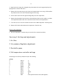
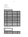
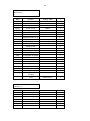
1
LABPLANT SD-05
SPRAY DRYER
SERVICE MANUAL
1.1
Servicing.
1.2
Faultfinding.
1.3
Fitting instructions.
1.4
Settings and adjustments.
Appendix.1. Parts lists.
Appendix.2. Wiring diagrams.
2
1.1 Service.
This procedure can be used as either a pre delivery inspection or as a guide to follow
when performing a planned maintenance service.
1.
With all the glassware in position connect the unit to a suitable mains supply, check
that the “mains on” light operates.
2. Switch the unit on at the “mains on” switch, allow time for the electronics to warm
up (15 minutes).
3. Check that both the “inlet” and “exhaust” temperatures are approximately the same.
(The temperature displayed should be the ambient temperature within the area in
which the spray dryer is sited.)
4. Switch on the peristaltic pump using the green touch contact, select the “pump flow”
reading using the multi-indicator switch. The pump flow is indicated, on a scale of 10
to 50, on the display adjacent to the multi-indicator switch.
A, Rotate the “pump speed” knob until the display reads 0, the
Pump should stop.
B. Check that the speed of the pump changes as the pump speed knob is rotated.
5. Turn off the pump.
6. Switch on the blower using the green touch contact, select the “air flow” reading
using the multi-indicator switch. The air speed is indicated, on a scale of 10 to 50, on
the display adjacent to the multi-indicator switch.
Use the green “up” button to increase the air flow to its maximum. NB. Maximum
flow has been reached when the display ceases to increase. If the machine is cold
the meter reading will stop at approximately 46.
7. With the airflow set to maximum switch on the heater, using the green touch
contact. Set the inlet temperature to 1000C, on the CAL temperature controller.
Check that, when the set temperature has been reached it remains stable.
8. Turn off the both the blower and the heater. Red touch switches.
9. Switch the multi-indicator switch to “compressor air flow”. The air pressure, in bars,
will be indicated, on the display adjacent to the multi-indicator switch.
10. Switch on the compressor using the appropriate green touch switch
11. Using the “compressor air pressure control” set the air pressure to maximum.
12. Using the de-blocker control check that the frequency of the de-blocking device can
be adjusted.
13. Check all the glassware for damage and clean the machine as necessary.
3
Servicing 2. Fault Finding.
When turned on at the mains the “Mains on” light does not illuminate.
Check the fuse in the main’s plug.
Check the line fuse F1 situated next to the main’s inlet.
Check the mains on indicator L1.
The inlet and exhaust temperatures are not the similar.
Are either approximately the same as the ambient temperature.
Disconnect the sensor, which is giving the incorrect reading,
Connect a new sensor and check that the displays are now similar.
If the temperatures are the same, fit the new sensor following the guidelines in the
next section.
The peristaltic pump does not work correctly.
Check the pumps power supply.
Check the pump drive motor.
The air blower does not start.
Check the power to the blower motor.
If power present, change the motor. If power is not present check the wiring to
the motor starting at the blower on switch.
The air blower makes an excessive noise when running or its speed varies.
Either the fan or the motor bearing is dry or damaged. Replace the fan-motor
assembly.
The air heater does not work when turned on in conjunction with the blower.
Check the power to the heater. If power present, change the heater, refer to
section 3.4. If power is not present check the wiring to the heater.
The heater cuts out before the set temperature has been reached.
Check the over temperature thermostat,
The needle on the de-blocking device does not move when switched on.
Check the air supply to the deblocker.
Strip down and clean the de-blocking device.
The compressor does not run when turned on.
Check the power to the compressor.
If power present change the compressor, refer to section 3.5. If power is not
present check the wiring to the compressor
The air pressure supplied by the compressor is insufficient.
Check the operation of the butterfly valve.
The compressor makes an excessive noise when running
Replace compressor.
4
Servicing 3. Fitting instructions.
1. Inlet temperature sensor
Removal of existing temperature sensor.
1.
Disconnected the power from the unit and isolate fully before commencing any work
described below.
2. Remove all the glassware from the unit.
3. Open both doors using the triangular key. Disconnect the earth tags and pull up the
spring bolts to remove the doors.
4. Remove the 8 screws securing the electrical compartment cover using a 2.5mm Allen
key. Remove the cover after disconnecting the earth tag.
5. Carefully remove the insulation from around the bend at the top of the heater
column, so that the input temperature probe and the over temperature sensor are
exposed.
6. Separate the thermocouple temperature probe wire from the over temperature
probe capillary tube.
7. Inside the electrical compartment disconnect the thermocouple wires from the CAL
temperature controller, contacts 1 & 2.
8. Pull the cable out through the grommet in the back of the electrical compartment.
9. Slacken the grub screw holding the sensor in position, and remove the sensor from its
housing. If the grub screw has been over-tightened it may be necessary to destroy the
sensor in order to remove it.
Fitting a new sensor.
1.
Thread the thermocouple cable through the grommet on the case and connect the
cable to the CAL controller.
2. Carefully fit the thermocouple into position in the inlet manifold.
3. Tighten the grub screw so that it just nips the thermocouple case, taking care not to
crush the stainless tube. The thermocouple should protrude into the air-stream by
approximately 15 to 20 mm.
4. Secure the thermocouple cable to the capillary tube and replace the insulation
around the inlet manifold.
5. Replace the electrical compartment cover and the doors, ensuring that all the earth
tags have been reconnected.
5
2. Exhaust temperature sensor.
Removal of the existing sensor.
1.
Disconnected the power from the unit and isolate fully before commencing any of
the work, as described below.
2. Remove all the glassware from the unit
3. Open both doors using the triangular key. Disconnect the earth tags and pull up the
spring bolts to remove the doors.
4. Using an 2.5mm Allen key, remove the 8 screws securing the electrical compartment
cover
5. On the outside of the machine remove the covers on the sliding glass support head.
Inside this head the thermocouple and the outlet pressure detector can be seen.
6. Loosen the grub screw holding the thermocouple, and carefully withdraw it through
the bottom of the bracket.
7. Thread the thermocouple back into the case and through the grommet in the control
box.
8. Unclip the thermocouple leads from the cable tie securing them to the motherboard.
9. Unplug the 2 way connector from the motherboard.
Refitting the probe.
1.
Connect the 2 way plug to the motherboard, fasten the thermocouple leads to the
pillar using a cable tie.
2. Thread the thermocouple through the grommet on the case where the other
thermocouple wire passes through.
3. Pass the thermocouple through the case and carefully fit the thermocouple tip into
its hole on the bracket.
4. Tighten the grub screw so it just nips the thermocouple case, taken care not to
crush the stainless tube. The thermocouple should protrude into the exhaust tube
the same distance as the outlet pressure pipe, (approx 15 to 20 mm).
5. Replace the electrical compartment cover and the doors, ensuring that all the earth
tags have been reconnected.
6
3. Air Blower.
Removal of the existing air blower.
1.
Disconnect the power from the unit and isolate fully before commencing any of
the work as described below.
2. Remove all the glassware from the unit.
3. Open both doors using the triangular key. Disconnect the earth tags and pull up
the spring bolts to remove the doors.
4. Remove the 8 screws securing the electrical compartment using a 2.5mm allen
key. Remove the cover after disconnecting the earth tag.
5. Remove the plug SK8 from the electrical motherboard and cut the cable tie to
allow the blower power lead to be removed from the electrical compartment.
6. Remove the power lead from the butterfly valve motor, 2 x push on tags.
7. Disconnect the heater from the flow control valve body by slackening the 3
accessible grub screws on the control valve flange.
8. Undo the 4 motor retaining nuts and remove the blower assembly.
9. With the fan assembly removed from the unit remove the flow control valve
from the blower flange, noting the orientation of the valve motor to the fan
housing.
10. Remove the two feet, complete with studs, from the air blower motor, noting
the position of the feet in respect to the blower assembly.
Fitting a replacement air blower and motor.
1. Check that the alignment of the new unit’s blower flange is correct.
2. Remove the foot, plate from the motor, and replace with the feet removed from the
old unit. Note. In order for the air blower and motor assembly to be correctly aligned
with the heater the feet should be fastened on the motor so that the centre of the
first stud is 65mm from the fan casing.
3. Fasten the flow control valve to the air blower flange, making sure that the valve
motor is in its correct position.
4. Fit the assembly back into the unit making sure that the flow control valve mates
correctly with the heater.
5. Replace the electrical compartment cover and the doors, ensuring that all the earth
tags have been reconnected.
7
4. Air heater.
Removal of the existing air heater.
1.
Disconnected the power from the unit and isolate fully before commencing any work
described below.
2. Remove all the glassware from the unit.
3. Open both doors using the triangular key. Disconnect the earth tags and pull up the
spring bolts to remove the doors.
4. Remove the 8 screws securing the electrical compartment cover using a 2.5mm Allen
key. Remove the cover after disconnecting the earth tag.
5. Disconnect the heater wiring from inside the electrical compartment.
6. Carefully remove the insulation from around the heater and disconnect the heater
from the flow control valve body by slackening the 3 accessible grub screws on the
control valve flange.
7. Remove the air blower assembly, as section 3,
8. Withdraw the heater from the inlet manifold.
Fitting a replacement heater.
1.
Slide the replacement heater into the inlet manifold, and refit the blower motor
assembly.
2. Reconnect the heater to the flow control valve.
3. Fit the heater wires back into the electrical compartment.
4. Replace the insulation around the heater
5. Rewire the heater before replacing the electrical compartment cover and doors,
ensuring that all the earth tags have been reconnected.
5. Compressor
Removal of existing compressor.
1. Disconnected the power from the unit and isolate fully before commencing any work
described below.
2. Remove all the glassware from the unit.
8
3. Open both doors using the triangular key. Disconnect the earth tags and pull up the
spring bolts to remove the doors.
4. Remove the 8 screws securing the electrical compartment cover using a 2.5mm Allen
key. Remove the cover after disconnecting the earth tag.
5. Pull out and remove the two pipes leading away from the compressor.
6. Remove the plug SK9 from the electrical motherboard and cut the cable tie to allow
the compressor power lead to be removed from the electrical compartment.
7. Turn the unit on to its side to allow access to the 4x M4 compressor retaining bolts.
8. Remove all 4 bolts and withdraw the compressor from the unit.
Fittina a new compressor
1. The new compressor is fitted using a reversal of the removal procedure.
Servicing 4, Settings and adjustments.
1. Air flow.
2. Air pressure, Regulator adjustment.
3. Peristaltic pump.
4. Cal temperature controller settings
All setting are as factory default except the following:
LEVEL
2
2
2
3
1
1
1
1
2
1
3
INPUT
UNIT
HI.SC
SP1.D
BAND
INT.T
DER.T
CYC.T
SP2.A
SET.2
UER
K
°C
270
SSD
47
0.8
4
1.0
DUHI
10
Hold up/down button until LOCK appears.
9
Press down button until NO.AL appears.
Change to ON.
.
5. Low mains voltage supply
The SD-05 can be run, successfully an 210 to 250 Volts A.C. Outside these limits the
unit will malfunction. If however the supply tends to be less than 220 Volts an
alteration to the wiring of an internal transformer will improve the performance of the
equipment.
To rewire the transformer.
6. 1. Disconnected the power from the unit and isolate fully before commencing any
work described below.
7. Open the units side door using the triangular key.
8. Remove the 8 screws securing the electrical compartment cover using a 2.5mm Allen
key. Remove the cover after disconnecting the earth tag.
9. Remove and move aside the three PCBs, mounted on the motherboard without
disconnecting the pipes.
10. The transformer, to be modified, is the smaller of the two mounted to the left of
the three PCBs. Slide the plastic terminal cover over the wires to gain access to the
connections.
11. Unsolder the two wires on the top tag , marked xxx ,and re-solder them to the next
solder tag. See the diagram below.
12. Replace the plastic terminal cover and the PCBs, reseal the electrical compartment
and replace the door.
10
Appendix 1
Parts lists.
Power supply P.C.B
Part No
Description
Code No
Qty.
R101-103
Resistor
SFR 25 2K7
3
R104-105
Resistor
SFR25 470R
2
R106-107
Resistor
SFR25 1K
2
C101-103
Capacitor
2200uF63V Elect
3
C104-105
Capacitor
4700uF 16V Elect
2
C106-110
Capacitor
220nF 100V Poly
5
C110-115
Capacitor
100nF 63V Poly
5
BR101-102
Bridge Rectifer
2KBB40
2
IC101-102
Voltage regulator
L78S24CV
2
IC103
Voltage regulator
L7924CV
1
IC104
Voltage Reference
LM369DRC
1
IC105
Voltage regulator
LM340T5
1
IC106
Voltage regulator
LM7905CT
1
IC107
Isolated supply
NME0505D
1
D101-103
Diode
1N4002
3
PL12
Connector 32 way
F104-104
P.C. Fuse
1
2amp
Transistor mounting
kit
Heatsink
See Drg L0440
P.C.B.
13593 issue 1
4
5
1
Signal conditioner P.C.B
SD-05
Signal
conditioner
P.C.B.
RV201-202
Trimmer
43P 100K
2
C201-204
Capacitor
1uF 35V tantalum
4
C205-208
Capacitor
100nF 63V tantalum
4
11
C209
Capacitor
100uF 10V tantalum
1
IC201-202
Amplifier
INA102KP
2
IC203-204
OP-Amp
LM741CN-8
2
S201
Gauge transducer
1
S202
1
PL13
Differential
transducer
Connector 32 way
TP20-29
10 way test socket
1
1
Bracket
See drg. L0540
1
IC socket
8 way t.p. d.i.l socket
2
IC socket
16 way t.p, d.i.l socket
2
P.C>B.
17593 issue 1
1
R301-302
Resistor
SFR25 470R
2
R303-306
Resistor
SFR25 100K
4
SD-05
Pump motor
P.C.B.
R307
Resistor
SFR25 10M
1
R308-313
Resistor
SFR25 10K
6
R314-315
Resistor
SFR25 2K2
2
R316
Resistor
KN350 R033
1
RV301-302
Trimmer
43P 10K
2
RV303
Trimmer
43P 1K
1
C301
Capicitor
100nF 63V poly
1
C302
Capicitor
2.2uF 50V elect
1
C303-304
Capicitor
10nF 63V poly
2
D301-302
Diode
1N4148
2
D303
Diode
1N4005
1
D304
Diode
BZX85C5V1
1
TR301
Transistor
BC212L
1
TR302
Transistor
TIP141
1
IC301
IC
LM324N
1
F301
P.C. Fuse
2amp
1
Link
Zero ohm link
1
PL15
32 way reversed
europlug
P.C.B
1
Heatsink for TR302
15953 issue1
1
1
14 way t.p d.i.l socket
1
Transistor mounting
kit
1
12
SD-04
Motherboar
d
R401
Resistor
SFR25 100R
1
C401
Capicitor
2200uF 50V elect
1
D401-407
Diode
1N4002
7
BR401
Bridge rectifer
2KBB40
1
FL401
Filter choke
RN112
1
F401
Fuse
3.15amp a/s 20mm
1
F402
Fuse
1amp a/s 20mm
1
PCB Fuseholder
2
PCB Fuseholder cover
2
O/L 401
Thermal trip
1amp
1
O/L402
Thermal trip
2amp
1
RL401-403
3PCO 10A Relay
3
Relay socket
3
Socket clip
3
RL404-405
SPCO 16A Relay
1
SK3
16 way IDC plug
1
SK4
16 way IDC dil header
1
SK5-6
5 Way header
2
SK7
4Way header
1
SK8-10
6 Way header
2
SK11
2 Way header
1
TP401-410
10 Way test socket
1
SK12
32 Way power socket
1
SK13
32 Way europlug
1
SK15
32 Way reversed
europlug
P.C.B
1
SD-05
Fascia p.c.b
R501-504
26593 issue 1
1
13
Thank you for reading this data sheet.
For pricing or for further information, please contact us at our UK Office, using the details
below.
UK Office
Keison Products,
P.O. Box 2124, Chelmsford, Essex, CM1 3UP, England.
Tel: +44 (0)1245 600560
Fax: +44 (0)1245 808399
Email: [email protected]
Please note - Product designs and specifications are subject to change without notice. The user is responsible for determining the
suitability of this product.