1
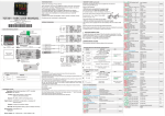
3 WIRING
DIAGRAM ATR111
PIXSYS
ATR111- B
PIXSYS
ATR111- AD
2 wire
I
2 wir e
4 /20 m A
+V D C PT C/N TC
6
7
8
9
10
11
1
12
1
M emo ry
2
3
M em ory
AND KEYS
Display normally shows
process value (ex. measured temperature),
but can also visualize setpoints or value of
entering data
ATR111
Visualize set, increase set
or scroll parameters
(whith fast advancement)
Visualize set, decrease set,
scroll parameters.
(whith fast advancement)
OUT 1
L1
FNC
SET
PIXSYS
Visualize setpoint (ex. programmed temperature):
press once for SET1 (Led Out1 flashes),
In configuration mode press with arrow
keys to modify value of visualized parameter.
OUT 2
4
5
6
7
8
9
10
11
Tc
+
5
S SR
Tc
+
4
+V D C PT C/N TC
230 V~
+
3
+
4 DISPLAYS
+
1
S SR
2
PT /NI 10 0 /1 K
Q1
Q1
-
V/ I
-
8A 230V
Resis ti ve
1/2H P
+
-
PT /NI 10 0 /1 K
12. ..3 5V. ..
1
4 /20 mA
+
V/ I
10A 230V
Resis ti ve
3/4H P
12/ 24V ~
I
Po we r
Po we r
12