1
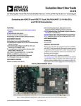
Evaluation Board User Guide
UG-182
One Technology Way • P.O. Box 9106 • Norwood, MA 02062-9106, U.S.A. • Tel: 781.329.4700 • Fax: 781.461.3113 • www.analog.com
Evaluating the AD9523-1 Clock Generator
FEATURES
GENERAL DESCRIPTION
Simple power connection using USB connection and
on-board LDO voltage regulators
LDOs are easily bypassed for power measurements
AC-coupled differential SMA connectors
SMA connectors for
2 reference inputs
2 PLL status outputs
1 reference test input
2 VCXO interface inputs/outputs
Microsoft Windows®–based evaluation software
with simple graphical user interface
On-board PLL loop filter
Easy access to digital I/O and diagnostic signals
via I/O header
Status LEDs for diagnostic signals
USB computer interface
Software calculator provides flexibility, allowing programming
of almost any rational input/output frequency ratio
This user guide describes the hardware and software of the
AD9523-1 evaluation boards. The evaluation board schematic
and PCB layout artwork can be found at www.analog.com.
The AD9523-1 is designed to support the clock requirements
for long-term evolution (LTE) and multicarrier GSM base station
designs. It relies on an external VCXO to provide the reference
jitter cleanup to achieve the restrictive low phase noise requirements necessary for acceptable data converter SNR performance.
The AD9523-1 evaluation board is a compact, easy-to-use platform for evaluating all features of the AD9523-1. A 122.88 MHz
VCXO is mounted on the evaluation board to provide a complete
solution.
The input receivers are configured as differential but the evaluation board has baluns to provide a single-ended input for easy
evaluation using common laboratory single-ended signal sources.
Output 8 is connected to an ADCLK905 clock buffer to provide
a way to evaluate an Analog Devices, Inc., buffer. Although the
ADCLK905 is a 1-to-1 buffer, the performance is similar to the
larger fanout buffer, for example, the 1-to-2 buffer, ADCLK925.
Output 1 and Output 9 are configured with baluns to provide a
single-ended output to drive most test equipment. Output 0 is
configured for differential zero delay operation.
09280-001
DIGITAL PICTURE OF EVALUATION BOARD
Figure 1. AD9523-1 Evaluation Board
PLEASE SEE THE LAST PAGE FOR AN IMPORTANT
WARNING AND LEGAL TERMS AND CONDITIONS.
Rev. 0 | Page 1 of 16
UG-182
Evaluation Board User Guide
TABLE OF CONTENTS
Features .............................................................................................. 1 Evaluation Board Software Operation............................................6 General Description ......................................................................... 1 Menu Bar of Main Window .........................................................7 Digital Picture of Evaluation Board ............................................... 1 Revision History ............................................................................... 2 Using the Software to Control the Functional Blocks of
AD9523-1 .......................................................................................8 Evaluation Board Hardware ............................................................ 3 PLL 1 Controls...............................................................................8 Setting Up Jumper Connections................................................. 3 PLL 2 Controls...............................................................................9 Setting Up the Power and PC Connections .............................. 3 Channel Divider Window ......................................................... 10 Setting Up the Signal Connections ............................................ 3 Output Driver Window ............................................................. 11 Setting Up the PLL2 Loop Filter Capacitor .............................. 3 EEPROM Control ...................................................................... 11 Bypassing the 6 V Wall Socket Power Supply........................... 3 Using the Evaluation Board to Program an AD9523-1 on a
Customer Board.............................................................................. 12 Using I2C Serial Port Mode ......................................................... 4 Evaluation Board Software Setup ................................................... 5 Quick Start Guide to the AD9523-1 ............................................ 13 Installing the Software ................................................................. 5 Using the Software........................................................................ 5 REVISION HISTORY
10/10—Revision 0: Initial Version
Rev. 0 | Page 2 of 16
Evaluation Board User Guide
UG-182
EVALUATION BOARD HARDWARE
The following instructions are for setting up the physical
connections to the AD9523-1 evaluation board.
SETTING UP THE SIGNAL CONNECTIONS
After setting up the power and PC connections, use the
following procedure to set up the signal connections:
SETTING UP JUMPER CONNECTIONS
The evaluation board is configured for proper PC control and
operation. If the jumpers are inadvertently moved, use Figure 2
and Figure 3 to reconfigure the board.
1.
2.
Connect a signal generator to REF A SMA Connector J9.
By default, the reference inputs on this evaluation board
are ac-coupled and terminated with 50 Ω to ground. An
amplitude setting of 6 dBm is sufficient.
Connect an oscilloscope, spectrum analyzer, or other lab
equipment to any of the OUTx SMA connectors on the
right side of the board. The output connectors are singleended outputs of a differential pair. A 50 Ω termination
should be placed on all unused differential output pairs.
SETTING UP THE PLL2 LOOP FILTER CAPACITOR
09280-002
PLL2 requires an external loop filter capacitor. To achieve the
best jitter performance, reference Capacitor C6 to LDO_VCO,
Pin 12. This can done by installing R6 and removing R4. These
connections should have been performed at the factory.
Figure 2. USB and SPI Jumper Connections
SETTING UP THE POWER AND PC CONNECTIONS
Set up the power and PC connections as follows:
1.
2.
3.
4.
Install the AD9523-1 evaluation software before connecting the evaluation board to the PC for the first time (see
the Installing the Software section). Administrative
privileges are required for installation.
Connect the 6 V wall adapter to Connector P7 of the evaluation board.
Connect the USB cables to the evaluation board and the
computer.
Found New Hardware Wizard automatically appears
when the evaluation board is connected. Select Install the
software automatically and then click Next.
The Found New Hardware Wizard may appear twice, and
a system restart may be required.
Refer to the Evaluation Board Software Setup section for details
on running the AD9523-1 evaluation board software.
BYPASSING THE 6 V WALL SOCKET POWER
SUPPLY
The evaluation board contains a dc-to-dc converter to step down
the 6 V to 2.2 V and 4 V. Linear regulators are then used to
further regulate the 2.2 V to 1.8 V supply domain and the 4 V to
the 3.3 V supply domain. The evaluation board can be configured
to bypass the dc-to-dc converter and linear regulators or the dcto-dc converter only. This is useful for measuring AD9523-1
power consumption. Refer to the evaluation board schematics
provided on the CD in the evaluation board kit (also available at
www.analog.com) for further details.
Bypass the 6 V power supply (dc-to-dc converter and linear
regulators) as follows:
1.
2.
Note that it is very important to not have the 6 V supply
connected to the evaluation board while using external
supplies. To be safe, remove the inductors from each linear
regulator output (L4 to L15).
Connect a bench power supply to each of the supply pins
on Header TP3 through Header TP15. If the inductors
were not removed in Step 1, then some of the supply pins
are connected together on the evaluation board and
damage to the external supply and/or evaluation board
may occur.
Bypass the 6 V power supply (dc-to-dc converter only) as
follows:
1.
2.
3.
Rev. 0 | Page 3 of 16
Remove L1, L2, L3, R39, R41, R40, and R42.
Connect a 2.2 V bench supply to Connector P19.
Connect a 4 V bench supply to the L1 pad.
UG-182
Evaluation Board User Guide
USING I2C SERIAL PORT MODE
To use the I2C serial Port mode, follow these steps:
1.
2.
3.
4.
5.
6.
09280-004
7.
Figure 3. I2C Address Jumper Setting
Rev. 0 | Page 4 of 16
Power down the board and shut down the software.
Set Jumpers P11 and P13 to the I2C position (see Figure 2).
Select the desired I2C address using Jumpers P5 and P6
(see Figure 3). Note that setting P5 and P6 low is reserved
for SPI mode.
Power up the board and connect the USB cable to the board.
Start the evaluation board software.
On the evaluation software, select Configure Serial Port
from the I/O menu (see the I/O Menu section).
Click the Reset Serial Port button, and then click Detect
Current Configuration (see Figure 8). A dialog box
should appear to acknowledge the I2C mode and address.
Evaluation Board User Guide
UG-182
EVALUATION BOARD SOFTWARE SETUP
The main window of the evaluation board software appears.
Proceed to the Evaluation Board Software Operation
section for more details about using the software.
The instructions included in this section are for setting up the
AD9523-1 evaluation board software.
INSTALLING THE SOFTWARE
1.
2.
3.
4.
Insert the AD9523-1 evaluation software CD-ROM
into a PC CD disc drive.
Click My Computer, and then double-click the
AD9523-1EV CD icon.
A window opens showing the contents of the CD divided
into four sections: data sheet, layout, schematic, and software.
The readme.txt file contains a description of the CD-ROM
contents, as well as any last minute instructions or
information.
Double-click the Software folder, and then double-click
AD9523-1Eval_Setup1.1.0.exe. Follow the installation
instructions.
The default location for the evaluation software is
C:\Program Files\Analog Devices\AD9523-1
Eval Software\.
If there are any updates to the evaluation software on a
supplemental CD or in the \Software\Updates folder, be
sure to copy the new .exe file, as well as any setup files, to
the default location.
If the evaluation board was not found, a dialog box appears
that allows you to select an evaluation board to use while
the software runs in standalone mode. Standalone mode is
useful for viewing and generating register setup files.
a. If the evaluation board was not automatically detected
when it was connected, choose Select Evaluation
Board from the I/O menu, and then select Ezssp-0,
Ezssp-1, or Ezssp-2 (see Figure 4).
09280-006
4.
Do not connect the evaluation board until the software
installation is complete. To install the software,
Figure 4. Select USB Device Window
5.
USING THE SOFTWARE
If you connect the evaluation board while the evaluation
board software is running, the window shown in Figure 5
usually appears to prompt you to load the evaluation board
with the evaluation board software settings or to read the
current evaluation board settings into the software.
After the evaluation software has been installed, you can run
the software as follows:
3.
Power up and connect the evaluation board to the PC.
Double-click AD9523-1 Eval Software to run the
AD9523-1 evaluation software.
A hardware installation window appears. Depending on
whether the evaluation board was found by the software, the
text in this window is either light blue, indicating that the
evaluation board was found, or red, indicating that the
evaluation board was not found.
If the evaluation board was found, click in the window
when the Evaluation Software Ready message appears.
09280-005
1.
2.
Figure 5. SYNC Evaluation Software Window
Rev. 0 | Page 5 of 16
UG-182
Evaluation Board User Guide
EVALUATION BOARD SOFTWARE OPERATION
When a subsection window closes after clicking OK, the
WRITE button under REGISTER W/R on the main window
may start blinking. This indicates that there are settings that
have not been loaded to the AD9523-1 evaluation board. Click
WRITE to load these settings to the evaluation board.
09280-106
The main window of the AD9523-1 evaluation board software
comprises subsections that correspond to the major functional
blocks of the AD9523-1 (see Figure 6). These subsections, most
of which have their own window, are outlined in this section.
From the main window, the window for each functional block
can be accessed by clicking the appropriate box.
Figure 6. AD9523-1 Evaluation Software Main Window
Rev. 0 | Page 6 of 16
Evaluation Board User Guide
UG-182
MENU BAR OF MAIN WINDOW
File Menu
The File menu allows you to load a previously saved AD9523-1
setup file or to save a new AD9523-1 setup file. A setup file
(.stp) is a text file that contains the AD9523-1 register setup file,
plus any evaluation board settings.
To load a previously saved setup file, select Load Setup from
the File menu. Note that you must still perform a VCO
calibration. Alternatively, to save a new setup file, select Save
Setup from the File menu.
09280-009
To exit the evaluation software, select Exit from the File menu.
However, note that you must save your setup before exiting; no
checking is performed to ensure that the existing setup is saved.
I/O Menu
Figure 8. Serial Port Configuration Window
View Menu
The Debug window, accessed by selecting Debug Window from
the View menu, allows you to write and read registers directly and
to force the various configuration pins high or low (see Figure 9).
09280-008
The AD9523-1 evaluation system allows one PC to control
multiple evaluation boards. The Select USB Device window,
accessed by choosing Select Evaluation Board from the I/O
menu, allows you to select which evaluation board the software
controls (see Figure 7). Click Refresh List to detect a recently
connected evaluation board.
Figure 7. Select USB Device Window
The serial port configuration window allows you to control how
the USB controller interacts with the AD9523-1 serial port. If
you are using I2C mode, this window allows you to select which
address to use. Note that it needs to correspond to the settings
of Jumpers P5 and P6 on the evaluation board. You can also
click the Detect Current Configuration button to have the
evaluation software discover which I2C address is active.
Rev. 0 | Page 7 of 16
09280-010
Selecting Configure Serial Port from the I/O menu allows you
to control how the USB controller interacts with the AD9523-1
serial port (see Figure 8) by configuring Register 0x0000 (shown
as 0000h in Figure 10).
Figure 9. Debug Window
UG-182
Evaluation Board User Guide
SYNC, PD (Power Down), and RESET
The Register Map Values window, accessed by selecting
Register Map Window from the View menu, allows you to read
registers (see Figure 10).
The SYNC, PD, and RESET buttons allow you to control the
SYNC, PD, and RESET pins on the AD9523-1.
Each button has three options: Strobe, Latch, and Release.
Strobe activates the pin and then releases it. Latch holds the pin
active until the Release command is issued.
PLL 1 CONTROLS
09280-011
The PLL 1 box in the main window (see Figure 6) allows you to
configure the PLL1 parameters. Clicking the PLL 1 box in the
main window, shown in Figure 11, opens a window to allow
configuration of PLL1 (see Figure 12 ).
09280-012
Figure 10. Register Map Window
Help Menu
Selecting Help from the Help menu opens the About AD9523-1
window, which contains information such as revision number,
region information, and contact information.
USING THE SOFTWARE TO CONTROL THE
FUNCTIONAL BLOCKS OF AD9523-1
Figure 11. PLL1 Box (in Main Window)
Clicking each individual box in the PLL 1 Controls window
opens a new window to allow configuration of that block (see
Figure 13 for an example for the REF A Divider window).
REGISTER W/R
The REGISTER W/R (write/read) section in Figure 6 has three
buttons and three check boxes.
The WRITE button transfers the values stored in the evaluation
software to the evaluation board. It blinks red when register
values have changed.
The READ button transfers the values stored in the evaluation
board to the evaluation software.
Selecting the All check box transfers all of the registers when
the WRITE button is clicked. When this box is not selected,
only the registers whose value has changed are written.
09280-112
The UPDATE button issues an I/O update command by writing
to the I/O update register.
Figure 12. PLL1 Controls Window
Selecting the Auto check box adjacent to the WRITE button
forces the evaluation software to write the register changes to
the evaluation board automatically when they occur.
Selecting the Auto check box adjacent to the UPDATE box
forces the evaluation software to issue an I/O update command
whenever registers are written to the AD9523-1.
Rev. 0 | Page 8 of 16
Evaluation Board User Guide
UG-182
Reference (REF) Divider Window
The Charge Pump Setup window shown in Figure 15 is
accessed by clicking the CHARGE PUMP box in Figure 12.
This window is most often used to vary the charge pump
current.
PLL 2 CONTROLS
09280-013
Clicking the PLL 2 box from the main window (see Figure 16)
opens a window to allow configuration of PLL 2 (see Figure 17).
Figure 13. Reference A or Reference B Divider Window
The reference divider window shown in Figure 13 is accessed by
clicking the REF A Divider box in Figure 12. It allows you to
set the reference divider. There is a corresponding window for
both REF A and REF B dividers.
09280-116
Feedback (N) Divider Window
Figure 16. PLL 2 Box (in Main Window)
09280-014
Clicking each individual box in the PLL 2 Controls window
opens a new window to allow configuration of that block.
Figure 14. N Divider Window
The feedback divider window shown in Figure 14 is accessed by
clicking the N DIVIDER box in Figure 12. It allows you to set
the feedback divider.
09280-017
Charge Pump Window
09280-016
Figure 17. PLL 2 Controls Window
Figure 15. Charge Pump Window
Rev. 0 | Page 9 of 16
UG-182
Evaluation Board User Guide
Feedback (N) Divider Window
09280-018
09280-021
CHANNEL DIVIDER WINDOW
Figure 20. Channel Divider Window
The N Divider window shown in Figure 18 is accessed by
clicking the N DIVIDER box in Figure 17. It allows you to set
the feedback divider.
VCO Divider 1 and Divider 2
The VCO dividers controls are located in the PLL 2 Controls
window shown in Figure 17. They allow you to set the frequency
feeding the channels. Channel OUT4 through Channel OUT9
can be configured for either Divider 1 or Divider 2. If Divider 2
is not required, it is recommended that it be turned off for best
spurious performance.
Figure 21. Channel Divider
You can also vary the phase offset by changing the phase offset
bits setting under the Divider Phase box in Figure 20. However,
for the new phase to take effect, the SYNC signal must be
toggled, by clicking the SYNC button shown in Figure 22 and
selecting Strobe SyncB.
09280-025
Charge Pump Window
The channel divider window shown in Figure 20 is accessed by
clicking the appropriate channel divider (see Figure 21) in the
main window shown in Figure 6. It is usually sufficient to
change only the divide ratio, because the evaluation software and
the AD9523-1 duty cycle correction feature ensure that the
output duty cycle remains very close to 50%.
09280-027
Figure 18. N Divider Window
09280-020
Figure 22. Toggling SYNC Signal
Figure 19. Charge Pump Window
The Charge Pump Setup window shown in Figure 19 is
accessed by clicking the CHARGE PUMP box in Figure 17.
This window is most often used to vary the charge pump
current.
Rev. 0 | Page 10 of 16
Evaluation Board User Guide
UG-182
EEPROM CONTROL
09280-023
OUTPUT DRIVER WINDOW
Figure 25. EEPROM Control Window
The EEPROM Control window shown in Figure 25 is accessed
by clicking the EEPROM button near the lower left quadrant of
the main window.
To store the current register settings of the AD9523-1 to the
EEPROM, click the Program EEPROM button. Visually
confirm the EEPROM Status Registers section on the right
side of the window to verify that the operation is successful.
To load the values stored in the EEPROM,
09280-022
1.
2.
The output driver window shown in Figure 23 is accessed by
clicking any of the triangular output driver symbols on the right
side of the main window (see Figure 24).
3.
09280-026
Figure 23. Output Driver Window
Disconnect the 6 V power connector to power down the
AD9523-1.
Ensure that the EEPROM pin is pulled high by placing the
P4 EEPROM_SEL jumper of the evaluation board across
the center and left (high) pin (see Figure 3).
Reconnect the 6 V power supply. This automatically loads
the EEPROM settings into the AD9523-1. The programmed
settings can be observed at the outputs. In addition, a
window opens (see Figure 26). Click the second option to
read from the AD9523-1. This loads the control software
with the current register settings that were programmed by
the EEPROM.
Figure 24. Output Drivers
It is important to power down unused outputs on the evaluation
board because they can be a major source of unwanted spurs.
09280-024
The outputs are ac-coupled with 100 Ω differential resistors on
each output. This termination scheme is ideal for LVPECL
drivers. However, this scheme degrades the CMOS driver
performance. Improved CMOS driver performance is achieved
by removing the 100 Ω resistors.
Figure 26. SYNC Evaluation Software Window
Rev. 0 | Page 11 of 16
UG-182
Evaluation Board User Guide
USING THE EVALUATION BOARD TO PROGRAM AN AD9523-1 ON A CUSTOMER BOARD
This guide explains how to use an AD9523-1 evaluation board
to program an AD9523-1 on a customer board via the I2C interface. It assumes that the user has access to the I2C pins via a
header on the target board, and knows the assigned address of
the target I2C device.
3.
4.
5.
Move Jumpers P13 and P11 to the I2C position.
Select the desired I2C address for the AD9523-1 evaluation
board using Jumper P5 and Jumper P6. Note that the P5 =
P6 = low setting is reserved for SPI mode. Also, this I2C
address should not conflict with the I2C address of the
target AD9523-1.
Attach a jumper cable from the SDIO_SDA pin of
Header P2 of the evaluation board to the SDA pin on the
target board.
Repeat Step 3 for both the SCLK_SCL pin and the GND
pin of the AD9523-1 evaluation board, attaching jumper
cables to the SCL pin and ground pin of the target board,
respectively.
On the evaluation software, select Configure Serial Port
from the I/O menu. This window is shown in Figure 27.
7.
Click Reset Serial Port and then click Detect Current
Configuration. A dialog box appears and acknowledges
the I2C mode and address. The evaluation software starts at
I2C Address 0x060 and stops at the first valid I2C address
that it finds. If the target I2C address is different from the
one automatically selected, select the I2C address of the
target AD9523-1 from the list, and click OK.
From the View menu on the menu bar, select Debug
Window. From the Debug window (see Figure 9), click the
I2C Debug button under the I/O Port Status section. The
window shown in Figure 28 appears.
08746-023
1.
2.
6.
Figure 28. Evaluation Software I2C Debug Window
8.
Figure 27. Evaluation Software Serial Port Configuration
9.
Rev. 0 | Page 12 of 16
Enter the I2C address set by Jumper P5 and Jumper P6 on
the AD9523-1 evaluation board, and click Ping. The user
should see a green ACK message as shown in Figure 28.
Repeat this step for the I2C address of the target AD9523-1.
If ACK is returned for both addresses, the remote AD9523-1
is ready to be programmed.
If the ping test fails, double-check the cabling between the
boards, as well as the I2C address of the target AD9523-1.
Ensure that the I2C address of the AD9523-1 on the evaluation board is different from the target AD9523-1. Also,
disconnect the jumper cable, and make sure that I2C mode
is working properly on the AD9523-1 evaluation board.
Proceed to program the target AD9523-1 with the desired
settings.
a. When finished, click the EEPROM button on the
main window to access the EEPROM window.
b. Click Program EEPROM to write the settings to the
EEPROM.
Evaluation Board User Guide
UG-182
QUICK START GUIDE TO THE AD9523-1
The AD9523-1 can be initialized at startup from either the
EEPROM or from SPI settings. The AD9523-1 evaluation board
ships with initial settings programmed in the EEPROM. It is
advised that the user first use the preprogrammed EEPROM
settings before proceeding onto software control.
To load the provided setup file:
1.
2.
To load the values stored in the EEPROM:
1.
2.
3.
4.
Ensure that the EEPROM pin is pulled high by placing the
P4 EEPROM_SEL jumper of the evaluation board across
the center and left (high) pin (see Figure 3).
Connect a signal generator to REF A SMA Connector J9.
By default, the reference inputs on this evaluation board
are ac-coupled and terminated with 50 Ω to ground. An
amplitude setting of 6 dBm is sufficient and the frequency
should be 30.72 MHz.
Connect an oscilloscope, spectrum analyzer, or other lab
equipment to the OUT1 SMA connector on the right side
of the board. This output connector is a single-ended
output of a differential pair.
Connect the 6 V power supply. This automatically loads
the EEPROM settings into the AD9523-1 (the EEPROM
configurations are similar as shown in Figure 6).
3.
4.
5.
6.
7.
Rev. 0 | Page 13 of 16
Follow the instructions provided in the Evaluation Board
Software Setup section.
Ensure that the EEPROM pin is pulled low by placing the
P4 EEPROM_SEL jumper of the evaluation board across
the center and right (low) pin (see Figure 3).
Connect a signal generator to REF A SMA Connector J9.
By default, the reference inputs on this evaluation board
are ac-coupled and terminated with 50 Ω to ground. An
amplitude setting of 6 dBm is sufficient and the frequency
should be 30.72 MHz.
Connect the 6 V power supply.
Provided on the CD is a setup file named
AD9523-1_983plan_122p88MHz_VCXO_DoublerON.stp
located in the Setup Files directory. Load this setup file
using the File menu from the main software window.
The main window should appear as shown in Figure 6.
Click the CAL VCO button located in the PLL 2 box of
Figure 6.
Connect an oscilloscope, spectrum analyzer, or other lab
equipment to the OUT1 SMA connector on the right
side of the board. This output connector is a single-ended
output of a differential pair. A picture of phase noise profile
is located in the same directory as the setup file with the
same file name (with the .png extension).
UG-182
Evaluation Board User Guide
NOTES
Rev. 0 | Page 14 of 16
Evaluation Board User Guide
UG-182
NOTES
Rev. 0 | Page 15 of 16
UG-182
Evaluation Board User Guide
NOTES
ESD Caution
ESD (electrostatic discharge) sensitive device. Charged devices and circuit boards can discharge without detection. Although this product features patented or proprietary protection
circuitry, damage may occur on devices subjected to high energy ESD. Therefore, proper ESD precautions should be taken to avoid performance degradation or loss of functionality.
Legal Terms and Conditions
By using the evaluation board discussed herein (together with any tools, components documentation or support materials, the “Evaluation Board”), you are agreeing to be bound by the terms and conditions
set forth below (“Agreement”) unless you have purchased the Evaluation Board, in which case the Analog Devices Standard Terms and Conditions of Sale shall govern. Do not use the Evaluation Board until you
have read and agreed to the Agreement. Your use of the Evaluation Board shall signify your acceptance of the Agreement. This Agreement is made by and between you (“Customer”) and Analog Devices, Inc.
(“ADI”), with its principal place of business at One Technology Way, Norwood, MA 02062, USA. Subject to the terms and conditions of the Agreement, ADI hereby grants to Customer a free, limited, personal,
temporary, non-exclusive, non-sublicensable, non-transferable license to use the Evaluation Board FOR EVALUATION PURPOSES ONLY. Customer understands and agrees that the Evaluation Board is provided
for the sole and exclusive purpose referenced above, and agrees not to use the Evaluation Board for any other purpose. Furthermore, the license granted is expressly made subject to the following additional
limitations: Customer shall not (i) rent, lease, display, sell, transfer, assign, sublicense, or distribute the Evaluation Board; and (ii) permit any Third Party to access the Evaluation Board. As used herein, the term
“Third Party” includes any entity other than ADI, Customer, their employees, affiliates and in-house consultants. The Evaluation Board is NOT sold to Customer; all rights not expressly granted herein, including
ownership of the Evaluation Board, are reserved by ADI. CONFIDENTIALITY. This Agreement and the Evaluation Board shall all be considered the confidential and proprietary information of ADI. Customer may
not disclose or transfer any portion of the Evaluation Board to any other party for any reason. Upon discontinuation of use of the Evaluation Board or termination of this Agreement, Customer agrees to
promptly return the Evaluation Board to ADI. ADDITIONAL RESTRICTIONS. Customer may not disassemble, decompile or reverse engineer chips on the Evaluation Board. Customer shall inform ADI of any
occurred damages or any modifications or alterations it makes to the Evaluation Board, including but not limited to soldering or any other activity that affects the material content of the Evaluation Board.
Modifications to the Evaluation Board must comply with applicable law, including but not limited to the RoHS Directive. TERMINATION. ADI may terminate this Agreement at any time upon giving written notice
to Customer. Customer agrees to return to ADI the Evaluation Board at that time. LIMITATION OF LIABILITY. THE EVALUATION BOARD PROVIDED HEREUNDER IS PROVIDED “AS IS” AND ADI MAKES NO
WARRANTIES OR REPRESENTATIONS OF ANY KIND WITH RESPECT TO IT. ADI SPECIFICALLY DISCLAIMS ANY REPRESENTATIONS, ENDORSEMENTS, GUARANTEES, OR WARRANTIES, EXPRESS OR IMPLIED, RELATED
TO THE EVALUATION BOARD INCLUDING, BUT NOT LIMITED TO, THE IMPLIED WARRANTY OF MERCHANTABILITY, TITLE, FITNESS FOR A PARTICULAR PURPOSE OR NONINFRINGEMENT OF INTELLECTUAL
PROPERTY RIGHTS. IN NO EVENT WILL ADI AND ITS LICENSORS BE LIABLE FOR ANY INCIDENTAL, SPECIAL, INDIRECT, OR CONSEQUENTIAL DAMAGES RESULTING FROM CUSTOMER’S POSSESSION OR USE OF
THE EVALUATION BOARD, INCLUDING BUT NOT LIMITED TO LOST PROFITS, DELAY COSTS, LABOR COSTS OR LOSS OF GOODWILL. ADI’S TOTAL LIABILITY FROM ANY AND ALL CAUSES SHALL BE LIMITED TO THE
AMOUNT OF ONE HUNDRED US DOLLARS ($100.00). EXPORT. Customer agrees that it will not directly or indirectly export the Evaluation Board to another country, and that it will comply with all applicable
United States federal laws and regulations relating to exports. GOVERNING LAW. This Agreement shall be governed by and construed in accordance with the substantive laws of the Commonwealth of
Massachusetts (excluding conflict of law rules). Any legal action regarding this Agreement will be heard in the state or federal courts having jurisdiction in Suffolk County, Massachusetts, and Customer hereby
submits to the personal jurisdiction and venue of such courts. The United Nations Convention on Contracts for the International Sale of Goods shall not apply to this Agreement and is expressly disclaimed.
©2010 Analog Devices, Inc. All rights reserved. Trademarks and
registered trademarks are the property of their respective owners.
UG09280-0-10/10(0)
Rev. 0 | Page 16 of 16