1
Remote Control Reference Design
4.3
USB Receive Dongle
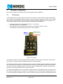
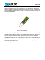
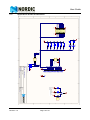
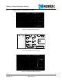
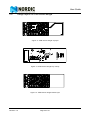
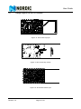
The USB dongle contains all the components that are necessary for a finished product.
The matching network for the nRF24L01 has the same layout as in the reference design from the
datasheet with only some small component changes to compensate for the smaller PCB. The 50 ohm reference point will be between C5 and L4, where L4 is used to match the antenna to this 50 ohm impedance.
The following design alterations are likely to the USB receive dongle:
•
•
Tools from Silicon Laboratories are required to reprogram the USB receive dongle with your software. The top side of the USB receive dongle has a 4-pin programming interface for Silicon Laboratories ISP tools. The 4-pin connector will likely be omitted from the BOM of a production model.
The LED and button are placed on the the USB receive dongle. If your application does not need
these functions, it is easy to disregard the components without having to alter the PCB layout.
Note: If you need the button and/or LED and find it inconvenient that they are on the bottom side,
the simplest modification is to turn the USB connector upside down.
•
•
It is possible to reduce the size of the USB receive dongle by using a chip antenna or another
antenna configuration, choosing a more compact USB connector or, altering the layout. If you
choose to do so, the antenna matching network must be redesigned.
The antenna is matched for best reception when the dongle is placed in a USB slot of a computer,
and without a plastic housing. Adding housing can affect the antenna resulting in the antenna
matching needing changed.
Revision 1.0
Page 13 of 21