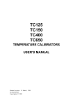
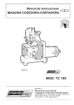
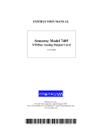
1
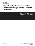
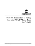
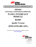
TC650 Fan Control Demo Board User’s Guide 2002 Microchip Technology Inc. DS51304A Note the following details of the code protection feature on Microchip devices: • Microchip products meet the specification contained in their particular Microchip Data Sheet. • Microchip believes that its family of products is one of the most secure families of its kind on the market today, when used in the intended manner and under normal conditions. • There are dishonest and possibly illegal methods used to breach the code protection feature. All of these methods, to our knowledge, require using the Microchip products in a manner outside the operating specifications contained in Microchip's Data Sheets. Most likely, the person doing so is engaged in theft of intellectual property. • Microchip is willing to work with the customer who is concerned about the integrity of their code. • Neither Microchip nor any other semiconductor manufacturer can guarantee the security of their code. Code protection does not mean that we are guaranteeing the product as “unbreakable.” Code protection is constantly evolving. We at Microchip are committed to continuously improving the code protection features of our products. Information contained in this publication regarding device applications and the like is intended through suggestion only and may be superseded by updates. It is your responsibility to ensure that your application meets with your specifications. No representation or warranty is given and no liability is assumed by Microchip Technology Incorporated with respect to the accuracy or use of such information, or infringement of patents or other intellectual property rights arising from such use or otherwise. Use of Microchip’s products as critical components in life support systems is not authorized except with express written approval by Microchip. No licenses are conveyed, implicitly or otherwise, under any intellectual property rights. Trademarks The Microchip name and logo, the Microchip logo, KEELOQ, MPLAB, PIC, PICmicro, PICSTART and PRO MATE are registered trademarks of Microchip Technology Incorporated in the U.S.A. and other countries. FilterLab, microID, MXDEV, MXLAB, PICMASTER, SEEVAL and The Embedded Control Solutions Company are registered trademarks of Microchip Technology Incorporated in the U.S.A. dsPIC, dsPICDEM.net, ECONOMONITOR, FanSense, FlexROM, fuzzyLAB, In-Circuit Serial Programming, ICSP, ICEPIC, microPort, Migratable Memory, MPASM, MPLIB, MPLINK, MPSIM, PICC, PICDEM, PICDEM.net, rfPIC, Select Mode and Total Endurance are trademarks of Microchip Technology Incorporated in the U.S.A. and other countries. Serialized Quick Turn Programming (SQTP) is a service mark of Microchip Technology Incorporated in the U.S.A. All other trademarks mentioned herein are property of their respective companies. © 2002, Microchip Technology Incorporated, Printed in the U.S.A., All Rights Reserved. Printed on recycled paper. Microchip received QS-9000 quality system certification for its worldwide headquarters, design and wafer fabrication facilities in Chandler and Tempe, Arizona in July 1999 and Mountain View, California in March 2002. The Company’s quality system processes and procedures are QS-9000 compliant for its PICmicro® 8-bit MCUs, KEELOQ® code hopping devices, Serial EEPROMs, microperipherals, non-volatile memory and analog products. In addition, Microchip’s quality system for the design and manufacture of development systems is ISO 9001 certified. DS51304A - page ii 2002 Microchip Technology Inc. TC650 Fan Control Demo Board User’s Guide Table of Contents Chapter 1. General Information 1.1 Introduction ..................................................................................... 1 1.2 The TC650 Fan Control Demo Board ............................................. 2 1.3 Reference Documents .................................................................... 3 Chapter 2. Getting Started 2.1 TC650 Demo Board Functional Description ................................... 5 2.2 Typical Module Configurations ....................................................... 6 Appendix A. Board Layout A.1 Introduction ..................................................................................... 9 A.2 Board Schematic and Layout .......................................................... 9 A.3 Demo Board Components ............................................................ 10 Worldwide Sales and Service ............................................................................. 12 2002 Microchip Technology Inc. DS51304A-page iii TC650 Fan Control Demo Board User’s Guide NOTES: DS51304A-page iv 2002 Microchip Technology Inc. TC650 Fan Control Demo Board User’s Guide Chapter 1. General Information 1.1 INTRODUCTION Thank you for purchasing the TC650 Fan Control Demo Board from Microchip Technology Inc. The TC650 Fan Control Demo Board is an evaluation tool that allows the user to quickly prototype fan control circuits based on Microchip’s TC650 or TC651 pulse width modulation (PWM) Fan Control ICs. A logic level MOSFET drive device allows the fan control demo board to be used with virtually any brushless DC fan. A red LED status indicator gives a visual indication of an over temperature alert (temperature is 10ºC higher (typically) than the high temperature limit). The TC650 Demo Board has the following features: 1. Complete implementation of TC650 or TC651 fan control circuitry on a 1.0" x 1.0" board. 2. Temperature proportional fan speed control. 3. Over temperature alert. 4. Installs directly into user's end equipment. 5. Speeds up prototyping, system development and system thermal characterization. 2002 Microchip Technology Inc. DS51304A-page 1 TC650 Fan Control Demo Board User’s Guide 1.2 THE TC650 FAN CONTROL DEMO BOARD The TC650 Fan Control Demo Board (Figure 1-1) measures only 1.0 inch x 1.0 inch, allowing direct installation to the user’s end equipment for system evaluation. An external 2.8V to 5.5V power supply is required for the operation of the TC650. The TC650 Demo Board is equipped with the following components: 1. 2. 3. 4. 5. 1 µF, 1206 Chip Capacitor. 1 kΩ, 1206 Chip Resistor. 4.5 mA Miniature Red LED. Logic Level MOSFET (Si2302). TC650AEVUA Fan Control IC. If any component is damaged or missing, please contact your nearest Microchip sales office, listed on the back of this publication. FIGURE 1-1 DS51304A-page 2 The TC650/TC651 Fan Control Demo Board 2002 Microchip Technology Inc. General Information 1.3 REFERENCE DOCUMENTS Other Reference Documents may be obtained by contacting your nearest Microchip sales office (listed on the back of this document) or by visiting the Microchip website (www.microchip.com). • Technical Library CD-ROM, (DS00161) or the individual data sheet: - TC650/TC651 Data Sheet, (DS21450) • Analog & Interface Families Data Book 2002, (DS00207) • 2002 Technical Documentation Analog & Interface Product Families CD-ROM, (DS51205) • Suppressing Acoustic Noise in Pulse Width Modulation (PWM) Fan Speed Control Systems Application Note, (AN771) • Speed Error in Pulse Width Modulation (PWM) Fan Control Systems Application Note, (AN772) • TC65X Fan Speed Controller Family Sell Sheet, (DS21625) • TC650DEMO and TC652DEMO Fan Controller Demo Boards for the TC650/1/2/3 Sell Sheet, (DS51254) 2002 Microchip Technology Inc. DS51304A-page 3 TC650 Fan Control Demo Board User’s Guide NOTES: DS51304A-page 4 2002 Microchip Technology Inc. TC650 Fan Control Demo Board User’s Guide Chapter 2. Getting Started This chapter describes the TC650 Demo Board’s configuration, how it functions, and lists typical fan demo board operating configurations for fan applications. The board is equipped with a TC650AEVUA device, which features a minimum temperature limit (TL) of 25°C (40% duty cycle) and a maximum temperature limit (TH) of 45°C (100% duty cycle). 2.1 TC650 DEMO BOARD FUNCTIONAL DESCRIPTION 2.1.1. PWM Output The pulse width modulation (PWM) pin is designed to drive a low cost transistor or MOSFET as the low side power switching element in the system. A 2N2222 type small signal (BJT) can be used for fans up to 300 mA. For larger current fans (up to 1 amp), a logic-level N-channel MOSFET must be used. Since the system relies on pulse width modulation, rather than linear power control, the dissipation in the power switch is kept to a minimum. Generally, very small devices, such as the TO-92 or SOT, will suffice. Test Point TP1 can be connected to an oscilloscope for observing PWM output characteristics. 2.1.2. SHDN The fan can be unconditionally shut down by pulling the SHDN pin low. This function can be implemented by removing jumper JP1, then grounding pin 3. For details, see Figure A-2 in the Appendix A section. 2.1.3. Over Temperature Alert The TC650/TC651 devices include an on-chip over temperature alarm signal (TOVER) that goes low when the temperature of the chip exceeds TH by 10ºC (typical). When the junction temperature rises to approximately 55°C ( = TH +10°C = 45°C + 10°C), the TOVER signal is asserted and the red LED light turns on. 2002 Microchip Technology Inc. DS51304A-page 5 TC650 Fan Control Demo Board User’s Guide 2.2 TYPICAL MODULE CONFIGURATIONS The TC650/TC651 integrated temperature sensors and brushless DC fan speed controllers are designed to drive an external transistor or MOSFET for modulating power to the fan. The PWM pin has a minimum source current of 5 mA and a minimum sink current of 1 mA. Bipolar transistors or MOSFETs may be used as the power switching element. Table 2-1 lists the suggested output drive device vs. fan motor current. Additionally, see Figure 2-1 for output drive configuration options. TABLE 2-1: SUGGESTED OUTPUT DRIVE DEVICE VS. FAN MOTOR CURRENT Full Speed Fan Motor Current Logic MOSFET (Q1- Standard) Bipolar Transistor (Optional) 100 mA — X 200 mA X X 300 mA X X 400 mA X — 500 mA X — 600 mA X — 700 mA X — 800 mA X — 900 mA X — 1A X — VDD VDD Fan Fan RBASE VOUT FIGURE 2-1: DS51304A-page 6 Q1 VOUT Q1 GND GND a) Single Bipolar Transistor b) N-Channel MOSFET Output Driver Configuration Options 2002 Microchip Technology Inc. Getting Started 2.2.1 Using Logic Level MOSFETs The TC650 Demo Board is equipped with a logic level MOSFET (Si2302). Using a MOSFET results in low system voltage losses and reduced output loading on the TC650/651. The low RDSON of this MOSFET (0.085Ω) enables it to be used in high current fan applications (>200 mA). Table 2-2 lists examples of MOSFETs that can be utilized for Q1. TABLE 2-2: MOSFETs FOR Q1 Device VDS (V) VGS(TH) (V) ID (A) RDS(ON) (Ω) Si2302 20 1.5 2.8 0.085 Si4410 30 3.0 8 0.02 MGSF1N02E 20 1.5 0.75 0.10 2.2.2 Using Bipolar Driver Transistors Fans with operating currents of 50 mA to 300 mA can be driven using a single bipolar transistor. The transistor must have sufficient gain (hFE) in order to reach saturation when the base is driven with 5 mA of current (minimum output current spec of TC650/651) and the collector is conducting full fan current. A 2N2222A is a good choice. A base current limiting resistor is required with bipolar transistors. The correct value for this resistor can be determined as follows: EQUATION: RBASE = VOH – VBE(SAT) IR(BASE) Table 2-3 lists suggested Bipolar transistors for Q1. TABLE 2-3: BIPOLAR TRANSISTORS FOR Q1 (VDD = 5.0V, IBASE = 5 mA) VCE(SAT) (mV) hFE VBR(CEO) (V) IC (mA) RBASE (Ω) MPS2222 100 30 30 150 800 MPS2222A 100 30 40 150 800 2N4400 150 20 40 100 820 2N4401 150 20 40 100 820 MPS6601 180 50 25 250 780 MPS6602 180 50 40 250 780 Device Note: 2002 Microchip Technology Inc. The values that are listed in the table represent typical values for TA = 25°C. DS51304A-page 7 TC650 Fan Control Demo Board User’s Guide 2.2.3 System Connection for +5V Operation Figure 2-2 shows typical wiring connections to the Fan Control Demo Board. The fan operating voltage is +12V while the Fan Control Board operates from a supply voltage of +5V. TC650DEMO +5V VDD GND TC650 GND +12V Fan Connector GNDFAN VFAN Power Supply Fan FIGURE 2-2: Note: DS51304A-page 8 Typical Wiring Connections to Fan Module for 12V Fan and 5V Demo Board Supply The grounds for the 12V fan supply and the 5V VDD supply should be tied together at the power supply. 2002 Microchip Technology Inc. TC650 Fan Control Demo Board User’s Guide Appendix A. Board Layout A.1 INTRODUCTION This appendix contains general information concerning the schematics, layout and components for the TC650 Demo Board. A.2 BOARD SCHEMATIC AND LAYOUT Figure A-1 depicts the layout for the top and bottom layers of the TC650 Demo Board. Figure A-2 shows a functional block diagram for the TC650 Demo Board. +5V +VFAN FAN TP1 R1 Q1 JP1 C1 U1 TC650/TC651 (Top Layer) FIGURE A-1: + D1 TC650/TC651 (Bottom Layer) TC650/TC651 Demo Board, Top and Bottom Layers 2002 Microchip Technology Inc. DS51304A-page 9 TC650 Fan Control Demo Board User’s Guide VDD + VFAN C1 1 µF Test Point (TP1) 1 TC650/TC651 VDD 8 Q1 Si2302 PWM U1 R1 1k 7 2 Shutdown Input GND NC D1 TOVER 3 SHDN TOVER LED (Red) 6 JP1 4 FIGURE A-2: A.3 GND NC 5 TC650 Demo Board Functional Block Diagram DEMO BOARD COMPONENTS Table A-1 lists the various components and associated values that comprise the TC650 Demo Board. TABLE A-1: FAN CONTROL DEMO BOARD COMPONENTS AND VALUES Component Typical Value Comments C1 1 µF, 1206 chip capacitor Power supply filter. D1 4.5 mA miniature red LED LED lights when TOVER output is LOW (active). Q1 Logic Level MOSFET Transistor output option. A logic level MOSFET (Si2302) is used on the TC650 to accommodate various types of fans. The output drive device can also be an NPN transistor, depending on cost constraints and fan current. R1 1 kΩ, 1206 chip resistor D1 current limiting resistor. U1 TC650AEVUA; low temperature limit: TL 25°C, high temperature limit: TH 45°C TC650 or TC651 fan control ICs. DS51304A-page 10 2002 Microchip Technology Inc. Board Layout NOTES: 2002 Microchip Technology Inc. DS51304A-page 11 WORLDWIDE SALES AND SERVICE AMERICAS ASIA/PACIFIC Corporate Office Australia 2355 West Chandler Blvd. Chandler, AZ 85224-6199 Tel: 480-792-7200 Fax: 480-792-7277 Technical Support: 480-792-7627 Web Address: http://www.microchip.com Microchip Technology Australia Pty Ltd Suite 22, 41 Rawson Street Epping 2121, NSW Australia Tel: 61-2-9868-6733 Fax: 61-2-9868-6755 Rocky Mountain China - Beijing 2355 West Chandler Blvd. Chandler, AZ 85224-6199 Tel: 480-792-7966 Fax: 480-792-4338 Atlanta 3780 Mansell Road, Suite 130 Alpharetta, GA 30022 Tel: 770-640-0034 Fax: 770-640-0307 Boston 2 Lan Drive, Suite 120 Westford, MA 01886 Tel: 978-692-3848 Fax: 978-692-3821 Chicago 333 Pierce Road, Suite 180 Itasca, IL 60143 Tel: 630-285-0071 Fax: 630-285-0075 Dallas 4570 Westgrove Drive, Suite 160 Addison, TX 75001 Tel: 972-818-7423 Fax: 972-818-2924 Detroit Tri-Atria Office Building 32255 Northwestern Highway, Suite 190 Farmington Hills, MI 48334 Tel: 248-538-2250 Fax: 248-538-2260 Kokomo 2767 S. Albright Road Kokomo, Indiana 46902 Tel: 765-864-8360 Fax: 765-864-8387 Los Angeles 18201 Von Karman, Suite 1090 Irvine, CA 92612 Tel: 949-263-1888 Fax: 949-263-1338 San Jose Microchip Technology Inc. 2107 North First Street, Suite 590 San Jose, CA 95131 Tel: 408-436-7950 Fax: 408-436-7955 Toronto 6285 Northam Drive, Suite 108 Mississauga, Ontario L4V 1X5, Canada Tel: 905-673-0699 Fax: 905-673-6509 Microchip Technology Consulting (Shanghai) Co., Ltd., Beijing Liaison Office Unit 915 Bei Hai Wan Tai Bldg. No. 6 Chaoyangmen Beidajie Beijing, 100027, No. China Tel: 86-10-85282100 Fax: 86-10-85282104 China - Chengdu Microchip Technology Consulting (Shanghai) Co., Ltd., Chengdu Liaison Office Rm. 2401-2402, 24th Floor, Ming Xing Financial Tower No. 88 TIDU Street Chengdu 610016, China Tel: 86-28-86766200 Fax: 86-28-86766599 China - Fuzhou Microchip Technology Consulting (Shanghai) Co., Ltd., Fuzhou Liaison Office Unit 28F, World Trade Plaza No. 71 Wusi Road Fuzhou 350001, China Tel: 86-591-7503506 Fax: 86-591-7503521 China - Hong Kong SAR Microchip Technology Hongkong Ltd. Unit 901-6, Tower 2, Metroplaza 223 Hing Fong Road Kwai Fong, N.T., Hong Kong Tel: 852-2401-1200 Fax: 852-2401-3431 China - Shanghai Microchip Technology Consulting (Shanghai) Co., Ltd. Room 701, Bldg. B Far East International Plaza No. 317 Xian Xia Road Shanghai, 200051 Tel: 86-21-6275-5700 Fax: 86-21-6275-5060 China - Shenzhen Microchip Technology Consulting (Shanghai) Co., Ltd., Shenzhen Liaison Office Rm. 1812, 18/F, Building A, United Plaza No. 5022 Binhe Road, Futian District Shenzhen 518033, China Tel: 86-755-82901380 Fax: 86-755-82966626 China - Qingdao Rm. B503, Fullhope Plaza, No. 12 Hong Kong Central Rd. Qingdao 266071, China Tel: 86-532-5027355 Fax: 86-532-5027205 India Microchip Technology Inc. India Liaison Office Divyasree Chambers 1 Floor, Wing A (A3/A4) No. 11, O’Shaugnessey Road Bangalore, 560 025, India Tel: 91-80-2290061 Fax: 91-80-2290062 Japan Microchip Technology Japan K.K. Benex S-1 6F 3-18-20, Shinyokohama Kohoku-Ku, Yokohama-shi Kanagawa, 222-0033, Japan Tel: 81-45-471- 6166 Fax: 81-45-471-6122 Korea Microchip Technology Korea 168-1, Youngbo Bldg. 3 Floor Samsung-Dong, Kangnam-Ku Seoul, Korea 135-882 Tel: 82-2-554-7200 Fax: 82-2-558-5934 Singapore Microchip Technology Singapore Pte Ltd. 200 Middle Road #07-02 Prime Centre Singapore, 188980 Tel: 65-6334-8870 Fax: 65-6334-8850 Taiwan Microchip Technology (Barbados) Inc., Taiwan Branch 11F-3, No. 207 Tung Hua North Road Taipei, 105, Taiwan Tel: 886-2-2717-7175 Fax: 886-2-2545-0139 EUROPE Austria Microchip Technology Austria GmbH Durisolstrasse 2 A-4600 Wels Austria Tel: 43-7242-2244-399 Fax: 43-7242-2244-393 Denmark Microchip Technology Nordic ApS Regus Business Centre Lautrup hoj 1-3 Ballerup DK-2750 Denmark Tel: 45 4420 9895 Fax: 45 4420 9910 France Microchip Technology SARL Parc d’Activite du Moulin de Massy 43 Rue du Saule Trapu Batiment A - ler Etage 91300 Massy, France Tel: 33-1-69-53-63-20 Fax: 33-1-69-30-90-79 Germany Microchip Technology GmbH Steinheilstrasse 10 D-85737 Ismaning, Germany Tel: 49-89-627-144 0 Fax: 49-89-627-144-44 Italy Microchip Technology SRL Centro Direzionale Colleoni Palazzo Taurus 1 V. Le Colleoni 1 20041 Agrate Brianza Milan, Italy Tel: 39-039-65791-1 Fax: 39-039-6899883 United Kingdom Microchip Ltd. 505 Eskdale Road Winnersh Triangle Wokingham Berkshire, England RG41 5TU Tel: 44 118 921 5869 Fax: 44-118 921-5820 12/05/02 DS51304A-page 12 2002 Microchip Technology Inc.