1
UG-01080
2013.4.25
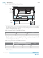
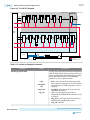
Two PHY IP Core Instances Each with Non-Bonded Channels
16-47
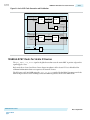
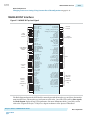
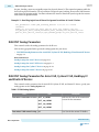
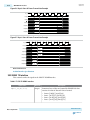
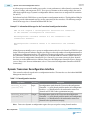
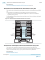
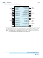
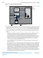
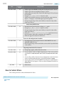
Note: Because all of the channels in a transceiver bank share a PLL, this original numbering allows the
Fitter to select the optimal CMU PLL from a placement perspective by considering all of the TX PLLs
in the bank.
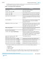
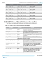
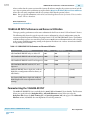
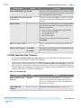
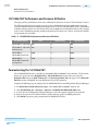
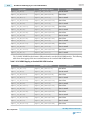
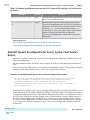
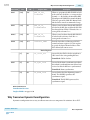
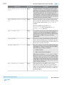
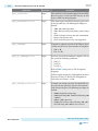
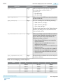
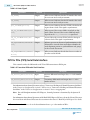
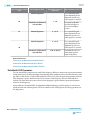
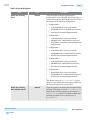
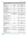
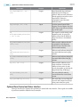
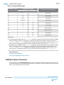
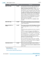
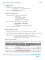
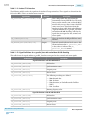
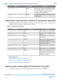
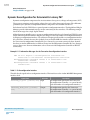
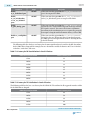
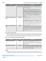
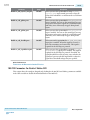
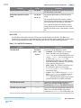
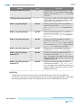
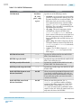
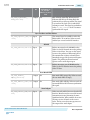
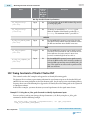
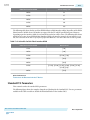
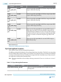
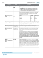
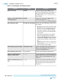
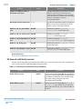
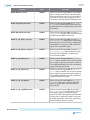
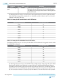
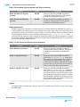
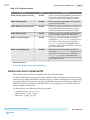
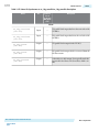
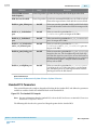
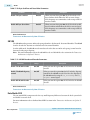
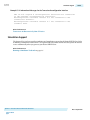
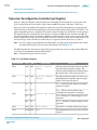
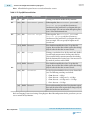
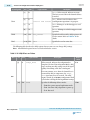
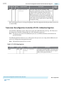
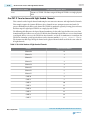
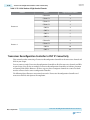
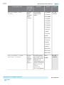
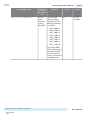
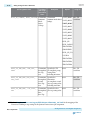
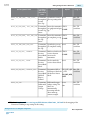
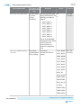
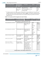
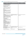
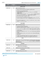
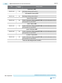
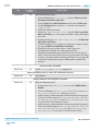
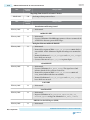
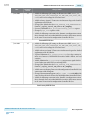
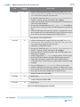
The following table shows the channel numbers for post-Fitter and hardware simulations. At this point, you
should have assigned channels to pins of the device.
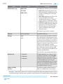
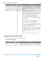
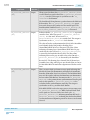
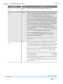
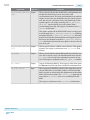
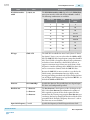
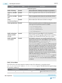
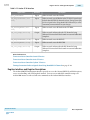
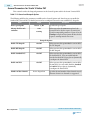
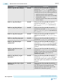
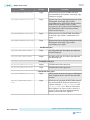
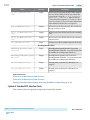
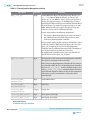
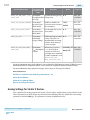
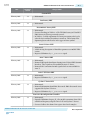
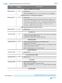
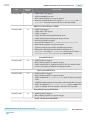
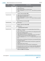
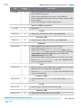
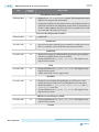
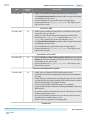
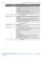
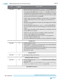
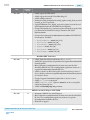
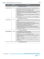
Table 16-31: Post-Fit Logical Channel Numbers for Eight Bonded Channels
Channel
Logical Channel Number
Channel 0
0
Channel 1
1
Channel 2
2
Channel 3
3
CMU (0-4)
8-12
Channel 4
4
Channel 5
5
CMU (5-7)
13-15
Channel 6
6
Channel 7
7
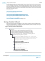
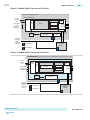
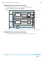
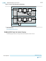
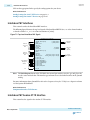
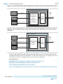
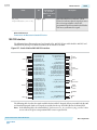
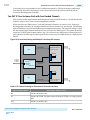
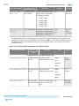
Two PHY IP Core Instances Each with Non-Bonded Channels
This section describes two instances with non-bonded channels.
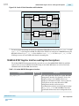
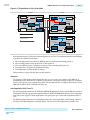
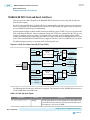
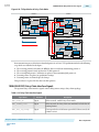
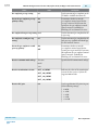
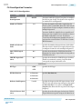
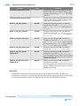
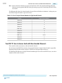
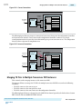
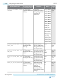
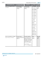
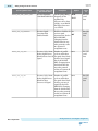
For each transceiver PHY IP core instance, the Quartus II software assigns the data channels sequentially
beginning at logical address 0 and assigns the TX PLLs the subsequent logical addresses.
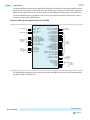
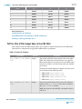
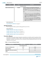
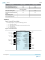
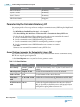
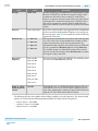
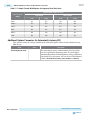
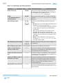
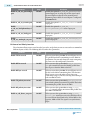
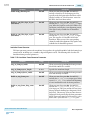
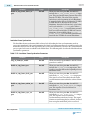
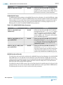
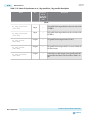
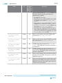
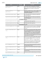
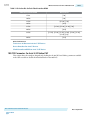
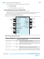
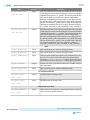
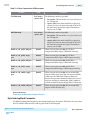
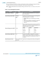
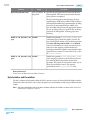
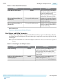
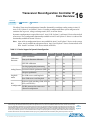
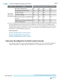
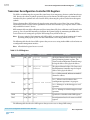
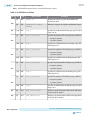
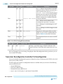
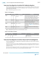
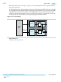
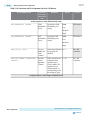
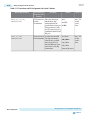
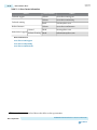
The following table illustrates the logical channel numbering for two transceiver PHY IP cores, one with 4
channels and one with 2 channels.
Transceiver Reconfiguration Controller IP Core Overview
Feedback
Altera Corporation