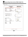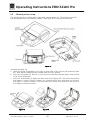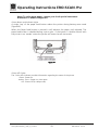
1
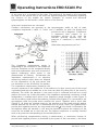
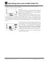
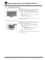
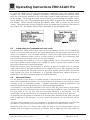
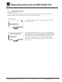
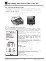
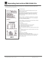
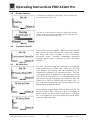
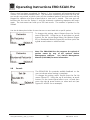
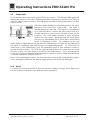
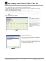
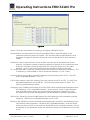
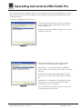
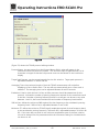
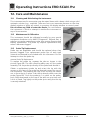
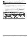
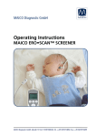
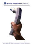
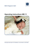
Operating Instructions EROCSCAN Pro
8.4
Connecting the cradle to the Printer
Use the included printer connection cable to connect the cradle to the printer. Connect
the appropriate end of the connection cable into the serial data port at the rear of the
printer. Connect the opposite end of the data cable into the printer connector on the
underside of the cradle (Figure 47).
Place the two-position button located on the upper right of the top side of the cradle in
the raised position for printer use (Figure 48)
Figure 47
Figure 48
8.5
Printing with the Thermal Paper Printer
Be sure the printer power is on and the button on the cradle is in the printer position.
Place the instrument gently in the cradle. A printer icon should appear on the display
and the test results should begin printing immediately.
DPOAE Printout:
Figure 49 shows a sample DPOAE printout from the
thermal paper printer.
The header shows the protocol name in the first line
followed by the date/time of the test, test number,
instrument serial number, probe serial number, and
firmware version.
Patient number is indicated or a blank line is provided to
write in the name. (See section 8.7 for information on
using numbered patients).
The ear (Right or Left) and the test result (Pass or Refer)
will be indicated on the printout.
Figure 49
Geba_EROSCANPro_E_REV_a_12a.docx
Data table:
F2 = the f2 frequency
P1 = the sound pressure level of f1
P2 = the sound pressure level of f2
DP = the level of the emission in dB SPL
NF = the noise floor in dB SPL
SNR = the signal-to-noise ratio (DP level minus the noise floor)
P = indicates that the pass criteria has been met for the
indicated frequency
Graph:
Vertical axis = SNR (dB)
Horizontal axis = f2 frequency tested (Hz)
30
850 041/2 01/12