1
E1/100BASE-FX Interface Converter User Manual
Storage temperature:
Humidity:
-20℃~80℃
5%~90% (no condensation)
4 Installation and Panel description
4.1 Unpacking (stand alone E1 to Optical Ethernet Interface Converter)
Check the accessories and spare parts when opens the package. In case of missing, immediately contact
our offices or agencies. Check for the following items:
■ One E1 to Optical Ethernet Interface Converter
■ An Operation manual
■ A supply cord
■ Two plugs for coaxial cable
In case of any damage in transportation, contact our offices or agencies.
4.2 Front and rear panel of the stand alone device
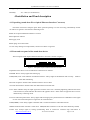
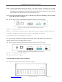
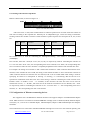
The front panel of the Optical Ethernet Interface Converter is shown in figure 3.
Figure 3
front panel of Optical Ethernet Interface Converter
Explanations for the two rows of indicators at the left are as follows:
POWER: Power. Always lights after starting up.
LINK(ETH): Link. Link indicator of Ethernet interface. Always lights if the Ethernet link correctly.
Flickers
when data transfering.
RX: Data reception. Flickers when the data interface receives data.
TX: Data transmission. Flickers when the data interface transmits data.
LOF: Alarm indicator lamp for input signal out-of-frame in E1 line. Constantly lightening indicates the alarm
with local device; flash indicates the alarm with opposite device. Alarm status of opposite device can be
detected only at framing mode.
LOS: E1 link interruption alarm. Always lights after starting up till synchronization is established. It also lights
in case of E1 link interruption or signal loss in communication.
LINK(FIBER): Link. Always lights if the fiber link is connected. Flickers when data transfer
SPEED: Indicator fiber interface’s work rate is 100M(The fiber interface’s work rate of this kind only 100M)
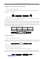
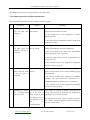
LOOP: Test. Always lights in testing (transmitting local or remote E1 interface loop instructions or
http://www.inmidas.com.cn
Tel:+86-010-51662447
Page 5 of 12