1
E1/100BASE-FX Interface Converter User Manual
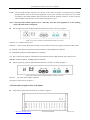
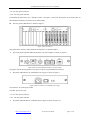
Figure 13 The figure two for the rack
E1 interface line will fetch out from BNC socket or RJ45 socket which are on the rear panel, Ethernet
interface line also from the RJ45 socket on the rear panel, fiber interface too.
5. Applications of FE1&10/100Base-T Bridge
5.1 Definition of balanced twisted-pair wire sequence for RJ45 interface
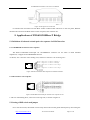
5.1.1 10/100BASE-T interface wire sequence
The RJ45 Unshielded twisted-pair for 10/100BASE-T interface can use DCE or DTE standard
stipulations, it support AUTO MDI/MDX function.
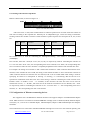
As shown, wire 1 and wire 2 are sending wire, and wire 3 and wire 6 are receiving wire.
1
2
3
4
5
6
7
8
TX+(Positive of data sending )
TX-(Negative of data sending)
RX+(Positive of data receiving)
Unused
Unused
RX-(Negative of data receiving)
Unused
Unused
Figure 13 RJ45 Twisted-Pair Wire Sequence for Ethernet Interface
1
2
3
4
5
6
7
8
5.1.2 E1 interface wire sequence
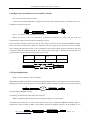
Figure 14 RJ45 balanced twisted-pair interface wire sequence for E1
1 and 2 are transmitting lines, 4 and 5 are receiving lines, as shown in figure 14.
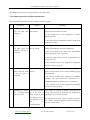
5.2 Setting of DIP switch and jumper
For a rack mount unit, the module can be easily drawn out from the guide channel just by unscrewing the
http://www.inmidas.com.cn
Tel:+86-010-51662447
Page 9 of 12