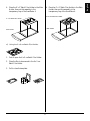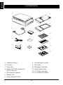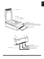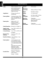
1
Microtek ScanMaker 4 User’s Manual English Copyright 1999 by Microtek International, Inc. All rights reserved. Trademarks Microtek, ScanMaker, and ScanWizard are trademarks of Microtek International, Inc. IBM PC is the trademark of International Business Machines Corporation. Windows and MS-DOS are trademarks of Microsoft Corporation. Other product or company names are trademarks or registered trademarks of their respective holders. Important Documents that you scan may be protected under copyright law. The unauthorized use of such documents could be a violation of the rights of the copyright holder. Microtek bears no responsibility for the unauthorized use of copyrighted materials. Doc. No. I49-002071, C May 1999 Microtek Lab, Inc. 3715 Doolittle Drive Redondo Beach, CA 90278-1226 Main: 310-297-5000 Sales: 800-654-4160 FAX: 310-297-5050 BBS: 310-297-5102 Technical Support: 310-297-5151 AutoTech fax back system: 310-297-5101 http://www.microtekusa.com Microtek International, Inc. 6, Industry East Road 3 Science Based Industrial Park Hsinchu, 30077, Taiwan, R.O.C. TEL: 886-3-5772155 FAX: 886-3-5772598 Microtek Europe B.V. Max Euwelaan 68 NL-3062 MA Rotterdam The Netherlands TEL: 31-10-2425688 FAX: 31-10-2425699 Federal Communications Commission (FCC) Statement This equipment (Trade name: ScanMaker 4, Model name: MRS-1200TP) has been tested and found to comply with the limits for a Class B digital device, pursuant to Part 15 of the FCC Rules. These limits are designed to provide reasonable protection against harmful interference in a residential installation. This equipment generates, uses and can radiate radio frequency energy and, if not installed and used in accordance with the instructions, may cause harmful interference to radio communications. However, there is no guarantee that interference will not occur in a particular installation. If this equipment does cause harmful interference to radio or television reception, which can be determined by turning the equipment off and on, the user is encouraged to try to correct the interference by one or more of the following measures: • • • • Reorient/relocate the receiving antenna. Increase the separation between the equipment and receiver. Connect the equipment into an outlet on a circuit different from that to which the receiver is connected. Consult the dealer or an experienced radio/TV technician for help. Note: A shielded interface cable with ferrite cord installed on scanner connector end must be used with this equipment. CAUTION Changes or modifications not expressly approved by the manufacturer responsible for compliance could void the user's authority to operate the equipment. ii Introduction ............................................................................................................ 1 Before You Begin .................................................................................................... 1 Installation under Windows 95/98 .......................................................................... 2 1. Installing the interface card ................................................................................................ 2 2. Checking interface card status ........................................................................................... 2 3. Installing software .............................................................................................................. 3 4. Resetting the scanner’s SCSI ID if necessary ........................................................................ 3 5. Connecting the scanner ..................................................................................................... 4 6. Checking scanner status .................................................................................................... 4 7. Testing your scanner .......................................................................................................... 5 Troubleshooting for Windows 95/98 ..................................................................................... 6 Installation under Windows NT 4.0 ......................................................................... 8 1. Resetting the scanner's SCSI ID if necessary ........................................................................ 8 2. Installing the interface card ................................................................................................ 8 3. Checking your Windows NT configuration ......................................................................... 8 4. Installing software .............................................................................................................. 9 5. Connecting the scanner ..................................................................................................... 9 6. Testing your scanner ........................................................................................................ 10 Troubleshooting for Windows NT 4.0 .................................................................................. 11 Installation under Macintosh ................................................................................ 12 1. Resetting the scanner’s SCSI ID if necessary ...................................................................... 12 2. Connecting the scanner ................................................................................................... 12 3. Installing software ............................................................................................................ 13 4. Scanning images .............................................................................................................. 13 Using the Manuals ............................................................................................................... 13 Operating the Scanner .......................................................................................... 14 Performing the power-on test .............................................................................................. 14 Positioning a document ....................................................................................................... 14 A: Placing reflective materials ........................................................................................ 14 B: Scanning thick documents ........................................................................................ 14 C: Placing transparent films ........................................................................................... 15 Using the universal glass film holder ....................................................................... 15 Using the main holder ............................................................................................ 16 a) Using the 35mm batch slide holder .................................................................. 16 b) Using the 35mm batch filmstrip holder ............................................................ 16 iii English Contents English c) Using the 4" x 5" batch film holder .................................................................. 16 d) Using the 6 x 9 cm batch film holder ............................................................... 17 Miscellaneous ....................................................................................................... 18 Returning your scanner for repairs ...................................................................................... 18 Locking the carriage ............................................................................................................ 18 Locking the ScanMaker 4 for shipping ................................................................................. 18 Lamp Replacement .............................................................................................................. 19 Components ......................................................................................................... 20 Specifications ........................................................................................................ 22 iv Before You Begin 1. Unpacking your scanner and checking components An image scanner is a device that captures and converts illustrations, graphics, photographs, or text into electronic files that can be edited or enhanced and then incorporated in printed documents or multimedia presentations. Open your scanner package and check the components as stated in your components list (see page 20). If any component is missing, call Microtek Sales. The single-pass, 36-bit, high-resolution ScanMaker 4 has been specifically designed and engineered for the discriminating scanner user, who demands rich, detailed images suitable for any preprocess or multimedia need. 2. Unlocking the scanner The ScanMaker 4 color flatbed scanner scans reflective originals, but also features internal media trays for scanning positive or negative film in a variety of industry-standard formats. Your scanner has a locking screw to protect the scanner carriage mechanism during shipping. Before you operate the scanner, you need to disengage the locking screw. The ScanMaker 4 includes 36-bit throughput capability for delivering images with more image data than 30- or 24-bit scanner are capable of capturing, superior optics and hardware components, as well as Microtek ScanWizard scanner controller software. Using a coin or a screwdriver, turn the locking screw counterclockwise to unlock it. When successfully unlocked, the screw will push out a little, nearly even with the bottom of the scanner. Basic Requirements For the PC: • Pentium, or compatibles • Microsoft Windows 95/98 or NT • CD-ROM drive (internal or external) • 16MB RAM • At least 100MB available hard disk space • Super VGA Color display with 256 colors or better For the Macintosh: • Apple Power Mac or compatibles • System 7.5 or higher Turn locking screw counterclockwise to unlock the scanner. • CD-ROM drive (internal or external) • 16MB RAM • At least 100MB available hard disk space • Super VGA Color display with 256 colors or better 1 English Introduction English Installation under Windows 95/98 2. Checking interface card status To install under Windows 95/98, take the steps below: 1. 2. 3. 4. 5. 6. 7. When you run Windows 95/98, the Adaptec AVA2902E SCSI adapter is detected and the driver is automatically installed. Make your Windows 95/98 CD-ROM ready for use. Some computers may prompt you to load Windows 95/98 software during your installing AVA-2902E driver. Follow steps below to check. Install the interface card in your computer Check the interface card status Install software Reset the scanner’s SCSI ID if necessary Connect the scanner and computer Check the scanner status Test your scanner 1. Turn on your computer, click Start, Settings, and select Control Panel. 1. Installing the interface card 2. Double-click on the System icon in Control Panel and select Device Manager from the top. Before installing the interface card supplied with your scanner, make sure you turn off your computer and peripherals. Then follow the steps below: 3. Double-click on “SCSI controllers” to display the screen below. 1. Shut down your computer and unplug the power cord. Next, remove the cover from your computer. 2. Look for an available PCI card slot (typically white or ivory) in your computer, remove the slot cover, and insert the Adaptec AVA-2902E into the slot. Push the card in to make sure it’s seated all the way in the slot. 290 2E The result of the check is displayed here. The message “Adaptec AIC-7850 PCI SCSI Controller” displays indicates that the driver is installed and the AVA-2902E interface card works properly. Ca rd PCI expansion slots (typically white or ivory) If a conflict exists, either of the following will occur: • a yellow exclamation mark appears next to the phrase: Adaptec AIC-7850 PCI SCSI Controller - or • nothing is listed under “SCSI Controllers”. In either case, refer to the Troubleshooting section. This is important, as an improper card connection will make you unable to use your scanner, and you will then have to remove the computer case and restart the card all over again. 3. Replace the cover of the computer, then plug the power cord back in. 2 Click Adobe Acrobat Reader, then follow screen instructions until installation is complete. Acrobat Reader is necessary for reading the manuals on your CD-ROM. Insert the Microtek CD-ROM into your CD-ROM drive. The Microtek Scanner Software installer should come up automatically, and list the software available for you. Click on each software program in the order they appear on your screen to install all of the components. 4. Resetting the scanner’s SCSI ID if necessary Note: If the Microtek Scanner Software is not automatically displayed on the screen, click Start, select Run and type d:\cdsetup (where d: is your CDROM drive). Step 1 Install documentation reader This procedure is provided as a reference. You may or may not need to change the SCSI ID on your scanner. Install Microtek ScanWizard ScanWizard is a Twain driver used for the scanner to work with various applications. ScanWizard cannot be used by itself and requires another program in order to work. A SCSI ID is a number assigned to each SCSI device in your daisy chain to differentiate the devices from one another. The SCSI ID for your Microtek scanner is factory-set to 6. 1. Click Microtek ScanWizard, then follow screen instructions to start installation. You won't need to change the SCSI ID on your scanner unless another SCSI device on your system (such as external hard drive, additional scanner, etc.) is using the same number. 2 During installation, choose “Adaptec SCSI Interface Card” option as your interface type. Locate the SCSI ID switch, use a small pin (or a small screwdriver) to press either of the small black openings located above or below the SCSI ID. Pressing the upper opening “-” decreases the SCSI ID number; pressing the lower opening “+” increases the number. 3. When installation is complete, the Microtek ScanWizard for Windows group appears as a folder in the Programs menu. Step 2 Install software application Install each software application by clicking on the individual program options. Step 3 _ 6 Install Microtek DCR + DCR is Microtek’s proprietary color calibration technology for use with Microtek color scanners. With DCR installed, your scanner is capable of capturing extremely accurate color images. Valid SCSI ID numbers are 0 to 6. Do not use SCSI ID #7, which is used to carry a self-test for the scanner and make the carriage move back and forth. SCSI ID #8 and #9 are also not used. 3 English Step 4 3. Installing software English 5. Connecting the scanner 6. Checking scanner status Before connecting the scanner to your computer, make sure the scanner driver (ScanWizard) is installed. Take the following steps to connect. When running Windows, ALWAYS turn on the scanner before the computer. If you don't, Windows will not be able to “see” your scanner. 1. Shut down your computer. 1. Click Start, Settings, and select Control Panel. 2. Connect the card and the scanner; using the SCSI cable that provided in the scanner package. Make sure your scanner and computer are turned off when you perform the connection. 2. Double-click on the System icon in Control Panel and select Device Manager from the top. 3. The screen that appears displays the message “Microtek Scanners”. Double-click it, the scanner model you connected shows under it. The message “Microtek Scanners” displays, indicating the scanner is installed. SCSI cable 3. Plug the power cord to the power connector at the back panel of the scanner, and plug the other end of the power cord to your AC power source at wall outlet. If your system can’t find your scanner, maybe SCSI conflict happens between your scanner and other SCSI device. To resolve the conflict, refer to Troubleshooting for Windows 95/98 on page 6. 4. Turn on your scanner and wait for all the light on the front panel to stop blinking. 5. Then power up your computer. Terminator Take note that in a daisy-chain connection, different drivers come into play and complicated configurations may result. If you are not familiar with the procedure for daisy chaining, consult a technician on how to do this. Microtek bears no responsibility for damages that may occur to peripherals due to inexperienced handling. You will definitely need a terminator if you are hooking up your computer on a daisy chain with two or more SCSI devices through the SCSI interface card. 4 English 7. Testing your scanner 1. Restart Windows 95/98. Before you restart the computer, make sure your scanner is on and ready. Horizontal ruler 2. Click Start, Programs, Microtek ScanWizard for Windows,, and then select Scanner Test.. 5. Click the Flatbed or the TMA button on the Microtek Scanner Test program screen. A preview of your image will be displayed in the Microtek ScanTest window. This indicates the Scanner Test was successful and the scanner is now ready to scan. 6. Close and exit Microtek ScanTest program. 3. When started up successfully, the screen below appears. For more details on how to operate your scanner with ScanWizard, refer to the file Scanwiz.pdf in the folder Manuals on the CD-ROM. 4. Place your document faced down on the scanner glass. Center the top of the document along the horizontal ruler on the scanner. The Scanner Model shows the scanner connected to your computer along with the scanner's SCSI ID. The “aic78xx” message indicates you are using Adaptec SCSI interface card. The Flatbed button is used for previewing reflective material. The TMA button is used for previewing transparent material. The SCSI Check acts as a SCSI probe to verify the location of your scanner and the scanner ID. The Reconfigure Equipment allows the system to update its own internal reference file and is useful when you have changed your setup or reconfigured your system. 5 English Troubleshooting for Windows 95/98 After installing the interface card in your computer and connecting the scanner, you may find yourself unable to use the scanner. This is usually due to any of the situations described below: 5. Select Resources from the top. The dialog box gives you information about the Interrupt Request (IRQ) and Input/Output (I/O) address settings, including whether a conflict happens. Your interface card is not properly seated in the PCI card slot on your computer. Situation B Your interface card conflicts with another device. Situation C Windows 95/98 can not recognize your interface card. Situation D If your interface card and scanner do not seem to be working properly. See details below for resolving the individual situations above. 6. If a conflict exists in Input/Output option, then click Change Setting. Use the Up/Down arrow keys to select a different range. Situation A Resolving situation A If conflicts happen, the message will show here. Currently no conflicts happen. Make sure the card is seated all the way in and secured into the PCI card slot. The PCI card slot normally is white or ivory. Resolving situation B 7. Next, select the Interrupt/Request option, click Change Setting, and use the Up/Down arrow keys to select different IRQ number are taken, you need to contact your dealer or computer manufacturer to help on how to free up an IRQ in this range. 1. Click Start, Settings, and select Control Panel. 2. Double-click on the System icon in Control Panel and select Device Manager from the top. 3. Double-click on “SCSI controllers” to display the dialog box below. A yellow exclamation mark appears next to the message “Adaptec AIC7850 PCI SCSI Controller”. Click the Up/Down arrow buttons to select IRQ. 4. Click on the Adaptec AIC-7850 PCI SCSI Controller option, and then click Properties. 6 6. In the next menu, make a note of the Input/ Output (I/O) range setting, as well as Interrupt Request (IRQ) number that Windows recommends you. Write this message down on a piece of paper for handy reference. Resolving situation C 1. Click Start, Settings, and select Control Panel. 2. Double-click Add New Hardware. 3. Click Next and select No for “Do you want Windows to search for your new hardware?”. 7. When the “Add New Hardware Wizard” dialog box appears, click Finish. 4. From the next menu, select SCSI controllers and click Next. 8. Continue until the installation is completed. Windows 95/98 will then ask if you want to shut down your computer. Select No. 9. Click Start, Settings, and select Control Panel. 10. Double-click on the System icon in Control Panel and select Device Manager from the top. 11. Double-click on “SCSI controllers” to check whether conflict happens. If conflict exists, following the steps of Resolving Situation B (see page 6) to reset it. 5. Select Adaptec on the left and “Adaptec AHA294X/AIC-78XX PCI SCSI Controller” on the right. Click Next. 12. When all settings are correct, click OK to save the modifications. The dialog box should now show the correct Interrupt Request and Input/ Output address settings. If you’re asked to shut down your computer, select No, then click Close. You will be asked whether you wish to restart your computer. Click Yes and restart your computer. Resolving situation D See the section Technical Tips of Installation Guide that came with your AVA-2902E interface card. 7 English 8. When all the settings are correct, click OK to save the modifications. The dialog box should now show the correct Interrupt Request and Input/Output address settings. If you’re asked to shut down your computer, select No, then click Close. You will be asked whether you wish to restart your computer. Click Yes and restart your computer. English Installation under Windows NT 4.0 If you are using Windows NT 3.51, refer to the document For Windows NT 3.51 in the folder Microtek ScanWizard for Windows in the Programs menu. To install under Windows NT 4.0, take the steps below: 1. 2. 3. 4. 5. 6. 1. In Windows NT, click on the Start menu, go to Programs, Administrative Tools (Common), and select Windows NT Diagnostics. This will bring you to the following partial screen shot: Reset the scanner's SCSI ID if necessary Install the interface card in your computer Check your Windows NT configuration Install software Connect the scanner and computer Test your scanner 2. Click on the Resources tab to bring up the following screen: Part of the above procedures, especially to hardware installation should refer to the previous pages (Installation under Windows 95/98 section). Descriptions below follow installation sequence, but concentrated on Windows NT 4.0 The “aic78xx” message indicates you are using AVA-2902E SCSI interface card. 1. Resetting the scanner's SCSI ID if necessary Number 05 appears, indicating IRQ 5 is in use. You may or may not need to change the SCSI ID on your scanner. For more details on how to reset your scanner’s SCSI ID, refer to Step 4 on page 3. At this screen you see a list of IRQs that are currently in use. By clicking on the I/O Port button at the bottom of the screen, you can see a list of I/O addresses that are in use. 2. Installing the interface card Before installing the interface card supplied with your scanner, make sure you have turned off your computer and peripherals. Then refer to Step 1 on page 2. 3. Checking your Windows NT configuration This I/O address is used by AVA-2902E interface card. When you run Windows NT, the Adaptec AVA2902E SCSI Host Adapter is detected and the driver is automatically installed. Follow the steps below to check. I/O Port button. 8 DCR is Microtek’s proprietary color calibration technology for use with Microtek color scanners. With DCR installed, your scanner is capable of capturing extremely accurate color images. If the message “aic78xx” is not listed on the screen, indicating the SCSI driver is not installed; refer to the Troubleshooting section. Step 4 Install documentation reader Click Adobe Acrobat Reader, then follow screen instructions until installation is completed. Acrobat Reader is necessary for reading the manuals on your CD-ROM. 4. Installing software 1. Launch Windows NT 4.0, log in as Administrator. 5. Connecting the scanner 2. Insert the Microtek CD-ROM into your CDROM drive. The Microtek Scanner Software installer should come up automatically, and list the available software for you. Click on each software program in the order they appear on your screen to install all software components. Before connecting the scanner to your computer, make sure the scanner driver (ScanWizard) is installed. Take the following steps to connect. 1. Shut down your computer. 2. Connect the card and the scanner, using the SCSI cable that provided in the scanner package. Make sure your scanner and computer are turned off when you perform the connection. Note: If the Microtek Scanner Software Installer is not automatically displayed on the screen, click Start, select Run and type d:\cdsetup (where d: is the drive letter of your CD-ROM). Step 1 Install Microtek DCR Install Microtek ScanWizard ScanWizard is a Twain driver used for the scanner to work with various applications. ScanWizard cannot be used by itself and requires another program in order to work. 1. Click Microtek ScanWizard, then follow screen instructions to start installation. SCSI cable 3. Plug the power cord to the power connector at the back panel of the scanner, and plug the other end of the power cord to your AC power source at wall outlet. 2. During installation, choose “Adaptec SCSI Interface Card” as your interface type. 3. Follow screen instructions to complete installation. When installation is complete, Microtek ScanWizard for Windows NT appears as a folder on the Programs menu. Step 2 4. Turn on your scanner and wait for all the light on the front panel to stop blinking. Install software application Install each software application by clicking on the individual program options. 5. Then power up your computer. 9 English Step 3 From the two screens you have seen, the available IRQ and I/O address for use with the AVA-2902E interface card. English 6. Testing your scanner 4. Place a reflective document with faced down on the scanner glass. Center the top of the document along the horizontal ruler on the scanner. 1. Restart Windows NT. Before you restart the computer , make sure your scanner is on and ready. 2. Click Start, Programs, Microtek ScanWizard for Windows NT,, and then select Scanner Test.. Horizontal ruler 3. When started up successfully, the screen below appears. 5. Click the Flatbed or TMA button on the Microtek Scanner Test program screen. A preview of your image will be displayed in the Microtek ScanTest window. This indicates the Scanner Test was successful and the scanner is now ready to be used. 6. Close and exit Microtek ScanTest program. For more details on how to operate your scanner with ScanWizard, refer to the file ScanWizard.pdf in the folder Manuals on the CD-ROM. The Scanner Model shows the scanner connected to your computer along with the scanner's SCSI ID. The “aic78xx” message indicates you are using Adaptec SCSI interface card. The Flatbed button is used for previewing reflective material. The TMA button is used for previewing transparent material. The SCSI Check acts as a SCSI probe to verify the location of your scanner and the scanner ID. The Reconfigure Equipment allows the system to update its own internal reference file and is useful when you have changed your setup or reconfigured your system. 10 After installing the interface card in your computer and connecting the scanner, you may find yourself unable to use the scanner. This is usually due to any of the situations described below: Situation A Your interface card is not properly seated in the PCI card slot on your computer. Situation B The AVA-2902E SCSI driver is not properly installed in your computer. Add... button to select Adaptec on the left and “Adaptec AHA-294X/AHA-394X or AIC-78XX PCI SCSI Controller” on the right to install. See details below for resolving the individual situations above. Resolving situation A Make sure the card is seated all the way in and secured into the PCI card slot. 5. Click OK to bring up the following screen. Resolving situation B 1. Restart your computer. Start up Windows NT 4.0. 2. Click Start, Settings, and select Control Panel. 3. In the Control Panel window, find SCSI Adapters and double click it. A window like the following will appear. The Adaptec 2902E SCSI driver is not listed here. The Adaptec card should now be listed as “Adaptec AHA-294X/AHA-394X or AIC-78XX PCI SCSI Controller”, indicating the driver is installed. 6. Restart your computer. Start up Windows NT 4.0, follow the step 3 on page 8 to check Windows NT configuration. The Devices screen will list any SCSI controllers that may already have installed in your computer. Note:: Although IDE CD-ROM drives are not SCSI, because of the way the driver is implemented, Windows NT 4.0 will still list it on this screen. 4. Click on the Drivers tab, and click on the 11 English Troubleshooting for Windows NT 4.0 English Installation under Macintosh To install under Macintosh, take the steps below: 1. 2. 3. 4. 2. Connecting the scanner Reset the scanner’s SCSI ID if necessary Connect the scanner and computer Install software Scan images 1. Shut down your computer. 2. Connect the scanner to your computer, using the SCSI cable that provided in the scanner package. Make sure your scanner and computer are turned off when you perform the connection. 1. Resetting the scanner’s SCSI ID if necessary This procedure is provided as a reference. You may or may not need to change the SCSI ID on your scanner. A SCSI ID is a number assigned to each SCSI device in your daisy chain to differentiate the devices from one another. The SCSI ID for your Microtek scanner is factory-set to 6. You won’t need to change the SCSI ID on your scanner unless another SCSI device on your system (such as external hard drive, additional scanner, etc.) is using the same number. SCSI cable 3. Plug the power cord to the power connector at the back panel of the scanner, and plug the other end of the power cord to your AC power source at wall outlet. Locate the SCSI ID switch, use a small pin (or a small screwdriver) and press either of the small black openings located above or below the SCSI ID. Pressing the upper opening “-” decreases the SCSI ID number; pressing the lower opening “+” increases the number. 4. Turn on your scanner and wait for all the LED indicators on the front panel stop blinking. _ Press the power switch to turn on/off the scanner. 6 + Valid SCSI ID numbers are 0 to 6. Do not use SCSI ID #7, which is used to carry a self-test for the scanner and make the carriage move back and forth. SCSI ID #8 and #9 are also not used. 5. Then power up your Macintosh. 12 English 3. Installing software Insert the Microtek CD-ROM into your CD-ROM drive, and double-click the CD-ROM when it appears on your Macintosh desktop. Follow the program in the order to install all of the components. Step 1 Install software application The bundled image editing, OCR, and other applications you receive depend on the scanner model you purchase. Open the application folder from the screen, then double-click on the appropriate installer icon to install the program. Step 2 Install Microtek ScanWizard Double-click on the ScanWizard folder to open it, then double-click on the ScanWizard Installer icon to install the program. Follow screen instructions until installation is completed. Step 3 4. To scan the image, click on the Scan button. The image is then delivered to your image-editing program, where the image can be edited further or saved as a file. Install Adobe Acrobat Reader Double-click on the Acrobat Reader folder to open it, then double-click on the Reader Install English icon to install the program. Follow screen instructions until installation is complete. Using the Manuals Documentation for your scanner is provided on the Microtek CD-ROM. To read the manuals, you will be using the Adobe Acrobat Reader program, which is automatically launched when you open the file for the manuals. 4. Scanning images 1. Launch your image-editing software. To open the manuals: Go to Manuals folder, and locate the manual that you wish to view. Doubleclick on the file you want, and the manual is ready to be viewed or printed. 2. When ScanWizard starts up and appears on your screen, you will see the Settings and Preview windows. Place the image to be scanned on your scanner, then click on the Preview button. 3. ScanWizard now performs a quick preview of the image on your scanner. When the preview image appears, you can resize the floating dotted boarder around the image to determine the final size of the actual scan. 13 English Operating the Scanner Positioning a Document In this section, you will learn the following topics. • Performing the power-on self-test • Positioning a document A. Placing Reflective Materials A: Placing reflective materials 1. Lift the document cover. B: Scanning thick documents 2. Place your document face down on the scanner glass. The center top edge of the document should be at the “0” position of the top ruler guide running along the top of the scanner. C: Placing transparent films 1) Using the Universal Glass Film Holder 2) Using the Main Holder Performing the Power-on Test The power-on test is a quick self-checking mechanism that the scanner carries out after you turn it on. This is what happens after the scanner is turned on: Horizontal ruler 1. POWER indicator (green LED) on the front panel of the scanner lights up. 2. The two READY indicators (orange LED) beside the POWER indicator will start flashing briefly. After a 30-second warm-up period, the scanner carries out a self-test, with the scanner carriage moving back and forth at half an inch distance. If no problems are detected, the READY indicators stay lit. B. Scanning Thick Documents 1. Lift the scanner cover high enough so that there is enough room to place the document on the scanner glass. Note Note: If there are problems with the POWER and READY indicators, you may need service on your scanner. Call Technical Support for help, or outside the U.S and Canada, call your authorized Microtek dealer. 3. The scanning lamp inside the scanner should be on too by this time. The lamp only goes off if the scanner is left on for more then 2 hours and is not used. Note: If the scanner lamp doesn't come on, starts to flicker, or gets dim, call for help. 2. Lower the scanner cover. You are now ready to start scanning. 14 Using the Universal Glass Film Holder There are two ways to scan transparent film: 1. To scan non-standard-sized transparent film, place the film on top of the glass surface of the film holder against the glass. • By using the Universal Glass Film Holder for scanning non-standard-sized transparent film. 2. Place the vinyl strip on the edges outside of your transparency. • By using the Main Holder together with the individual templates for scanning a particular type of standard-sized transparent film, such as 6 x 9 cm film, 4" x 5" film, individual 35mm slides, or 35mm filmstrips. Main Holder 3. Place the Universal Glass Film Holder into the transparency tray of ScanMaker 4. a) 35mm Batch Slide Holder c) 6 x 9 cm Batch Film Holder b) 35mm Filmstrip Holder d) 4" x 5" Batch Film Holder 15 English C. Placing transparent film English Using the Main Holder 3. Pull to close the 5-piece 35mm Filmstrip Holder. To scan standard-sized transparent film, use the Main Holder with the correct template that corresponds to the film type to be scanned. a) Using the 35mm Batch Slide Holder 4. Place the 35mm Filmstrip Holder in the Main Holder, then put this assembly in the transparency tray of the ScanMaker 4. 1. Insert the individual your 35mm slide to be scanned into the 35mm Batch Slide Holder. 35mm Filmstrip Holder 2. Place the 35mm Batch Slide Holder in the Main Holder, then put this assembly in the transparency tray of the ScanMaker 4. Main Holder 35mm Batch Slide Holder c) Using the 4" x 5" Batch Film Holder Main Holder 1. Push to open the 4" x 5" Batch Film Holder. 2. Place the films to be scanned in 4" x 5" Batch Film Holder. b) Using the 35mm Filmstrip Holder 3. Pull to close the template. 1. Push to open the 5-piece 35mm Filmstrip Holder. 2. Place the 35mm filmstrip to be scanned in the 35mm Filmstrip Holder. 16 4. Place the 4" x 5" Batch Film Holder in the Main Holder, then put this assembly in the transparency tray of the ScanMaker 4. 6 x 9 cm Batch Film Holder 4" x 5" Batch Film Holder Main Holder Main Holder d) Using the 6 x 9 cm Batch Film Holder 1. Push to open the 6 x 9 cm Batch Film Holder. 2. Place the film to be scanned in the 6 x 9 cm Batch Film Holder. 3. Pull to close the template. 17 English 4. Place the 4" x 5" Batch Film Holder in the Main Holder, then put this assembly in the transparency tray of the ScanMaker 4. English Miscellaneous For users in parts other than the U.S. or Canada: This section contains information the following. • Returning the scanner • Locking the carriage • Replacing the scanner lamp Call your authorized dealer for further instructions. Locking the carriage Returning your scanner for repairs You need to lock the scanner carriage if you wish to ship back your scanner for any reason. The carriage must be locked to prevent the mechanism from moving during shipping and getting damaged in the process. Your ScanMaker flatbed color scanner has been built to exacting standards. Just like any piece of electrical equipment, however, your scanner or the delicate parts in it are subject to wear and tear and may malfunction for any number of reasons. If your scanner needs to be serviced or repaired, do the following: In addition, you need to pack the scanner in the original box in which it came. No scanner will be accepted in a packaging other than the authorized Microtek packing box. If your box is lost, call Microtek Sales to purchase a new one. For U.S. users: • Call 310-297-5151 to obtain an RMA number from Microtek Technical Support. • Lock the carriage (discussed in the next section). • Pack the scanner in the original box without any software, and send the interface card and cables (only if applicable and asked to do so). If you have lost the original box, you will need to buy one from Microtek for a nominal fee. • Important: Microtek will not be liable for scanners that are damaged during transit because the carriage had not been locked or was not packed in the original or authorized packaging. Locking the ScanMaker 4 for shipping 1. Turn the scanner power off and then back on. The carriage will move forward a bit and then return to its standby position. When the carriage stops moving, turn off the scanner. Be sure that the carriage is in the standby position before you proceed to the next step to tighten the locking screw. Otherwise, the carriage won’t be locked properly and can get damaged during shipping. Send the scanner to Microtek Lab, Inc., 3715 Doolittle Drive, Redondo Beach, CA 90278, Attention RMA number <put the RMA number here>. Important: Make sure the RMA number is on the outside address label and is visible. Packages without an RMA number or with the wrong RMA number on the outside of the box will be refused and returned to sender. For Canadian users: Call Microtek Technical Support. You will be given an RMA number and address to where your scanner can be sent for repair. 18 English 2. Tilt the scanner up, and locate the locking screw at the bottom of the scanner. To lock, turn the locking screw clockwise one-fourth turn while pushing it in simultaneously. The screw should stay in and not pop back out. Lamp Replacement The lamp inside your scanner is not user serviceable and should be replaced if it does not come on or begins to flicker/dim after some time. If the lamp requires replacement, call Microtek Technical Support to get a Repair Merchandise Authorization (RMA) number, and send the scanner in for lamp replacement. Outside the U.S. and Canadian, call your authorized Microtek dealer for lamp replacement. 19 English Components 1 8 9 2 5 10 6 3 Wa Card rranty 4 11 7 12 13 1. ScanMaker 4 Scanner 8. Universal Glass Film Holder 2. SCSI cable 9. Main Holder 3. Power Cable 10. 35mm Batch Slide Holder 4. Adaptec SCSI 2902E Interface Card (for PC model only) 11. 35mm Filmstrip Holder 5. SCSI Terminator (optional) 13. 6 x 9 cm Batch Film Holder 12. 4" x 5" Batch Film Holder 6. Warranty Card 7. Scanner Software CD-ROM 20 English Scanner cover Glass surface Reflective material Horizontal ruler Power switch Power indicator (green LED) Ready indicator for reflective materials (orange LED) Ready indicator for transparent films (orange LED) Transparency tray ADF interface (Automatic Document Feeder) Power connector SCSI 50-pin connector SCSI 25-pin connector 21 English Specifications Media Reflective materials; color or black-and-white originals. Transmitted materials; parencies, film slides, and negative film strips. Interface SCSI interface Dimensions (L x W x H) 566mm x 387mm x 158mm Weight Net 26.5lb. (11.6kg) Image Sensor Trilinear color with cold cathode lamp. Voltage AC 100V to 240V Scanning Modes Single scanning pass; 36-bit color; 12-bit grayscale; 1-bit black and white; 12 built-in halftones. Power Consumption AC 100V to 240V: 1.2A Max. 47 to 63 Hz: 39 watts Operating Environment Temperature 10° to 40°C (50° to 104°F) Relative Humidity 20% to 85% RH Storage Environment Temperature -10° to 55°C (14° to 140°F) Scanning Area Optical Resolution Reflective; 8.5" x 14" (216mm x 355mm); Transparency; 8.0" x 10" (200mm x 254mm) 600 dpi (H) x 1200dpi (V) Image Controls From -100% to 100% in 1% Brightness Settings increments Contrast Settings From -100% to +100% in 1% increments Exposure Time Selections From 0% to +51% in 3% increments Resolution Settings 1 dpi to 1200dpi in 1-dpi increments Scanning Speed 5 milliseconds per line for line art, halftone, and gray; 6.5 milliseconds per line for color (speed measured at 600 dpi) Scanning times vary greatly, depending on image dimensions, resolution, memory capacity, disk access speed, and display time. Acoustic Noise Operating: ≤ 50 dB(A) in worst condition Standby: ≤ 40 dB(A) 22