1
User’s
Manual
YTA series
Temperature Transmitter
(HART Protocol)
IM 01C50T01-01E
IM 01C50T01-01E
5th Edition
Yokogawa Electric Corporation
Blank Page
CONTENTS
CONTENTS
1.
INTRODUCTION .......................................................................................... 1-1
Regarding This Manual ................................................................................. 1-1
For Safe Use of Product ............................................................................... 1-2
Warranty ........................................................................................................ 1-2
ATEX Documentation.................................................................................... 1-3
1.1 Matching of DD and Instruments ........................................................ 1-4
2.
HART COMMUNICATOR OPERATION ..................................................... 2-1
2.1
Conditions of Communication Line ..................................................... 2-1
2.1.1 Interconnection Between YTA and HART Communicator ........... 2-1
2.1.2 Communication Line Requirements ............................................. 2-1
2.2 Basic Operation of the HART Communicator (Model 275) ................ 2-2
2.2.1 Keys and Functions ...................................................................... 2-2
2.2.2 Display .......................................................................................... 2-3
2.2.3 Calling Up Menu Addresses ........................................................ 2-3
2.2.4 Entering, Setting and Sending Data ............................................ 2-4
3.
OPERATION ................................................................................................ 3-1
3.1
3.2
3.3
3.4
Parameter Description ........................................................................ 3-1
Menu Tree ........................................................................................... 3-4
Review ................................................................................................. 3-5
Basic Setup ......................................................................................... 3-5
3.4.1 Sensor Configuration .................................................................... 3-5
3.4.2 Process Variable Mapping ........................................................... 3-6
3.4.3 Unit ............................................................................................... 3-8
3.4.4 PV Range ..................................................................................... 3-9
3.4.5 Damping Time Constant ............................................................ 3-10
3.4.6 Tag No. ....................................................................................... 3-11
3.5 Detailed Setup ................................................................................... 3-11
3.5.1 Device Information ..................................................................... 3-11
3.5.2 Test Output ................................................................................. 3-11
3.5.3 Burnout Function ........................................................................ 3-11
3.5.4 Integral Indicator Display Mode ................................................. 3-12
3.5.5 Write Protect ............................................................................... 3-13
3.5.6 Sensor Trim ................................................................................ 3-14
3.5.7 Analog Output Trim .................................................................... 3-15
3.5.8 Sensor Backup (For Model YTA320 only) ................................. 3-16
3.5.9 Burst Mode ................................................................................. 3-16
3.5.10 Multi Drop ................................................................................... 3-17
3.5.11 Sensor Matching Function ......................................................... 3-17
3.5.12 CJC Selection ............................................................................ 3-18
3.6 Self-Diagnostics ................................................................................ 3-18
3.6.1 Checking for Problems ............................................................... 3-18
3.6.2 Warnings .................................................................................... 3-22
3.6.3 Logging Functions ...................................................................... 3-22
4.
PARAMETERS LISTS ................................................................................. 4-1
FD No. IM 01C50T01-01E
5th Edition: Sep. 2006 (KP)
All Rights Reserved, Copyright © 1998, Yokogawa Electric Corporation
i
IM 01C50T01-01E
CONTENTS
APPENDIX A. SAFETY INSTRUMENTED SYSTEMS INSTALLATION ......... A-1
A.1 Scope and Purpose ............................................................................ A-1
A.2 Using the YTA for an SIS Application ................................................ A-1
A.2.1 Safety Accuracy ........................................................................... A-1
A.2.2 Diagnostic Response Time .......................................................... A-1
A.2.3 Setup ............................................................................................ A-1
A.2.4 Required Parameter Settings ....................................................... A-1
A.2.5 Proof Testing ................................................................................ A-1
A.2.6 Repair and Replacement ............................................................. A-2
A.2.7 Startup Time ................................................................................. A-2
A.2.8 Firmware Update .......................................................................... A-2
A.2.9 Reliability Data ............................................................................. A-3
A.2.10 Lifetime Limits .............................................................................. A-3
A.2.11 Environmental Limits .................................................................... A-3
A.2.12 Application Limits ......................................................................... A-3
A.3 Terms and Definitions ......................................................................... A-3
REVISION RECORD
ii
IM 01C50T01-01E
1. INTRODUCTION
1.
INTRODUCTION
Thank you for purchasing the YTA series Temperature
Transmitter.
WARNING
Indicates a potentially hazardous situation which,
if not avoided, could result in death or serious
injury.
The YTA series Temperature Transmitters are correctly
calibrated at the factory before shipment. To ensure
correct and efficient use of the instrument, please read
this manual thoroughly and fully understand how to
operate the instrument before operating it.
This manual describes that communication function of
YTA series conforms to HART protocol and offers
instruction for setting parameters for models YTA110,
YTA310 and YTA320 Temperature Transmitters via
HART 275 handheld terminal. In regards to the
installation, wiring and maintenance of the YTA series
Temperature Transmitters, please refer to the Instruction Manual “YTA series Temperature Transmitters
Hardware Manual IM 01C50B01-01E.”
CAUTION
Indicates a potentially hazardous situation which,
if not avoided, may result in minor or moderate
injury. It may also be used to alert against
unsafe practices.
IMPORTANT
䊏 Regarding This Manual
Indicates that operating the hardware or software
in this manner may damage it or lead to system
failure.
• This manual should be passed on to the end user.
• The contents of this manual are subject to change
without prior notice.
• All rights reserved. No part of this manual may be
reproduced in any form without Yokogawa’s written
permission.
• Yokogawa makes no warranty of any kind with
regard to this manual, including, but not limited to,
implied warranty of merchantability and fitness for a
particular purpose.
• If any question arises or errors are found, or if any
information is missing from this manual, please
inform the nearest Yokogawa sales office.
• The specifications covered by this manual are
limited to those for the standard type under the
specified model number break-down and do not
cover custom-made instrument.
• Please note that changes in the specifications,
construction, or component parts of the instrument
may not immediately be reflected in this manual at
the time of change, provided that postponement of
revisions will not cause difficulty to the user from a
functional or performance standpoint.
• The following safety symbol marks are used in this
Manual:
NOTE
Draws attention to information essential for
understanding the operation and features.
1-1
IM 01C50T01-01E
1. INTRODUCTION
䊏 For Safe Use of Product
䊏 Warranty
For the protection and safety of the operator and the
instrument or the system including the instrument,
please be sure to follow the instructions on safety
described in this manual when handling this instrument. In case the instrument is handled in contradiction
to these instructions, Yokogawa does not guarantee
safety. Please give your attention to the followings.
• The warranty shall cover the period noted on the
quotation presented to the purchaser at the time of
purchase. Problems occurred during the warranty
period shall basically be repaired free of charge.
• In case of problems, the customer should contact the
Yokogawa representative from which the instrument
was purchased, or the nearest Yokogawa office.
• If a problem arises with this instrument, please
inform us of the nature of the problem and the
circumstances under which it developed, including
the model specification and serial number. Any
diagrams, data and other information you can
include in your communication will also be helpful.
• Responsible party for repair cost for the problems
shall be determined by Yokogawa based on our
investigation.
• The Purchaser shall bear the responsibility for repair
costs, even during the warranty period, if the
malfunction is due to:
(a) Installation
• The instrument must be installed by an expert
engineer or a skilled personnel. The procedures
described about INSTALLATION are not permitted
for operators.
• In case of high process temperature, care should be
taken not to burn yourself because the surface of the
case reaches a high temperature.
• All installation shall comply with local installation
requirement and local electrical code.
- Improper and/or inadequate maintenance by the
purchaser.
- Failure or damage due to improper handling, use
or storage which is out of design conditions.
- Use of the product in question in a location not
conforming to the standards specified by
Yokogawa, or due to improper maintenance of
the installation location.
- Failure or damage due to modification or repair
by any party except Yokogawa or an approved
representative of Yokogawa.
- Malfunction or damage from improper relocation
of the product in question after delivery.
- Reason of force majeure such as fires, earthquakes, storms/floods, thunder/lightening, or
other natural disasters, or disturbances, riots,
warfare, or radioactive contamination.
(b) Wiring
• The instrument must be installed by an expert
engineer or a skilled personnel. The procedures
described about WIRING are not permitted for
operators.
• Please confirm that voltages between the power
supply and the instrument before connecting the
power cables and that the cables are not powered
before connecting.
(c) Maintenance
• Please do not carry out except being written to a
maintenance descriptions. When these procedures
are needed, please contact nearest YOKOGAWA
office.
• Care should be taken to prevent the build up of drift,
dust or other material on the display glass and
name plate. In case of its maintenance, soft and dry
cloth is used.
(d) Modification
• Yokogawa will not be liable for malfunctions or
damage resulting from any modification made to
this instrument by the customer.
1-2
IM 01C50T01-01E
1. INTRODUCTION
䊏 ATEX Documentation
SF
This procedure is only applicable to the countries in
European Union.
Kaikkien ATEX Ex -tyyppisten tuotteiden käyttöhjeet
ovat saatavilla englannin-, saksan- ja ranskankielisinä.
Mikäli tarvitsette Ex -tyyppisten tuotteiden ohjeita
omalla paikallisella kielellännne, ottakaa yhteyttä
lähimpään Yokogawa-toimistoon tai -edustajaan.
GB
All instruction manuals for ATEX Ex related products
are available in English, German and French. Should
you require Ex related instructions in your local
language, you are to contact your nearest Yokogawa
office or representative.
P
Todos os manuais de instruções referentes aos produtos
Ex da ATEX estão disponíveis em Inglês, Alemão e
Francês. Se necessitar de instruções na sua língua
relacionadas com produtos Ex, deverá entrar em
contacto com a delegação mais próxima ou com um
representante da Yokogawa.
DK
Alle brugervejledninger for produkter relateret til
ATEX Ex er tilgængelige på engelsk, tysk og fransk.
Skulle De ønske yderligere oplysninger om håndtering
af Ex produkter på eget sprog, kan De rette
henvendelse herom til den nærmeste Yokogawa
afdeling eller forhandler.
F
Tous les manuels d’instruction des produits ATEX Ex
sont disponibles en langue anglaise, allemande et
française. Si vous nécessitez des instructions relatives
aux produits Ex dans votre langue, veuillez bien
contacter votre représentant Yokogawa le plus proche.
I
Tutti i manuali operativi di prodotti ATEX
contrassegnati con Ex sono disponibili in inglese,
tedesco e francese. Se si desidera ricevere i manuali
operativi di prodotti Ex in lingua locale, mettersi in
contatto con l’ufficio Yokogawa più vicino o con un
rappresentante.
D
Alle Betriebsanleitungen für ATEX Ex bezogene
Produkte stehen in den Sprachen Englisch, Deutsch
und Französisch zur Verfügung. Sollten Sie die
Betriebsanleitungen für Ex-Produkte in Ihrer
Landessprache benötigen, setzen Sie sich bitte mit
Ihrem örtlichen Yokogawa-Vertreter in Verbindung.
E
Todos los manuales de instrucciones para los productos
antiexplosivos de ATEX están disponibles en inglés,
alemán y francés. Si desea solicitar las instrucciones de
estos artículos antiexplosivos en su idioma local,
deberá ponerse en contacto con la oficina o el
representante de Yokogawa más cercano.
S
Alla instruktionsböcker för ATEX Ex (explosionssäkra)
produkter är tillgängliga på engelska, tyska och
franska. Om Ni behöver instruktioner för dessa
explosionssäkra produkter på annat språk, skall Ni
kontakta närmaste Yokogawakontor eller representant.
NL
Alle handleidingen voor producten die te maken
hebben met ATEX explosiebeveiliging (Ex) zijn
verkrijgbaar in het Engels, Duits en Frans. Neem,
indien u aanwijzingen op het gebied van
explosiebeveiliging nodig hebt in uw eigen taal, contact
op met de dichtstbijzijnde vestiging van Yokogawa of
met een vertegenwoordiger.
GR
ATEX Ex
, .
Ex Yokogawa .
1-3
IM 01C50T01-01E
1. INTRODUCTION
1.1 Matching of DD and Instruments
To setup the YTA via HART handheld communicator,
it is necessary that the correct version of DD(Device
Description) is installed in the communicator. The
matching of the instrument and the DD in the communicator can be checked by the following procedures. If
the correct DD is not installed in your communicator,
contact your nearest official programming site for
HART Communicator and ask for an update.
For the instruments or software other than the HART
handheld communicator, contact a vendor of each
instrument / software and ask for information.
1. Check the revision of the instrument.
1) Connect the communicator with the instrument.
2) Call "Review" display, and find the parameter
"Fld dev rev" there. The device revision of the
instrument is shown in it.
2. Check the revision of DD
1) Turn on the communictor without connecting
with the instrument.
2) Call "Simulation" display. [ Menu → 4.Utility →
Simulation ]
3) The list of the manufaturers is shown. Find
YOKOGAWA and select it.1
4) The list of the devices is shown. Find YTA and
check if the dev rev number shown there matches
the number confirmed in the step 1.
1-4
IM 01C50T01-01E
2. HART COMMUNICATOR OPERATION
2.
HART COMMUNICATOR OPERATION
Maximum twisted-pair length; 10,000 ft
(3,048 m)
Maximum multiple twisted-pair length;
5,000 ft (1,524 m)
Use the following formula to determine cable length
for a specific application;
2.1 Conditions of Communication Line
2.1.1 Interconnection Between YTA
and HART Communicator
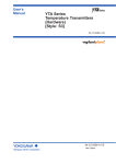
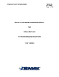
The HART communicator can interface with the
transmitter from the control room, the transmitter site,
or any other wiring termination point in the loop,
provided there is a minimum of 250W between the
connection and the power supply. To communicate, it
must be connected in parallel with the transmitter; the
connections are non-polarized. Figure 2.1 illustrates the
wiring connections for direct interface at the transmitter site for the YTA. The HART communicator can be
used for remote access from any terminal strip as well.
L=
(Cf+10,000)
65×106
–
C
(R×C)
where: L = length in feet or meters.
R = resistance in ohms, current sense
resistance plus barrier resistance.
C = cable capacitance in pF/ft or pF/m.
Cf = Maximum shunt capacitance of field
devices in pF.
Control room
Relaying
terminals
Terminal board
Distributor
YTA
HART
communicator
HART communicator
F0201.EPS
Figure 2.1 Interconnection Diagram
2.1.2 Communication Line
Requirements
Specifications for Communication Line:
Supply voltage
General use type; 16.4 to 42 V DC
Load resistance; 250 to 600Ω
(Including cable resistance)
Minimum cable size; 24 AWG,
(0.51 mm diameter)
Cable type; Single pair shielded or
multiple pair with overall shield
2-1
IM 01C50T01-01E
2. HART COMMUNICATOR OPERATION
2.2 Basic Operation of the HART Communicator (Model 275)
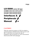
2.2.1 Keys and Functions
Communication Cable
LCD (Liquid crystal display)
(21 characters×8 lines)
Function keys
Functions of the keys are indicated on the
display.
Pressing
(HOME) when the display is
as shown changes the display to “Online”
menu. (See 2.2.2 “Display”.)
YTA :
Online
1 Device setup
2 PV
0.00 degC
3 PV AO
4.001 mA
4 PV LRV
0.00 degC
5 PV URV
100.00 degC
Moves the highlighting cursor on the display to
select the desired item.
Hot key
Call up setting menu
1. Range values
2. Chng Wrt Protect
Power ON/OFF
1. Changes the display contents.
2. Moves the position where a number or
character is to be entered.
Pressing
calls up the display
corresponding to the item pointed with the
highlighting cursor.
Pressing
returns to the previous
display. (See 2.2.3.)
Alphanumeric keys
1. Enters numbers and characters.
2. Selects the desired menu item with the
corresponding number. (See 2.2.4.)
Pressing single key enters the number.
Pressing the key with shift key enters the
alphabetic character.
(Press)
(ENTER)
Shift keys
Use to enter alphabetic characters.
To enter “7”,
‘7’
To enter “C”,
‘C’
F0202.EPS
Figure 2.2 The HART Communicator
2-2
IM 01C50T01-01E
2. HART COMMUNICATOR OPERATION
2.2.2 Display
Function Key Labels
The HART communicator searches for transmitter on
the 4 to 20 mA loop when it is turned on. When the
HART communicator is connected to the transmitter,
“Online” menu (Top menu) is started automatically
and the following display appears. If no transmitter is
found, you select “Online” menu.
Manufacturer’s transmitter type Tag (8 Characters) <a>
<b>
<c>
<d>
YTA :YOKOGAWA
Online
1 Device setup
2 PV
0.00 degC
3 PV AO
4.001 mA
4 PV LRV
0.00 degC
5 PV URV
100.00 degC
<e>
Function keys
The highlighting cursor
Pressing one of the SHIFT keys makes the arrow
mark corresponding to the pressed key appear.
Appears when the voltage level of the battery is low
F0203.EPS
Figure 2.3 Display
<a>
<b>
<c>
<d>
<e>
appears and flashes during communication
between the HART communicator and the
transmitter. In Burst mode,
appears.
The menu items selected from the previous menu.
The items to be used from the menu of <b>.
or
appears when the item is scrolled out of
the display.
The labels of function corresponding to each
function key appears. These labels reflect currently available choices.
F1
F2
F3
F4
HELP
access on-line
help
ON/OFF
activates or
deactivates a
bianry variable
ABORT
terminate
current task
OK
acknowledge
information on
screen
RETRY
try to reestablish
communication
DEL
delete current
character or Hot
Key Menu item
ESC
leave value
unchanged
ENTER
accept userentered data
EXIT
leave the
current menu
SEND
send data to
device, or mark
data to send
QUIT
terminate session
because of a
comunication
error
NEXT
leave the
current menu
YES
answer to
yes/no question
PGUP
move up one
help screen
PGDN
move down one
help screen
NO
answer to
yes/no question
ALL
include current
Hot Key item on
Hot Key Menu
for all devices
PREV
go to previous
message in a
list of messages
NEXT
go to next
message in the
list of messages
ONE
include Hot Key
item for one
device
NEXT
go to the next
variable in
offline edit
SAVE
save information
to memory
module or data
pack
HOME
go to the top
menu in the
device
description
FILTR
opens
customization
menu to sort
configurations
MARK
toggles marked
configuration
variables for
sending to field
device
BACK
go back to
menu from
which HOME
was pressed
XPAND
opens detailed
configuration
information
EDIT
edit a variable
value
CMPRS
closes detailed
configuration
information
ADD
add current item
to Hot Key
Menu
F0303.EPS
Figure 2.4 Function Key Labels
2.2.3 Calling Up Menu Addresses
Clause 3.2 shows the configuration of all menu items
available with the HART communicator. The desired
item can be displayed with ease by understanding the
menu configuration.
When the HART communicator is connected to the
transmitter, “Online” menu will be displayed after
power is turned on (See Figure 2.2). Call up the
desired item as follows:
Key operation
There are two choices to select the desired menu item.
1. Use the
or
key to select the desired item,
and then press the
key.
2. Press the number key displayed for the desired
item.
2-3
IM 01C50T01-01E
2. HART COMMUNICATOR OPERATION
• To return to the previous display, press the
* If ABORT , ESC
desired function key.
and
EXIT
2.2.4 Entering, Setting and Sending
Data
key.
are displayed, press the
The data input using the keys are stored in the HART
communicator by pressing ENTER (F4). Then, by
pressing SEND (F2), the data is sent to the transmitter.
Note that the data is not stored in the transmitter if
SEND (F2) is not pressed. All the data stored with the
HART communicator is held in memory unless power
is turned off, all data can be sent to the transmitter at
once.
Example: Call up the “Tag” to change the tag.
Check to see where item “Tag” is located in the menu
configuration. Then, call up “Tag” item on the display
according to the menu configuration.
Device setup
PV
PV AO
PV LRV
PV URV
Process variables
Diag/Service
Basic setup
Detailed setup
Review
Tag
PV Unit&Damp
Range values
.
.
.
Operation
Entering data on the “Tag” setting display.
Example: To change from Tag “YOKOGAWA” to “FIC-1A”.
YTA :YOKOGAWA
Tag
YOKOGAWA
YOKOGAWA
Call up the “Tag” setting display.
HELP
DEL
ESC
ENTER
1. Device setup
Display
Operation
3. Basic setup
1
YTA :YOKOGAWA
Online
1 Device setup
2 PV
3 PV AO
4 PV LRV
5 PV URV
DEL
SET
ESC
or
ENTER
1. Tag
YTA :YOKOGAWA
Tag
YOKOGAWA
YOKOGAWA
Display 1 appears when the HART
Communicator is turned on.
Select “Device setup”.
HELP
2
YTA :YOKOGAWA
Device setup
1 Process variables
2 Diag/Service
3 Basic setup
4 Detailed setup
5 Review
DEL
SAVE HOME ENTER
ESC
ENTER
×2
When the setting display shown above appears,
enter the data as follows:
or
Select “Basic setup”.
Character to
be entered
3
YTA :YOKOGAWA
Basic Setup
1 Tag
YOKOGAWA
2 PV Unit&Damp
3 Range values
4 Snsr 1 config
5 Snsr 2 config
HELP SAVE HOME ENTER
DEL
Operation
Display
or
F
F O K O G A W A
Select “Tag”.
I
F I K O G A W A
C
F I C O G A W A
-
F I C - G A W A
1
F I C - 1 A W A
A
F I C - 1 A W A
4
The display for Tag setting appears.
YTA :YOKOGAWA
Tag
YOKOGAWA
YOKOGAWA
HELP
DEL
ESC
ENTER
Deletes
characters.
2
F I C - 1 A
(DEL)
2-4
IM 01C50T01-01E
2. HART COMMUNICATOR OPERATION
5
Display
Operation
YTA :YOKOGAWA
Tag
YOKOGAWA
FIC-1A
(ENTER)
HELP
DEL
ESC
ENTER
After entering the data, set the
HART communicator with the data
entered by pressing ENTER (F4).
6
YTA :YOKOGAWA
Basic setup
1 Tag
FIC-1A
2 PV Unit&Damp
3 Range values
4 Snsr 1 config
5 Snsr 2 config
HELP SEND HOME ENTER
(SEND)
Send the data to the transmitter by
pressing SEND (F2).
7
YTA :FIC-1A
Basic setup
1 Tag
FIC-1A
2 PV Unit&Damp
3 Range values
4 Snsr 1 config
5 Snsr 2 config
HELP SAVE HOME ENTER
*
is flashed during communication.
SEND disappears, and the
transmission is complete.
2-5
IM 01C50T01-01E
3. OPERATION
3.
OPERATION
• Tag No., Message, Descriptor (→ 3.4.6 ,
3.5.1)
Setting data in Tag, Message, and Descriptor
parameters.
• Test Output (→ 3.5.2)
Make the transmitter output a fixed current from -2.5
through 110 % in 0.1% increments for loop checks.
• Sensor Burnout (→ 3.5.3)
Configure the current output value in sensor failure.
Selectable from High, Low and User setting value.
• Integral Indicator Display Mode (→ 3.5.4)
To change items to be displayed on the Integral
Indicator.
• Write Protection (→ 3.5.5)
To enable / disable write protection of parameters.
• Sensor Backup Function (→ 3.5.8)
To configure a transmitter to automatically transfer
the input from Sensor1 to Sensor2 when Sensor1
fails.
• Burst Mode (→ 3.5.9)
In the burst mode, a transmitter continuously sends a
selected set of data.
• Sensor trim (→ 3.5.6)
The trim adjustment function allows the user to add a
compensation to the factory set characterization
curve to more closely match the input signal.
• Output trim (→ 3.5.7)
Adjust the output value. See “IM01C50B01-01E 6.
Calibration” also.
IMPORTANT
Do not turn off the power to the transmitter
immediately after transfer of the data from HART
Communicator. If the transmitter is turned off in
less than 30 seconds after parameters has been
set, the setting data will not be stored and the
transmitter will return to the previous settings.
NOTE
Parameters and functions in regards to Sensor2
are offered only for Model YTA320, and not
available with YTA110/YTA310.
3.1 Parameter Description
The followings outline the functions of the HART
parameters for YTA. Table 3.1 shows the name, usage
and selection of each parameter.
• Review Configuration Data (→ 3.3)
• Sensor Configuration (→ 3.4.1)
When changing the sensor type from the current
setting to another, it is necessary to change some
parameter settings.
• Process variable mapping (→ 3.4.2)
Process variable is to be assigned as primary(PV),
secondary(SV), tertiary(TV) and fourth(4V) Variable
and can be monitored on the Integral indicator or
Handheld terminal. Primary variable(PV) is output as
the 4 to 20mA analog signal.
• Unit Setting (→ 3.4.3)
Choose the engineering unit for the process variables
assigned as PV,SV, TV and 4V from °C, Kelvin, °F
and °R . When mV or ohm is specified as an input
type, the unit is automatically set as mV or ohm.
• Range setting (→ 3.4.4 )
Changing the range of PV to be output as the 4 to
20mA DC. There’s two ways to set the range value.
<a> Setting by keypad
<b> Setting by applying value
• Damping time constant (→ 3.4.5)
Setting the response time of the transmitter smooths
the output with rapid changes in input.
3-1
IM 01C50T01-01E
3. OPERATION
Table 3.1 Parameters list
Item
Sensor1
Configuration
Sensor2
Configuration
(YTA320 only)
Note 1:
Note 2:
Page
Tag number, up to 8 characters
3-11
Tag Ex
Extension of Tag, up to 8 characters
3-11
Descriptor
Up to 16 characters
3-11
Message
Up to 32 characters
3-11
Date
mm/dd/yy
3-11
Sensor1(2)
snsr s/n
To describe a serial number of sensor.
0 to 16777215
—
Engineering Unit
PV units
(SV,TV,4V)
°C, K, °F, °R (Note 1)
3-8
Range
LRV/URV
Set the calibration range using the keypad.
3-9
Apply values
Value for 4 and 20 mA signal is set with actual input applied.
3-10
Damping time
constant
PV Damp
(SV,TV,4V)
Adjust the output response speed of the 4 to 20 mA DC.
Enter integer value from 0 to 99 seconds.
3-10
PV damping
holding point
PV damp point
Set the % of PV where the damping function is disabled.
When PV exceeds this value, the damping is disabled and
the output follows the PV.
Variable
mapping
PV is
(SV,TV,4V)
Specify the value to be used as PV from: “Sensor1”,
“Terminal Temperature(Term)” and “Sensor1-Term”. The SV,
TV and 4V can also be specified and monitored from the
HART communicator or Integral Indicator.
The YTA320 variables include above plus: “Sensor2”,
“Sensor2-Term”, “Average” and “Differential temperature”.
Differential
Direciton
Diff direction
(YTA320 only)
When using differential value, select whichever is desired;
Sensor1-Sensor2 or Sensor2-Sensor1.
3-8
Sensor1 type
Snsr1 Type
Specify input type.
3-5
Sensor1 wire
Snsr1 Wire
Specify the number of wire for RTD or ohm input.
3-5
Sensor1 unit
Snsr1 unit
Select a unit from °C, K, °F, or °R. (See note 1). This unit is
automatically referred as a PV, SV, TV or 4V unit when
Sensor1 is mapped.
3-5
Snsr1 Match
Enbl
Enable / disable sensor matching function. When it is set to
“enable”, sensor coefficient parameter can be entered.
3-17
Snsr1 Match
coefs
3-17
Sensor matching
function (Note 2)
Terminal
Temperature
Description
Tag
Memory
Process Variable
HART
Communicator
3-10
3-6
Terminal Temp.
unit
Term unit
Sensors specific co-efficients (by Callender vanDusen or
IEC)
Select a unit from °C, K, °F, or °R. (See note 1). This unit is
automatically referred as a PV, SV, TV or 4V unit when
Terminal Temperature is mapped.
CJC Function
CJC Select
Select CJC function
3-18
CNST CJC
Temp
Specify constant value to be used for CJC function.
3-18
Sensor2 type
Snsr2 Type
Specify input type.
3-5
Sensor2 wire
Snsr2 Wire
Specify the number of wires.
3-5
Sensor2 unit
Snsr2 unit
Sensor matching
function (Note 2)
Snsr2 Match
Enbl
Select a unit from °C, K, °F, or °R. (See note 1). This unit is
automatically referred as a PV, SV, TV or 4V unit when
Sensor2 is mapped.
Enable/disable sensor matching function. When it is set to
“enable”, sensor coefficient parameter can be set.
Snsr2 Match
coefs
Sensors specific co-efficients (by Callender vanDusen or
IEC)
3-17
Sensor Back-up
Function
Enbl Snsr Bkup
Enables/disables sensor back-up mode.
3-16
Bkup state
Shows the back-up status.
3-16
(YTA320 only)
Bkup Return
Snsr1
Enables the recovery from Sensor2 to sensor1 in back-up
operation.
3-16
°F and °R are available only when option code /D2 is specified.
The parameters are available only when option code /CM1 is specified with YTA310/YTA320.
3-2
—
3-5
3-17
T0301_1.EPS
IM 01C50T01-01E
3. OPERATION
Item
Output
Display
(Note 3)
Monitoring
Maintenance
Note 3:
Page
3-11
Show the current setting of the output direction in CPU failure
which is set by hardware switch on a CPU assembly.
Select a set of data to be continuously sent; (1)PV, (2)output
in % range & current, (3)PV and output in current.
3-11
Burst mode
Enable/disable the burst mode.
3-16
Multi-drop mode
Poll addr
Setting the polling address (0 to 15).
3-17
Display select
Process Disp,
%/mA Disp,
Err-No Disp,
Bar graph,
Matrix Disp
Select variables/information to be displayed on an integral
indicator.
Display update
period
Disp update
Select the update period form fast, normal, and slow.
Process Variable
PV,SV,TV,4V
Process variables.
—
Output in %
PV % rnge
% Output variable
—
Output in mA
PV AO
4 to 20 mA Output variable
—
Terminal
Temperature
Term
Terminal temperature variable
—
Test Output
Loop test
Used for loop checks. Output can be set from 4, 20 mA or the
designated value within 3.6 to 21.6 mA.
3-11
Self-diagnostics
Self test
Check the transmitter status. If an error is detected, the
corresponding message is displayed.
3-19
Master test
Reset the CPU of the transmitter and check the status.
—
Status
Display of the result of self-test.
3-19
Set warning enbl
Show/not show warning messages.
3-22
Error log view
Up to 4 error histories are stored in EEPROM.
3-22
Max/Min log
Maximum and Minimum value of PV, SV, TV, 4V and Terminal
Temperature during the operation.
3-22
Operate Time
Operation time from last power-up.
3-22
Snsr burnout type
Output in CPU
failure
AO Alrm typ
Burst mode
Burst option
Sensor trim
(Sensor1/2)
Analog output
trim
Referential
Information
Description
Select the output direction/value upon Sensor failure from
Low, High, off or user-setting value (mA or %).
Sensor burn-out
Output
Write Protect
Adjustment
HART
Communicator
3-16
3-12
3-13
Power Check
Unintentional power-loss during operation may be detected.
3-22
Write protect
Displays the permit/protect status for setting changes.
3-13
Enable wrt
10 min
Write protect status is released for 10 minutes when the
password is entered.
3-14
New password
Setting a new password.
3-14
Software Seal
Shows if the “joker” password has been used during the
operation.
3-14
Input trimming
mode
Select input trimming mode. The mode depends on the kind
of calibration device and the number of calibration points.
3-14
Snsr1(2) trim act
Select the action type of input trimming.
3-14
S1(2)
trim zero/gain
Input an additional compensation to the factory set
characterization curve stored in the transmitter.
3-14
D/A trim, Scaled
D/A trim
Adjust the 4 mA to 20 mA output.
Distributor
Model
Dev.id
Final asmbly num
Universal rev
Fld dev rev
Software rev
PV LSL
PV USL
Snsr1(2) LSL
Snsr1(2) USL
Snsr1(2) snsr
Term LSL
Term USL
Yokogawa
YTA110/YTA310/YTA320
3-15
—
Lower Limit for PV.
Upper Limit for PV.
Lower Limit for Sensor 1(2) input.
Upper Limit for Sensor 1(2) input.
serial number information
Lower Limit for terminal temperature.
Upper Limit for terminal temperature.
T0301_2.EPS
Appears only when Integral Indicator is specified.
3-3
IM 01C50T01-01E
3. OPERATION
3.2 Menu Tree
(Device setup)
1.Process variables
(Process Variables)
1.Variable view
1.PV
2.PV % rnge
3.PV AO
4.SV
5.TV
6.4V
7.Term
2.Diff direction
1.PV is
2.SV is
3.TV is
4.4V is
1.PV Unit
2.PV Damp
3.PV damp point
1.PV Unit&Damp
1.SV Unit
2.SV Damp
2.SV Unit&Damp
2.Variable setting
3.Max/Min log
1.Variable map
3.Unit&Damp
1.PV max/min log
2.SV max/min log
3.TV max/min log
4.4V max/min log
5.Term max/min log
6.Max/Min log Clear
3.TV Unit&Damp
1.TV Unit
2.TV Damp
4.4V Unit&Damp
1.4V Unit
2.4V Damp
5.Term Unit
(Diag/Service)
2.Diag/Service
1.Test device
1.Status
2.Self test
3.Master test
4.Set waming enbl
1.Apply values
2.Loop test
2.Range values
3.Calibration
Online Menu
1.Status group 1
2.Status group 2
3.Status group 3
4.Status group 4
5.Status group 5
6.Status group 6
1.PV LRV
2.PV URV
3.PV Unit
4.PV LSL
5.PV USL
1.Snsr 1 inp trim
1.Device setup
3.Sensor Trim
2.Snsr 2 inp trim
2.PV
3.PV AO
4.AO D/A Trim
4.PV LRV
4.Error log
1.Error log view
2.Error log clear
5.Power monitoring
1.Power Check
2.Operate Time
5.PV URV
1.D/A trim
2.Scaled D/A trim
3.D/A Clr to Default
1.Snsr1
2.Input Triming Mode
3.Sns1 Trim Act
4.S1 Trim Zero/Gain
1.Snsr2
2.Input Triming Mode
3.Sns2 Trim Act
4.S2 Trim Zero/Gain
(Basic Setup)
3.Basic setup
1.Tag
2.PV Unit&Damp
1.PV Unit
2.PV Damp
3.PV damp point
3.Range values
4.Snsr 1 config
5.Snsr 2 config
6.Snsr1 sensor s/n
7.Snsr2 sensor s/n
1.Snsr1 Type
2.Snsr1 Wire
3.Snsr1 unit
4.Snsr1 Match Enbl
1.Snsr2 Type
2.Snsr2 Wire
3.Snsr2 unit
4.Snsr2 Match Enbl
1.Snsr1
2.Snsr 1 config
3.Snsr 1 inp trim
1.Process sensor 1
4.Snsr 1 info.
2.Process sensor 2
1.Sensors
3.Term temp sensor
4.Snsr Backup
2.Signal condition
3.Output condition
4.Device information
5.Review
1.Sensor 1 Review
2.Sensor 2 Review
3.Term temp Review
1.Snsr2
2.Snsr 2 config
3.Snsr 2 inp trim
4.Snsr 2 info.
(Detailed setup)
4.Detailed setup
1.PV LRV
2.PV URV
3.PV Unit
4.PV LSL
5.PV USL
1.PV % rnge
2.PV LRV
3.PV URV
4.PV Unit&Damp
5.Apply values
6.PV LSL
7.PV USL
8.PV Min span
1.Term
2.Term Unit
3.Term temp Limits
4. CJC Select
5. CNST CJC Temp
5.Snsr burnout
1.Poll addr
2.Num req preams
3.Burst mode
4.Burst option
3.Meter output
1.Display select
1.Tag
2.Tag Ex
3.Descriptor
4.Message
5.Date
6.Final asmbly num
7.Distributor
8.Model
9.Dev id
Write protect
2.Disp Update
5.Device Review
1.Term LSL
2.Term USL
1.AO
2.AO Alrm typ
3.Loop test
4.AO D/A Trim
2.HART output
Revision #’s
1.Snsr2 snsr s/n
2.Snsr2 LSL
3.Snsr2 USL
1.Snsr Bkup
2.Bkup State
3. Bkup Return Snsr1
1.Analog output
4.Out&Meter Review
1.Snsr1 snsr s/n
2.Snsr1 LSL
3.Snsr1 USL
1.Snsr burnout type
2.Snsr burnout val
1.Process Disp
2.%/mA Disp
3.Err-No Disp
4.Bar graph
5.Matrix Disp
<Hot key>
1.Range values
2.Wrt protect menu
1.Universal rev
2.Fld dev rev
3.Software rev
Note :
Some parameters may appear or
disappear depending on the model,
suffix, option codes and setting of
parameters.
Figure 3.1 Menu Tree
3-4
IM 01C50T01-01E
3. OPERATION
3.3 Review
Before starting operation, review all the configuration
of the transmitter to confirm that it meets the current
application.
1. Device setup
Call up “Review” display.
Parameters are grouped by type
and listed in review display of each
group.
5. Review
YTA :
Review
1. Sensor 1 Review
2. Term temp Review
3. Out & Meter Review
ENTER
4. Device Review
HELP
SAVE
HOME
Call up each review display, and
scroll through the list to check each
variable.
If a change is necessary, refer to the
“3.4 Basic Setup” in this manual.
3.4 Basic Setup
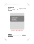
3.4.1 Sensor Configuration
When changing sensor type, it is necessary to change
the parameters related to the sensor type.
Figure 3.1 diagram shows the wire connections to the
input terminals of the transmitter and sensor type
selections for the parameters in each connection case.
Note that TCs and mV are categorized as Group A and
RTDs and ohm as Group B.
Check the connections between the input terminals and
temperature sensors and set the correct sensor type and
the number of wire connections for the parameters.
1-input model YTA110, YTA310, and YTA320
Thermocouple and DC voltage (TC & mV)
Thermocouple and DC voltage (TC & mV)
(+)
(–)
1
2
3
4
5
(+)
Sensor1
Group A
(B)
1
2
3
4
5
Group B
(B)
(B)
1
2
3
4
5
(A2)
Group B
(A)
(B)
(B)
1
2
3
4
5
(B1)
(B1)
(B2)
(B2)
(A2)
Sensor1
Sensor1
Group A
Sensor2
Group A
Sensor1
Group B
Sensor2
Group B
Resistance thermometer(RTD) and resistance (3-wire type)
(A1)
1
2
3
4
5
Sensor1
Group B
Sensor2
Group B
Thermocouple(TC) &
Resistance thermometer(RTD) and resistance (3-wire type)
Resistance thermometer(RTD) (4-wire type)
(A)
1
2
3
4
5
(B1)
(B2)
Sensor1
1
2
3
4
5
Resistance thermometer(RTD) and resistance (2-wire type)
(A1)
Sensor1
Resistance thermometer(RTD) and resistance (3-wire type)
(A)
(–)
(+)
Resistance thermometer(RTD) and resistance (2-wire type)
(A)
Group A
2-input model YTA320
(+)
Group B*
* : Without ohm
(–)
(B)
(B)
(A)
1
2
3
4
5
Sensor1
Group A
Sensor2
Group B
TYPE B (IEC584)
TYPE W3 (ASTM988)
TYPE W5 (ASTM988)
TYPE E (IEC584)
TYPE J (IEC584
TYPE K (IEC584)
TYPE L (DIN43710)
TYPE N (IEC584)
TYPE R (IEC584)
TYPE S (IEC584)
TYPE T (IEC584)
TYPE U (DIN43710)
Pt100 (IEC751)
Pt200 (IEC751)
Pt500 (IEC751)
JPt100 (JIS)
Ni120 (STI INC)
Cu (SAMA RC21-4)
ohm
mV
Group B
TYPE B (IEC584)
TYPE W3 (ASTM988)
TYPE W5 (ASTM988)
TYPE E (IEC584)
TYPE J (IEC584
TYPE K (IEC584)
TYPE L (DIN43710)
TYPE N (IEC584)
TYPE R (IEC584)
TYPE S (IEC584)
TYPE T (IEC584)
TYPE U (DIN43710)
Pt100 (IEC751)
Pt200 (IEC751)
Pt500 (IEC751)
JPt100 (JIS)
Ni120 (STI INC)
Cu (SAMA RC21-4)
ohm [* Only for 2 or 3-wire type]
mV
F0303.EPS
3-5
IM 01C50T01-01E
3. OPERATION
3
Example: To set Pt100, 4-wire sensor as “Sensor1” input.
Also set a unit for Sensor1 as “°C”.
YTA :
Snsr 1 config
1. Snsr1 Type
2. Snsr1 Wire
3. Snsr1 unit
3 Wire
deg C
Call up the “Snsr 1 config” display.
1. Device setup
HELP
HOME
ENTER
ESC
ENTER
3. Basic setup
4
4. Snsr 1 config
YTA :
Snsr1 Wire
3 Wire
2 Wire
3 Wire
4 Wire
1
YTA :
Snsr 1 config
1. Snsr1 Type
2. Snsr1 Wire
3. Snsr1 unit
HELP
SAVE
HOME
Enter “2” to call up “Snsr1 Wire”
setting display.
3 Wire
deg C
ENTER
HELP
SEND
Press “1” to call up “Snsr1 Type”
display.
Press down key until designated
wire number is high-lighted. Press
ENTER[F4].
5
YTA :
Snsr 1 config
1. Snsr1 Type
2. Snsr1 Wire
3. Snsr1 unit
2
YTA :
Snsr1 type
Pt100(IEC751)
PT100(IEC751)
PT200(IEC751)
PT500(IEC751)
JPt100(JIS)
HELP SEND ABORT ENTER
HELP
Scroll with the up/down key until
designated sensor type is highlightened. Press ENTER[F4] to set
the type.
SEND
4 Wire
deg C
HOME
ENTER
ESC
ENTER
Select “3.Snsr1 unit” to set the unit
for Sensor1.
6
YTA :
Sensor1 unit
degC
degC
Kelvin
HELP
When selecting input type from T/C or mV, the
number of the wires is automatically set to “2 Wire”. It
is not necessary to change the setting in “Snsr1 Wire”.
DEK
Use
key to scroll the list
until designated unit is highlighted.
Press ENTER[F4].
7
YTA :
Snsr 1 config
1. Snsr1 Type
2. Snsr1 Wire
3. Snsr1 unit
HELP
SEND
HOME
4 Wire
deg C
ENTER
Press SEND[F2] to transfer the
data to the transmitter.
Check that SEND disappears.
3.4.2 Process Variable Mapping
Process variable can be assigned as primary(PV),
secondary(SV), tertiary(TV) or fourth(4V) Variable
and can be monitored on Integral indicator or Handheld
terminal. The primary variable(PV) is output as a 4 to
20mA analog signal, and thus it is necessary to map
the variable as PV. Other variable can be left as “Not
Used” when they are not required.
Configuration of Sensor 1 (and Sensor 2 for YTA320)
must be done before changing the process variable
mapping. (See 3.4.1)
3-6
IM 01C50T01-01E
3. OPERATION
1. Device setup
NOTE
Calling up the “Variable map”
display.
1. Process Variables
Sensor type “Non-sntandard 1” “Non-standard 2”
are always shown, but cannot be used unless a
necessary function is pre-installed in the transmitters upon shipment.
2. Variable setting
1. Variable map
1
YTA :
PV is Snsr1
SV is Term
TV is Not used
4V is Not used
Pressing 'OK' to change
them.
HELP SAVE ABORT
OK
NOTE
The display in the left shows the
current setting of the map.
Press OK[F4].
1. When SV, TV or 4V are not required, it is
recommended to leave them as “Not used”
to improve the performance.
2. Each process variable, for example “Sensor1”,
can be assigned to only one variable. If
“Sensor1” is already set as PV, it cannot be
set as SV, TV or 4V simultaneously.
4. When “Diff”, “Avg”, “Snsr1-Trem”, or “Snsr2Trem” are selected, the sensor types to be
set for Sensor1 and Sensor2 should be
selected from any one of the following three
groups; Temperature sensor(T/C and RTD),
DC voltage or resistance. The combination(for
example, temperature sensor and DC voltage
input) would cause an incorrect computation
due to the different unit system and is not
allowed.
5. When “Snsr1-Trem” or “Snsr2-Trem” are
selected, DC voltage and resistance input
should not be set for Sensor1 or Sensor2.
2
YTA :
PV is
Snsr1
Snsr1
Snsr1-Term
Term
HELP
SEND
ABORT ENTER
Scroll with the up/down key until
the designated sensor type is highlightened. Press ENTER[F4] to
set the type. The selection is as
follows.
[For YTA110, YTA310]
Sensor1
Sensor1 - Terminal Temperature
Terminal Temperature
[For YTA320]
Above plus ;
Sensor2
Sensor2 - Terminal Temperature
Diff : Sensor2-Sensor1 or
Sensor1-Sensor2
Average : (Sensor1+Sensor2)/2
3
YTA :
SV is
Not used
Snsr1
Snsr1-Term
Term
Not used
HELP SEND ABORT ENTER
Follow the same procedures for
SV, TV and 4V. When you want to
leave the setting as it is, just press
ENTER [F4] to move to the next
variable display. Pressing
ABORT[F3] will cancel all the
previous procedures for mapping.
4
YTA :
PV is Snsr1
SV is Term
TV is Not used
4V is Not used
Pressing 'OK' will
send them.
HELP SEND ABORT
OK
Press OK[F4] to send the new
setting to the transmitter.
3-7
IM 01C50T01-01E
3. OPERATION
3.4.3 Unit
— Differential Direction — (For YTA320)
If “Diff” is selected as Process variables, it is necessary
to set which is designated; Sensor1-Sensor2 or Sensor2-Sensor1.
The unit for PV is set at the factory before shipment.
When Sensor1(or Sensor2) or Terminal temperature is
mapped as PV, SV, TV or 4V, the unit that is selected
for Sensor1(orSensor2) or Terminal temperature is
automatically referred as a unit for these process
variables. (See 3.4.1 Sensor Configuration) When
another value is mapped as PV, SV, TV or 4V, it is
possible to set an independent unit for those variables.
1
YTA :
Variable setting
1 Variable map
2 Diff direction
3 Unit&Damp
HELP
SAVE
HOME
ENTER
Eneter “2” to select Differential
direction.
Example: To change the PV unit from “°C” to “°F”.
2
* “F” degree appears only when /D2 code is specified.
YTA :
Diff direction
Snsr1-Snsr2
Snsr1-Snsr2
Snsr2-Snsr1
HELP
SEND
ESC
1
ENTER
YTA
Hot
1.
2.
Press up/down key to select the
differentical direction.Press
ENTER[F4].
HELP
3
SEND
HOME
DEL
ESC
ENTER
Press Hot key and select “1. Range
values”.
YTA :
Variable setting
1 Variable map
2 Diff direction
3 Unit&Damp
HELP
:
key
Range values
Chng Wrt Protect
2
ENTER
YTA :
Range
1 PV
2 PV
3 PV
4 PV
5 PV
HELP
Press SEND[F2] to transfer the
data to the transmitter.
Check that SEND disappears.
values
LRV
0.00 degC
URV
100.00 degC
Unit
degC
LSL
-200.00 degC
USL
850.00 degC
DEL
ESC ENTER
Select the “3. PV Unit” to set the
unit.
3
YTA :
Snsr1 unit
degC
degC
degF
degR
Kelvin
HELP
DEL
ESC
ENTER
Select designated unit and press
ENTER[F4].
4
YTA :
Range
1 PV
2 PV
3 PV
4 PV
5 PV
HELP
values
LRV
0.00 degC
URV
100.00 degC
Unit
degF
LSL
-200.00 degC
USL
850.00 degC
SEND
ESC ENTER
Press SEND[F2] to send the new
setting to the transmitter.
5
YTA :
Hot key
1 PV LRV
2 PV URV
3 PV Unit
4 PV LSL
5 PV USL
HELP SEND
Check that
SEND
dissappears.
32.00 degF
212.00 degF
degF
-328 degF
1562 degF
ESC ENTER
The unit for SV, TV and 4V can be changed in
“Unit&Damping” display. Call up “Unit&Damp”
display. (1. Device setup → 1. Process variables → 2.
Variable setting → Unit&Damp.)
3-8
IM 01C50T01-01E
3. OPERATION
3.4.4 PV Range
NOTE
The range for PV corresponding to the 4 to 20mA
output signal is set at the factory before shipment.
Following are the procedures to change the range.
It is possible to set LRV>URV. This setting
reverses the 4 to 20 mA output signal.
Setting Conditions:
LSL <= LRV <= USL
LSL <= URV <= USL
|URV – LRV| >= Recom
mended Min. span
Example: To change the range from “0 to 100 °C” to
“50 to 200 °C”.
(1) Changing the range with Keypad
– LRV, URV –
1
YTA
Hot
1.
2.
:
key
Range values
Chng Wrt Protect
HELP
SAVE
ESC
ENTER
Press Hot key and call up “Range
values”.
2
YTA :
Range
1 PV
2 PV
3 PV
4 PV
5 PV
HELP
values
LRV
0.00 degC
URV
100.00 degC
Unit
degC
LSL
-200.00 degC
USL
850.00 degC
DEL
ESC ENTER
3
Select the “1. PV LRV” to set the
Lower Range Value.
Setting limit dependig on the
selected sensor type is shown as
“4. PV LSL.” And “5. PV USL”.
YTA :
LRV
0.0 degC
50.0
HELP
DEL
ESC
ENTER
Enter “50”, and press ENTER[F4].
4
YTA :
Range
1 PV
2 PV
3 PV
4 PV
5 PV
HELP
values
LRV
50.00 degC
URV
100.00 degC
Unit
degC
LSL
-200.00 degC
USL
850.00 degC
SEND
ESC ENTER
To set the Upper Range Value,
select the “2 PV URV”.
Setting limit is shown as “4 PV
LSL” and “5 PV USL”.
5
YTA :
URV
100.00 degC
200
HELP
DEL
ESC
ENTER
Enter “200” , and press ENTER[F4].
6
YTA :
Range
1 PV
2 PV
3 PV
4 PV
5 PV
HELP
values
LRV
50.00
URV
200.00
Unit
LSL
-200.00
USL
850.00
SEND
degC
degC
degC
degC
degC
Press SEND[F2] to send the new
range value to the transmitter.
Confirm that SEND disappears.
3-9
IM 01C50T01-01E
3. OPERATION
3.4.5 Damping Time Constant
(2) Changing the range while applying an
actual input – Apply values –
This feature allows the lower and upper range
values to be setup automatically with the actual
input applied.
1. Device setup
Setting the response time of each Process Variable to
make it vary slowly with a rapid change in input. Set
the value from 0 to 99 seconds.
If the time constant is set to 2 seconds, Transmitter
calculates a reading every cycle time using the damping equation, to make the output 63 percent of the
input range after 2 seconds.
Call up “Apply Values” display.
2. Diag/Service
3. Calibration
This damping time constant is normally set to work
when the temperature makes a step change within 2
percent of the output range. The damping can be
changed using the “PV damp point” parameter .
1. Apply values
1
YTA:
WARN-Loop should be
removed from
automatic control
HELP
SAVE
ABORT
OK
Example: To set the damping time constant for PV to “5”
seconds.
Press OK[F4] to make the control
loop manual.
1. Device setup
2
YTA
Set
1
2
3
:
the:
4mA
20mA
Exit
HELP
SEND
Call up “PV Unit&Damp” display.
1. Process variables
2. Variable setting
ABORT ENTER
To set the lower range value, select
“1. 4mA” and press ENTER[F4].
Unit & Damp
1. PV Unit&Damp
3
1
YTA :
Apply new 4ma input
HELP
SEND
ABORT
OK
Apply the input which corresponds
to 4mA. After obtaining stable input,
press OK[F4].
YTA :
PV Unit&Damp
1 PV Unit
2 PV Damp
3 PV damp point
degC
2 s
2 %
HELP
ENTER
SAVE
HOME
Enter “2” to call up “PV damp”
display.
4
YTA :
Current applied
process value:50.10 degC
1 Set as 4mA value
2 Read new value
3 Leave as found
HELP
SEND
ABORT ENTER
5
YTA
Set
1
2
3
2
YTA :
Snsr1 damp
2 s
5
The LRV to be changed is 50.10
degC.
• Selecting item 1 sets LRV to
50.10degC.
• Selecting item 2 reads LRV
again.
To set LRV to “50.10”, select item 1
and press ENTER[F4].
HELP
SEND
ABORT ENTER
Enter new value, and press
ENTER[F4].
3
:
the:
4mA
20mA
Exit
HELP
SAVE
ABORT ENTER
YTA :
PV Unit&Damp
1 PV Unit
2 PV Damp
3 PV damp point
degC
5 s
2 %
HELP
ENTER
SEND
HOME
Press SEND[F2] to send the
setting to the transmitter.
Check that SEND disappears.
# When necessary, change the
setting of “PV damp point”.
Select “2. 20mA” and press
ENTER[F4]. Apply the value which
corresponding to 20mA and enter it
as URV. (Refer to procedures 3
and 4 .)
After completing the range change,
select “3.Exit” and press ENTER[F4].
3-10
IM 01C50T01-01E
3. OPERATION
3.4.6 Tag No.
CAUTION
To change the Tag, see section 2.2.4 “Entering, setting
and Sending Data”.
1. Test output is held for approximately 10
minutes, and then released automatically
after the time has elapsed. If the HART
communicator power supply is turned off or
communication connector is disconnected
during the test output operation, it is held for
approximately 10 minutes.
key to release the test output
2. Press the
immediately.
Up to 8 characters can be set with “Tag”.
Example: To change from Tag “YOKOGAWA” to “FIC-1A.”
1. Device setup
Call up the “Tag” setting display.
3. Basic Setup
1. Tag
Enter new setting and press
ENTER[F4].
YTA :YOKOGAWA
Tag No.
YOKOGAWA
YOKOGAWA
NOTE
HELP
DEL
ESC
ENTER
If the transmitter is equipped with the integral
indicator, the LCD displays F.O.
See Section 2.2.4.
"F.O." lit on.
3.5 Detailed Setup
3.5.1 Device Information
F0304.EPS
Following Device information can be entered.
Tag :
Tag Extension:
Descriptor:
Message:
Date:
3.5.3 Burnout Function
Up to 8 characters.
Extension of Tag description. Up
to 8 characters.
Up to 16 characters
Up to 32 characters
mm/dd/yy mm:month, dd:day,
yy:year
a) Sensor burnout
Configure the burnout mode in the case of sensor
failure or disconnection.
Call up the “Snsr burnout type” display. [1.Device
setup → 4.Detailed setup → 3.Output condition →
1.Analog output → 5.Snsr burnout ]
When the sensor failure is detected, the transmitter
outputs one of the following values.
Low:
Outputs 3.6mA
High:
Outputs 21.6mA
User(mA): Outputs user set value in mA. Settable
within 3.6 to 21.6 mA.
User(%):
Outputs user set value in %. Settable
within -2.5 to 110 %.
Off:
The burn out output is NOT defined
Call up the “Device Information” display. [1.Device
setup → 4.Detailed setup → 4.Device information]
3.5.2 Test Output
This feature can be used to output a fixed current from
3.6 mA (-2.5%) to 21.6 mA (110%) for loop checks.
Call up the “Loop test ” display. [1.Device setup.→
2.Diag/Service → 2.Loop test]
Put the control loop in manual mode by pressing
OK[F4]. The following output selections are offered.
4mA:
20 mA:
Other:
End:
NOTE
Outputs 4 mA current
Outputs 20 mA current
Sets a desired output in mA using
alphanumeric keys.
Exits
When sensor burnout is set to “off”, the
transmitter's output will go undefined at sensor
failure. It is necessary to understand this point
well when setting “off”.
3-11
IM 01C50T01-01E
3. OPERATION
During sensor burn out time, the Sensor1 failure or the
Sensor2 failure error message is generated. (See
Section 3.6.1 for details.)
process variable is lit. If
“Inhibit” is selected, no process
variable is displayed.
If the transmitter is equipped with the integral indicator, the LCD displays “Abn.” as shown in Figure 3.2.
(b) % /mA Disp
To Specify output value to be
shown on the digital display.
Select from following;
mA
%
mA, %
Inhibit
If two values are selected, they
will appear on the display one
after another. Process variables
and output value(see (a)) is
shown on the digital display in
turn. The unit corresponding to
each output value is lit. If
“Inhibit” is selected, no ourput
value will be displayed.
Displays "Abn."
Displays output value.
F0306.EPS
Figure 3.2 Integral Indicator Display in Sensor
Burn Out
F03542
b) Burnout in hardware failure
The output status of the transmitter in hardware
failure is set using a jumper on the CPU assembly.
The current setting can be checked in parameter
“AO Alrm type”.
Call up the “AO Alrm type parameter” display.
[1.Device setup → 4.Detailed setup → 3.Output
condition → 1.Analog output → 2.AO Alrm typ].
3.5.4 Integral Indicator Display Mode
When an integral indicator is specified with the
transmitter, the display items and update speed can be
configured.
Call up the”Meter output” display [1.Device setup →
4.Detailed setup → 3.Output condition → 3.Meter
output ]
Displays PV value.
F03541
Displays bar graph.
1) Display selection
(a) Process Disp
To Specify process variables to
be shown on the digital display.
Process variables and output
value(see (b)) are shown on the
digital display in turn. Selectable from followings;
PV
SV
TV
4V
PV, SV
PV, SV, TV
PV, SV, TV, 4V
Inhibit
If two or more variables are
specified, each value appears
one after another in order. The
unit corresponding to each
F03542
Displays PV value and
sensor type
F03543
3-12
(c) Err-No Disp
To Select whether error codes
are shown on the digital display
or not when an error occurs.
When “Show” is selected, error
code will be shown on the
digital display. When “Inhibit”
is selected, no error code will
be shown on the digital display.
(d) Bar graph
To select whether the output
bar-graph display is lit or not.
When “Show” is selected, The
output value is shown in a 32segment bar-graph. If “Inhibit”
is selected, the bar-graph is off.
(e) Matrix Disp
To select information to be
shown on the dot matrix
display.
Process:Display name of the
process variable shown on
the digital display. (Ex.
PV)
Type:
Display type of the input
sensor
Wire:
Display the number of
wires of the input sensor.
IM 01C50T01-01E
3. OPERATION
3.5.5.2 Hardware Write Protect Function
Process, Type:
Display Process Variable
name and Sensor Type in
turn.
Type, Wire:
Display Sensor Type and
the number of wires in
turn
Inhibit: Display none.
Hardware write protect function is set up by Switch
(SW2) on the CPU assembly.
Pin position of SW2
Write Protect Status
WP
Y
No
SW2
N
WP
2) Disp Update
Update period of the display is
selected from Normal, Fast and
Slow.
Y
Yes
SW2
N
SW1
Burnout output direction
upon hardware failure
NOTE
When the transmitter is used at temperatures
under -10 °C, the response speed of the display
may become slow. It is recommended to set the
display speed to normal or slow in such case.
SW2
Hardware Write Protect
CPU Assembly
3.5.5 Write Protect
F0355.EPS
Figure 3.3 SW2 setting
The write protect function is used to prevent unauthorized configuration data changes in the transmitter.
There are two ways to set this function; by hardwared
and by software, and hardware write protect function is
given priority.
NOTE
1. Turn off the power supply before changing
the setting of SW2.
2. To change the SW2, it is necessary to
remove the LCD assembly with LCD model.
Refer to “ 6.3 Disassembly and Assembly” in
“YTA series Hardware Instruction Manual”
about the procedures.
Press Hot key and select “2. Wrt protect menu.”
Current status is shown in “1. Write protect.”
3.5.5.1 Write Protect Status
Press Hot key and select “2.Wrt protect menu.”
Current status is shown in “1.Write protect.”
Yes: Hardware or software write protect function
is activated. Under this status, any change
operation is denied with the message. [ In
write protect mode ] .
No : Neither protect function is activated.
3-13
IM 01C50T01-01E
3. OPERATION
3.5.5.3 Software Write Protect Function
3.5.6 Sensor Trim
●
1.
2.
3.
Each YTA transmitter is factory-characterized based on
the standard sensor curve, and uses this information to
produce a process variable output. The sensor trim
function is used to make an adjustment to the internal
interpretation of the input signal and the factory
characterization in the transmitter. (See Figure 3.4)
To activate write protect function
Press Hot key and select “2. Wrt protect menu”.
Select “3.New password”.
Enter up to 8 alphanumeric string from key-pads.
Press ENTER[F4].
4. Re enter the strings and press ENTER[F4].
5. Press OK[F4] to set the password. The status is
changed to “Write protect YES”.
Output
● To change the password or to release the
write protect mode
1. Press Hot key and select “2. Wrt protect menu” .
2. Select “2. Enable wrt 10 min”. Enter the password.
By this operation, the write protection is released
for 10 minutes. It is possible to change the
paramters.
3. Select “3.New password”.
4. To change the password, enter new password and
press ENTER[F4].
To release the write protect mode, enter 8 spaces in
the new password field and press ENTER[F4].
5. Press OK[F4] to set the new password or to release
the write protect mode.
Output
Since the factory characterization is kept even after
applying the trim operation, it is possible to ignore the
trim function when the original settings are recovered.
ZERO
GAIN
ZERO
Input
Input
One point trim
Two point trim
F0307.EPS
Figure 3.4 Trim function images
● The Procedures (For Sensor 1)
Before performing the sensor trim, complete the
configuration of the sensor input. (See 3.4.1-2)
NOTE
1. Connect the calibration device to the transmitter.
a. Wiring of power supply and output
1. “Enable Wrt 10 min” releases write protect
status for 10 minutes. While write protect is
released, enter a new password in the “New
Password” field. It will not be possible to set a
new password after 10 minutes have elapsed.
2. “Joker Password” and “Software Seal”
When you foget the password that has been
registered, it is possible to release the mode
for 10 minutes by using a joker password.
Enter YOKOGAWA to release write protect
status for 10 minutes. If this joker password is
used, the status shown in the parameter
“Software seal” is changed from “Keep” to
“Break”. Press Hot key and select “2. Wrt
Protect menu” . Current status is shown in “4.
Software seal”. This status will be returned
from “Break” to “Keep” by registering a new
password.
+ Output signal
–
Load resistance
Voltmeter
b. Example of wiring of thermocouple
or DC voltage input (1-input type)
1
2
3
4
5
(+)
(–)
DC voltage generator or
thermocouple
c. Example of wiring of thermometer resistor
4-wire type (1-input type)
1
2
3
4
5
(A)
(A)
(B)
(B)
Variable resistor or
thermometer resistor
F0305.EPS
Figure 3.5 Example of wiring for calibration
equipment
3-14
IM 01C50T01-01E
3. OPERATION
2. Call up the “Snsr1 inp trim” display. [1.Device
setup → 2. Diag/Service → 3.Calibration →
3.Sensor Trim → 1.Snsr 1 inp trim]
3. Select “2.Input Trimming Mode”. The following
selections are offered.
V.R. / ZERO&GAIN
V.R. / ZERO
Temp / ZERO&GAIN
Temp / ZERO
Select “V.R. / ZERO&GAIN” or “V.R. / ZERO”
when the calibration device is DC voltage generator
or Variable resistor or select “TEMP /
ZERO&GAIN” or “TEMP / ZERO” when the
device is Temperature sensor.
4. Enable the user trim. Select “3. Snsr1 Trim Act”.
The following selections are offered.
On:
Use User trim value
Off: Ignore User trim value, and return to the
factory setting.
Clear: Clear User trim value and return to the
factory setting.
Select “On” to enable trim function and Press
ENTER[F4].
5. Perform zero-adjustment. Call up the “4. S1 Trim
Zero/Gain”.
(a) When the input trimming mode is “V.R. /
ZERO&GAIN” or “V.R. / ZERO”, apply the value
for the zero-point shown in the table 3.2 depending
on the specified sensor type. Wait until the input
from the calibration device becomes stable.
(b) When the input trimming mode is “TEMP /
ZERO&GAIN” or “TEMP / ZERO”, expose the
temperature sensor to calibration temperature for
the zero-point. Wait until the input from the
temperature sensor becomes stable.
Perform the following steps when the input trimming mode is “V.R. / ZERO&GAIN” or “Temp /
ZERO&GAIN”.
8. Perform gain-point adjustment.
(a) When the input trimming mode is “V.R. /
ZERO&GAIN”, apply the value for the gain-point
shown in the table 3.2 depending on the specified
sensor type. Wait until the input from the calibration device becomes stable.
(b) When the input trimming mode is “Temp /
ZERO&GAIN”, expose the temperature sensor to
calibration temperature for the gain-point. Wait
until the input from the temperature sensor becomes
stable.
9. Press OK[F4].
10. Enter Gain trim reference value from key pad, and
press ENTER[F4].
Follow outlined procedures to perform Sensor2 trim.
3.5.7 Analog Output Trim
Fine output adjustment is performed with “D/A trim”
or “Scaled D/A trim”.
● D/A Trim
D/A trim is to be performed if the digital ammeter used
for calibration does not read 4.000mA and 20.000mA
exactly when the output signal is 0% and 100%.
Procedures
1. Call up the “D/A trim” display. [1.Device setup →
2. Diag/Service → 3.Calibration → 4.AO D/A Trim
→ 1.D/A trim]
2. Press OK[F4] to set the transmitter to manual
mode.
3. Connect the ammeter(±1µA is measurable) and
press OK[F4].
4. Press OK[F4] to make the transmitter output 4
mA(0%) . Check the reading of the ammeter, and
enter this value using the key pad and Press
ENTER[F4].
5. Next, press OK[F4] to make the transmitter output
20 mA (100%) . Check the reading on the ammeter,
and enter this value using the key pad.
6. After completing the above steps, return the
transmitter to automatic control.
Table 3.2
Sensor type
TC, mV
RTD, ohm
0 mV
E,J,K,N,W3,W5,L,U,mV
0 mV
Pt100, JPt100, Ni120, Cu
40 Ω
Pt200, Pt500, ohm
40 Ω
Sensor type
TC, mV
RTD, ohm
Zero-point value
B,R,S,T
Gain-point value
B,R,S,T
25 mV
E,J,K,N,W3,W5,L,U,mV
75 mV
Pt100, JPt100, Ni120, Cu
330 Ω
Pt200, Pt500, ohm
1600 Ω
● Scaled D/A trim
Scaled D/A trim can be performed to adjust the output
when using a voltmeter or the other meters scaled to 0
to 100 %.
T0302.EPS
6. Press OK[F4].
7. Enter Zero trim reference value from key pad, and
press ENTER[F4].
3-15
IM 01C50T01-01E
3. OPERATION
● To enable Sensor backup function
1. Set the sensor type, wire and unit for Sensor1 and
2. (See 3.4.1)
Any Sensor type except “Non-connection” can be
selected.
2. Map Sensor1 as PV, and Sensor2 as SV. (See
3.4.2)
TV and 4V can be set to any designated value
except for “Sensor1” and “Sensor2” from the
selection. Sets damping time constant and unit for
each process variable.
3. Set the sensor burnout type to High, Low or user
setting value.
If the sensor burnout type is set to "off", the sensor
failure will not be detected and the backup function
will not act.
4. Send all the setting data to a transmitter.
5. Call up the “Snsr Backup” display. [1.Device setup
→ 4.Detailed Setup → 1.Sensors → 4.Snsr Backup
→ 1.Snsr Bkup]
6. Select Sensor Backup “Enable”. Press ENTER[F4] .
Example: To adjust using a voltmeter.
Procedures
1. Call up the “Scaled D/A trim” display. [1.Device
setup → 2.Diag/Service → 3.Calibration → 4.AO
D/A Trim → 2.Scaled D/A trim]
2. Press OK[F4] to set the transmitter to manual mode .
3. Select “2. Change” and press ENTER[F4].
4. Enter the value read on the meter when the signal is
4 mA. In this case, enter the value of the voltage
across the 250Ω resistor (1V) and press
ENTER[F4].
5. Enter the value read on the meter when the signal is
20 mA. In this case, enter the value of the voltage
across the 250Ω resistor (5V) and press
ENTER[F4].
6. Select “1. Proceed” and press ENTER[F4].
7. Connect voltmeter and press ENTER[F4].
8. Press OK[F4] to make the transmitter output 4
mA(0%) . Check the reading on the voltmeter, and
enter this value using the key pad.
9. Next, press OK[F4] to make the transmitter output
20 mA (100%) . Check the reading on the voltmeter, and enter this value using the key pad.
10. After completing the above steps, return the
transmitter to automatic control.
● To make the transmitter return to using
Sensor1 in Backup Operation
1. Confirm that the Sensor1 is recovered
2. Call up the “Bkup Return Snsr1” parameter.
[1.Device setup → 4.Detailed Setup → 1.Sensors
→ 4.Snsr Backup → 3.Bkup Return Snsr1]
3. Press OK[F4]. Backup status returns to “Waiting.”
3.5.8 Sensor Backup (For Model
YTA320 only)
NOTE
The sensor backup command sets the transmitter to
automatically use Sensor2 as output if Sensor1 fails.
When the sensor backup mode is activated, the
transmitter will output the Sensor1 which is mapped as
PV. Sensor2 is mapped as SV. If sensor1 fails, the
transmitter starts Sensor Backup operation and
Sensor2(SV) is output in place of PV. There’s no
disruption in 4 to 20 mA output. The Error code for
sensor1 failure is shown on an Integral Indicator, if it
is specified. Error message is sent to the HART
communicator that the sensor1 failed and the sensor
backup mode has started. In backup operation, even if
the Sensor1 recovers, the transmitter will continue to
use Sensor2 until the backup operation is reset by
parameter or power is turned off. If Sensor2 fails
during backup operation, the transmitter will send an
error code for Sensor2 failure to the Integral Indicator
and HART communicator and output the “Sensor
burnout” value.
Don’t change the sensor type, wire and setting
of PV and SV while Sensor Backup mode is
“Enable.” When the change is necessary, turn
Sensor Backup mode “Disable” before changing.
3.5.9 Burst Mode
The transmitter continuously sends the data stored in it
when the burst mode is set ON. The data is sent
intermittently as a digital signal with 75ms intervals
when the transmitter is set in the burst mode. Therefore, communications with the HART communicator is
also possible.
Any one of the following values can be selected.
PV
% range/current:
Process vars/ crnt:
3-16
Output in % and mA
Output in mA and Process
variables (PV, SV, TV and
4V)
IM 01C50T01-01E
3. OPERATION
3.5.11 Sensor Matching Function
1. Call up the “HART output” display. [1.Device
setup → 4.Detailed setup → 3.Output condition →
2.HART output]
2. Select “4. Burst option”. Select a set of data to be
sent.
3. Return to “HART output” display and select “3.
Burst mode”. Select “On” to start the burst option.
Press SEND[F2] to send the setting. To release the
burst mode, select “Off” in this display.
This function is available only when optional specification /CM1 is specified with YTA310 or YTA320.
Siginificant temperature measurement accuracy
improvement can be obtained using a temperature
sensor that is matched to a transmitter. This matching
process entails teaching the transmitter the relationship
between resistance and temperature for a specific RTD
sensor. This relationship, approximated by the
Callender-van Dusen equation, is described as following :
If the transmitter is equipped with the integral indicator, the LCD displays “B.M.”
Rt = R0 {1 + α (1+0.01δ ) t - αδ / 104 t2 - αβ / 108
(t -100 ) t3 }
3.5.10 Multi Drop
“Multi dropping” transmitters refers to the connection
of several transmitters to a single communication
transmission line. Up to 15 transmitters can be connected when set in the multidrop mode. To activate
multi drop communication, the transmitter address
must be changed to a number from 1 to 15. This
change deactivates the 4 to 20 mA analog output,
sending it to 4mA . The alarm current is also disabled.
where : Rt = Resistance (ohms) at
Tempearature t (oC)
R0 = Sensor -specific constant
(Resistance at t=0 oC)
α (alpha) = Sensor-specific constant
δ (delta) = Sensor-specific constant
β (beta) = Sensor-specific constant
(0 at t>0 oC)
● Setting of Multi drop
Call up the “HART output” display. [1.Device
setup → 4.Detailed setup → 3.Output condition →
2.HART output]
Select “1. Poll addr” and set the polling address.(a
number from 1 to 15).
Press SEND[F2] to send the setting.
Although the sensor curve is standardized, the exact
values for R0, α, δ and β are specific to each RTD
sensor and are obtained by testing each individual
sensor at various temperatures. These constants are
known as Callender-van Dusen constants.
Generally, the constants R0, A, B, and C are also used
as the characteristic coefficients of the RTD instead of
R0, α, δ and β. These are derived from IEC Standard
Curve and the relationship is described as followings ;
If the transmitter is equipped with the integral indicator, the LCD displays “M.D.” and "F.O."
Rt = R0 {1 + At - Bt2 + C (t -100) t3 }
NOTE
where : Rt = Resistance (ohms) at
Tempearature t (oC)
R0 = Sensor-specific constant
(Resistance at t=0 oC)
A = Sensor-specific constant
B = Sensor-specific constant
C =Sensor-specific constant
(0 at t > 0 oC)
1. When the identical address is set for two or
more transmitters in multidrop mode, communication with these transmitters is disabled.
2. Multi drop mode and Burst mode should not
be operated together at the same time.
● Releasing the Multidrop mode
First, call up the “HART output” display. [1.Device
setup → 4.Detailed setup → 3.Output condition →
2.HART output]
Select “1. Poll addr” and set the polling address to
“0”. Press SEND[F2].
These two equations are equivalent. A model YTA
can cope with either case as above-mentioned.
3-17
IM 01C50T01-01E
3. OPERATION
● For Setting up two sensors (For model
YTA320 )
If using two sensors with a model YTA320, repeat the
procedures for the Sensor2. [1. Device setup
→ 3. Basic setup → 5. Snsr 2 config ]
NOTE
1. This function is effective only in three kinds of
sensors; Pt100, Pt200 and Pt500.
2. Input relations between the sensor type and
the value of R0 properly. When Pt100 is
specified as an input type, the value close to
100 must be set to R0. When Pt500 is
specified as an input type, the value close to
500 must be set to R0.
3. When the sensor type is changed, the sensor
matching function must be set up again or set
to “Disable”.
Table 3-3
Item
Initial Setting Value
R0
IEC
Callender
vanDusen
100
A
3.9083 E-3
B
-5.775 E-7
C
-4.183 E-12
α
3.8506 E-3
δ
1.4998
β
● Setting the Sensor Matching Function (by
using alpha delta and beta co-effieicent)
1. Set the designated sensor type and the number of
wires. (Refer to “3.4.1 Sensor Configuration” in
this manual. )
2. Call up the “Snsr1 Match Enbl” display.
[1.Device setup → 3. Basic setup
→ 4. Snsr1 config → 4. Snsr1 Match Enbl ]
3. Select “Enable” and press ENTER[F4].
4. Call up the “Snsr1 Match coefs” display.
[1. Device setup → 3. Basic setup → 4. Snsr1 config
→ 5. Snsr1 Match coefs ]
5. Select “2. alpha delta beta” and press ENTER[F4] .
6. The display shows the current setting of the R0,
alpha, delta, and beta values. Press OK[F4] .
7. The communicator prompts you to enter R0, alpha,
delta and beta value successively. Enter the R0,
alpha, delta and beta values and press ENTER[F4]
accordingly.
8. Press OK[F4] to confirm the new values.
9. Press SEND[F2] to transfer the data to the transmitter. Check that [SEND] dissappears.
Note : “E-3” stands for 10
1.0863 E-1
-3
T0303.EPS
3.5.12 CJC Selection
For thermocouple input, the terminal temperature
measured by an internal sensor is used for Cold
Junction Compensation function. In YTA, constant
value set by users can be used for the compensation
function in place of the measured terminal temperature.
If the constant value is set to “0”, compensation will
not be applied.
1. Call up the parameter “CJC Select” . [1.Device
setup → 4. Detailed setup → 1. Sensors → 3. Term
temp sensor → 4. CJC Select ]
2. Select “Constant CJC” and press ENTER[F4].
3. Call up the parameter “CNST CJC Temp” .
[1.Device setup → 4. Detailed setup → 1. Sensors
→ 3. Term temp sensor → 5. CNST CJC Temp
4. Enter temperature value in constant and press
ENTER[F4].
3.6 Self-Diagnostics
When “Disable” is selected in the above step 3,
temperature is calculated by using the default value of
R0, alpha, delta and beta.
3.6.1 Checking for Problems
(1) Identifying Problems with the HART Communicator
Self diagnostics of the transmitter and check of
incorrect data settings can be carried out with the
HART communicator. There are two methods for selfdiagnosis of the transmitter; self-diagnosis for every
transmission and manually executing the Self test
command.
● Setting up the Sensor Matching Function
(by using A,B and C co-effieicent)
If using the R0, A,B and C parameters in place of
alpha delta and bata co-efficients, replace “2. alpha
delta beta” with “1. A B C” in the step 5 in the above.
In YTA series, there're two classes to show the result
of diagnostices; errors and warnings. Errors are the
serious status for operation which must be corrected
3-18
IM 01C50T01-01E
3. OPERATION
iimmediately. Warnings are the light errors and
indication of the status which is important for operation.
When an error message appears, see table 3.4 “List of
Errors” for details. If warning messages are set be
shown, the warning status will also be shown on the
HART communicator. See table 3.5 “List of Warnings”
for details.
Diagnostic by “Self test”
1. Device setup
2. Diag/Service
1. Test device
1
YTA :
Test device
1 Status
2 Self test
3 Master test
4 Set warning enbl
HELP
SAVE
HOME
Call up the “Test device” display,
and select “Self test”.
ENTER
2
YTA :
Self test OK
HELP
SAVE
OK
ABORT
OK
If there is no error detected, “Self
test OK” will be displayed. When an
error occurs, an error message
appears, and the results of selfdiagnosis appears in the Status item.
3
Call up the “1. Status”.
YTA :
Test device
1 Status
2 Self test
3 Master test
4 Set warning enbl
HELP
SAVE
HOME
ENTER
YTA :
Status
1 Status group 1
2 Status group 2
3 Status group 3
4 Status group 4
5 Status group 5
HELP SAVE HOME
ENTER
4
The Error status is in groups 1 and
2.
The Warning status is in groups 3
through 6. Highlight the group to
show the status Errors. If Error is
not detected, the result of
diagnostics is indicated as “OFF”.
If “ON” is indicated, a
countermeasure for that error is
necessary.
NOTE
Note that if the Set warning enbl is set to “OFF
(not display)”, the status in this display remains
“ OFF ” even when the warning status occurs.
(See 3.6.2)
3-19
IM 01C50T01-01E
3. OPERATION
Table 3.4 List of Errors
Indicator
HART display
N/A
Er-01
Good
Output Too Low
Er-02
Output operation upon error
Cause
Action
Input value is lower than the
PV low range value.
Output goes to minimum
value(–2.0%).
Check the LRV setting and
adjust.
Output Too High
Input value is higher than the
PV upper range value.
Output goes to maximum
value(105%).
Check the URV setting and
adjust.
Er-03
Sensor1 Failure
Sensor1 fails or disconnects
from the terminal block.
If sensor1 is set as PV, the
burnout value is output.
When sensor backup mode
is set in YTA320, sensor2
input is used as output.
• Check sensor for damage.
• Check terminal connection.
• If sensor backup mode is set,
refer to “Er-09”.
Er-04
Sensor2 Failure
(YTA320 only)
Sensor2 fails or disconnects
from the terminal block.
If sensor2 is set as PV, or
the sensor backup mode is
in effect, sensor burnout
value is output.
• Check sensor for damage.
• Check terminal connection.
• If sensor backup mode is set,
repair wiring or replace
damaged sensors.
Er-05
S1 Signal Error
Sensor1 input value greatly
exceeds the sensor
measurement range. Sensor
type setting or connection
polarity may be incorrect.
Output goes to minimum
value(–2.0%) or maximum
value(105%).
• Check sensor connections.
• Check the sensor type
selected.
Er-06
S2 Signal Error
(YTA320 only)
Sensor2 input value greatly
exceeds sensor
measurement range. Sensor
type setting or connection
polarity may be incorrect.
Output goes to minimum
value(–2.0%) or maximum
value(105%).
• Check sensor connections.
• Check sensor type selected.
Er-07
Amb Temp Low
The ambient temperature
exceeds the lower ambient
temp limit and the specified
accuracy cannot be
achieved.
Continues to operate and
output.
Use a heater to raise the
ambient temperature, or reset to
a higher level.
Er-08
Amb Temp High
The ambient temperature
exceeds the upper ambient
temp limit and the specified
accuracy cannot be
achieved.
Continues to operate and
output.
Take enough distance from the
source of heat, or reset to a
lower level.
Er-09
Snsr Backup Start
(YTA320 only)
Sensor backup mode is in
effect.
Sensor2 input is used as
output. If sensor2 also fails,
the transmitter operate with
burnout settings.
Repair or replace the sensor1.
Then enable sensor1 return
parameter, or turn the power
OFF and repower it.
Er-10
Illegal PV MAP
There is a problem with the
PV mapping settings.
Output status immediately
before error is retained
(HOLD).
Check the setting for PV
mapping and correct the setting.
Er-11
Term Sns Failure
Terminal block temperature
sensor failed.
Operation and output
continues.
Contact service personnel.
Er-12
EEPROM Failure
EEPROM failure.
The output goes to the
value set by the hardware
failure mode jumper.
Contact service personnel.
Er-13
CPU Failure
Output side hardware failure.
The output goes to the
value set by the hardware
failure mode jumper.
Contact service personnel.
Er-14
AD Conv Failure
Input circuit hardware failure.
The output goes to the
value set by the hardware
failure mode jumper.
Contact service personnel.
Er-15
Reverse Cal Fail
Confirmation calculation
result is bad.
The output goes to the
value set by the hardware
failure mode jumper.
Contact service personnel.
T0304.EPS
3-20
IM 01C50T01-01E
3. OPERATION
Table 3.5 List of Warnings
Group(note)
group1
Parameter
The LRV setting is lower than the
temperature range (GS guaranteed value).
Check the LRV setting.
LRV Too High
The LRV setting is higher than the
temperature range (GS guaranteed value).
Check the LRV setting.
URV Too Low
The URV setting is lower than the
temperature range (GS guaranteed value).
Check the URV setting.
URV Too High
The URV setting is higher than the
temperature range (GS guaranteed value).
Check the URV setting.
Span Too Small
The setting is lower than the recommended
minimum span.
Set URV-LRV to be greater than recommended
minimum span.
Snsr1 Temp Low
Sensor 1 input temperature is lower than
the measurement range of YTA series.
Check process: Verify correct sensor selection for
temperature range.
Snsr1 Temp High
Sensor 1 input temperature is higher than
the measurement range of YTA series.
Check process: Verify correct sensor selection for
temperature range.
Sns2 Temp Low
Sensor 2 input temperature is lower than
the measurement range of YTA series.
Check process: Verify correct sensor selection for
temperature range.
Snsr2 Temp High
Sensor 2 input temperature is higher than
the measurement range of YTA series.
Check process: Verify correct sensor selection for
temperature range.
Illegal SV Map
There is a problem with input (setting
status) specified to SV map.
Correct SV mapping.
Illegal TV Map
There is a problem with input (setting
status) specified to TV map.
Correct TV mapping.
Illegal 4V Map
There is a problem with input (setting
status) specified to 4V map.
Correct 4V mapping.
Fixed Current
Fixed current value is output now.
The transmitter is now in Test output mode or
multi-drop mode. Return to normal operation, if
desired.
Snsr Backup Set
The sensor backup mode is set.
Turn the sensor backup mode OFF.
Soft Not Protect
The software write protection is not set.
Unexpected write cannot be prevented.
Set the protect parameter to Yes to enable the
write protect mode and prevent unexpected
changes.
Last Sum Area
The EEPROM checksum field is using the
spare 4 (the last area). This means there is
no spare area for writing the EEPROM
checksum.
There is no problem with current operation;
however, if EEPROM is damaged, EEPROM
FAILURE will be indicated.
Hard Not Protect
The hardware write protection is not set.
Unexpected write cannot be prevented.
Set the jumper(SW2) on the CPU assembly to
“Y” to prevent unexpected parameter changes.
group2
group3
group4
Countermeasure
Status
LRV Too Low
Note: Group in “Set warning enbl.” See 3.6.2
T0305.EPS
(2) Checking with the Integral Indicator
If an error is detected in the self-diagnostic, an error
code is displayed on the digital indicator. If there is
more than one error, the error codes appear in turns.
Refer to “List of Errors” to check the error contents
and the countermeasure.
F0302.EPS
Figure 3.6 Example of Error Code Display
3-21
IM 01C50T01-01E
3. OPERATION
3.6.2 Warnings
3. To clear the logged data for Process variables,
return the “Max/Min log” display and select “Max/
Min log Clear”. Select “Execute” and press
ENTER[F4]. Even after this operation, the logged
data for terminal temperature shall remain.
When non-fatal errors or unusual status such as invalid
setting of parameters has happened, it can be detected
and shown on the HART commnuicator as a warning
message. Whether displaying each warning message or
not can be configured by parameters.
(3) Power Check
This parameter is always reset at power-off.
Therefore, by setting this parameter to “start” after
power-on, the transmitter can be checked if a
temporary loss of power has occured.
Call up the “Power Check” display. [1.Device setup
→ 2.Diag/Service → 5.Power monitoring →
1.Power Check]. Select “Start” and press
ENTER[F4]. If the parameters is changed to
“STOP” during the normal operation, the transmitter may have experienced a loss of power.
1. Device setup
2. Diag/Service
1. Test device
1
Call up the “Test device” display,
and select “4. Set warning enbl”.
YTA :
Test device
1 Status
2 Self Test
3 Master Test
4 Set warning enbl
HELP
SAVE
HOME
ENTER
(4) Operate Time
Transmitter’s operation time from the last power-on
is counted. This parameter is reset at every power
off. Call up the “Operate Time” display to check
the time. [1.Device setup → 2. Diag/Service →
5.Power monitoring → 2.Operate Time].
2
YTA :
Set warning enbl
1 Warn enbl group
2 Warn enbl group
3 Warn enbl group
4 Warn enbl group
1
2
3
4
HELP
HOME
ENTER
YTA :
Warn enbl group1
LRV Too Low
LRV Too High
URV Too Low
URV Too High
Span Too Small
HELP
OFF
ESC
ON
OFF
OFF
OFF
OFF
ENTER
SAVE
Select group, and select
“ON”(Display) or “OFF”(Not display)
for each warning message to
decide whether the message
should appear on the HART
communicator when a warning
status occurs.
3.6.3 Logging Functions
The YTA series have the capability to store the data
useful for diagnosis of the problems.
(1) Error log
Up to four error histories are stored in the transmitter memory, and can be seen using the following
procedures.
1. Call up the “ Error log” display. [1.Device setup →
2.Diag/Service → 4.Error log]
2. Select “1. Error log view” to show logged errors.
3. To clear the logged errors, return to the “Error log”
display and select “2. Error log Clear”
(2) Max/Min log
Minimum value and Maximum value of the Process
variables during the operation from the last Powerup are stored in the transmitter memory and can be
checked. The logged data for Process Variables
except for terminal temperature shall be reset at
every Power-off.
1. Call up the “ Max/Min log” display. [1.Device
setup → 1.Process variables → 3.Max/Min log]
2. Enter the log display for each process variable.
3-22
IM 01C50T01-01E
4. PARAMETERS LISTS
4.
PARAMETERS LISTS
Initial setting value marked with “ * ” is as of specified upon ordering.
Item
Up to 8 characters
—*
Up to 8 characters
—
Descriptor
Up to 16 characters
—
Message
Up to 32 characters
—
Date
mm/dd/yy
—
Snsr1(2)
snsr s/n
0 to 16777215
—
Engineering Unit
PV unit
(SV,TV,4V)
°C, K,°F, or °R (see note 1)
°C*
Range
LRV/URV
Set the calibration range using the keypad.
Apply values
Value for 4 and 20 mA signal is set with actual input
applied.
—
PV Damp
(SV,TV,4V)
0 to 99 seconds.
2s
0 to 99%.
2%
Damping holding PV Damp point
point
Terminal
Temperature
Sensor2
Configuration
(YTA320 only)
Note 1:
Note 2:
Initial Setting
Tag Ex
Damping time
constant
Sensor1
Configuration
Selection/ Setting Range
Tag
Memory
Process
Variable
HART
Communicator
LRV:0*
URV:100*
Variable
mapping
PV is
(SV,TV,4V)
“Sensor1”, “Terminal Temperature(term)” or “Sensor1Term”.
For YTA320, above plus “Sensor2”, “Sensor2-Term”,
“Average” or “Differential” temperature.
PV:
Sensor1
SV(YTA320):
Sensor2
Differential
Direciton
Diff direction
(YTA320 only)
Sensor1-Sensor2 or Sensor2-Sensor1.
Sensor1-Sensor2
Sensor1 type
Snsr1 Type
Specify input type.
Pt100*
Sensor1 wire
Snsr1 Wire
2, 3 or 4 wire.
3 wire*
Sensor1 unit
Snsr1 unit
°C, K, °F, or °R. (See note 1).
Enable sensor
match function
Snsr1 Match
Enbl (Note 3)
Enable or disable
Terminal Temp.
unit
Term Unit
°C, K, °F, or °R. (See note 1).
°C*
CJC Function
CJC Select
Internal CJC, Constant CJC
Internal CJC
CNST CJC
Temp
-10000 to 10000
Snsr2 Type
Specify input type.
Pt100*
Sensor2 wire
Snsr2 Wire
2, 3 or 4 wire.
Sensor2 unit
Snsr2 unit
°C, K, °F, or °R. (See note 1).
3 wire*
°C*
Enable sensor
match function
Snsr2 Match
Enbl (Note 2)
Enable or disable
disable
Sensor Backup
Function
Snsr Bkup
Enables/disables sensor backup mode.
disable
Bkup state&Cntl
Shows the backup status. (Waiting or Start.)
—
Bkup Return
Snsr1
Enables the recovery to sensor1 during backup
operation.
—
Sensor2 type
°F and °R are available only when option code /D2 is specified.
Appears only when Sensor Matching Function(/CM1) is specified.
4-1
°C*
disable
0
T0401_1.EPS
IM 01C50T01-01E
4. PARAMETERS LISTS
Item
Display
(see note 3)
Output
Monitoring
Maintenance
Display select
Note 3:
Initial Setting
(1)PV (2)SV (3)TV (4)4V (5)PV,SV (6)PV,SV,TV
(7)PV,SV,TV,4V (8)Inhibit
PV
%/mA Disp
(1)mA (2)% (3)mA,% (4)Inhibit
mA
Error-No Disp
Show or Inhibit
Show
Bar graph
Show or Inhibit
Show
Matrix Disp
(1)Process (2)Type (3)Wire (4)Process,Type
(5)Type,Wire (6)Inhibit
Process
Fast, normal, or slow.
Normal
Disp update
Sensor burn-out
Output
Snsr burnout type
Output in CPU
failure
Burst mode
Low, High, off, or user-setting value (mA or %).
High*
AO Alrm typ
Show the current setting of the output direction in
hardware failure which is set using jumper on a CPU
assembly.
High*
Burst option
(1)PV, (2)output in % range & current, (3)PV and output
in current.
Burst mode
Enable/disable the burst mode.
Multi-drop mode
Poll addr
0 to 15.
0
Process Variable
PV,SV,TV,4V
Process variables.
—
Output in %
PV % rnge
% Output variable
—
Output in mA
PV AO
4 to 20 mA Output variable
—
Terminal
Temperature
Term
Terminal temperature variable
—
Test Output
Loop test
Output can be set from 4, 20 mA or the designated
value within 3.6 to 21.6 mA.
—
Self-diagnostics
Self test
Check the transmitters’s status. If an error is detected,
the corresponsing message is displayed.
—
Master test
Reset the CPU and check the transmitters’s status.
—
Status
Display of the result of self-test transmitter.
—
Set warning enbl
Show/not show warning messages. OFF or ON.
Error log view
Up to 4 error histories are stored in EEPROM.
—
Max/Min log
Maximum and Minimum value of PV, SV, TV, 4V and
Terminal Temperature during the operation.
—
Operate Time
Operation time from last power-on.
Power Check
Un-intentional loss of during the operation may be
detected. START or STOP.
Write protect
Displays the permit/protect status for setting changes.
NO
Enable wrt
10 min
Write protect status is released for 10 minutes when the
password is entered.
—
New password
Setting a new password. 8 alpha numeric characters.
—
Software seal
Show the status if the joker password was used.
Keep(not used), Break(used)
—
Input trimming
mode
(1)V.R. / ZERO&GAIN (2)V.R. / ZERO (3)Temp /
ZERO&GAIN (4)Temp / ZERO
—
Snsr1(2) trim act
(1)On (2)Off (3)Clear
—
S1(2)
trim zero/gain
Give correction to the interpretation of a temperature
input to the characterization curve stored in a transmitter.
—
D/A trim, Scaled
D/A trim
Destributor
Model
Dev.id
Final asmbly num
Universal rev
Fld dev rev
Software rev
PV LSL
PV USL
Snsr1(2) LSL
Snsr1(2) USL
Snsr1(2) Snsr s/n
Adjust the output points of 4 mA and 20 mA.
Sensor trim
(Sensor1/2)
Analog output
trim
Referential
Information
Selection / Setting Range
Process Disp
Display update
period
Write Protect
Adjustment
HART
Communicator
—
disable
All OFF
—
STOP
Yokogawa
YTA110/YTA310/YTA320
Lower Limit for PV setting.
Upper Limit for PV setting.
Lower Limit for Sensor 1(2)
Upper Limit for Sensor 1(2)
Sensor1(2) serial number information
Appears only when Integral Indicator is specified.
T0401_2.EPS
4-2
IM 01C50T01-01E
APPENDIX A. SAFETY INSTRUMENTED SYSTEMS INSTALLATION
APPENDIX A. SAFETY INSTRUMENTED
SYSTEMS INSTALLATION
The calibration of the transmitter must be performed
after parameters are set.
WARNING
The contents of this appendix are cited from
exida.com safety manual on the YTA series
pressure transmitters specifically observed for
the safety transmitter purpose. When using the
YTA for Safety Instrumented Systems (SIS)
application, the instructions and procedures in
this section must be strictly followed in order to
preserve the transmitter for that safety level.
A.1
A.2.4 Required Parameter Settings
The following parameters need to be set in order to
maintain the designed safety integrity.
Table A.2.4 Required Parameter Settings
Item
Scope and Purpose
Description
Burnout direction
switch
To specify if the output should go 21.6
mA or higher or 3.6 mA or lower upon
detection of an internal failure.
Write protection
switch
The write function should be disabled.
TA0101.EPS
This section provides an overview of the user responsibilities for installation and operation of the YTA in
order to maintain the designed safety level for Safety
Instrumented Systems (SIS) applications. Items that
will be addressed are proof testing, repair and replacement of the transmitter, reliability data, lifetime,
environmental and application limits, and parameter
settings.
A.2
A.2.5 Proof Testing
The objective of proof testing is to detect failures
within the transmitter that are not detected by the
diagnostics of the transmitter. Of main concern are
undetected failures that prevent the safety instrumented
function from performing its intended function. See
table A2.5 for proof testing method.
The frequency of the proof tests (or the proof test
interval) is to be determined in the reliability calculations for the safety instrumented functions for which
the YTA is applied. The actual proof tests must be
performed more frequently or as frequently as specified
in the calculation in order to maintain required safety
integrity of the safety instrumented function.
Using the YTA for an SIS
Application
A.2.1 Safety Accuracy
The YTA has a specified safety accuracy of 2%. This
means that the internal component failures are listed in
the device failure rate if they will cause an error of 2%
or greater.
The following tests need to be specifically executed
when a proof test is performed. The results of the proof
test need to be documented and this documentation
should be part of a plant safety management system.
Failures that are detected should be reported to
Yokogawa.
A.2.2 Diagnostic Response Time
The YTA will report an internal failure within 8
seconds of the fault occurrence.
The personnel performing the proof test of the transmitter should be trained in SIS operations including
bypass procedures, YTA temperature transmitter
maintenance, and company management of change
procedures.
A.2.3 Setup
During installation the transmitter must be setup with
engineering units parameters. This is typically done
with a handheld terminal. These parameters must be
verified during the installation to insure that the correct
parameters are in the transmitter. Engineering range
parameters can be verified by reading these parameters
from the optional local display or by checking actual
calibration of the transmitter.
A-1
IM 01C50T01-01E
APPENDIX A. SAFETY INSTRUMENTED SYSTEMS INSTALLATION
Table A.2.5 Proof Testing
Testing method
Analog Output Loop Test:
Tools required
Expected outcome
Handheld terminal
Proof Test Coverage
=61%
The output needs to
be monitored to assure
that the transmitter
communicates the
correct signal.
Handheld terminal
Proof Test Coverage
=96%
The output needs to be
monitored to assure
that the transmitter
communicates the
correct signal.
1. Bypass the safety PLC or take
other appropriate action to avoid
a false trip.
Remarks
2. Send a HART or BRAIN
command to the transmitter to
go to the high alarm current
output and verify that the analog
current reaches that value.
3. Send a HART or BRAIN
command to the transmitter to
go to the low alarm current
output and verify that the analog
current reaches that value.
4. Use the HART or BRAIN
communicator to view detailed
device status to ensure no
alarms or warnings are present
in the transmitter.
5. Perform reasonability check on
the sensor value(s) versus an
independent estimate (i.e. from
direct monitoring of BPCS value)
to show current reading is good.
6. Restore the loop to full
operation.
7. Remove the bypass from the
safety PLC or otherwise restore
normal operation.
Analog Output Loop Test and
Temperature Spot Check:
1. Bypass the safety PLC or take
other appropriate action to avoid
a false trip.
2. Perform Analog Output Loop
Test.
3. Verify the measurement for two
temperature points.
4. Perform reasonability check of
the housing temperature.
5. Restore the loop to full operation.
6. Remove the bypass from the
safety PLC or otherwise restore
normal operation.
TA0102.EPS
A.2.6 Repair and Replacement
A.2.7 Startup Time
If repair is to be performed with the process online, the
YTA will need to be bypassed during the repair. The
user should setup appropriate bypass procedures.
The YTA generates a valid signal within 5 seconds of
power-on startup.
A.2.8 Firmware Update
In the unlikely event that the YTA has a failure, the
failures that are detected should be reported to
Yokogawa.
In case firmware updates are required, they will be
performed at factory. The replacement responsibilities
are then in place. The user will not be required to
perform any firmware updates.
When replacing the YTA, the procedure in the installation manual should be followed.
The personnel performing the repair or replacement of
the YTA should have a sufficient skill level.
A-2
IM 01C50T01-01E
APPENDIX A. SAFETY INSTRUMENTED SYSTEMS INSTALLATION
A.2.9 Reliability Data
A SIS is composed of any
combination of sensor(s), logic
solver(s), and final element(s).
A detailed Failure Mode, Effects, and Diagnostics
Analysis (FMEDA) report is available from Yokogawa
with all failure rates and failure modes.
SLC
Safety Lifecycle
Safety
Freedom from unacceptable risk
of harm
Functional Safety
The ability of a system to carry
out the actions necessary to
achieve or to maintain a defined
safe state for the equipment /
machinery / plant / apparatus
under control of the system
Basic Safety
The equipment must be designed
and manufactured such that it
protects against risk of damage to
persons by electrical shock and
other hazards and against resulting
fire and explosion. The protection
must be effective under all
conditions of the nominal
operation and under single fault
condition
The expected lifetime of the YTA is 50 years. The
reliability data listed in the FMEDA report is only
valid for this period. The failure rates of the YTA may
increase sometime after this period. Reliability
calculations based on the data listed in the FMEDA
report for YTA lifetimes beyond 50 years may yield
results that are too optimistic, i.e. the calculated Safety
Integrity Level will not be achieved.
Verification
The demonstration for each phase
of the life-cycle that the (output)
deliverables of the phase meet the
objectives and requirements
specified by the inputs to the
phase. The verification is usually
executed by analysis and / or
testing
A.2.11 Environmental Limits
Validation
The demonstration that the safetyrelated system(s) or the
combination of safety-related
system(s) and external risk
reduction facilities meet, in all
respects, the Safety Requirements
Specification. The validation is
usually executed by testing.
The YTA is certified up to SIL2 for use in a simplex
(1oo1) configuration, depending on the PFDavg
respectively PFH calculation of the entire Safety
Instrumented Function.
The development process of the YTA is certified up to
SIL3, allowing redundant use of the transmitter up to
this Safety Integrity Level, depending the PFDavg
respectively PFH calculation of the entire Safety
Instrumented Function.
When using the transmitter in a redundant configuration, the use of a common cause factor (-factor) of
5% is suggested. If the owner-operator of the plant
would institute common cause failure training and
more detailed maintenance procedures for avoiding
common cause failure, a beta factor of 2% would be
applicable.
A.2.10 Lifetime Limits
The environmental limits of the YTA are specified in
the user’s manual IM 01C50B01-01E.
A.2.12 Application Limits
The application limits of the YTA are specified in the
user’s manual IM 01C50B01-01E. If the transmitter is
used outside of the application limits, the reliability
data listed in A.2.9 becomes invalid.
A.3
Safety Assessment The investigation to arrive at a
judgment - based on evidence - of
the safety achieved by safetyrelated systems
Terms and Definitions
FMEDA
Failure Mode Effect and
Diagnostic Analysis
SIF
Safety Instrumented Function
SIL
Safety Integrity Level
SIS
Safety Instrumented System –
Implementation of one or more
Safety Instrumented Functions.
Further definitions of terms used for safety techniques
and measures and the description of safety related
systems are given in IEC 61508-4.
A-3
IM 01C50T01-01E
◆ Revision Record
● Manual No. : IM 01C50T01-01E
● Title
: YTA series Temperature Transmitter (HART Protocol)
Edition
Date
Page
Revised item
1st
Sep. 1998
—
New Publication
2nd
Jan. 1999
—
Error Correction
3rd
Jun. 1999
3-3, 3-5,
4-1
3-23
Add parameters related to Sensor matching function.
Add “3.5.11 Sensor Matching Function”.
4th
July 2000
Cover
CONTENTS
1-3
3-3, 3-4
3-5
3-9
3-18
3-23
3-28
4-1, 4-2
Add style code
Add “1.1 Matching of DD and instruments”, “3.5.12 CJC Selection”
Add “1.1 Matching of DD and instruments”
Add parameters
Add parameters
Add Notes for Non-standard sensor
Add hardware write protect function
Add “Notes item 2”
Add parameters
Add parameters
5th
Sep. 2006
Cover
CONTENTS
1-1 to 1-4
3-3, 3-4, 4-2
3-15
3-20
A-1 to A-3
Remove style code
Add APPENDIX A
Change Introduction and add ATEX documentation
Add a parameter
Change Sensor Trim procedure
Add an error item
New Publication
Written by
Product Marketing Dept.
Transmitters Center
Industrial Automation Systems Business Div.
Yokogawa Electric Corporation
Published by
Yokogawa Electric Corporation
2-9-32 Nakacho, Musashino-shi, Tokyo 180,
JAPAN
Blank Page