1
Crestron CEN-IO
Ethernet Input/Output Module
Contents
Ethernet Input/Output Module: CEN-IO
1
Description................................................................................................................................. 1
Functional Description ................................................................................................ 1
Physical Description.................................................................................................... 3
Leading Specifications............................................................................................................... 6
Preparation for Use.................................................................................................................... 6
Setup Menus .............................................................................................................................. 7
Network Functions ...................................................................................................... 8
Relay Control ............................................................................................................ 13
VersiPort Control ...................................................................................................... 14
Change Password ...................................................................................................... 14
Restart Box ................................................................................................................ 15
Upload Firmware....................................................................................................... 15
SIMPL™ Windows Programming ....................................................................................... 15
How the Program Works........................................................................................... 15
How to Create the Program ....................................................................................... 16
Problem Solving ...................................................................................................................... 20
Troubleshooting ........................................................................................................ 20
Further Inquiries........................................................................................................ 20
Return and Warranty Policies.................................................................................................. 21
Merchandise Returns / Repair Service ...................................................................... 21
CRESTRON Limited Warranty ................................................................................ 21
Appendix
23
CEN-IO Management Information Block (MIB) .................................................................... 23
Glossary of Terms
Operations Guide - DOC. 5718
29
Contents • i
Crestron CEN-IO
Ethernet Input/Output Module
Ethernet Input/Output Module:
CEN-IO
Description
Functional Description
The CEN-IO is an Ethernet interface device for VersiPort input/outputs and relay
closure outputs. It detects contact closure, digital and/or analog input/outputs and
provides dry contact closure outputs. All signals are monitored/controlled via
10BASE-T Ethernet using standard Internet protocols. The CEN-IO includes a
power pack (either a 500 mA pack for 120V AC or a 1000 mA pack for 220V AC
supply which is provided with the international configuration, CENI-IO).
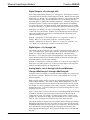
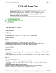
The CEN-IO contains eight VersiPorts. These eight input/output connections are
referenced to a common ground. Each connection can act as either a digital output
(<o1> through <o8>), a digital input (<i1> through <i8>), or an analog input
(<ain1> through <ain8>). Pullup resistors may be turned on or off for each
input/output connection (<pullup1-dis> through <pullup8-dis>). The following
subsections make use of the reference diagram, shown below.
CEN-IO Reference Diagram
Operations Guide - DOC. 5718
Ethernet Input/Output Module: CEN-IO • 1
Ethernet Input/Output Module
Crestron CEN-IO
Digital Outputs: <01> through <08>
When a logic high signal is placed on <o1> through <o8>, the output pin is shorted
to ground (switch S1-B in the reference diagram is closed). When a logic low signal
is placed on <o1> through <o8>, the output pin is driven to +5V (switch S1-B in the
reference diagram is open). This default behavior may be modified by placing a
logic high signal on <pullup1-dis> through <pullup8-dis>. When the pullup resistor
is disabled (switch S1-A in the reference diagram is open) and the corresponding
<o> signal is driven low, the output pin floats. When the pullup resistor is enabled
and the corresponding <o> signal is driven high, the output pin is shorted to ground.
Each signal <o1> through <o8> has a corresponding feedback <o1-f> through <o8f> that is driven by the CEN-IO. Feedback is provided from the CEN-IO for these
values since another non-Cresnet device on the network may talk directly to the
CEN-IO and modify its values.
Example: <pullup1-dis> is driven high. When <o1> is logic low, versiport 1 is
floating. When <o1> is driven high, versiport 1 is shorted to ground.
Example: <pullup1-dis> is driven low. When <o1> is logic low, verisport 1 is at
+5V. When <o1> is driven high, versiport 1 is shorted to ground.
Digital Inputs: <i1> through <i8>
The CEN-IO can detect when one of its versiports is shorted to ground or driven by
a 0 to 5 volt digital signal. When a pin is shorted to ground, the corresponding <i1>
through <i8> signal is driven to logic high in the program. The threshold for
detection is < +2.5V drives the signal in the program high. Note that for a contact
closure input, the pullup resistor should be enabled for that particular input (this is
the default behavior), else the input is floating.
Example: If versiport pin 5 is shorted to ground, <i5> is driven to a logic high level.
When pin 5 is not tied to ground, <i5> is driven to a logic high level (as long as the
pullup is left enabled, which is the default behavior).
Analog Inputs: <ain1> through <ain8> and Minimum
Change <MinChange1> through <MinChange8>
A resistive sensor (for example, a sensor that measures humidity) or a voltage source
may be tied to a vesiport. This sensor or source is represented by box "A" in the
reference diagram.
When a resistive load is tied to a versiport, the corresponding pullup resistor must be
enabled (default behavior). This creates a voltage divider and provides a varying
voltage level (based on the current resistance of the sensor) for the CEN-IO to read.
For example, if a resistive humidity sensor is tied to versiport 1, then <pullup1-dis>
should be driven low. The corresponding level is read as an analog value on <ain1>
and ranges from 0 to 65535.
When a voltage source is tied to a versiport, the corresponding pullup resistor should
be disabled. This allows the A/D convertor in the CEN-IO to directly read the
voltage source's value. For example, if a voltage source is tied to vesiport 1 then
<pullup1-dis> should be driven high. The corresponding level is read as an analog
value on <ain1> and ranges from 0 to 65535 (0 to +10V on the input pin).
The CEN-IO reports any change back to the program when an analog value changes.
Depending on the input source, this can result in excessive traffic over the network.
A minimum change value may be specified on a per-input basis. This tells the CENIO to wait until the corresponding analog input changes by the minimum value
before reporting into the program. This is useful if an input source is not clean and
has jitter.
2 • Ethernet Input/Output Module: CEN-IO
Operations Guide - DOC. 5718
Crestron CEN-IO
Ethernet Input/Output Module
Example: A voltage source is placed on versiport 1. <MinChange1> is set to 10 via
an Analog Initialize symbol. The <ain1> input does not exhibit any change until it
actually changes by 10. If the currently reported value is 500, for example, a new
value is not reported until it changes to 510 or 490.
Each signal <MinChange1> through <MinChange8> has a corresponding feedback
<MinChange1-f> through <MinChange8-f> that is driven by the CEN-IO. Feedback
is provided from the CEN-IO for these values since another non-Cresnet device on
the network may talk directly to the CEN-IO and modify its values.
Relay Inputs: <relay1> through <relay8> and Relay Outputs:
<relay1-f> through <relay8-f>
The CEN-IO symbol definiton can control the eight relays on the CEN-IO and
obtain true feedback as to the state of the relays in the CEN-IO.
The inputs to the symbol <relay1> through <relay8> allow the SIMPL program to
turn the relays on and off. A high signal on any of these lines turns on the respective
relay. A low signal turns the relay off. For example, if <relay1> has a high signal,
then the relay turns on.
Since the relay states may be changed by a source outside of the Cresnet system, the
symbol outputs <relay1-f> through <relay8-f> allow the Cresnet system to monitor
the state of the relays in the CEN-IO. If an external source changes the state of the
relay to closed, then the respective line is driven high. If an external source changes
the state of the relay to open, then the respective line is driven low. For example, if
an outside source closes relay 2, <relay2-f> goes high.
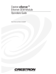
Physical Description
The CEN-IO is housed in a black enclosure with silk-screened labels on the front
and rear panels. On the front of the unit there are 21 LEDs for indicating the unit’s
current status. All connections, except for one Ethernet port, are made on t he back
of the unit. Refer to the physical views shown on the next page. There are four
rubber feet on the base of the unit for stability and to prevent slippage when the unit
is stored on a surface or stacked. Up to two units can be rack mounted with an
optional 19.00 inch (48.26 cm) rack mount kit (sold separately).
Operations Guide - DOC. 5718
Ethernet Input/Output Module: CEN-IO • 3
Ethernet Input/Output Module
Crestron CEN-IO
CEN-IO Physical Views
INPUT/OUTPUT
RELAY OUTPUT
CEN-IO Ports
Most ports are provided on the back of the CEN-IO. Each has a silk-screened label.
Refer to the illustration and descriptions below. There is only one port on the front
panel of the CEN-IO.
CEN-IO Ports (Rear Panel)
INPUT/OUTPUT
RELAY OUTPUT
12 VDC .5A
This DC power socket connector is used to supply external power via the supplied
500 mA power pack (1000 mA power pack for CENI-IO configuration).
PC
This 6-pin, 6-position RJ11 modular jack is used to load the IP address and run
diagnostics. Refer to the pinout table below.
PC Port (RJ11) Pinouts
PIN
DESCRIPTION
1
2
3
4
5
6
CTS
GND
RXD
TXD
RTS
No Connect
4 • Ethernet Input/Output Module: CEN-IO
Operations Guide - DOC. 5718
Crestron CEN-IO
Ethernet Input/Output Module
I/O (1 - 8, G)
This 9-pin connector (eight input/outputs and one common) is used to detect digital
and analog input/output levels. The contact closures to ground current is 2.5mA.
Port recognizes input/outputs compatible with TTL and CMOS digital signals and
can tolerate up to 24V DC. Threshold is 2.5V. Input/outputs can also measure analog
voltages from 0 to 10V DC.
RELAY OUTPUT (1 - 8)
This 12-pin connector provides eight normally open relays. Two relays share a
common ground. Each relay closure is rated at 24V DC/AC, 1A.
UNMARKED (Ethernet - on front panel)
This RJ45 connector provides Ethernet connection, thereby making the unit IP
addressable and compatible with 10BASE-T Ethernet systems. The Ethernet port is
the standard 10BASE-T pinout. Refer to the pinout table after this paragraph.
Ethernet Port (RJ45) Pinouts
PIN
DESCRIPTION
1
2
3
4
5
6
7
8
TD+
TDRD+
No Connect
No Connect
RDNo Connect
No Connect
CEN-IO Indicators
There are 21 LED indicators located on the front panel of the CEN-IO. Refer to the
illustration and descriptions below.
CEN-IO Indicators (Front Panel)
PWR (Power)
This LED illuminates when power is supplied to the CEN-IO.
RXD (Ethernet)
This LED illuminates during reception of Ethernet data by the unmarked Ethernet
port on the front panel.
TXD (Ethernet)
This LED illuminates during transmission of Ethernet data from the unmarked
Ethernet port on the front panel.
LNK (Ethernet)
This LED illuminates when there are attachments to the Ethernet port.
Operations Guide - DOC. 5718
Ethernet Input/Output Module: CEN-IO • 5
Ethernet Input/Output Module
Crestron CEN-IO
ERR (Ethernet)
This LED illuminates when an Ethernet protocol error is detected.
RELAY (1 - 8)
These LEDs illuminate when respective relay is closed.
I/O (1 - 8)
These LEDs illuminate when the input or output voltage threshold for respective
INPUT ports are exceeded.
Leading Specifications
The table below provides a summary of leading specifications for the CEN-IO.
Dimensions and weight are rounded to the nearest hundredth unit.
Leading Specifications of the CEN-IO
SPECIFICATION
Power Requirements
Relay Closure Rating
Input Threshold (per channel)
Input Analog Voltage Range (per channel)
Input Digital Voltage Range (per channel)
Switch Current (per channel)
SIMPL™ Windows®
CNX Operating System
Dimensions & Weight
*
DETAILS
12V DC
24V AC/DC, 1A
2.5V DC
0 to +10V DC
0 to +24V DC (compatible with
TTL & CMOS digital signals)
2.5mA (contact closure to ground)
Version 1.30.01 or later *
Version 5.04.11 or later
Height: 1.70 in (4.32 cm)
Width: 7.07 in (17.95 cm)
Depth: 6.32 in (16.06 cm)
TBS lbs. (TBS kg)
The latest software versions can be obtained from the Software Downloads page
(Simplwin Library) of the Crestron website (www.crestron.com). New users are required
to register in order to obtain access to the FTP site.
As of the date of manufacture, the unit has been tested and found to comply with
specifications for CE marking.
NOTE: This unit complies with part 15 of the FCC rules. Operation is subject to the
following two conditions: (1) these devices may not cause harmful interference, and
(2) these devices must accept any interference received, including interference that
may cause undesired operation.
Preparation for Use
Refer to the hookup diagram on the next page. Other than making the power
connection last, complete the connections in any order. The only connection not
shown in the diagram is the Ethernet/LAN connection made to the front panel of the
unit. Use a CAT 5 cable; not supplied.
6 • Ethernet Input/Output Module: CEN-IO
Operations Guide - DOC. 5718
Crestron CEN-IO
Ethernet Input/Output Module
Hookup Connections for CEN-IO
NOTE:
CABLES ARE NOT SUPPLIED.
ETHERNET CONNECTION NOT SHOWN.
TO
CONTROLLABLE DEVICES
FROM DEVICE OUTPUTS
PC
- CONTACT CLOSURES
- SOLID STATE CLOSURES
- LIGHTING SYSTEMS
INPUT/OUTPUT
RELAY OUTPUT
POWER PACK
(500 mA)
(1000 mA
for CENI-IO)
TO
CONTROLLABLE
DEVICES
Setup Menus
The CEN-IO setup menus can be accessed only after connecting the communications
port of the PC to the PC port on the CEN-IO. Communication cables are not
provided. Refer to “Preparation for Use” on page 6 for CEN-IO hookup details.
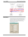
After connecting the CEN-IO and before applying power, open the communications
package that resides on the PC. Viewport from either SIMPL Windows or
VisionTools Pro is used in the illustrations that follow. Be sure to set the PC
communication parameters as shown below.
PC Communication Parameters
Operations Guide - DOC. 5718
Ethernet Input/Output Module: CEN-IO • 7
Ethernet Input/Output Module
Crestron CEN-IO
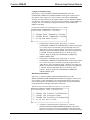
Apply power to the CEN-IO and notice that the MAIN MENU is displayed in the
Viewport window, shown below.
MAIN MENU in Viewport Window
The menu consists of 7 options. Selection is made by depressing the appropriate
number for each menu option.
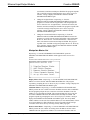
Network Functions
Depressing “1” from the MAIN MENU opens the NETWORK FUNCTIONS
MENU which appears on the screen as five options.
NETWORK FUNCTIONS MENU in Viewport Window
8 • Ethernet Input/Output Module: CEN-IO
Operations Guide - DOC. 5718
Crestron CEN-IO
Ethernet Input/Output Module
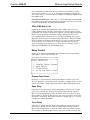
TCP/IP Configuration
Depressing “1” from the NETWORK FUNCTIONS MENU opens the TCP/IP
CONFIGURATION MENU which appears on the screen as six options.
TCP/IP CONFIGURATION MENU in Viewport Window
MAC Address - Depressing “1” from the TCP/IP CONFIGURATION MENU
displays the MAC address (## ## ## ## ## ##, where # represents an alphanumeric)
and prompts the user to ‘Press any key to continue’. Doing so displays the TCP/IP
CONFIGURATION MENU again. The MAC address can not be changed.
None of the changes to the
items marked with an asterisk
(*) takes effect until the unit
is restarted.
IP Address (*) - Depressing “2” from the TCP/IP CONFIGURATION MENU
allows the user to change the IP address for the connected CEN-IO. The program
displays the current IP address and prompts the user to enter an new IP address.
Enter the new address and depress ENTER. The program responds with the new IP
address and prompts the user to ‘Press any key to continue’. Doing so displays the
TCP/IP CONFIGURATION MENU again.
IP MASK (*) - Depressing “3” from the TCP/IP CONFIGURATION MENU
allows the user to change the IP mask for the connected CEN-IO. The program
displays the current IP mask and prompts the user to enter an new IP mask. Enter the
new mask and depress ENTER. The program responds with the new IP mask and
prompts the user to ‘Press any key to continue’. Doing so displays the TCP/IP
CONFIGURATION MENU again.
IP MTU (*) - Depressing “4” from the TCP/IP CONFIGURATION MENU allows
the user to change the IP MTU for the connected CEN-IO. The program displays the
current IP MTU and prompts the user to enter an new IP MTU. Enter the new IP
MTU and depress ENTER. The program responds with the new IP MTU and
prompts the user to ‘Press any key to continue’. Doing so displays the TCP/IP
CONFIGURATION MENU again.
Default router (*) - Depressing “5” from the TCP/IP CONFIGURATION MENU
allows the user to change the default router for the connected CEN-IO. The program
displays the current default router and prompts the user to enter an new default
router. Enter the new router and depress ENTER. The program responds with the
new default router and prompts the user to ‘Press any key to continue’. Doing so
displays the TCP/IP CONFIGURATION MENU again.
Operations Guide - DOC. 5718
Ethernet Input/Output Module: CEN-IO • 9
Ethernet Input/Output Module
Crestron CEN-IO
SNMP Configuration
Depressing “2” from the NETWORK FUNCTIONS MENU opens the SNMP
CONFIGURATION MENU which appears on the screen as four options.
SNMP CONFIGURATION MENU in Viewport Window
Configure NMS (Network Management Station) Trap catchers
Depressing “1” from the SNMP CONFIGURATION MENU opens the
CONFIGURE NMS TRAP CATCHERS MENU which appears on the screen as
four options. A NMS trap catcher is an NMS configured to receive the traps
originating from the CEN-IO.
CONFIGURE NMS TRAP CATCHERS MENU in Viewport Window
•
Display NMS Trap Catchers - Depressing “1” from the CONFIGURE
NMS TRAP CATCHERS MENU instructs the program to reveal its
three trap catchers. Once displayed, the program prompts the user to
‘Press any key to continue’. Doing so displays the CONFIGURE NMS
TRAP CATCHERS MENU again.
•
Add NMS Trap catcher - Depressing “2” from the CONFIGURE NMS
TRAP CATCHERS MENU permits the user to add a new trap catcher.
The program prompts the user to enter the trap catcher address. Enter
the address (#.#.#.#) and depress ENTER. The program responds by
repeating the new address and prompting the user to ‘Press any key to
continue’. Doing so displays the CONFIGURE NMS TRAP
CATCHERS MENU again. The newly added address overwrites the
first available address (0.0.0.0). If there are no addresses available, the
program responds with the message: ‘All three addresses are filled,
remove one before adding’.
•
Remove NMS Trap catcher - Depressing “3” from the CONFIGURE
NMS TRAP CATCHERS MENU permits the user to delete an existing
trap catcher. The program lists addresses for each trap catcher and
prompts the user to ‘Enter the entry number to remove’. Enter the entry
number (1, 2, or 3). The program responds by prompting the user to
‘Press any key to continue’. Doing so displays the CONFIGURE NMS
TRAP CATCHERS MENU again.
10 • Ethernet Input/Output Module: CEN-IO
Operations Guide - DOC. 5718
Crestron CEN-IO
Ethernet Input/Output Module
Configure Community Strings
Depressing “2” from the SNMP CONFIGURATION MENU opens the
CONFIGURE COMMUNITY STRINGS MENU which appears on the screen as
three options. These strings serve as passwords to read and write SNMP MIB
elements. The read community string (public default) is used to authenticate SNMP
‘Get Requests’. This parameter is also passed as the community string in SNMP trap
messages. The write community string (private default) is used to authenticate
SNMP ‘Set Requests’.
CONFIGURE COMMUNITY STRINGS MENU in Viewport Window
•
Change Read Community String - Depressing “1” from the
CONFIGURE COMMUNITY STRINGS MENU instructs the program
to reveal the current read community string and prompts the user to
‘Enter the new “Read Community String”’. Enter the new string (254
character maximum) and depress ENTER. The program responds with
a ‘SAVED’ message and prompts the user to ‘Press any key to
continue’. Doing so displays the CONFIGURE COMMUNITY
STRINGS MENU again.
•
Change Write Community String - Depressing “2” from the
CONFIGURE COMMUNITY STRINGS MENU instructs the program
to reveal the current write community string and prompts the user to
‘Enter the new “Write Community String”’. Enter the new string (254
character maximum) and depress ENTER. The program responds with
a ‘SAVED’ message and prompts the user to ‘Press any key to
continue’. Doing so displays the CONFIGURE COMMUNITY
STRINGS MENU again.
Miscellaneous Information
Depressing “3” from the SNMP CONFIGURATION MENU opens the
MISCELLANEOUS SNMP INFORMATION MENU which appears on the screen
as four options. Contact information is the textual identification for the managed
node. Assigned name is an administratively assigned name for this managed node.
Location information is the physical location of this node.
MISCELLANEOUS SNMP INFORMATION MENU in Viewport Window
•
Operations Guide - DOC. 5718
Change the Contact Information - Depressing “1” from the
MISCELLANEOUS SNMP INFORMATION MENU instructs the
program to reveal the current contact information value and prompts
the user to ‘Enter the new “Contact Information”’. Enter the new string
Ethernet Input/Output Module: CEN-IO • 11
Ethernet Input/Output Module
Crestron CEN-IO
(254 character maximum) and depress ENTER. The program responds
with a ‘SAVED’ message and prompts the user to ‘Press any key to
continue’. Doing so displays the MISCELLANEOUS SNMP
INFORMATION MENU again.
•
Change the Assigned Name - Depressing “2” from the
MISCELLANEOUS SNMP INFORMATION MENU instructs the
program to reveal the current assigned name value and prompts the
user to ‘Enter the new “Assigned Name”’. Enter the new name (254
character maximum) and depress ENTER. The program responds with
a ‘SAVED’ message and prompts the user to ‘Press any key to
continue’. Doing so displays the MISCELLANEOUS SNMP
INFORMATION MENU again.
•
Change the Location Information - Depressing “3” from the
MISCELLANEOUS SNMP INFORMATION MENU instructs the
program to reveal the current location information value and prompts
the user to ‘Enter the new “Location Information”’. Enter the new
name (254 character maximum) and depress ENTER. The program
responds with a ‘SAVED’ message and prompts the user to ‘Press any
key to continue’. Doing so displays the MISCELLANEOUS SNMP
INFORMATION MENU again.
Manipulate Master List
Depressing “3” from the NETWORK FUNCTIONS MENU opens the
MANIPULATE MASTER LIST MENU which appears on the screen as five
options.
MANIPULATE MASTER LIST MENU in Viewport Window
Display Master Lists - Depressing “1” from the MANIPULATE MASTER LIST
MENU reveals the STATIC and DYNAMIC MASTERS lists. The program
responds by prompting the user to ‘Press any key to continue’. Doing so displays the
MANIPULATE MASTER LIST MENU again.
Add Static Master - Depressing “2” from the MANIPULATE MASTER LIST
MENU permits the user to add a new master IP address and new master CRESNET
ID. The program prompts the user to enter the new master IP address. Enter the
address (#.#.#.#) and depress ENTER. The program prompts the user to enter the
new master CRESNET ID. Enter the address (####) and depress ENTER. The
program responds by prompting the user to ‘Press any key to continue’. Doing so
displays the MANIPULATE MASTER LIST MENU again. The newly added
address and ID overwrites the first available address (0.0.0.0) and ID (0000). If there
are no open addresses or IDs available, the program responds with the message:
‘The static master list is full. Try removing an entry and trying again’.
Remove Static Master - Depressing “3” from the MANIPULATE MASTER LIST
MENU permits the user to delete an existing master IP address and new master
CRESNET ID. The program lists addresses for each master IP address and new
12 • Ethernet Input/Output Module: CEN-IO
Operations Guide - DOC. 5718
Crestron CEN-IO
Ethernet Input/Output Module
master CRESNET ID and prompts the user to ‘Enter the entry number to remove’.
Enter the entry number (1, 2, 3, 4, or 5). The program responds by prompting the
user to ‘Press any key to continue’. Doing so displays the MANIPULATE MASTER
LIST MENU again.
Clear Dynamic Master List - Depressing “4” from the MANIPULATE MASTER
LIST MENU removes all current entries from the dynamic master list. Press any key
to return to the MANIPULATE MASTER LIST MENU.
PING (ICMP Echo) Test
Depressing “4” from the NETWORK FUNCTIONS MENU allows the user to
perform a PING from the CEN-IO to test the Ethernet connection and the TCP/IP
configuration. The program responds by revealing the source IP address and prompts
the user to enter the destination IP address. Doing so displays the packet size in
bytes and the program prompts the user to resize. Depress ENTER. The program
displays the number of packets to transmit and prompts the user change the number.
Depress ENTER. The program prompts the user if it is OK to run the test. Depress
‘Y’ to run the test or ‘N’ to abort. If ‘Y’ is depressed, the program runs the test,
reports its findings, and prompts the user to ‘Press any key to continue’. Doing so
displays the NETWORK FUNCTIONS MENU again.
Relay Control
Depressing “2” from the MAIN MENU opens the RELAY SELECTION MENU
which appears on the screen as four options.
RELAY SELECTION MENU in Viewport Window
Display Relay Status
Depressing “1” from the RELAY SELECTION MENU reveals the current relay
states (#1 through #8). The program further responds by prompting the user to ‘Press
space bar to continue’. Doing so displays the RELAY SELECTION MENU again.
Open Relay
Depressing “2” from the RELAY SELECTION MENU permits the user to open a
given relay (#1 through #8). The program responds with the message ‘SELECT
RELAY’ and prompts the user to ‘Press the number of the relay you wish to open’.
Enter a number (1 through 8). More than one relay can be opened in a session; enter
the numbers consecutively. When all the numbers are entered, depress ‘9’ to return
to the RELAY SELECTION MENU.
Close Relay
Depressing “3” from the RELAY SELECTION MENU permits the user to close a
given relay (#1 through #8). The program responds with the message ‘SELECT
RELAY’ and prompts the user to ‘Press the number of the relay you wish to close’.
Enter a number (1 through 8). More than one relay can be closed in a session, enter
Operations Guide - DOC. 5718
Ethernet Input/Output Module: CEN-IO • 13
Ethernet Input/Output Module
Crestron CEN-IO
the numbers consecutively. When all the numbers are entered, depress ‘9’ to return
to the RELAY SELECTION MENU.
VersiPort Control
Depressing “3” from the MAIN MENU opens the VERSIPORT SELECTION
MENU which appears on the screen as four options.
VERSIPORT SELECTION MENU in Viewport Window
Display All Inputs as Digital
Depressing “1” from the VERSIPORT SELECTION MENU reveals the current
digital state of the eight inputs (#1 through #8). The program further responds by
prompting the user to ‘Press space bar to continue’. Doing so displays the
VERSIPORT SELECTION MENU again.
Display All Inputs as Analog
Depressing “2” from the VERSIPORT SELECTION MENU reveals the current
analog value of the eight inputs (#1 through #8). The program further responds by
prompting the user to ‘Press space bar to continue’. Doing so displays the
VERSIPORT SELECTION MENU again.
Access Settings
Depressing “3” from the VERSIPORT SELECTION MENU permits the user to
review all the access settings for a given input (#1 through #8). The program
provides the given inputs digital state, analog value, analog threshold value, and
VersiPort connections. The program prompts the user to do one of the following.
•
Depress “1” to toggle the voltage state.
•
Depress “2” to toggle the grounding state.
•
Depress “3” to set the analog threshold.
•
Depress “4” and the space bar to access the setting of another
VersiPort. The program prompts the user with the ‘SELECT
VERSIPORT’ message. Either enter the number (1 through 8) or
depress ‘9’ to display the VERSIPORT SELECTION MENU.
Change Password
Passwords allow the user to access these menus via a TELNET session. Depressing
“4” from the MAIN MENU permits the user to alter the current password. The
program prompts the user to enter a new password. Enter the password and depress
ENTER. The program prompts the user to enter the new password again. Enter the
password and depress ENTER. If done correctly, the program responds that the
password was accepted. The program further responds by prompting the user to
‘Press space bar to continue’. Doing so displays the MAIN MENU again.
14 • Ethernet Input/Output Module: CEN-IO
Operations Guide - DOC. 5718
Crestron CEN-IO
Ethernet Input/Output Module
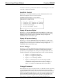
Restart Box
Depressing “6” from the MAIN MENU allows the user to restart the device. The
program responds with the ‘DO YOU REALLY WANT TO RESTART THE
DEVICE?’ message. Depress ’Y’ to restart or ‘N’ to abort the restart. Depress any
key to return to the MAIN MENU.
Upload Firmware
Depressing “7” from the MAIN MENU allows the user to upload the latest firmware
via the Serial connection. The program responds with the ‘READY FOR XMODEM
TRANSFER’ message and then proceeds to upload the firmware. When the upload
is complete, the program returns to the MAIN MENU.
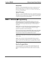
SIMPL™ Windows Programming
SIMPL (Symbol Intensive Master Programming Language) is an easy-to-use
programming language that is completely integrated and compatible with all
Crestron system hardware. The objects that are used in SIMPL are called symbols.
SIMPL Windows offers drag and drop functionality in a familiar Windows®
environment.
SIMPL Windows is Crestron Electronics' software for programming Crestron
control systems. It provides a well-designed graphical environment with a number
of workspaces (i.e., windows) in which a programmer can select, configure,
program, test, and monitor a Crestron control system.
The next two subsections describe a sample SIMPL Windows program that utilizes a
CEN-IO module. The first subsection details how the sample program works with a
textual description and block diagram. The second subsection provides a broad
description of how to actually create the SIMPL Windows program.
NOTE: The following description assumes that the reader has knowledge of
SIMPL Windows. If not, please refer to the extensive help information provided
with the software.
NOTE: There is no need to recreate the sample SIMPL Windows program. A
similar copy of this program is available from Crestron’s ControlCD (version 5.2
and later). Search for the CEN-IO.SMW project in the SIMPL Windows Example
Base.
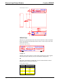
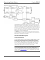
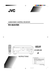
How the Program Works
A basic CEN-IO SIMPL program is shown below in block diagram form. This
example demonstrates a two zone lighting system (ZONE 1 and ZONE 2) that
utilizes a CT-3500 touchpanel as the user interface and a CEN-IO to control the
lights.
Operations Guide - DOC. 5718
Ethernet Input/Output Module: CEN-IO • 15
Ethernet Input/Output Module
Crestron CEN-IO
Block Diagram of System Incorporating a CEN-IO
The touchpanel has an ON and OFF button for each zone (join number 1 and 2 for
ZONE 1 and join numbers 3 and 4 for ZONE 2). Each zone has a light sensor that is
connected to an analog input of the CEN-IO. The lights can be turned off either via a
button press from the touchpanel or when the sensor detects a light level greater than
50% of its maximum value. The lights can be turned on via the button presses (join
numbers 1 and 3). The relays are used to control the lights. True feedback from the
lighting system is used from the digital inputs.
The MinChange is set to 10 to compensate for jitter on the values being reported
from the light sensors. The lights sensors in this example are resistive, therefore, the
pullup resistors in the CEN-IO are left enabled.
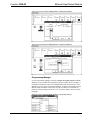
How to Create the Program
Configuration Manager
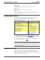
Use the Configuration Manager workspace (Project | Configure System) in SIMPL
Windows to select and configure all the devices that need to be included into the
system. For this example, from the Control Systems folder in the Device Library
select CNMSX-PRO. Drag and drop the CT-3500 (Touchpanels (Wired) folder in
the Device Library) and CEN-IO (Ethernet Control Modules folder) into System
View. For this example, the NET ID of the touchpanel must be set to 03 and the
CEN-IO IP Net Address must be set to 03, shown on the next page.
NOTE: SIMPL Windows v1.30.01 or later is required to program the control
system containing a CEN-IO. If using an earlier version of SIMPL Windows,
Crestron recommends a SIMPL Windows and operating system upgrade. The latest
version can be obtained from the Software Downloads page (Simplwin Library) of
Crestron’s website (www.crestron.com). New users are required to register in order
to obtain access to the FTP site.
16 • Ethernet Input/Output Module: CEN-IO
Operations Guide - DOC. 5718
Crestron CEN-IO
Ethernet Input/Output Module
System View of the CT-3500 in SIMPL Windows’ Configuration Manager
System View of the CEN-IO in SIMPL Windows’ Configuration Manager
Programming Manager
Use the Programming Manager workspace (Project | Program System) in SIMPL
Windows to select symbols and assign their respective signals. For this example, a
touchpanel and CEN-IO symbol were added automatically when the devices were
added to the system in the Configuration Manager workspace. Expand the Network
Modules folder and double click on the CT-3500 for a detail view (alternatively
CTRL+D or drag and drop into Detail View). Assign the signal as shown after this
paragraph.
Detail View of the CT-3500 in SIMPL Windows’ Programming Manager
Operations Guide - DOC. 5718
Ethernet Input/Output Module: CEN-IO • 17
Ethernet Input/Output Module
Crestron CEN-IO
Expand the Ethernet folder and double click on the CEN-IO for a detail view
(alternatively CTRL+D or drag and drop into Detail View). Assign the signal as
shown after this paragraph.
Detail View of the CEN-IO in SIMPL Windows’ Programming Manager
All logic symbols necessary for the SIMPL Windows program must be added from
the Symbol Library in the Programming Manager workspace. In this example, drag
and drop two Analog Initialize symbols from the Analog Operations folder, a
Multiple One Shot symbol from the Timers folder, and two Analog Compare and
two OR symbols from the Conditional folder into the Logic folder in Program View.
Expand the Logic folder and double click on symbol icons for a detail view
(alternatively CTRL+D or drag and drop into Detail View). Assign signals as shown
below and on the next page.
18 • Ethernet Input/Output Module: CEN-IO
Operations Guide - DOC. 5718
Crestron CEN-IO
Ethernet Input/Output Module
Detail View of the ANALOG INITIALIZE (S-1 and S2) in SIMPL Windows’ Programming
Manager
NOTE: For a more descriptive symbol name, as shown in the illustration above,
right mouse click on the symbol icon in the Logic folder in Program View and select
Edit Symbol Comment (alternatively, highlight the icon and depress Ctrl+R or
Tab). Enter a new descriptive name in the “Enter Symbol Comment” dialog box and
click OK.
Detail View of a MULTIPLE ONE SHOT (S-3) in SIMPL Windows’ Programming
Manager
Detail View of the ANALOG COMPARE (S-4.1 and S-5.1) in SIMPL Windows’
Programming Manager
Operations Guide - DOC. 5718
Ethernet Input/Output Module: CEN-IO • 19
Ethernet Input/Output Module
Crestron CEN-IO
Detail View of the OR (S-4.2 and S-5.2) in SIMPL Windows’ Programming Manager
Problem Solving
Troubleshooting
The table following this paragraph provides corrective action for possible trouble
situations. If further assistance is required, please contact a Crestron customer
service representative.
CEN-IO Troubleshooting
TROUBLE
Green PWR
LED does not
illuminate.
CEN-IO does
not
communicate
with PC.
CEN-IO does
not
communicate
with LAN.
POSSIBLE
CAUSE(S)
CORRECTIVE ACTION
CEN-IO is not
receiving power.
Confirm that power pack securely plugged
into outlet and that the connector is properly
attached to the CEN-IO.
Improper CEN-IO/PC Verify cable connections with PC: proper
cable connections.
connector is used, cable in intact, and
connections are secure.
Improper terminal
Use Viewport (F4) from either SIMPL
emulator used.
Windows or VT Pro.
Improper addresses Verify addresses via the Setup Menus
used.
described in this Operations Guide.
Improper CENVerify cable connections with LAN: proper
IO/LAN cable
connector is used, cable in intact, and
connections.
connections are secure.
Further Inquiries
If after reviewing this Operations Guide for the CEN-IO, you cannot locate specific
information or have questions, please take advantage of Crestron's award winning
customer service team by calling:
•
In the US and Canada, call Crestron’s corporate headquarters at
1-888-CRESTRON [1-888-273-7876] or 1-201-767-3400.
•
In Europe, call Crestron International at +32-15-50-99-50.
•
In Asia, call Crestron Asia at +852-2341-2016.
•
In Latin America, call Crestron Latin America at +5255-5093-2160.
•
In Australia, call Crestron Pacific at +613-9480-2999.
For local support from exclusive Crestron factory-trained personnel in New Zealand
call Amber Technologies at +649-410-8382.
20 • Ethernet Input/Output Module: CEN-IO
Operations Guide - DOC. 5718
Crestron CEN-IO
Ethernet Input/Output Module
Return and Warranty Policies
Merchandise Returns / Repair Service
1.
No merchandise may be returned for credit, exchange, or service without prior authorization
from CRESTRON. To obtain warranty service for CRESTRON products, contact the factory
and request an RMA (Return Merchandise Authorization) number. Enclose a note specifying
the nature of the problem, name and phone number of contact person, RMA number, and
return address.
2.
Products may be returned for credit, exchange, or service with a CRESTRON Return
Merchandise Authorization (RMA) number. Authorized returns must be shipped freight
prepaid to CRESTRON, Cresskill, N.J., or its authorized subsidiaries, with RMA number
clearly marked on the outside of all cartons. Shipments arriving freight collect or without an
RMA number shall be subject to refusal. CRESTRON reserves the right in its sole and
absolute discretion to charge a 15% restocking fee, plus shipping costs, on any products
returned with an RMA.
3.
Return freight charges following repair of items under warranty shall be paid by
CRESTRON, shipping by standard ground carrier. In the event repairs are found to be nonwarranty, return freight costs shall be paid by the purchaser.
CRESTRON Limited Warranty
CRESTRON ELECTRONICS, Inc. warrants its products to be free from manufacturing defects in
materials and workmanship under normal use for a period of three (3) years from the date of
purchase from CRESTRON, with the following exceptions: disk drives and any other moving or
rotating mechanical parts, pan/tilt heads and power supplies are covered for a period of one (1)
year; touchscreen display and overlay components are covered for 90 days; batteries and
incandescent lamps are not covered.
This warranty extends to products purchased directly from CRESTRON or an authorized
CRESTRON dealer. Purchasers should inquire of the dealer regarding the nature and extent of the
dealer's warranty, if any.
CRESTRON shall not be liable to honor the terms of this warranty if the product has been used in
any application other than that for which it was intended, or if it has been subjected to misuse,
accidental damage, modification, or improper installation procedures. Furthermore, this warranty
does not cover any product that has had the serial number altered, defaced, or removed.
This warranty shall be the sole and exclusive remedy to the original purchaser. In no event shall
CRESTRON be liable for incidental or consequential damages of any kind (property or economic
damages inclusive) arising from the sale or use of this equipment. CRESTRON is not liable for
any claim made by a third party or made by the purchaser for a third party.
CRESTRON shall, at its option, repair or replace any product found defective, without charge for
parts or labor. Repaired or replaced equipment and parts supplied under this warranty shall be
covered only by the unexpired portion of the warranty.
Except as expressly set forth in this warranty, CRESTRON makes no other warranties, expressed
or implied, nor authorizes any other party to offer any other party to offer any warranty, including
any implied warranties of merchantability or fitness for a particular purpose. Any implied
warranties that may be imposed by law are limited to the terms of this limited warranty. This
warranty statement supercedes all previous warranties.
Trademark Information
All brand names, product names, and trademarks are the sole property of their respective owners. Windows is a registered
trademark of Microsoft Corporation. Windows95/98/Me/XP and WindowsNT/2000 are trademarks of Microsoft
Corporation
Operations Guide - DOC. 5718
Ethernet Input/Output Module: CEN-IO • 21
Crestron CEN-IO
Ethernet Input/Output Module
Appendix
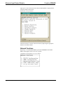
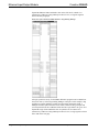
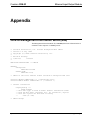
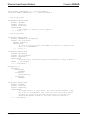
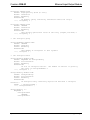
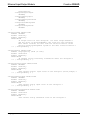
CEN-IO Management Information Block (MIB)
The Management Information Block file, cenio.mib, defines the information that is
available to other computers via SNMP protocol.
--------
Crestron Electronics, Inc. Private Enterprise MIB: CENIO
Version 1.0 July 1998
Copyright (C) 1998 Crestron Electronics, Inc.
Revision History:
7/98 Litt
created
CENIO-MIB DEFINITIONS ::= BEGIN
IMPORTS
enterprises
FROM RFC1155-SMI
OBJECT-TYPE
FROM RFC-1212;
-- CENIO is the first subtree within Crestron's enterprise MIB tree
crestron OBJECT IDENTIFIER ::= { enterprises 3212 }
crestron-CENIO OBJECT IDENTIFIER ::= { crestron 1 }
-- textual conventions
DisplayString ::=
OCTET STRING
-- This data type is used to model textual information taken
-- from the NVT ASCII character set. By convention, objects
-- with this syntax are declared as having
-SIZE (0..255)
-- CENIO Groups
Operations Guide - DOC. 5718
Appendix • 23
Ethernet Input/Output Module
Crestron CEN-IO
relay OBJECT IDENTIFIER ::= { crestron-CENIO 1 }
versiport OBJECT IDENTIFIER ::= { crestron-CENIO 2 }
-- the relay group
relayNumber OBJECT-TYPE
SYNTAX INTEGER
ACCESS read-only
STATUS mandatory
DESCRIPTION
"The number of relays in this system."
::= { relay 1 }
-- the relay table
relayTable OBJECT-TYPE
SYNTAX SEQUENCE OF RelayEntry
ACCESS not-accessible
STATUS mandatory
DESCRIPTION
"A list of relay entries. The number of entries is given by the
value of relayNumber."
::= { relay 2 }
relayEntry OBJECT-TYPE
SYNTAX RelayEntry
ACCESS not-accessible
STATUS mandatory
DESCRIPTION
"A relay entry containing objects the describe a relay instance."
INDEX
{ relayIndex }
::= { relayTable 1 }
RelayEntry ::=
SEQUENCE {
relayIndex
INTEGER,
relayDescr
DisplayString,
relayState
INTEGER
}
relayIndex OBJECT-TYPE
SYNTAX INTEGER
ACCESS read-only
STATUS mandatory
DESCRIPTION
"A unique value for each relay. Its value ranges between 1 and
the value of relayNumber. The value for each relay must remain
constant at least from one reinitialization of the entity's
network management system to the next reinitialization."
::= { relayEntry 1 }
24 • Appendix
Operations Guide - DOC. 5718
Crestron CEN-IO
Ethernet Input/Output Module
relayDescr OBJECT-TYPE
SYNTAX DisplayString (SIZE (0..255))
ACCESS read-write
STATUS mandatory
DESCRIPTION
"A textual string containing information about the relay."
::= { relayEntry 2 }
relayState OBJECT-TYPE
SYNTAX INTEGER
ACCESS read-write
STATUS mandatory
DESCRIPTION
"The current operational state of the relay (0=Open,1=Closed)."
::= { relayEntry 3 }
-- the versiport group
versiportNumber OBJECT-TYPE
SYNTAX INTEGER
ACCESS read-only
STATUS mandatory
DESCRIPTION
"The number of versiports in this system."
::= { versiport 1 }
-- the versiport table
versiportTable OBJECT-TYPE
SYNTAX SEQUENCE OF VersiportEntry
ACCESS not-accessible
STATUS mandatory
DESCRIPTION
"A list of versiport entries. The number of entries is given by
the value of versiportNumber."
::= { versiport 2 }
versiportEntry OBJECT-TYPE
SYNTAX VersiportEntry
ACCESS not-accessible
STATUS mandatory
DESCRIPTION
"A versiport entry containing objects the describe a versiport
instance."
INDEX
{ versiportIndex }
::= { versiportTable 1 }
VersiportEntry ::=
SEQUENCE {
versiportIndex
INTEGER,
versiportDescr
Operations Guide - DOC. 5718
Appendix • 25
Ethernet Input/Output Module
}
Crestron CEN-IO
DisplayString,
versiportDigitalInput
INTEGER,
versiportAnalogInput
INTEGER,
versiportAnalogThreshold
INTEGER,
versiportGroundingState
INTEGER,
versiportVoltageState
INTEGER
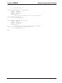
versiportIndex OBJECT-TYPE
SYNTAX INTEGER
ACCESS read-only
STATUS mandatory
DESCRIPTION
"A unique value for each versiport. Its value ranges between 1
and the value of versiportNumber. The value for each versiport
must remain constant at least from one reinitialization of the
entity's network management system to the next reinitialization."
::= { versiportEntry 1 }
versiportDescr OBJECT-TYPE
SYNTAX DisplayString (SIZE (0..255))
ACCESS read-write
STATUS mandatory
DESCRIPTION
"A textual string containing information about the versiport."
::= { versiportEntry 2 }
versiportDigitalInput OBJECT-TYPE
SYNTAX INTEGER
ACCESS read-only
STATUS mandatory
DESCRIPTION
"The current digital input state of the versiport (0=Low,1=High)."
::= { versiportEntry 3 }
versiportAnalogInput OBJECT-TYPE
SYNTAX INTEGER
ACCESS read-only
STATUS mandatory
DESCRIPTION
"The current analog input level of the versiport."
::= { versiportEntry 4 }
versiportAnalogThreshold OBJECT-TYPE
SYNTAX INTEGER
ACCESS read-write
STATUS mandatory
DESCRIPTION
"The current analog threshold value of the versiport."
26 • Appendix
Operations Guide - DOC. 5718
Crestron CEN-IO
Ethernet Input/Output Module
::= { versiportEntry 5 }
versiportGroundingState OBJECT-TYPE
SYNTAX INTEGER
ACCESS read-write
STATUS mandatory
DESCRIPTION
"The current grouding state of the versiport
(0=Grounded,1=Floating)."
::= { versiportEntry 6 }
versiportVoltageState OBJECT-TYPE
SYNTAX INTEGER
ACCESS read-write
STATUS mandatory
DESCRIPTION
"The current voltage state of the versiport
(0=No volatge supplied,1=Voltage supplied)."
::= { versiportEntry 7 }
END
_
Operations Guide - DOC. 5718
Appendix • 27
Crestron CEN-IO
Ethernet Input/Output Module
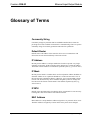
Glossary of Terms
Community String
Community strings are passwords that let an SNMP controlled device know the
priviledge level of the controller with which it is communicating. There are seperate
community strings for read only permission and read writer permission.
Default Router
Default router is the address of the router the device uses to communicate with
devices that are not connected directly to the local network.
IP Address
Internet protocol address is a unique number that is used to represent every single
computer in a network. All the computers on the internet have a unique IP address.
The format of the IP address is four numbers separated by dots (e.g., 198.123.456.7).
IP Mask
Internet protocol mask is a number that is used in conjunction with the IP address to
determine whether or not a particular IP address is on the local network. If it is on
the local network, communicate directly. Otherwise, use a router attached to the IP
network. The IP mask for any device should be assigned by whoever manages the
local network. The format of the IP mask is four numbers separated by dots (e.g.,
255.255.255.0).
IP MTU
IP MTU is the maximum packet size that the device can transmit. It is not necessary
to change this value from 1500 for an all ethernet network.
MAC Address
MAC address is a unique hardware address assigned to every network device in use.
The MAC address is assigned by Crestron at the factory and is never changed.
Operations Guide - DOC. 5718
Glossary of Terms • 29
Ethernet Input/Output Module
Crestron CEN-IO
Master List
Master list is a list of Crestron Internet Protocol (CIP) enabled devices that will be
informed of any changes in the state of the controlled device. The device accepts
commands from the addresses of these masters.
NMS Trap Catcher
NMS trap catcher is the address of a SNMP monitoring station that sends any alarm
messages that the monitored device wishes to send.
Router
Router is a communications device which routes data between networks.
SNMP
SNMP stands for Simple Network Management Protocol. It is part of TCP/IP that
deals with managing the devices in a network.
TCP/IP
TCP/IP stands for Transmission Control Protocol/Internet Protocol. It is quite simply
a standard set of protocols that govern the basic workings of the Internet that was
implemented in 1982.
The TCP part is all about ensuring that data is transmitted correctly between two
computers. If any errors occur these are detected and the data is retransmitted. The
data transmitted is split up into small portions called data packets. The IP part of
TCP/IP is how these data packets are moved from one point to another. Each
computer on the internet has a unique IP address and the data packets are moved
from the source to the destination through many different computers which is
controlled via TCP/IP. This protocol is used on the Internet and also by computers
that are part of a LAN.
30 • Glossary of Terms
Operations Guide - DOC. 5718
Crestron CEN-IO
Ethernet Input/Output Module
This page intentionally left blank.
Operations Guide - DOC. 5718
Glossary of Terms • 31