1
User’s Guide
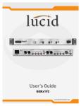
GENx192
Ultra Low Jitter
Studio Master Clock
Engineered by
User’s Guide
GENx192 Ultra Low Jitter
Studio Master Clock
Engineered by
Before You Begin
/16
What Ships in the Box
R A GENx192 hardware device.
Important Safety Instructions.
R A detachable power cord.
2. Keep these instructions.
R This User’s Guide.
3. Heed all warnings.
Getting Help
1. Read these instructions.
4. Follow all instructions.
If you have questions beyond the scope
of this User’s Guide or the help module,
contact our Customer Support Group in
the following ways:
5. Do not use this apparatus near water.
Do not place liquids or objects filled
with water on top of it, or where it
may be exposed to dripping, splashing or steam.
Tel
6. Clean only with dry cloth.
Web
(425) 778-7728
8:00 am to 4:30 pm
Monday through Friday,
Pacific Time
support.lucidaudio.com
7. Do not block any ventilation openings. Install only in accordance with
the manufacturer’s instructions.
8. Do not install near any heat sources
such as radiators, heat registers,
stoves, or other apparatus (including
amplifiers) that produce heat.
9. This apparatus shall be connected
to a mains socket outlet with a
protective earthing connection. Do
not defeat the safety purpose of the
polarized or grounding-type plug. A
polarized plug has two blades with
one wider than the other. A grounding
type plug has two blades and a third
grounding prong. The wide blade or
the third prong are provided for your
safety. If the provided plug does not
fit into your outlet, consult an electrician for replacement of the obsolete
outlet.
10.Protect the power cord from being
walked on or pinched particularly at
plugs, convenience receptacles, and
the point where they exit from the
apparatus.
11.Only use attachments/accessories
specified by the manufacturer.
This device complies with part 15 of the FCC
Rules. Operation is subject to the following
two conditions: (1) This device may not cause
harmful interference, and (2) this device must
accept any interference received, including
interference that may cause undesired
operation.
This Class A Digital apparatus meets all
requirements of the Canadian InterferenceCausing Equipment Regulations
Cet appariel numerique de la classe A
respecte toutes les Exigences du Reglement
sur le materiel brouilleur du Canada.
12.Use only with the cart,
stand, tripod, bracket,
or table specified by
the manufacturer, or
sold with the apparatus.
When a cart is used, use caution
when moving the cart/apparatus combination to avoid injury from tip-over.
13.Unplug this apparatus during lightning storms or when unused for long
periods of time.
14.Refer all servicing to qualified service
personnel. Servicing is required when
the apparatus has been damaged in
any way, such as power-supply cord
or plug cord is damaged, liquid has
been spilled or objects have fallen
into the apparatus, the apparatus has
been exposed to rain or moisture,
does not operate normally, or has
been dropped.
CAUTION
RISK OF ELECTRIC SHOCK
DO NOT OPEN
TO REDUCE THE RISK OF FIRE OR
SHOCK DO NOT EXPOSE
WARNING: ELECTRIC
THIS EQUIPMENT TO RAIN OR MOISTURE
DE CHOC ELECTRIQUE
AVIS: RISQUE
NE PAS OUVRIR
SEE OWNERS MANUAL. VOIR CAHIER D’INSTRUCTIONS.
No user serviceable parts inside. Refer servicing to qualified service personnel.
Il ne se trouve a l’interieur aucune piece pourvant entre reparée l’usager.
S’adresser a un reparateur compétent.
The lightning flash with arrowhead
symbol within an equilateral triangle is
intended to alert the user of the presence of uninsulated “dangerous voltage”
within the product’s enclosure that may
be of sufficient magnitude to constitute
a risk of electric shock to persons. The
exclamation point within an equilateral
triangle is intended to alert the user of
the presence of important operating and
maintenance (servicing) instructions in
the literature accompanying the product
(i.e. this User’s Guide).
CAUTION To prevent electric shock,
do not use the polarized plug supplied
with the unit with any extension cord,
receptacle, or other outlet unless the
prongs can be fully inserted.
Power Source. The Lucid
GENx192 hardware uses a switching
power supply that automatically adjusts
to the applied voltage. Ensure that
your AC mains voltage is somewhere
between 100-240 VAC, 50-60 Hz. Use
only the power cord and connector specified for the product and your operating
locale. A protective ground connection,
by way of the grounding conductor in the
power cord, is essential for safe operation. The appliance inlet and coupler
shall remain readily operable once the
apparatus has been installed.
User Serviceable Parts. There
are no user serviceable parts inside
the Lucid GENx192. In case of failure,
customers inside the U.S. should refer
all servicing to the Symetrix factory.
Customers outside the U.S. should refer
all servicing to an authorized Lucid distributor. Distributor contact information is
available online at www.lucidaudio.com.
User’s Guide
GENx192 Ultra Low Jitter
Studio Master Clock
Engineered by
Table of Contents
/16
Before You Begin
Introduction, Mechanical Data, Performance Data
Front Panel
Rear Panel
Basic Setup - Hardware Connections
Basic Setup - Front Panel
Clocks, Cables, and Termination
Sample Clocks
Common Clocking Problems
Clock Distribution - Star
Clock Distribution - Parallel
Clock Distribution - Serial
Cabling
Termination and Word Clock Drive Levels
Interfacing to Analog Systems
Declaration of Conformity
Warranty and Service
3
4,5
6
7
8
9
10-15
10
10,11
12
13
14
14
15
15
16
17
User’s Guide
GENx192 Ultra Low Jitter
Studio Master Clock
Engineered by
Introduction, Mechanical Data, Performance Data
/16
Introduction
Every piece of digital audio equipment has an internal sample clock that controls the timing of the A/D and D/A converters and
the transfer of audio through its digital audio interfaces. For optimal converter performance, the clock must be stable and free of
timing irregularities known as ‘jitter’ which can induce harmonic distortion and degrade stereo imaging. Additionally, to transfer
digital audio between various devices the clocks must be synchronized to a common ‘master’ timing reference, without which
clicks, pops and/or low-level noise will occur. Because most digital audio devices support only a single clock input or output,
many users resort to chaining clock signals from the output of one device to the input of another. Chaining clocks can lead to
clock phase differences and increased jitter as the signal proceeds down the chain.
The Lucid GENx192 Ultra Low Jitter Studio Master clock provides the ideal solution to most common clocking issues found in
today’s recording, post-production, and broadcast environments by providing a low-jitter clock reference that can be distributed
to a large number of devices simultaneously in multiple industry-standard formats and sample rates. The GENx192 features
eight (8) word clock, four (4) AES clock, and two (2) S/PDIF clock outputs capable of operating at sample rates of up to 192 kHz. The outputs are divided into two groups, each having independent control over sample rate. The GENx192 can also synchronize
to and re-distribute external word clock or AES signals ranging from 28 to 216 kHz. Finally, it can also function as a 1x4 AES-3
(audio) distribution amplifier.
Mechanical Data
Item
Specifications
Remarks
Rack Space
Required
1U (WDH: 48.02 cm x 22.15 cm x 4.37 cm /
18.91 in x 8.72 in x 1.72 in). (Depth is specified from front panel to back of connectors.)
Allow at least 1 inch additional clearance for rear panel connections. Additional depth may be required depending upon
your specific wiring and connections.
Electrical
100-240 VAC, 50-60 Hz, 25 Watts maximum.
Universal power input - no line voltage switching required.
Ventilation
Maximum recommended ambient operating
temperature is 30 C / 86 F.
Ventilation should not be impeded by covering the unit with
items such as newspapers, tablecloths, curtains, etc.
Shipping
Weight
3.70 kg / 8.15 lbs.
Performance Data
Inputs
Recommended Input Level
Word Clock: 2.0 to 5.0Vpp (nominal); 1.0 to 7.0Vpp (lock range)
AES: 2.0 to 7.0Vpp (nominal)
Input Impedance
Word Clock: 75Ω / 10kΩ switchable (Green “TERM” LED beneath the switch on
rear panel indicates proper Word Clock input termination)
AES: 110Ω
Outputs
Output Level
Word Clock: 5.2Vpp, unterminated; 4.0Vpp, 75Ω termination.
AES: > 3.6Vpp, 110Ω termination
S/PDIF: >0.3Vpp, 75Ω termination
Output Impedance
Word Clock: 24Ω
AES: 110Ω
S/PDIF: 75Ω
Maximum Cable Length
Word clock: 30.5 m / 100 ft (with 75Ω RG-59 or better coaxial cable)
AES: 30.5 m / 100 ft (with 110Ω shielded twisted pair cable)
S/PDIF: 10.0 m / 33 ft (with 75Ω RG-59 or better coaxial cable)
User’s Guide
GENx192 Ultra Low Jitter
Studio Master Clock
Engineered by
Introduction, Mechanical Data, Performance Data
/16
System
Internal Sample Rates
Internal Sample Rates: 44.1kHz and 48kHz base rates, multiplied by 2x and 4x to
88.2kHz, 96kHz, 176.4kHz, 192kHz
External Frequency Range
28kHz to 216kHz
Internal Clock Accuracy
± 25ppm
Clock Skew -- Any Output to Any
Output
< 1.00%, 28kHz to 216kHz, any output to any output.
TS-75 Word Clock Termination Sensing LEDs indicate condition of clock signals based on known and expected signal voltages and source and load termination conditions.
Clock Divisor Ranges
Output Sense:
Amber > 4.3Vpp
4.3Vpp ≥ Green ≥ 3.5Vpp
Red < 3.5Vpp
Input Sense:
Amber > 4.4Vpp
4.4Vpp ≥ Green ≥ 1.4Vpp
Red < 1.4Vpp
When an external clock falls within the frequency ranges prescribed below, the
clock is divided down in order to create the base rate for the unit.
÷1, 28kHz to 56kHz
÷2, 56kHz to 112kHz
÷4, 112kHz to 216kHz
User’s Guide
GENx192 Ultra Low Jitter
Studio Master Clock
Engineered by
/16
Front Panel
Front Panel
Item
Description
What It Does
RATE
8 Green LEDs
Displays the current sample clock rate as well as lock status. When SYNC SOURCE is
set to INTERNAL, both the LOCK LED and the corresponding base sample RATE LED
(44.1kHz or 48kHz) will be lit. When SYNC SOURCE is set to EXTERNAL (AES or WORD),
the LOCK LED be lit when a valid clock signal ranging from 28kHz to 216kHz is present; if
no signal is present or the clock is out of range, the LOCK LED will flash to indicate that the
GENx192 is not synchronized to the clock source.
When the external clock rate falls within ± 6.0% of a nominal sample rate, the corresponding
RATE LED will flash. When the external clock rate falls within ± 0.2% of a nominal sample
rate, the corresponding RATE LED will light solid. SYNC
SOURCE
4 position rotary
switch
Selects either an internal oscillator (44.1kHz or 48kHz) or an external clock source (AES or
word clock).
A OUTPUTS
3 position rotary
switch
Sets the sample rate for the A OUTPUTS. When an internal clock is used, the switch
multiplies the base rate (set by SYNC SOURCE) by either 1x, 2x, or 4x. However, when
an external clock is used, the switch can act as either a multiplier or divider, depending on
the rate of the external clock. For example, with an external 96kHz clock, the GENx192
generates 96kHz when the A OUTPUT switch is set to 96, 192kHz when set to 192 (x2), and
48kHz when set to 48 (÷2). See CLOCK DIVISOR RANGES for more information.
B OUTPUTS
3 position rotary
switch
Sets the sample rate for the B OUTPUTS. Functions identically to A OUTPUTS switch.
POWER
SWITCH
Rocker switch
Turns the unit off and on.
User’s Guide
GENx192 Ultra Low Jitter
Studio Master Clock
Engineered by
/16
Rear Panel
GENx192
WWW.LUCIDAUDIO.COM
B OUTPUTS
AES
TERMINATION:
GREEN = CORRECT
RED = OVER
AMBER = UNDER / N.C.
S/PDIF
A OUTPUTS
AES
WORD CLOCK
100-240 VAC
TERMINATION:
GREEN = CORRECT
RED = OVER
AMBER = UNDER / N.C.
T
E
R
M
MAXIMUM
MANUFACTURED BY SYMETRIX, INC. MTLK TERR, WA USA
THIS UNIT CONTAINS NO USER SERVICEABLE PARTS.
FABRIQUÉ AUX E.-U. PAR SYMETRIX, INC. MTLK TERR, WA USA
PAS DES ELEMENTS SERVIABLE PAR UTILISATEUR
T
E
R
M
T
E
R
M
INPUTS
T
E
R
M
T
E
R
M
T
E
R
M
T
E
R
M
TERMINATION:
GREEN = CORRECT
RED = OVER / NO SIG
AMBER = UNDER
WORD CLOCK
50-60 Hz
25 WATTS
AES
WORD CLOCK
T
E
R
M
T
E
R
M
Rear Panel
Item
Description
What It Does
POWER
INPUT
IEC 3 prong
jack
Accepts power from detachable IEC power cable (100-240 VAC, 50-60 Hz, 25 Watts max).
Connect only to a grounded power outlet.
S/PDIF OUT
2 x Female
RCA
Transmits either AES-3 (audio) or AES-11 (sync) data formatted for unbalanced S/PDIF
operating levels. Functionally identical to AES OUT.
AES OUT
4 x Male XLRs
Transmits either AES-3 (audio) or AES-11 (sync). When the SYNC SOURCE is set to AES
and the OUTPUT switch matches the rate of the incoming AES source, then the AES output format follows the input format and the GENx192 acts as a 1x2 or 1x4 AES distributor. WORD
CLOCK OUT
8 x Female
BNCs
Transmits phase-aligned CMOS-level word clock signals.
AES IN
Female XLR
Accepts single-wire AES-3 or AES-11 signals at sample rates between 28 and 216kHz.
WORD
CLOCK IN
Female BNC
Accepts TTL or CMOS-level word clock signals from 28 to 216kHz.
TERM
(Switch)
Push Button
Toggle Switch
Enables or defeats Word Clock input termination. (Green “TERM” LED beneath the switch
indicates proper Word Clock input termination.)
TERM
9 x Bi-color
LEDs
Displays the condition of the word clock input or output signal using voltage level sensing
to determine whether or not the signal is present, is operating at the correct levels, and is
terminated properly. An amber LED indicates an overvoltage or underterminated condition; for outputs, it can also indicate that no connection to a receiving device has been
made. A red LED indicates an undervoltage or overterminated condition; for the input, it
can also indicate that no connection to a source device has been made.
A green LED indicates optimal signal conditions with proper voltage and termination. However, because less is known about the word clock input signal than the output (due to
variances in standards and methods employed for generating word clock amongst the various equipment manufacturers) the tolerance range for the input is much less restrictive for
the input than the output to accommodate all possible valid conditions. A
User’s Guide
GENx192 Ultra Low Jitter
Studio Master Clock
Engineered by
Basic Setup - Hardware Connections
/16
POWER: Connect the IEC connector side of the supplied AC cord to the receptacle on the rear of
the GENx192. Connect the other side of the AC cable to an AC power source that is of the correct
voltage and frequency (100-240 VAC, 50-60 Hz). Use only the power cord and connector specified
for the product and your operating locale.
GENx192
AES
WWW.LUCIDAUDIO.COM
100-240 VAC
50-60 Hz
25 WATTS
MAXIMUM
MANUFACTURED BY SYMETRIX, INC. MTLK TERR, WA USA
THIS UNIT CONTAINS NO USER SERVICEABLE PARTS.
FABRIQUÉ AUX E.-U. PAR SYMETRIX, INC. MTLK TERR, WA USA
PAS DES ELEMENTS SERVIABLE PAR UTILISATEUR
GENx192
WWW.LUCIDAUDIO.COM
INPUTS (optional): If the GENx192 is being used to distribute an existing clock source, connect that clock
B OUTPUTS
A OUTPUTS
source to either the WORD CLOCK or AES input. Both inputs may be connected simultaneously but only
one input may be selected at a time using the SYNC SOURCE selection knob on the front panel.
TERMINATION:
GREEN = CORRECT
RED = OVER
AMBER = UNDER / N.C.
AES
S/PDIF
TERMINATION:
GREEN = CORRECT
RED = OVER
AMBER = UNDER / N.C.
AES
WORD CLOCK
T
E
R
M
T
E
R
M
T
E
R
M
INPUTS
AES
WORD CLOCK
T
E
R
M
T
E
R
M
T
E
R
M
T
E
R
M
TERMINATION:
GREEN = CORRECT
RED = OVER / NO SIG
AMBER = UNDER
WORD CLOCK
T
E
R
M
T
E
R
M
A USA
WORD CLOCK: Using a 75Ω coaxial cable (RG-59 or better) terminated
with male BNC
GENx192
connectors, connect one end to any of the eight GENx192 WORD CLOCK outputs, and the
other end into your destination device’s word clock input. Repeat as necessary to connect
multiple devices.
B OUTPUTS
AES
WWW.LUCIDAUDIO.COM
TERMINATION:
GREEN = CORRECT
RED = OVER
AMBER = UNDER / N.C.
S/PDIF
WORD CLOCK
100-240 VAC
50-60 Hz
25 WATTS
MAXIMUM
MANUFACTURED BY SYMETRIX, INC. MTLK TERR, WA USA
THIS UNIT CONTAINS NO USER SERVICEABLE PARTS.
FABRIQUÉ AUX E.-U. PAR SYMETRIX, INC. MTLK TERR, WA USA
PAS DES ELEMENTS SERVIABLE PAR UTILISATEUR
T
E
R
M
T
E
R
M
T
E
R
M
T
E
R
M
AES CLOCK: Using a 110Ω shielded, twisted pair cable terminated with one male and one female GENx192
XLR
connector, connect the female end to any of the four GENx192 AES outputs and the male end into your
destination device’s AES input. Repeat as necessary to connect multiple devices.
B OUTPUTS
AES
WWW.LUCIDAUDIO.COM
WO
100-240 VAC
50-60 Hz
25 WATTS
NOTE: Be sure that the designated AES input of your destination device can be configured as an AES
sync source for that device.
T
E
R
M
MAXIMUM
MANUFACTURED BY SYMETRIX, INC. MTLK TERR, WA USA
THIS UNIT CONTAINS NO USER SERVICEABLE PARTS.
FABRIQUÉ AUX E.-U. PAR SYMETRIX, INC. MTLK TERR, WA USA
PAS DES ELEMENTS SERVIABLE PAR UTILISATEUR
S/PDIF CLOCK: Using a 75Ω coaxial cable (RG-59 or better)
terminated with male RCA connectors,
connect one end
B OUTPUTS
GENx192
to either GENx192 S/PDIF output and the other end into your destination device’s S/PDIF input.
WWW.LUCIDAUDIO.COM
TERMINATION:
GREEN = CORRECT
RED = OVER
AMBER = UNDER / N.C.
AES
S/PDIF
WORD CLOCK
NOTE 1: Many consumer and “pro-sumer” devices do not offer Word or AES clock inputs. However, of those devices,
many do have S/PDIF digital audio inputs, such as the Digidesign 001 and 002 workstations. These devices typically
allow the S/PDIF input to be a sync source while allowing concurrent audio throughput from both the S/PDIF and other
ports (such as ADAT Optical). If your device fits this profile, the GENx192’s S/PDIF output will allow that device to
finally sync to the outside world!
100-240 VAC
50-60 Hz
25 WATTS
MAXIMUM
MANUFACTURED BY SYMETRIX, INC. MTLK TERR, WA USA
THIS UNIT CONTAINS NO USER SERVICEABLE PARTS.
FABRIQUÉ AUX E.-U. PAR SYMETRIX, INC. MTLK TERR, WA USA
PAS DES ELEMENTS SERVIABLE PAR UTILISATEUR
T
E
R
M
T
E
R
M
T
E
R
M
T
E
R
M
NOTE 2: There is no clock-only specification for S/PDIF digital audio, as there is within the AES specification. Therefore, the
S/PDIF output of the GENx192 is simply an unbalanced, transformer-coupled copy of the AES outputs. Most S/PDIF inputs will
accept the AES-formatted data, but compatilbility is not always guaranteed.
T
E
R
M
AES
User’s Guide
GENx192 Ultra Low Jitter
Studio Master Clock
Engineered by
Basic Setup - Front Panel
/16
Sync Source Selector
Lock and Rate Indicator LEDs
A Outputs Sample Rate Multiplier
B Outputs Sample Rate Multiplier
Power On/Off
Basic Setup - Illustration
The following illustration details the connections of a typical master clock setup in a visual format. In this setup, analog audio is
handled by an external A/D and D/A converter such as a Lucid 88192. After the converter, all audio is digital between a digital
multitrack recording device and a digital mixer. All devices sync to a dedicated word clock provided by the GENx192.
AES OUT
House Sync
(optional)
GENx192
WWW.LUCIDAUDIO.COM
B OUTPUTS
AES
TERMINATION:
GREEN = CORRECT
RED = OVER
AMBER = UNDER / N.C.
S/PDIF
A OUTPUTS
AES
WORD CLOCK
100-240 VAC
TERMINATION:
GREEN = CORRECT
RED = OVER
AMBER = UNDER / N.C.
AES
MAXIMUM
MANUFACTURED BY SYMETRIX, INC. MTLK TERR, WA USA
THIS UNIT CONTAINS NO USER SERVICEABLE PARTS.
FABRIQUÉ AUX E.-U. PAR SYMETRIX, INC. MTLK TERR, WA USA
PAS DES ELEMENTS SERVIABLE PAR UTILISATEUR
T
E
R
M
T
E
R
M
T
E
R
M
INPUTS
WORD CLOCK
T
E
R
M
T
E
R
M
T
E
R
M
T
E
R
M
TERMINATION:
GREEN = CORRECT
RED = OVER / NO SIG
AMBER = UNDER
WORD CLOCK
50-60 Hz
25 WATTS
T
E
R
M
WORD IN
A/D D/A Converter
WORD IN
Digital Recorder
T
E
R
M
WORD IN
Digital Mixer
WORD IN
Digital Effects
Device
The GENx192’s user interface consists of three simple multi-position selector knobs. Follow the guidelines below to setup the
GENx192 for use in the example shown above.
A. Power on.
B. Select the SYNC SOURCE and set the SYNC RATE:
1. Turn the SYNC SOURCE knob to select the internal base rate of either 44.1kHz or 48kHz based upon the desired final
output rate. For example, select 48 if you want 48kHz, 96kHz, or 192kHz. Select 44.1 if you want 44.1kHz, 88.2kHz or
176.4kHz. Both the green LOCK LED and the 44.1 or 48 green RATE LED rate will light.
2. Turn the A OUTPUTS knob to select the desired final output rate. This is a multiple (1x, 2x or 4x) of the base selected in
step one.
3. Repeat step 2 for B OUTPUTS if necessary.
If you’re connecting the GENx192 to an external sync source then proceed as follows:
A. Power on.
B. Select the SYNC SOURCE and set the SYNC RATE:
1. Turn the SYNC SOURCE knob to AES or WORD. If a valid AES or WORD input is present then the LOCK LED will light.
A flashing LOCK LED indicates that the selected SYNC SOURCE is either not present, out of range, or unusable. A RATE
LED will flash when the external clock rate falls within ± 6.0% of the indicated RATE. A RATE LED will light solid when the
external clock rate falls within ± 0.2% of the indicated RATE.
2. Turn the A OUTPUTS knob to select the desired final output rate.
3. Repeat step 2 for B OUTPUTS if necessary.
Note: Should the external sync source become disconnected or interrupted in some way, the GENx192 will switch to an internal
clock that is closest to the external clock rate. The GENx192 will continue to output sync at the closest internal rate until it is able
to lock to a valid external source once again.
User’s Guide
GENx192 Ultra Low Jitter
Studio Master Clock
Clocks, Cables, and Termination
Engineered by
/16
Sample Clocks
Within each piece of digital audio equipment are one or more clocks that control signal and timing relationships between
various internal components and external devices. The sample clock controls the A/D and D/A conversion rate and timing of
audio signal transfers through digital interfaces such as AES, TDIF, and ADAT optical. The rate at which this clock runs is
known as the Sample Rate. The most common ‘standard’ sample rates used in professional audio are 44.1kHz and 48kHz,
from which many other less common rates are derived.
To properly receive a digital signal transmitted from another device, the sample clocks of both sending and receiving devices
must precisely match each other. To use an analogy, imagine a machine placing parts onto a conveyor belt, while another
machine picks the parts off the other end of the belt and packages them. If both the first machine and the belt are running at a
constant rate, then the packaging machine must also take the parts off the line at precisely the same rate. Not only must the
packaging macine run at the identical rate, it must also pick the part off the belt at the exact moment the part passes it. If the
alignment is out of whack, then even though the packaging macine runs at the correct speed, it will miss every part.
As everyone knows, if you take two wristwatches, set them to the exact same time and start them at the same moment, a
week later they will not read the same time. The crystal oscillators used to generate the sample clock inside each digital audio
device are no different - no two crystal oscillators run at exactly the same rate. Therefore they must be synchronized externally
using a common ‘master’ clock signal that provides both frequency (rate) and position (alignment) information. This master
clock can be either any digital device in the system, or a dedicated clock generator such as the GENx192. Most professional
audio equipment, including DAT machines, digital consoles, A/D and D/A converters, and DAWs can slave their internal
sample clock to an external sample clock, unlike most consumer audio devices which cannot (such as CD players with digital
outputs).
Common Clocking Problems
Insuring proper system synchronization requires not only paying attention to the software and/or hardware configuration
of each device in the system, but also using the correct interconnection hardware (cabling, connectors, termination)
and employing the appropriate interconnection topology. Failing to do so may result in any one of a number of common
synchronization problems, some of which are not readily perceptible or easy to diagnose.
Jitter – Jitter refers to the amount of aperiodicity in a clock signal, and is generally measured in ‘nanoseconds’ (ns or
10-9 s). For example, a jitter-free 50kHz clock has exactly one clock cycle every 20µs (10-6 s). If the period of this clock
changes from 19.997µs to 20.001µs from one moment to the next, then the clock is said to have 4ns of jitter because
the period varies by 4ns. Jitter degrades the quality of the analog-to-digital and digital-to-analog conversion process by inducing harmonic
distortion into the signal, and therefore is hard to notice without comparing it to an ideal (extremely low jitter) signal
within the same listening environment. Jitter can also ‘smear’ the sharpness of a stereo image created with phasecoherent micing techniques (e.g. stereo-mic’d acoustic guitar). Because jitter can be considered as a signal that
modulates an ideal clock, it also has a frequency spectrum which affects the character of the distortion.
Jitter is the cumulative effect of numerous causes, ranging from poor grounding to the characteristics of the internal
circuitry of the equipment itself (noisy power supplies, signal crosstalk, circuit components, etc). While some of these
factors cannot be controlled, external factors such as cabling, termination, and clock distribution method can play a
significant contributing role.
Drift – Drift occurs when two or more audiovisual record/playback systems (DAW, digital tape, video, etc.) do not
share a common master clock. The problem is a direct consequence of the wristwatch illustration used above: when
two DAWs are both set to internal clocks at the same sample rate, and if they contain identical audio material and are
started at exactly the same time, then over time one DAW will begin to play back behind the other. Whereas it may
take hours or days for two wristwatches to drift from each other appreciably, in the digital world it typically takes only
seconds or minutes for noticeable drift to accumulate. Drift is invariably caused by a failure to set up the operating
parameters of the equipment correctly or to make the correct synchronization connections.
User’s Guide
GENx192 Ultra Low Jitter
Studio Master Clock
Clocks, Cables, and Termination
Engineered by
10/16
Pops, Clicks, Hash, and Distortion – Pops and clicks occur when the clocks between two digitally interconnected
devices running at different clock rates (for reasons stated above) move into and out of alignment with each other. As
misalignment occurs audio data is ‘dropped’, creating a discontinuity in the audio data. Similar to the beating of two
closely tuned strings, these pops and clicks occur at the same rate as the difference in speed between the two clocks.
If the clock rate difference is very slight, then the clocks will undergo a protracted period wherein data will be dropped,
causing a long burst of noise or ‘hash’ instead. In its most extreme forms (when jitter becomes > 5 to 10% of the clock
period), jitter can induce the same problems except that the period and rate of popping and distortion will be random.
In most cases such problems are immediately noticeable, and with a little listening and a bit of deductive reasoning the
source of the problem can be quickly found. Some problems are less apparent. Program material, listening levels and
monitor systems as well as certain types of digital interfaces can tend to mask the problem, which although present,
tends to be present at much lower levels in the material. When the clock rate difference is dramatic (for example
when a system running at 44.1kHz is interfaced to another running at 48kHz), then discrete pops and clicks cannot be
heard. Instead, the ‘resampled’ signal results in aliasing and severe harmonic distortion that sounds grainy and ‘digital’,
particularly in the high frequencies.
Skew – Skew is a misalignment of two clocks whose rates are otherwise synchronized. Skew is almost always caused
when devices are synchronized by chaining synchronization signals serially from one device to the other, instead of to
all devices from a single device. Skew can cause pops and clicks if the receiving device cannot receive data from the
transmitting device because of the particular phase relationship of the clocks. Skew can also cause timing differences in
the A/D and D/A conversion processes which can cause slight high-frequency phase cancellation and image smearing
if phase coherent material is distributed across the various sources. Skew should not be a problem in properly designed
equipment when the proper interconnection topology is used.
Malfunction – At worst, some devices cease to pass audio altogether when they cannot lock to an external clock. In
other cases their PLLs (Phase Locked Loops) may drift to invalid sample rates quite far from the target sample rate and
create all varieties of audible havoc both internally and with other interconnected audio devices.
Fortunately, employing a low jitter, low skew, centralized master clock / distributor like the Lucid GENx192
can solve most, if not all, of the above mentioned potential problems.
User’s Guide
GENx192 Ultra Low Jitter
Studio Master Clock
Engineered by
Clocks, Cables, and Termination
11/16
Clock Distribution - Three Common Approaches
There are several types of sample clock signals commonly used today: word clock, AES-3, AES-11, S/PDIF, and ADAT Optical. The GENx192 provides all of these except for ADAT Optical. AES-3, S/PDIF, and ADAT Optical are known as self-clocking interfaces because they carry both audio signals and clock data which receiving devices can slave their sample clocks to. TDIF, another popular digital interface format, is not a self-clocking interface because it must always be used along with an
external word clock signal. Word clock and AES-11 carry no audio information – they are synchronization signals only. There are three ways to distribute clock signals: in a serial chain, in a parallel chain, or in a star configuration. Often times a
setup may be a combination of two or three distribution methods.
Clock Distribution - Star
Master
Slave # 1
Slave # ..n
CLOCK OUT 1
CLOCK OUT 2
CLOCK IN
CLOCK OUT
CLOCK IN
CLOCK OUT
Star Clock Distribution
In a star configuration, a single ‘master’ generator distributes a clock signal to each device that requires it.
Without exception Star distribution should be used for every device that has a word clock or AES-11 (i.e. non self-clocking)
input. For this reason the GENx192 was designed with a large number of clock outputs to facilitate a proper star distribution
within all but the most demanding production environments. If at all possible, this is the way to go!
User’s Guide
GENx192 Ultra Low Jitter
Studio Master Clock
Engineered by
Clocks, Cables, and Termination
12/16
Clock Distribution - Parallel
In parallel clock distribution (word clock only), the clocks of multiple devices are connected to the same signal in parallel using
“T” connectors. In a proper parallel setup, the device at the end of the chain is terminated (low-impedance), and all devices in
between are unterminated (high-impedance) so as not to adversely load the signal down.
Master
Slave # 1
CLOCK IN
CLOCK OUT
CLOCK IN
CLOCK OUT
BNC ‘T’
Slave # ..n
CLOCK IN
BNC 75 Ohm
Terminator
CLOCK OUT
BNC ‘T’
Parallel Clock Distribution
Parallel distribution can be used effectively, but it also has drawbacks:
Termination Problems – Some manufacturers do not clearly mark the termination (input) impedance of their word clock
inputs. Thus it is quite easy to have two or more devices in the chain which are both terminated, causing a sharp drop
in clock signal level leading to synchronization failure in one or more devices. The GENx192 termination sensing LEDs
are designed to aid in diagnosing problems with multiple terminated inputs.
Reliability – Having multiple cables and multiple BNC-T connectors in the chain can lead to a higher incidence of mechanical failure.
Lack of Flexibility – Many devices cannot be unterminated, and therefore cannot be connected together in the same
parallel chain.
User’s Guide
GENx192 Ultra Low Jitter
Studio Master Clock
Engineered by
Clocks, Cables, and Termination
13/16
Clock Distribution - Serial
In serial clock distribution, clocks are chained from the output of one device to the input of another.
Master
Slave # 1
Slave # ..n
CLOCK IN
CLOCK OUT
CLOCK IN
CLOCK OUT
CLOCK IN
CLOCK OUT
Serial Clock Distribution
Serial distribution has several drawbacks and should be used only for devices that have self-clocking interfaces (e.g. certain
DAT machines and stand-alone CD burners, digital effects processors, etc.) These drawbacks include:
Signal Degradation – As the signal is passed from one device to another, the signal quality can become degraded the
farther down the chain it gets.
Clock Skew – Devices may add a small amount of delay to the output signal causing the clock edge to become progressively misaligned between each device in the chain.
Added Jitter – Each device has an inherent amount of jitter in its internal clocks. If the device regenerates the clock
rather than passing it through then the inherent jitter of the device will get added to the jitter contributed by all previous
devices. Any signal quality degradation will only exacerbate the jitter problem.
Cabling
Alwaysuse the correct cabling recommended for each type of clock signal. Improper cabling can lead to several of the problems described previously, such as clock signal degradation and jitter. The longer the cable run, the more critical it is to use the
correct cable.
Word Clock – Use 75Ω video coax (RG-59 or RG-6) with properly matched 75Ω BNC connectors. In a pinch you may
substitute 50Ω coax (RG-58) for very short runs only, but any use of 50Ω coaxial cable with a properly terminated word
clock input will cause signal reflections at the connector that can induce clock jitter.
AES -- Use 110Ω shielded, twisted pair digital audio cable. Because of the extremely high bandwidth of AES signals
(up to 25MHz), microphone cable should never be used for AES signals, even for very short runs.
S/PDIF – Use 75Ω video coax (RG-59 or or RG-6) with RCA male connectors designed for attachment to coaxial
cable. Unlike word clock, 50 Ω coax should not be used.
Belden, Canare, and Mogami all make excellent coaxial and digital audio cables that work well in these applications.
User’s Guide
GENx192 Ultra Low Jitter
Studio Master Clock
Clocks, Cables, and Termination
Engineered by
14/16
Termination and Word Clock Drive Levels
Unlike AES-3, AES-11, and S/PDIF, there are no published standards for word clock. While over the years certain common
word clock circuit design practices have emerged, compatibility between manufacturers is not guaranteed in all cases. Some
devices do not have sufficient output voltage to drive a properly terminated word clock input, while others require an unusually high input signal voltage to work properly. When two such devices are mated the result is that the receiving device may
intermittently lose lock or simply not lock at all. The GENx192 was designed to be compatible with all equipment on the market
today.
For ideal word clock transmission conditions to exist, the end of the cable must be ‘terminated’ with a load impedance that
exactly matches the cable impedance (75Ω.) “Ringing” occurs at the clock input when there is an impedance mismatch, adding jitter to the signal. Many devices are by default internally terminated with a 75Ω resistor; others are either user selectable
(through a switch or jumper), or are completely unterminated. Consult the operator’s manual for each piece of equipment to
determine the word clock input impedance. AES and S/PDIF do not have these termination issues – properly designed AES
and S/PDIF circuits should be correctly terminated already.
For point to point connections (such as in a star configuration), the word clock input should always be terminated. If the device
at the end of the cable cannot be internally terminated, then an external 75Ω BNC terminator and BNC-T connector must be
installed.
In a parallel configuration only the device at the end of the cable should be terminated, and all devices in the middle must be
unterminated (high-impedance). A ‘double-termination’ condition results when two devices on the same clock leg are terminated. This results in drastically lower clock voltage, and one or more of the units may fail to lock to the clock.
Interfacing to Analog Systems
Even today where the significant majority of recording and playback systems are digital, it is still necessary in certain production environments to synchronize the playback of analog systems such as VTR and multitrack tape machines to digital
systems that require clock synchronization. In the digital domain, word clock and AES-3/11 are used as timing references,
whereas in the analog domain video signals are commonly used.
To synchronize a VTR or analog multitrack to a digital system it is necessary to use a video blackburst signal as the master
timing reference. Blackburst is typically distributed from a single ‘house sync’ or stand-alone blackburst generator. Most digital systems do not have video sync inputs. It is therefore necessary to use a second clocking device that can receive a video
signal and output a ‘resolved’ digital sample clock that can be distributed through a device such as the GENx192 to all the digital equipment that requires it; a few generators can output both blackburst and resolved sample clock signals. These resolvers
work as synchronization ‘gearboxes’ by mathematically relating the video signal to the sample clock. For example, a resolver
can generate a 48kHz sample clock from a 30Hz video signal by outputting (48,000/30) = 1600 samples for every video frame.
Some DAWs and MDMs have video sync inputs as well as clock inputs. It is acceptable to use the video sync inputs on these
devices in lieu of clock ONLY when using analog inputs and outputs exclusively, AND when phase-coherent audio is NOT
distributed between the video synchronized devices(s) and other devices in the system. In all other cases, a valid clock system
must be used, particularly when using digital inputs and outputs. The reason for this is that in most video resolving circuits,
although the video frame rate can be adequately resolved to the sample clock rate, the phase alignment between the video
and clock signals is arbitrary. Therefore, if two devices are interconnected digitally but both resolved to black burst, the clock
alignment will be arbitrary and may cause misclocking.
User’s Guide
GENx192 Ultra Low Jitter
Studio Master Clock
Engineered by
Declaration of Conformity
15/16
Declaration of Conformity
We, Symetrix Inc.,
6408 216th St. SW, Mountlake Terrace, Washington, USA,
declare under our sole responsibility that the product:
GENx192 Ultra Low Jitter Studio Master Clock
to which this declaration relates,
is in conformity with the following standards:
EN 60065
Safety requirements for mains operated electronic and related
apparatus for household and similar general use.
EN 55103-1
Electromagnetic compatibility - Generic emission standard
Part 1: Residential, commercial, and light industry.
EN 55103-2
Electromagnetic compatibility - Generic immunity standard
Part 1: Residential, commercial, and light industry.
The technical construction file is maintained at:
Symetrix, Inc.
6408 216th St. SW
Mountlake Terrace, WA, 98043
USA
The authorized representative located within the European Community is:
World Marketing Associates
P.O. Box 100
St. Austell, Cornwall, PL26 6YU, U.K.
Date of issue: April 17, 2006
Place of issue: Mountlake Terrace, Washington, USA
Authorized signature:
Dane Butcher, President, Symetrix Incorporated.
User’s Guide
GENx192 Ultra Low Jitter
Studio Master Clock
Engineered by
Warranty and Service
The Symetrix Limited Warranty
Symetrix, Inc. expressly warrants that the product will be free
from defects in material and workmanship for eighteen (18)
months from the date the product is shipped from the factory.
Symetrix's obligations under this warranty will be limited to
repairing or replacing, at Symetrix's option, the part or parts
of the product which prove defective in material or workmanship within eighteen (18) months from the date the product
is shipped from the factory, provided that the Buyer gives
Symetrix prompt notice of any defect or failure and satisfactory
proof thereof. Products may be returned by Buyer only after
a Return Authorization number (RA) has been obtained from
Symetrix. Buyer will prepay all freight charges to return the
product to the Symetrix factory. Symetrix reserves the right to
inspect any products which may be the subject of any warranty
claim before repair or replacement is carried out. Symetrix
may, at its option, require proof of the original date of purchase
(dated copy of original retail dealer's invoice). Final determination of warranty coverage lies solely with Symetrix. Products
repaired under warranty will be returned freight prepaid via
United Parcel Service by Symetrix, to any location within the
Continental United States. Outside the Continental United
States, products will be returned freight collect.
The foregoing warranties are in lieu of all other warranties, whether oral, written, express, implied or statutory.
Symetrix, Inc. expressly disclaims any IMPLIED warranties, including fitness for a particular purpose or merchantability. Symetrix's warranty obligation and buyer's
remedies hereunder are SOLELY and exclusively as stated
herein.
This Symetrix Lucid product is designed and manufactured
for use in professional and studio audio systems and is not
intended for other usage. With respect to products purchased
by consumers for personal, family, or household use, Symetrix expressly disclaims all implied warranties, including
but not limited to warranties of merchantability and fitness for a particular purpose.
This limited warranty, with all terms, conditions and disclaimers set forth herein, shall extend to the original purchaser and
anyone who purchases the product within the specified warranty period.
Symetrix does not authorize any third party, including any
dealer or sales representative, to assume any liability or make
any additional warranties or representation regarding this
product information on behalf of Symetrix.
This limited warranty gives the buyer certain rights. You may
have additional rights provided by applicable law.
Note: Some Symetrix Lucid products contain embedded
software and may also be accompanied by control software
intended to be run on a personal computer. Said software is
specifically excluded from this warranty.
Limitation of Liability
The total liability of Symetrix on any claim, whether in contract,
tort (including negligence) or otherwise arising out of, connected with, or resulting from the manufacture, sale, delivery,
resale, repair, replacement or use of any product will not
16/16
exceed the price allocatable to the product or any part thereof
which gives rise to the claim. In no event will Symetrix be liable
for any incidental or consequential damages including but not
limited to damage for loss of revenue, cost of capital, claims
of customers for service interruptions or failure to supply,
and costs and expenses incurred in connection with labor,
overhead, transportation, installation or removal of products,
substitute facilities or supply houses.
Servicing the GENx192
If you have determined that your GENx192 requires repair
services and you live outside of the United States please
contact your local Lucid dealer or distributor for instructions on
how to obtain service. If you reside in the U.S. then proceed
as follows.
Return authorization
At the Symetrix factory, Symetrix will perform in-warranty or
out-of-warranty service on any product it has manufactured for
a period of three (3) years from date of discontinued manufacture.
Before sending anything to Symetrix, please contact our
Customer Service Department for a return authorization (RA)
number. The telephone number is (425) 778-7728. Additionally
support is available via the web site:
support.lucidaudio.com.
In-warranty repairs
To get your GENx192 repaired under the terms of the warranty:
1. Call us for an RA number (have the serial number, shipping
and contact information and description of the problem
ready).
2. Pack the unit in its original packaging materials.
3. Include your name, address, daytime telephone number,
and a brief statement of the problem.
4. Write the RA number on the outside of the box.
5. Ship the unit to Symetrix, freight prepaid. We do not accept
freight collect shipments.
Just do these five things, and repairs made in-warranty will
cost you only one way freight charges. We'll pay the return
freight.
If you don't have the factory packaging materials, we recommend using an oversize box. Wrap the unit in a plastic
bag, surround it with bubble-wrap, and place it in the box
surrounded by Styrofoam peanuts. Be sure there is enough
clearance in the box to protect the rack ears. We won't return
the unit in anything but Symetrix packaging for which we will
have to charge you. If the problem is due to operator misuse
or error, you will have to pay for both parts and labor. In any
event, if there are charges for the repair, you will pay for the
return freight. All charges will be COD unless you have made
other arrangements (prepaid, Visa or Mastercard).
Out-of-warranty repairs
If the warranty period has passed, you'll be billed for all necessary parts, labor, packaging materials, and freight charges.
Please remember, you must call for an RA number before
sending the unit to Symetrix.
Engineered by
6408 216th St. SW, Mountlake Terrace, WA, USA • Tel (425) 778-7728 • Fax (425) 778-7727 • Web www.lucidaudio.com
© 2006, Symetrix, Inc. All rights reserved. Printed in the United States of America. Symetrix Part Number 53G192-1A02. The information in this
User’s Guide is subject to change without notice. Symetrix, Inc. shall not be liable for technical or editorial errors or omissions contained herein; nor
is it liable for incidental or consequential damages resulting from the furnishing, performance, or use of this material. Mention of third-party products
is for informational purposes only and constitutes neither an endorsement nor a recommendation. Symetrix assumes no responsibility with regard to
the performance or use of these products. Under copyright laws, no part of this User’s Guide may be reproduced or transmitted in any form or by any
means, electronic or mechanical, without permission in writing from Symetrix, Inc. If, however, your only means of access is electronic, permission
to print one copy is hereby granted. Product names mentioned herein may be trademarks and/or registered trademarks of their respective owners.