1
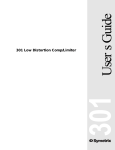
565E Users Guide 565E Dual Compressor/ Limiter/Expander Table of Contents 1 Chapter 2 Operator Safety Summary 2 Chapter 3 Fast Setup 3 Chapter 4 Tutorial 4 Chapter 5 Front Panel Overview 8 Chapter 6 Rear Panel Overview 10 Chapter 7 Connecting to Other Gear 11 Chapter 8 Applications 16 Chapter 9 Troubleshooting 19 Chapter 10 Specifications 20 Chapter 11 Warranty and Service 21 Chapter 12 Declaration of Conformity 23 565E Chapter 1 Introduction Rev C.0, 10 February, 1999 Symetrix part number 53565E0C00 Subject to change without notice. ©1999, Symetrix, Inc. All right reserved. Symetrix is a registered trademark of Symetrix, Inc. Mention of third-party products is for informational purposes only and constitutes neither an endorsement nor a recommendation. Symetrix assumes no responsibility with regard to the performance or use of these products. Under copyright laws, no part of this manual may be reproduced or transmitted in any form or by any means, electronic or mechanical, including photocopying, scanning, recording or by any information storage and retrieval system, without permission, in writing, from Symetrix, Inc. i 6408 216th St. SW Mountlake Terrace, WA 98043 USA Tel (425) 778-7728 Fax (425) 778-7727 Email: [email protected] Chapter 1 Introduction Congratulations on your purchase of the Symetrix 565E: a one-box answer to your dynamics processing needs. The 565E Dual Compressor/Limiter/Expander offers two channels of simultaneous, in-line controls for compression, limiting and downward expansion. In addition, the 565E employs a new circuitry design, Dynamics Squared, for dramatically reduced distortion during gain reduction. The separate limiter section guards against peaks that lead to overload problems, freeing the compressor section for settings specific to compression and not protection. (Trying to set a typical compressor for both compression and peak protection usually results in less-thanideal settings.) The 565E's limiter protects against sharp peak signals while the compressor smooths out the audio program for a silky, pleasing finish. Compression, limiting, and downward expansion clear up different but related audio problems. Whether you work with vocal tracks, stage monitors, radio signals, paging systems or playback systems, it's likely that your audio needs more than one of these solutions. The 565E's sidechain allows users to alter all three processing sections for special applications. Inserting an equalizer at the sidechain can make the action of the 565E's compressor/ limiter/expander frequency-dependent. Emphasize or de-emphasize a particular signal range to make the 565E respond more or less to certain frequencies. The compressor and expander sections of the 565E feature newly-developed circuitry, Dynamics Squared. This proprietary design addresses a key problem: most analog compressors use conventional voltage-controlled amplifier topography, which creates added distortion when compressing mid-band frequencies. Dynamics Squared resolves this problem by using circuitry that controls gain while reducing distortion. As a result, the 565E allows you to apply high levels of compression and expansion with much less distortion. Regardless of what your audio challenges may be, the 565E offers a powerful variety of solutions. In-line compression, limiting, and expansion produce clean, clear audio in any situation. Innovative circuitry permits users to choose optimal settings without paying the price of extra distortion. If background noise, tape hiss, or pickup hum is a problem, eliminate it with the downward expander. The 565E uses a true downward expander, not a so-called soft gate. The 565E's downward expander wont chop off the transients and decays like a gate would, yet it can work just as effectively for reducing those noises between sounds. Phone: (425) 778-7728 CH1 COMPRESSOR CH1 EXPANDER -18 -12 DUAL COMPRESSOR/ LIMITER/ EXPANDER -6 -2 -25 -15 -12 -10 0 -25 +10 -8 -6 -2 -12 BYPASS THRESHOLD (dBu) -25 FAST +5 -40 SLOW RELEASE 4 +20 THRESHOLD (dBu) SLOW RELEASE 6 1 -6 10 RATIO (X:1) -3 [email protected] CH2 EXPANDER -18 -12 STEREO LINK 0 +13 -12 Email: -20 -10 0dBu CLIP -3 +5 2.5 FAST -9 (425) 778-7727 CH1 OUTPUT CH1 LIMITER -4 -10 -12 Fax: Website:www.symetrixaudio.com While the downward expander quiets unwanted noise, the 565Es compressor section allows you to apply the right amount of compression without pumping or breathing. 565 E -10 BYPASS THRESHOLD (dBu) +10 -20 565E We recommend that you read this manual cover-to-cover. You will find the answers to most of your questions inside. Should you have any comments or questions, please do not hesitate to contact us at the numbers/ addresses below. Your calls are always welcome. IN BYPASS STEREO DUAL MONO CH2 COMPRESSOR -2 -25 -15 -12 -10 -8 -6 CH2 LIMITER -4 -2 -12 -10 0 -25 +10 +20 GAIN (dB) -6 -12 BYPASS THRESHOLD (dBu) -25 FAST +5 -40 SLOW RELEASE -9 4 2.5 FAST +20 THRESHOLD (dBu) SLOW RELEASE 6 1 -6 CH2 OUTPUT -20 -10 0dBu CLIP -3 +5 10 RATIO (X:1) -3 0 +13 -12 -10 +10 -20 BYPASS THRESHOLD (dBu) IN BYPASS +20 GAIN (dB) Front panel COMPRESSOR/ 565 E DUAL LIMITER/EXPANDER AC INPUT 15 WATTS MAXIMUM CHANNEL 2 OUTPUT BALANCED/ UNBALANCED SIDECHAIN KEY INPUT CHANNEL 2 INPUT BALANCED/ UNBALANCED FABRIQUÉ AUX E.-U. PAR SYMETRIX INC., LYNNWOOD, WA USA. RÉFÉREZ TOUTE RÉPARATION À UN TECHNICIEN QUALIFIÉ. BALANCED BALANCED CHANNEL 1 OUTPUT TYPICAL CONNECTIONS BALANCED INPUTS 1 2 3 MANUFACTURED IN LYNNWOOD, WASHINGTON USA GROUND=PIN 1 LOW(-)=PIN 3 HIGH(+)=PIN 2 1 2 3 1/4"BALANCED SIDECHAIN SLEEVE=GROUND RING=LOW(-) TIP=HIGH(+) GROUND SIDECHAIN OUT KEY INPUT BALANCED OUTPUTS BALANCED/ UNBALANCED SIDECHAIN KEY INPUT BALANCED CHANNEL 1 INPUT BALANCED/ UNBALANCED BALANCED Rear panel 1 Operator Safety Summary Equipment Markings CAUTION RISK OF ELECTRIC SHOCK DO NOT OPEN TO REDUCE THE RISK OF FIRE OR SHOCK DO NOT EXPOSE WARNING: ELECTRIC THIS EQUIPMENT TO RAIN OR MOISTURE DE CHOC ELECTRIQUE AVIS: RISQUE NE PAS OUVRIR SEE OWNERS MANUAL. VOIR CAHIER D’INSTRUCTIONS. No user serviceable parts inside. Refer servicing to qualified service personnel. Il ne se trouve a l’interieur aucune piece pourvant entre reparée l’usager. S’adresser a un reparateur compétent. The lightning flash with arrowhead symbol within an equilateral triangle is intended to alert the user of the presence of uninsulated "dangerous voltage" within the product's enclosure that may be of sufficient magnitude to constitute a risk of electric shock to persons. The exclamation point within an equilateral triangle is intended to alert the user of the presence of important operating and maintenance (servicing) instructions in the literature accompanying the product (i.e. this manual). Caution To prevent electric shock, do not use the polarized plug supplied with the unit with any extension cord, receptacle, or other outlet unless the blades can be fully inserted. Terms 565E Several notational conventions are used in this manual. Some paragraphs may use Note, Caution, or Warning as a heading. Certain typefaces and capitalization are used to identify certain words. These are: Note Caution Warning CAPITALS Boldface Identifies information that needs extra emphasis. A Note generally supplies extra information to help you to better use the 565E. Identifies information that, if not heeded, may cause damage to the 565E or other equipment in your system. Identifies information that, if ignored, may be hazardous to your health or that of others. Controls, switches or other markings on the 565E's chassis. Strong emphasis. Important Safety Instructions Please read and keep these instructions. Heed and follow all warnings and instructions. Install in accordance with the manufacturers instructions. Power Source This product is intended to operate from a power source that does not apply more than 250V rms between the power supply conductors or between either power supply conductor and ground. A protective ground 2 Chapter 2 connection, by way of the grounding conductor in the power cord, is essential for safe operation. Grounding The chassis of this product is grounded through the grounding conductor of the power cord. To avoid electric shock, plug the power cord into a properly wired receptacle before making any connections to the product. A protective ground connection, by way of the grounding conductor in the power cord, is essential for safe operation. Do not defeat the safety purpose of the grounding plug. The grounding plug has two blades and a third grounding prong. The third prong is provided for your safety. When the provided plug does not fit your outlet, consult an electrician for replacement of the obsolete outlet. Danger from Loss of Ground If the protective ground connection is lost, all accessible conductive parts, including knobs and controls that may appear to be insulated, can render an electric shock. Proper Power Cord Use only the power cord and connector specified for the product and your operating locale. Use only a cord that is in good condition. Protect the power cord from being walked on or pinched, particularly at plugs, convenience receptacles, and the point where they exit from the apparatus. Proper Fuse The user accessible fuse is a part of the IEC AC inlet connector. The fuseholder accepts 5 x 20mm diameter fuses. For 117VAC operation, the correct value is 0.2A, 250VAC, slow blowing. For 230VAC operation, the correct value is 0.1A, 250VAC, slow blowing. Operating Location Do not operate this equipment under any of the following conditions: explosive atmospheres, in wet locations, in inclement weather, improper or unknown AC mains voltage, or if improperly fused. Do not install near any heat source such as radiators, heat registers, stoves, or other apparatus (including amplifiers) that produce heat. Unplug this apparatus during lightning storms or when unused for long periods of time. Stay Out of the Box To avoid personal injury (or worse), do not remove the product covers or panels. Do not operate the product without the covers and panels properly installed. Only use accessories specified by the manufacturer. Clean only with a damp cloth. User-serviceable parts There are no user serviceable parts inside the 565E. In case of failure, refer all servicing to the factory. Servicing is required when the 565E has been damaged in any way, such as when a power supply cord or plug is damaged, liquid has been spilled or objects have fallen into the apparatus, the apparatus has been exposed to rain or moisture, does not operate normally, or has been dropped. Fast Setup Chapter 3 Fast First-Time Setup Follow these instructions to get your 565E up-and-running as quickly as possible. The intent of this section is fast setup. Refer to later chapters for explanation of the 565Es controls and functions. Connect the line-level signal source for Channel 1 to either the female XLR input jack (pin 2 hot) or the 1/4-in. TRS (tip-ring-sleeve, stereo, 3-conductor) input jack for Channel 1. Connect the line-level signal return to either the male XLR output jack or to the 1/4-in. TRS output jack for Channel 1. If you use the 1/4-in. jack, use a TRS plug for balanced circuits or use a TS plug for unbalanced circuits. Additional information on the signal connections may be found on pages 13-14 of this manual. If necessary, repeat for Channel 2. Ignore the SIDECHAIN (KEY INPUT) connections for now. Connect the AC input to an AC power source of the proper voltage and frequency, as marked on the rear of the unit. Caution: Failure to connect the 565E to the proper AC mains voltage may cause fire and/or internal damage. Warning: Lethal voltages are present inside the chassis. There are no user serviceable parts inside the chassis. Refer all service to qualified service personnel or to the factory. Make your initial switch and control settings as follows: SWITCH/CONTROL SETTING LIMITER OUTPUT THRESHOLD CONTROL RELEASE CONTROL THRESHOLD CONTROL RELEASE CONTROL RATIO CONTROL THRESHOLD CONTROL GAIN CONTROL BYPASS 12 OCLOCK -10 (12 OCLOCK) 12 OCLOCK 2:1 (APPROX. 10 OCLOCK) BYPASS 0 (12 OCLOCK) STEREO LINK STEREO/DUAL MONO SWITCH DUAL MONO (OUT POSITION) EXPANDER COMPRESSOR CHANNEL 2 REPEAT SETTINGS SHOWN FOR CHANNEL 1 With the 565Es controls and switches now set according to the preceding section, the 565E should pass signal. Fast setup is complete. Refining Your Settings Refine the EXPANDER THRESHOLD setting so that the expander reduces the gain of background noise when the desired input signal is not present, but does not reduce the gain when the desired signal is present and does not trigger excessively on short pauses in the program material. Adjust the COMPRESSOR THRESHOLD control so that two or three of the compressor gain reduction LEDs light when normal level program material is present. Set the LIMITER THRESHOLD control so that the -3 LED just lights on the highest peaks in the audio program material. Remember these settings are just guidelines; you can use whatever settings work best for you. 3 565E CHANNEL 1 Tutorial Chapter 4 Dynamics Processing Tutorial and 565E Functional Basics Audio signals possess several basic properties: amplitude or volume (measured in volts or dB), frequency or pitch (measured in Hertz), duration (measured in hours:minutes:seconds) and waveform (described graphically, like sine, square, triangle, or pulse). Complex signals like musical sounds are made up of simpler waveforms such as sine waves, mixed in the proper proportions. Signal processors allow you to manipulate various parameters of an audio signal. Equalizers change the amount of amplification given to different frequencies (a perfect amplifier increases the gain of all frequencies by the same amount). Dynamics processors change the dynamic range of audio signals. The dynamic range of an audio signal is the difference between its loudest and softest moments. For audio equipment, this is the difference between the noise floor (residual noise output, with no input signal) and peak clipping (the point at which the output clips or distorts). A hypothetical black-box having a noise floor of -90 dBu and a maximum peak output level of +24 dBu would have a dynamic range of 114 dB (+24 minus -90). Audio storage devices like tape machines have a much narrower dynamic range; a typical professional analog two-track tape machine may have a dynamic range of 65 to 70 dB. If youve used an analog tape recorder before, then you are already familiar with the problem of setting recording level. Record too hot and you get distortion; record too cold and get noise in return. Many musical instruments have dynamic ranges that exceed that of most tape recorders. So, how do we squeeze a 80 or 90 dB signal into a 60 or 70 dB window? The answer lies in a common audio signal processor: the compressor. Compressors and Limiters 565E A compressor or limiter monitors the level (or amplitude) of a signal and reduces the amplitude according to a rule whenever the signal level exceeds a predetermined level. The predetermined level is known as the threshold level and is usually set by a front-panel control. The amount by which the compressor lowers the level is the compression ratio, and this parameter is usually set via a front-panel control as well. Compression ratio refers to the ratio of a change at the input versus the change at the output of the device. Thus, if we apply an above-threshold signal that changes 10 dB to the input of a hypothetical compressor, and measure a 2 dB change in the output signal, that compressor would have a compression ratio of 10:2, or 5:1 (reduce the fraction). Different compression ratios have different uses. Use lower ratios (6:1 or less) for level control, intermediate ratios (8:1 to 12:1) for leveling (making the signal level more or less constant), and higher ratios for limiting (putting an absolute ceiling on the signal level). Limiters are nothing more than compressors, but are possessed of much higher compression ratios (20:1 or higher). Limiters are typically used to stop occasional peaks which would otherwise cause overload or distortion. Typically a limiter is set (via its threshold control) so that it stays out of the way until a peak comes along. Expanders and Gates While a compressor or limiter reduces the dynamic range of a signal by reducing its level once it has exceeded a threshold level, an expander does the opposite (well, almost). The easiest way to visualize an expander is to think of it making loud signals louder. This is fine, except that in the real world, the device following the expander (such as a processor or an amplifier) would go into terminal overload. The solution is to make soft signals softer, a.k.a. downward expansion. This is what the 565Es downward expander does. When the signal level falls below the level set by the threshold control, the expander reduces its gain by the amount dictated by its expansion ratio. Thus, for a below-threshold signal, a 10 dB output change results from a 5 dB change in the input signal, if the expansion ratio is 1:2. 4 A gate is similar to an expander except that its ratio is much higher; thus the action is more like a switch once the signal falls below threshold. Some expander applications for the 565E may be quite similar to a gate, like tending a lone announce microphone, but downward expanders generally are not well-suited to typical gate applications such as removing leakage from drum microphones, where very tight control is desired. Ratio The compression ratio of the 565E determines how much the output changes for a change in the input. A linear amplifier (like a simple preamp) has a ratio of 1:1 because a change of 1 dB at its input results in a 1 dB change at its output. A compressor alters the input/output relationship by its compression ratio. Thus a 20:1 ratio means that a 20 dB above-threshold change at the input results in a 1 dB change at the output. In other words, a very audible change at the input (20 dB) turns into a barely discernible change at the output (1 dB). Compressors are not the only devices to have an input/output ratio. Any device that is capable of changing the input/output relationship can be said to have a ratio. Thus expanders, gates, compressors and limiters all fit this category. An expander magnifies output changes for a given input change. Thus, once the input signal falls below threshold, the expander changes the output by the amount of the ratio. The 565Es downward expander has an expansion ratio of 1:1.5, which means that a below-threshold input signal that gets 10 dB quieter turns into an output signal that gets 15 dB quieter. A gate can be looked at as an expander with an infinite expansion ratio. Thus the slightest peak in the input signal from below-threshold to above-threshold switches the gate from closed to open. The GAIN control compensates for signal level lost to compression. As an example, set the THRESHOLD control counter-clockwise and set the RATIO control of the 565E for a 4:1 ratio. Now adjust the THRESHOLD control for 10 dB of gain reduction as viewed on the compressors gain reduction display. The output level should be significantly lower than it was when the Threshold control was counter-clockwise (i.e. when no compression was being applied). You supply the additional gain (make-up gain) by adjusting the GAIN control until the input and output signal levels match. Release Time Most dynamics processing equipment has a control marked RELEASE on the front panel. This control refers to release time, and it affects the length of time required for the gain to recover to the no-signal state (when no signal is applied to the input). The release time control allows tailoring the expanders or compressors recovery time to the program material. For compressors, the no-signal state is unity gain (passing the signal straight through the compressor, with no change in gain). Compressors pass any signal whose level is below threshold at unity gain. The release time control determines how long it will take for the compressor to return to unity gain, once the input signal has fallen below the compression threshold. Generally, peak limiting is associated with short release times and compression or leveling associated with longer release times. For expanders, the no-signal state is determined by the amount of gain reduction applied when no signal is present at the expanders input. The amount of gain reduction is set by the threshold control and by the ratio of the expander, and this applies to any signal whose level is belowthreshold. In this case, the release time control governs how long it takes for the expander to reduce the gain when the signal disappears. Typically, smooth expansion of speech or music is associated with longer release times, and gating-type functions, such as feedback suppression, are associated with short release times. 5 565E Gain versus Output Level Setting the Threshold Control The THRESHOLD control sets the audio signal level where the compressor/expander/limiter begins working. In the case of the compressor or limiter, the processor begins working once the signal has exceeded the threshold level. For the expander, it begins working once the signal has fallen below the threshold level. For any of the three processors, the THRESHOLD control setting also determines the degree or amount of gain reduction. Thus, for the compressor, rotating the control counter-clockwise (towards -40) results in increasing amounts of compression. For the expander, counter-clockwise rotation raises the level that the signal must exceed to pass through the expander untouched. This has the effect of shutting off the signal once you reach and then pass the threshold level. For most compressor applications, moderate amounts of gain reduction are all that is required, 3-9 dB at the most. If you are using the compressor to minimize level changes of a wide range of program material (automatic level control), then higher amounts of gain reduction are needed. In typical compressor applications, program material with a very wide dynamic range calls for higher amounts of gain reduction than program material with less dynamic range. Note With higher amounts of gain reduction, slower release times are recommended. Interpreting the Displays The 565E has one display per processing section. The three displays associated with the expander, compressor and limiter indicate a parameter called gain reduction. Simply stated, the gain reduction indication shows how far the gain or amplification was reduced from unity. Another way of looking at this is: if the gain reduction display says 10 dB of gain reduction, switching the unit to bypass will result in a 10 dB increase in the output level. The output display indicates output level in dBu. For most applications, just make certain that you never see the CLIP LED illuminate. 565E Using the Sidechain The sidechain is a patch point in the control circuit of a dynamic range processor. It provides access to the part of the circuitry that tells the VCA (voltage controlled amplifier) what to do. The 565Es sidechain is routed through a TRS jack labeled KEY INPUT. This jack is located on the rear panel, and it provides both a send and return via the same jack. The sidechain connection affects all three processors in the 565E. The 565Es sidechain connections are derived from the balanced input stage, and they allow access to the control circuits input signal. The control signal is derived from, but kept totally separate from, the audio signal path. This means that the control signal can be processed outside the 565E without actually processing the signal thats going through the VCA (the audio signal itself). This presents some very interesting possibilities for changing or improving the operation of the dynamic range processor. The most common use of the sidechain is to make the action of the 565Es compressor/limiter/ expander frequency dependent, that is, to make it respond more (or less) to certain frequencies, by inserting an equalizer in the sidechain path. Because the audio signal and the control signal remain completely separate (even while the control circuit tells the VCA whether to turn the gain up or down), you can equalize just the sidechain without changing the EQ in the main audio path. This allows you to emphasize a frequency portion of the audio program so that this portion dictates the behavior of the processing (for example, you can boost the appropriate high frequencies to make the compressor behave like a de-esser), or to de-emphasize a frequency portion that is controlling the audio more than you would wish (for example, with beat-heavy dance music, cutting the low end can prevent the compressor from pumping and breathing with every kick drum beat). 6 Keep in mind that the threshold level becomes a function of the amount of overall gain through the equalizer, including the boost. This technique can be used with any frequency that can be controlled by the equalizer. One occasion for using an EQ in the sidechain is when low frequency signals transmitted through a desk or podium are triggering the 565Es expander unnecessarily. You can solve this problem by using an equalizer in the sidechain to remove the low frequencies from the control signal or to boost the voice-range frequencies in the control signal. When the offending frequencies are removed or minimized, the relative level of the desired frequencies increases. The expander can now tell the difference between the wanted and unwanted signals. Use this technique in any situation where levels are nearly the same, but the fundamental frequencies involved are different. Note The ability of the expander to discriminate between wanted and unwanted signals is partially determined by mic technique. Be particularly careful of high frequency sounds entering the side or rear pattern of a cardioid mic. Most cardioid mics exhibit a sharply rising off-axis response characteristic at higher frequencies. Check the off-axis curve (the lower one) in the manufacturers literature. If theres only a 3dB to 6dB difference between the on-axis (frontal) response and the off-axis (side or rear) response in the 5kHz to 10kHz reason, high frequency sounds will be picked up by the side or back of your mic. Use the mics directional pattern to keep other sources as far off-axis as possible - do everything you can do to extract all the source-to-source discrimination possible through good mic technique. The sounds picked up by individual mics must be primarily the sound of the desired signal, or the expander wont be able to tell the difference. You can save time, and make life easier, by listening to the output of the equalizer (instead of the 565Es output) that youre using in the sidechain. Doing this allows you to hear the signal that will control the 565E, and perhaps to find the range that you wish to emphasize or de-emphasize more easily. 565E Hint 7 Front Panel Overview Chapter 5 Expander Section CH1 EXPANDER -18 -12 -6 -2 -12 0 -25 +10 BYPASS FAST THRESHOLD (dBu) SLOW T HRESHOLD control - The THRESHOLD control varies the downward expander threshold from +10dBu to BYPASS. The downward expander will engage when the audio signal present at the input of the expander drops below this threshold, or when there is no signal present at the expanders input. The downward expander gently lowers below-threshold signals at a ratio of 1:1.5 (a 1dB belowthreshold drop in signal at the expanders input results in a 1.5dB drop in signal at the expanders output). RELEASE R ELEASE control - The RELEASE control allows the user to vary the downward expander release time from 250 milliseconds to 5 seconds. The release time is the amount of time that it takes for the downward expander to push the output signal down to the level determined by the 1:1.5 ratio, in response to an instantaneous below-threshold drop in the input signal level. Shorter release time settings cause the expander to act more quickly, and longer release time settings cause the expander to act more slowly and smoothly. LED display - The LED display indicates the amount by which the expander has reduced the level of the input signal. The Compressor Controls CH1 COMPRESSOR -25 -15 -12 -10 -8 -6 -4 -2 565E -10 -25 4 +5 -40 +20 THRESHOLD (dBu) 2.5 FAST SLOW RELEASE 6 1 10 RATIO (X:1) THRESHOLD control - The THRESHOLD control varies the compressor threshold from -40 dBu to +20 dBu. The compressor threshold is the level that the input signal must reach before the compressor becomes active. When the input signal exceeds this threshold, the compressor will reduce the output gain by the amount determined by the compressor RATIO control setting. R ELEASE control - The RELEASE control allows tailoring of the compressors recovery time to the program material. Generally, peak limiting is associated with short release times and compression, or leveling, is associated with longer release times. The 565Es release circuitry has a unique dual-release time feature designed to make life easier. The dual-release feature makes the release time partially program-dependent, giving you the best of both worlds: fast release for short-duration peaks and a longer release time for longerduration peaks. The RELEASE control adjusts the speed of the longer of the two. The compressor release time can be varied from 180 milliseconds to 2.5 seconds. R ATIO control - The RATIO control determines the amount of compression that occurs for a given above-threshold change in the input level. The ratio that is being controlled is the ratio between an above-threshold change in the input level and the resulting change in the output level. If the RATIO control is set to 10:1, then a 10 dB above-threshold change in the input level would result in only a 1 dB change in the output level. Higher ratios are used where tighter control is desired, such as when you want to control peaks in the audio signal, and lower ratios are used for gentle smoothing of levels. LED display - The LED display indicates the amount by which the output level has been reduced by the compressor. 8 The Limiter Controls THRESHOLD control - The THRESHOLD control sets the level to which the input signal must rise before limiting occurs. Once the audio input signal rises above this threshold, the output gain will be reduced by a ratio of 20:1 (i.e. an above-threshold signal increase of 20 dB at the input would result in only a 1 dB signal increase at the output). CH1 LIMITER -12 -9 -6 -3 +5 -3 LED display - The LED display indicates the amount by which the output level has been reduced by the limiter. +13 -12 BYPASS THRESHOLD (dBu) The Output Controls -20 -10 0dBu CLIP 0 -10 IN BYPASS +10 -20 GAIN control - The GAIN control sets the final output signal level. This control can be used to increase the output level, up to +20 dB, or to decrease the output level, by as much as -20 dB. This control can be used, if needed, to restore signal level lost by compression or limiting, to make up for the 6dB drop in output level that occurs when you connect an unbalanced cable to the 565Es output, or to reduce the 565Es output level to prevent overdriving the input stage of the next device in the signal chain. Note +20 GAIN (dB) The unity gain position (0) of the GAIN control is referenced to the balanced output connector. If you are using the unbalanced output, unity gain occurs when the GAIN control is set to +6 dB. LED display - The LED display indicates the final output signal level. Generally, the first two or three LEDs should light when signal is present, but the CLIP LED should never be on solidly. It is usually all right if the clip LED flashes occasionally, on peaks in the program material. If you see the CLIP LED light, monitor your final signal destination to be sure that you are not creating distortion by running audio levels that are too hot. IN/BYPASS switch - The IN/BYPASS switch engages the 565Es processing circuitry when it is set to the IN position, and places the 565Es processing section in bypass when the switch is set to the BYPASS position. Note This is not a hard-wire bypass; the 565E will not pass signal unless the unit is powered and turned on. The Stereo Link Control STEREO LINK STEREO DUAL MONO 0 T STEREO/DUAL MONO switch - The STEREO/DUAL MONO switch is used to select either Stereo or Dual Mono mode. In Stereo mode both channels of the 565E respond to the Channel 1 controls, and the Channel 2 controls have no effect. In Dual Mono mode the 565Es two channels operate independently, with each channel responding to its own controls. Typically, the 565E would be switched to Stereo mode when Channel 1 and Channel 2 are being fed stereo left and right inputs. Set the 565E to Dual Mono mode when Channel 1 and Channel 2 are being fed signals that you wish to process separately (such as a vocal signal being fed to Channel 1 and a bass guitar signal being fed to Channel 2). DUAL MONO LED - Indicates that the 565E is switched to Dual Mono mode. STEREO LED - Indicates that the 565E is switched to Stereo mode. 9 565E CH1 OUTPUT Rear Panel Overview Chapter 6 Power Connection Power - The power cord plugs into the IEC power receptacle on the rear of the 565E. Connect the plug end of the power cord to an appropriate source of AC power. Observe the marked power supply voltage on the rear panel. AC INPUT 15 WATTS MAXIMUM FABRIQUÉ AUX E.-U. PAR SYMETRIX INC., LYNN RÉFÉREZ TOUTE RÉPARATION À UN TECHN Audio Output Connections CHANNEL 1 OUTPUT BALANCED/ UNBALANCED B ALANCED/U NBALANCED OUTPUT - 1/4-inch tip-ring-sleeve (TRS) phone jack, wired tip= high(+), ring =low(-) and sleeve=ground. Use this jack when you need a 1/4-inch balanced or unbalanced output. The nominal signal level here is +4 dBu. The wiring diagram for the BALANCED / UNBALANCED OUTPUt connector is reproduced on the back panel of the 565E. Note BALANCED Connecting an unbalanced cable here will result in an output level that is 6dB lower than the output level you get if you use a balanced cable. 565E BALANCED OUTPUT - XLR-3 male connector, wired Pin 1=ground, Pin 2=high(+) and Pin3=low(-). Use this connector when you need a balanced XLR output. The nominal signal level here is +4 dBu. The wiring diagram for the BALANCED OUTPUT connector is reproduced on the back panel of the 565E. Sidechain/Key Input Connection SIDECHAIN KEY INPUT K EY INPUT - 1/4-inch tip-ring-sleeve (TRS) phone jack, wired tip = return, ring = send and sleeve = ground. To trigger the compressor, expander or limiter of the 565E from an external audio source, use a cord with either a TS or TRS connector. Connect the tip to the audio signal that you wish to use as a key/trigger signal, and connect the sleeve to ground (if you use the TRS connector, make no connection to the ring). To externally process the sidechain signal, use the ring of this connector to feed the sidechain signal to an external processing device, and use the tip as the return form the external processing device. The wiring diagram for the KEY INPUT connector is reproduced on the rear panel of the 565E. Audio Input Connections 10 CHANNEL 1 INPUT BALANCED/ UNBALANCED BALANCED BALANCED /UNBALANCED INPUT - 1/4-inch TRS phone jack. This connector is wired in parallel with the XLR input connector. Connect either balanced or unbalanced sources here. Use a tip-sleeve plug for unbalanced sources and a tip-ring-sleeve (stereo) plug for balanced sources. BALANCED INPUT - XLR-3 female connector. This connector is wired in parallel with the TRS input connector. Use this connector when you need a balanced XLR input. Chapter 7 Connecting to Other Gear Matching Levels vs Matching Impedances In any audio equipment application, the question of matching inevitably comes up. Without digging a hole any deeper than absolutely necessary, we offer the following discussion to (hopefully) clarify your understanding of the subject. r Ancient audio systems operate at 600 ohms (or some other impedance value), and must be matched, both at their inputs and at their outputs. Generally speaking, if you are dealing with equipment that uses vacuum tubes, or was designed prior to 1970, you should be concerned about matching. These units were designed when audio systems were based on maximum power transfer, hence the need for input/output matching. r Power amplifiers are fussy because an abnormally low load impedance generally means a visit to the amp hospital. Thus, its important to know what the total impedance of the pile of speakers connected to the amplifier really is. r RF systems are matched because we really are concerned with maximum power transfer and with matching the impedance of the transmission line (keeps nasty things from happening). Video signals (composite, baseband, or otherwise) should be treated like RF. Some folks seem to believe that balanced/unbalanced lines and impedances are related; or even worse that they are associated with a particular type of connector. Not so. Unbalanced signals are not necessarily high-impedance and balanced signals/lines are not necessarily low-impedance. Similarly, although 1/4 inch jacks are typically used for things like guitars (which are high-impedance and unbalanced), this does not predispose them to only this usage. After all, 1/4 inch jacks are sometimes used for loudspeakers, which are anything but high-impedance. Therefore, the presence of 3-pin XLR connectors should not be construed to mean that the input or output is lowimpedance (or high-impedance). The same applies to 1/4 inch jacks. So, what is really important? Signal level, and (to a much lesser degree), the impedance relation between an output (signal source) and the input that it connects to (signal receiver). Signal level is very important. Mismatch causes either loss of headroom or loss of signal-to-noise ratio. Thus, microphone inputs should only see signals originating from a microphone, a direct (DI) box, or an output designated microphone-level output. Electrically, this is in the range of approximately -70 to -20 dBm. Line inputs should only see signals in the -10 to +24 dBm/dBu range. Guitars, high-impedance microphones, and many electronic keyboards do not qualify as line-level sources. The impedance relation between outputs and inputs needs to be considered, but only in the following way - Always make sure that a devices input impedance is higher than the output source impedance of the device that drives it. Some manufacturers state a relatively high-impedance figure as the output impedance of their equipment. What they really mean is that this is the minimum load impedance that they would like their gear to see. In most cases, seeing a output impedance figure of 10,000 (10K) ohms or higher from modern equipment that requires power (batteries or AC) is an instance of this type of rating. If so, then the input impedance of the succeeding input must be equal to or greater than the output impedance of the driving device. Symetrix equipment inputs are designed to bridge the output of whatever device drives the input (i.e. to be greater than 10 times the actual source impedance). Symetrix equipment outputs are designed to drive 600-ohm or higher loads (600-ohm loads are an archaic practice that wont go away). You dont need to terminate the output with a 600-ohm resistor if you arent driving a 600ohm load. (If you dont understand the concept of termination, you probably dont need to anyway.) 11 565E Over the years, we have all had impedance matching pounded into our heads. This is important only for ancient audio systems, power amplifiers, and RF. Technically speaking, the reason is power transfer, which reaches a maximum when source and load are matched. Modern audio systems are voltage transmission systems and source and load matching is not only unnecessary, but undesirable as well. The two facts that you need to derive from this discussion are: r Match signal levels for best headroom and signal-to-noise ratio. r For audio, impedance matching is only needed for vintage equipment and power amplifier outputs. In all other cases, ensure that your inputs bridge your outputs (meaning the inputs are in the range of 2 to 200 times the output source impedance). Signal Levels The 565E is designed around studio/professional line levels: +4 dBu or 1.23 volts RMS. The unit is quiet enough to operate at lower signal levels such as those found in semi-pro or musical instrument (MI) equipment (-10 dBu or 300 millivolts). I/O Impedances The 565E is designed to interface into almost any recording studio or sound reinforcement application. This includes: r 600-ohm systems where input and output impedances are matched. r Unbalanced semiprofessional equipment applications. r Modern bridging systems where inputs bridge and outputs are low source impedances (voltage transmission systems). The 565Es input impedance is greater than 20-kilohms balanced or 10K unbalanced. The inputs may be driven from any source (balanced or unbalanced) capable of delivering at least -10 dBu into the aforementioned impedances. The 565Es output impedance is 200 ohms balanced, 100 ohms unbalanced. The output line driver delivers +22 dBm into 600-ohm balanced loads or +18 dBm into 600-ohm unbalanced loads. 565E Polarity Convention The 565E inputs and outputs use the international standard polarity convention of pin 2 hot. Therefore, if your system uses balanced inputs and outputs, and uses the 565E this way, then the polarity convention is unimportant. If your system is both balanced and unbalanced, then you must pay attention to this, especially when going in and coming out through different connector types (like input on an XLR, output on a phone jack). XLR 1/4" Phone Signal Pin 1 Sleeve Ground Pin 2 Tip High Pin 3 Ring Low Input and Output Connections The illustration on the next page shows how to connect the 565E to balanced and unbalanced sources and loads. To operate the 565E from unbalanced sources, run a 2-conductor shielded cable (thats two conductors plus the shield) from the source to the 565E. At the source, connect the low/minus side to the shield, these connect to the sources ground; connect the high/plus side to the sources signal connection. At the 565E, the high/plus wire connects to pin 2, the low/minus wire connects to pin 3, and the shield (always) connects to pin 1. This is the preferred method as it makes best use of the 565Es balanced input (even though the source is unbalanced). The other alternative shown in the illustration converts the 565Es balanced input into an unbalanced input at the input connector. This works, but is more susceptible to hum and buzz than the preferred method. There is no level difference between either method. 12 You can drive unbalanced loads with the 565Es outputs by using the XLR connector with pin 3 left open. In an emergency (the show must go on), you can ground pin 3, but if you have the choice...leave it open. If you must ground pin 3, it is must be grounded at the 565E, rather than at the other end of the cable. The price, regardless of whether or not pin 3 is grounded is 6 dB less output level. If your system is wired with pin 3 hot, and you are driving an unbalanced load, pin 2 must float. The 1/4-inch input jack is paralleled with the XLR-input. In a large installation, it is permissible to use one of the connectors as the input connection and to use either or both of the remaining connections for paralleling other inputs with the 565E. The 1/4-inch output jack is a TRS (tip-ring-sleeve) jack wired for balanced operations. This jack may also be used for unbalanced operation. The unbalanced output is always 6 dB lower in level than the balanced output. TO BALANCED IN 2 31 13 2 FROM BALANCED OUT TO UNBALANCED IN FROM TRANSFORMER COUPLED OR FLOATING BALANCED OUTPUT FROM BALANCED OUT MALE TRS PLUG TIP = HIGH RING = LOW SLEEVE = GROUND MALE XLR PIN 1 = GROUND PIN 2 = HIGH PIN 3 = LOW TIP MALE TS PLUG TIP = HIGH SLEEVE = GROUND + LOW RING SLEEVE TO BALANCED IN FROM UNBALANCED OUT MALE TS PLUG TIP = HIGH SLEEVE = GROUND + LOW TIP RING MALE TRS PLUG TIP = HIGH RING = LOW SLEEVE = GROUND SLEEVE FROM BALANCED OUT TERMINAL STRIP (+) = HIGH (-) = LOW = GROUND TO BALANCED IN FROM UNBALANCED OUT TERMINAL STRIP (+) = HIGH (-) = LOW = GROUND TERMINAL STRIP (+) = HIGH (-) = NOT USED = GROUND FROM NON-TRANSFORMER (ELECTRONIC) BALANCED OUTPUT (TYPICAL OF SYMETRIX PRODUCTS) 2 31 FEMALE XLR PIN 1 = GROUND + LOW PIN 2 = HIGH PIN 3 = NOT USED TO UNBALANCED IN MALE TS PLUG TIP = HIGH SLEEVE = GROUND + LOW REV-B 13 565E FEMALE XLR PIN 1 = GROUND PIN 2 = HIGH PIN 3 = LOW Sidechain/Key Input Connection The 565Es Sidechain KEY INPUT connector is a 1/4-inch TRS jack, and is both an input and an output on the same connector. This jack is wired: Tip = return (input), Ring = send (output) and Sleeve = ground. This connection can be used as a key/trigger input, or as a sidechain insert point for external processing. When using the KEY INPUT as a trigger input, the 565E requires an unbalanced line-level audio signal for the key/trigger signal (not a DC voltage). Wire the audio cable coming from the line-level output of your trigger signal source: Tip = hot (+), Ring = no connection, and Sleeve = ground; or Tip and Ring = hot (+) and Sleeve = ground. If your cable has TS connectors, rather than TRS, wire them: Tip = hot (+) and Sleeve = ground. If you wish to use a mic-level trigger signal, such as the output of the kick-drum mic, the mic-level signal must first be boosted up to line-level before it is connected to the KEY IN jack of the 565E. This is accomplished by routing the output of the mic to the input of a mic preamp, such as the Symetrix SX202. You can also use the mic preamp built into any mic input channel of a standard mixing console. In this case, connect your microphone to the mic input channel, and turn up the aux send control on just that channel. Then, route the aux sends line-level output to the KEY INPUT of the 565E. Typically, signals such as the output signal of a keyboard or a drum machine are already at line-level, so these outputs could be connected directly to the KEY INPUT of the 565E. Below is a hookup diagram for connecting a trigger signal to the 565Es. CHANNEL 2 INPUT LANCED/ BALANCED BALANCED INPUTS 1 2 3 GROUND=PIN 1 LOW(-)=PIN 3 HIGH(+)=PIN 2 1/4"BALANCED 565E BALANCED 14 CHANNEL 1 OUTPUT TYPICAL CONNECTIONS 1 2 3 BALANCED OUTPUTS SIDECHAIN KEY INPUT BALANCED/ UNBALANCED CHANNE BALANCED/ UNBALANCED SIDECHAIN GROUND SIDECHAIN OUT KEY INPUT SLEEVE=GROUND RING=LOW(-) TIP=HIGH(+) BALANCED KEY IN IGNORE MUSIC KEYBOARD LINE OUTPUT GROUND LIVE MIC KEY INPUT PRE-AMP DRUM MACHINE LINE OUTPUT To use the KEY INPUT as a sidechain insert point for external processing of the 565s sidechain signal, connect the KEY INPUT jacks tip (+) and sleeve (ground) to the input of the external processing device, and connect the KEY INPUT jacks ring (+) and sleeve (ground) to the output of the external processing device. In the hookup diagram below, an equalizer is shown as an example of an external processing device. CHANNEL 2 INPUT CHANNEL 1 OUTPUT TYPICAL CONNECTIONS LANCED/ ALANCED BALANCED INPUTS 1 2 3 1/4"BALANCED SLEEVE=GROUND RING=LOW(-) TIP=HIGH(+) BALANCED GROUND=PIN 1 LOW(-)=PIN 3 HIGH(+)=PIN 2 1 2 3 BALANCED OUTPUTS BALANCED/ UNBALANCED SIDECHAIN KEY INPUT CHANNE BALANCED/ UNBALANCED SIDECHAIN GROUND SIDECHAIN OUT KEY INPUT BALANCED RETURN RETURN SEND GROUND Q SEND (to EQ input) 565E E (from EQ output) 15 Applications Chapter 8 Here are a few applications for which the 565E is an optimal processing tool. The following applications make one assumption: settings for the threshold control(s) are a function of each individual systems actual operating level. Wherever specific threshold settings are mentioned, they are referenced to either a particular gain reduction level as indicated by the meter, or to a 0 dBu input level. Vocal Level Smoothing This is one of the main uses for a compressor/limiter in recording, broadcast, and live sound. A compressor adds fullness to almost any vocal by gently suppressing the loudest components of the audio signal. This allows the listener to hear the quieter, subtle sounds more clearly. Recording and live sound engineers use this technique to help position the lead vocal out in front of the backing instruments in a stereo mix. CH1 COMPRESSOR -25 -15 -12 -10 -8 -6 -4 -2 -10 -25 4 +5 -40 +20 THRESHOLD (dBu) 2.5 FAST 6 1 SLOW RELEASE 10 RATIO (X:1) Use a ratio between 2:1 and 4:1. Adjust the threshold until you see 6-9 dB of gain reduction on the highest peaks. Remember that this is just a starting point because all vocalists and speakers have a different delivery. Let your ears be the guide. Removing Noise from Vocal Tracks It is usually more appropriate to clean up a noisy vocal track with a downward expander rather than a gate, which is more abrupt in action. The 565Es expander is smooth, and can clean up vocals without cutting into phrasing. 565E q Set the expander threshold for 16 dB (or more) of gain reduction when the signal source is silent, and 0 dB of gain reduction when the signal is present. q Use the release control to make the expander follow the phrasing. CH1 EXPANDER -18 -12 -6 -2 -12 0 -25 +10 FAST BYPASS THRESHOLD (dBu) SLOW RELEASE Constant Level Paging All too often, paging announcements are either sub-audible, or distorted. The problem is the result of changing input levels from different users (Timid Tom vs Sam Screamer) and unpredictable environmental circumstances. To optimize system levels for intelligibility CH1 COMPRESSOR without overload, use the compressor -25 -15 -12 -10 -8 -6 -4 -2 section to even out levels, and the peak limiter to put a clamp on Sam Screamer. -10 4 q Set the compressor threshold for 6 dB of gain reduction with normal paging levels. q Set the peak limiter threshold for 6 dB of gain reduction when Sam Screamer is on the system. -25 +5 -40 +20 THRESHOLD (dBu) 2.5 FAST SLOW RELEASE 6 1 10 RATIO (X:1) q All normal signals will be slightly compressed, and really loud signals will activate the peak limiter. With these settings a shy person will be audible, and the guy who thinks he has to shout wont be too loud, or cause distortion. 16 Paging with Ducking Many situations involving a talking host and any sort of musical background will require the background music to drop in level whenever the host signal is present. By splitting the host signal, part of it can be used to tell the 565E when to take action and lower the background source by an amount determined by the threshold control. CH1 COMPRESSOR CH1 EXPANDER -18 -12 565 E DUAL COMPRESSOR/ LIMITER/ EXPANDER -2 -25 -15 -12 -10 -8 -25 -25 FAST BYPASS THRESHOLD (dBu) -4 -2 -12 PRE-AMP PAGE MICROPHONE MIC SPLITTER TO MIC INPUT 6 1 SLOW RELEASE -6 -20 -10 0dBu CLIP -3 +5 2.5 FAST +20 THRESHOLD (dBu) TO SIDECHAIN KEY INPUT -9 4 +5 -40 SLOW RELEASE CH1 OUTPUT CH1 LIMITER -6 -10 -12 0 +10 AUDIO INPUT -6 -3 -12 10 RATIO (X:1) S 0 +13 BYPASS -10 +10 -20 THRESHOLD (dBu) IN BYPASS +20 GAIN (dB) FROM AUDIO OUTPUT AM P TO LINE INPUT q Set the compressor threshold so that all the gain reduction LEDs for the compressor are illuminated when the host speaks. Although the display wont show it, you can set the threshold control even lower for more ducking action. q Use the release control to vary the speed at which the music returns when the host stops talking. Public address and sound reinforcement situations that require comp/limiting are often plagued by feedback problems. The overall increase in level that results from compression can cause feedback in the absence of signal, when the compressor releases and brings levels back up to normal. CH1 COMPRESSOR CH1 EXPANDER -18 -12 -6 -2 -25 -15 -12 -10 -25 +10 -6 -4 -2 -10 -12 0 -8 BYPASS THRESHOLD (dBu) -25 FAST SLOW RELEASE 5 +5 -40 +20 THRESHOLD (dBu) 3 FAST SLOW RELEASE 7 1 10 RATIO (X:1) q Set the compressor threshold for no more than 9 dB of gain reduction on normal signals. q Set the expander threshold for 16 dB (or more) of gain reduction when the signal source is silent, and 0 dB of gain reduction when the signal is present. q Use the release control to make the expander follow momentary pauses. q Since the successful implementation of this technique requires careful setting of the two threshold controls, be prepared to fine tune the settings to match the levels of your system and the vocalists style. 17 565E Feedback Elimination in P.A. Systems and Stage Monitors Keyed Bass As a special effect, try using the signal from a kick drum to key a downward-expanded bass. This technique will tighten the signal start relationship between the two instruments. Short RELEASE settings will result in a perfectly tight kick/bass combination, since the bass will not be heard until the kick drum is played. To accomplish this, feed the line-level kick drum signal into the KEY INPUT of the 565E while sending the line-level bass guitar signal through the 565E. CH1 COMPRESSOR CH1 EXPANDER -18 -12 565 E FROM BASS GUITAR -2 -25 -15 -12 -10 0 -25 +10 AUDIO INPUT -8 -6 -2 -12 FAST BYPASS THRESHOLD (dBu) SLOW RELEASE -9 4 -25 +5 -40 FAST +20 SLOW RELEASE TO SIDECHAIN KEY INPUT -6 -20 -10 0dBu CLIP -3 +5 2.5 THRESHOLD (dBu) CH1 OUTPUT CH1 LIMITER -4 -10 -12 DUAL COMPRESSOR/ LIMITER/ EXPANDER PRE-AMP -6 6 1 10 RATIO (X:1) -3 -12 ST 0 +13 BYPASS -10 +10 -20 THRESHOLD (dBu) IN BYPASS +20 GAIN (dB) FROM AUDIO OUTPUT PRE-AMP TO LINE INPUT (BASS CHANNEL) KICK DRUM MICROPHONE TO MIC INPUT (KICK DRUM) MIC SPLITTER q The expander threshold control varies the amount of action; higher settings are crisp, lower settings merely increase the volume when the kick drum keys the expander. q Use the RELEASE control to make the expander follow the music. Sibilance Control 565E Patching an equalizer into the sidechain can cause the 565E to respond more or less to selected frequencies, giving it the ability to make sibilance problems less apparent. Fine tuning between the compressor threshold, ratio, and the EQ boost applied in the sidechain will have to be made to arrive at optimum results. TYPICAL CONNECTIONS q To find basic settings, LANCED/ start with a fairly high ratio ALANCED (5:1 or so), and a compresBALANCED sor threshold setting between -20 and -5. Cut the low frequencies on the equalizer and give a 15 dB broadband boost to the EQ at around 5 or 6kHz. Now, carefully tweak the threshold setting as you count four, five, six. What youre looking for is no compression on four, five, and somewhere around 9 dB of gain reduction on the word six. CHANNEL 2 INPUT BALANCED INPUTS 1 2 3 1/4"BALANCED SLEEVE=GROUND RING=LOW(-) TIP=HIGH(+) GROUND=PIN 1 LOW(-)=PIN 3 HIGH(+)=PIN 2 1 CHANNEL 1 OUTPUT 2 3 BALANCED OUTPUTS SIDECHAIN KEY INPUT BALANCED/ UNBALANCED CHANNE BALANCED/ UNBALANCED SIDECHAIN GROUND SIDECHAIN OUT KEY INPUT BALANCED RETURN RETURN SEND GROUND E (from EQ output) Q SEND (to EQ input) q You can refine the setting by listening to the equalizer output and adjusting the EQ to emphasize the sibilance in the source. Remember that youre equalizing the signal to emphasize the sibilance, not to sound groovy. Let the 565E do that. (Do you have a recording where the cymbals drive you nuts?...Try the same technique on the overall mix.) q Set the peak limiter threshold for 6 dB of gain reduction when Sam Screamer is on the system. All normal signals will be slightly compressed, and really loud signals will activate the peak limiter. With these settings a shy person will be audible, and the guy who thinks he has to shout wont be too loud, or cause distortion. 18 Chapter 9 Troubleshooting SYMPTOM PROBABLE CAUSE No output Check cables and connections. Are inputs driven by outputs, and outputs driving inputs? Verify cables, source and load by patching input and output connections together, at the unit. Check for AC power presence. Did you connect the input cable to the KEY IN jack, instead of the INPUT jack? Check input by plugging headphones halfway into the KEY IN jack and listening for input signal. Check output by plugging headphones into the output connector. Hum or buzz in output Check input and output connector wiring (refer to page 13). Ground loop: check related system equipment grounding. Are all system components on the same AC ground? Distortion Check input signal. Is it too hot, or is it already distorted? Check the output loading. It should be above 600 ohms. Is the input of the device following the 565E clipping? Is something else clipping? Noise (hiss) Check input signal levels. The 565E is intended to operate at or near line level (-10 dBu or greater). Make sure that the signal you are feeding to the 565E is a line level signal, not mic level. Check gain settings on downstream equipment. The system gain structure should be such that the 565E operates at or near unity gain. Is the input signal already noisy? No expansion Did you connect the output cable to the KEY IN jack, instead of the OUTPUT jack? Is the IN/BYPASS switch set to BYPASS? Is the IN/BYPASS switch set to IN? Check cable connections at KEY IN and at the output of any audio source that is being used as a trigger, or at the input and output of any external device that is being used to process the sidechain signal (i.e. an EQ). Check that any audio source or external device that is connected to the KEY IN has power and is turned on. Check that any cable that is plugged into the KEY IN is also connected to an audio source or external processing device. No LED display Is the unit plugged in, and turned on? Is the AC outlet OK? 19 565E Troubleshooting Chart Specifications Chapter 10 Architects and Engineers Specifications The Compressor/Limiter/Expander shall be a dual channel model that controls the dynamic range of wide range, wideband audio signals, providing compression, peak limiting, and downward expansion simultaneously. The unit shall occupy one rack space (1U). The threshold of the compressor section shall be adjustable over a range of -40 dBu to +20 dBu via a front panel control. The input-to-output ratio will be adjustable from 1:1 to 10:1. Control of the compressor release time shall be set by the front panel release control. The compressor section will have a dedicated eight segment LED ladder that will display the gain reduction amount. The Compressor/Limiter/Expander shall contain an integral peak limiter having a 20:1 ratio and adjustable threshold level. A four segment LED display shall be provided to indicate the amount of peak limiter activity. A front panel switch, with LED indicator, shall select between dual mono and stereo master/ slave operation. Each channel shall have a bypass switch which defeats all front panel controls for that channel. 565E The Compressor/Limiter/Expander shall also contain a downward expander having a 1:1.5 expansion ratio with threshold, and release time controls. A four segment LED display shall be provided to indicate the amount of downward expansion. Specifications Input/Output Maximum Input Level Maximum Output Level +20 dBu Balanced +22 dBu Balanced +18 dBu Unbalanced 20k Ohms Balanced, 10k Ohms Unbalanced 200 Ohms Balanced, 100 Ohms Unbalanced Greater than 40 dB Input Impedance Output Impedance CMRR Performance Data Frequency Response 10 Hz to 60 kHz +0, -3 dB Dynamic Range 115 dB (difference of max output and noise floor) THD+Noise <.02%, +4 dBu in, +4 dBu out, 0 dB gain reduction, 20 Hz to 20 kHz, 30 kHz low-pass filter System Gain Control ±20 dB center detent Output Noise -90 dBu measured at balanced output, input terminated in 600 Ohms, 20 kHz rolloff in analyzer Crosstalk -95 dB 1k, -95 @ 10k, +4 dBu in, remaining channel terminated in 600 Ohms, 20 kHz rolloff in analyzer Sidechain 500 Ohms source impedance, 10k Ohms input impedance, TRS jack, tip is return Compressor Type RMS responding Attack Time 2 mS Release Time 180 mS to 2.5 S Threshold -40 dBu to +20 dBu Ratio 1:1 to 10:1 20 The inputs shall be active balanced bridging designs terminated with 3-pin XLR (AES/IEC standard wiring), and ¼" TRS jack. The input circuitry shall incorporate RFI filters. The outputs shall be active balanced designs having equal source impedances and terminated with 3-pin XLR (AES/IEC standard wiring), and ¼" TRS jack. The balanced inputs shall accommodate +20 dBu signals without distortion, and the balanced outputs shall be capable of delivering +22 dBm into a 600-ohm load. Overall frequency response shall be 10 Hz to 60 kHz (+0 dB, -3 dB). THD+N shall be less than 0.02% measured under the following conditions: +4 dBu input, +4 dBu output, BYPASS switch out, 20 Hz to 20 kHz, 30 kHz low-pass filter, 0 dB gain reduction. Residual noise output shall be no greater than -90 dBu, measured with a 20 kHz noise bandwidth, input terminated in 600 ohms. Access to each channels sidechain shall be provided via a single ¼" TRS female connector. The ring connection shall be the sidechain output and the tip connection shall be the sidechain return. The unit shall be capable of operating by means of its own built-in power supply connected to 117V nominal AC (105 to 130V) 50/60 Hz (230V nominal, 207 to 253V AC, 50 Hz where applicable). The unit shall be a Symetrix, Inc. model 565E Dual Compressor/Limiter/Expander. Limiter Attack Time Release Time Threshold Ratio Expander Attack Time Release Time Threshold Ratio Connections Input Output Sidechain Polarity Physical Size (hwd) Shipping Weight Electrical Power Requirements 100 µS 100 mS -12 dBu to +22 dBu 20:1 4 mS 250 mS to 5 S +10 dBu to -40 dBu (true bypass) 1:1.5 XLR, ¼" TRS XLR, ¼" TRS ¼" TRS (one per channel) pin 2 of XLR is hot, tip of TRS jack is hot 1.72 x 19 x 8 in., 4.37 x 48.26 x 20.32 cm. 8 lbs 120V AC nominal, 60 Hz, 15 watts 220V AC nominal, 50 Hz, 15 watts Note: The maximum operating ambient temperature is 25 degrees C. In the interest of continuous product improvement, Symetrix, Inc. reserves the right to alter, change, or modify these specifications without prior notice. ©1999, Symetrix, Inc. All rights reserved. Chapter 11 Warranty and Service 565E Limited Warranty The foregoing warranties are in lieu of all other warranties, whether oral, written, express, implied or statutory. Symetrix, Inc. expressly disclaims any IMPLIED warranties, including fitness for a particular purpose or merchantability. Symetrix's warranty obligation and buyer's remedies hereunder are SOLELY and exclusively as stated herein. This Symetrix product is designed and manufactured for use in professional and studio audio systems and is not intended for other usage. With respect to products purchased by consumers for personal, family, or household use, Symetrix expressly disclaims all implied warranties, including but not limited to warranties of merchantability and fitness for a particular purpose. This limited warranty, with all terms, conditions and disclaimers set forth herein, shall extend to the original purchaser and anyone who purchases the product within the specified warranty period. Warranty Registration must be completed and mailed to Symetrix within thirty (30) days of the date of purchase. Symetrix does not authorize any third party, including any dealer or sales representative, to assume any liability or make any additional warranties or representation regarding this product information on behalf of Symetrix. This limited warranty gives the buyer certain rights. You may have additional rights provided by applicable law. Limitation of Liability The total liability of Symetrix on any claim, whether in contract, tort (including negligence) or otherwise arising out of, connected with, or resulting from the manufacture, sale, delivery, resale, repair, replacement or use of any product will not exceed the price allocable to the product or any part thereof which gives rise to the claim. In no event will Symetrix be liable for any inciden- tal or consequential damages including but not limited to damage for loss of revenue, cost of capital, claims of customers for service interruptions or failure to supply, and costs and expenses incurred in connection with labor, overhead, transportation, installation or removal of products or substitute facilities or supply houses. 21 565E Symetrix, Inc. expressly warrants that the product will be free from defects in material and workmanship for one (1) year. Symetrix's obligations under this warranty will be limited to repairing or replacing, at Symetrix's option, the part or parts of the product which prove defective in material or workmanship within one (1) year from date of purchase, provided that the Buyer gives Symetrix prompt notice of any defect or failure and satisfactory proof thereof. Products may be returned by Buyer only after a Return Authorization number (RA) has been obtained from Symetrix. Buyer will prepay all freight charges to return the product to the Symetrix factory. Symetrix reserves the right to inspect any products which may be the subject of any warranty claim before repair or replacement is carried out. Symetrix may, at its option, require proof of the original date of purchase (dated copy of original retail dealer's invoice). Final determination of warranty coverage lies solely with Symetrix. Products repaired under warranty will be returned freight prepaid by Symetrix via United Parcel Service (surface), to any location within the Continental United States. At Buyer's request the shipment may be returned via airfreight at Buyer's expense. Outside the Continental United States, products will be returned freight collect. Servicing the 565E If you have determined that your 565E requires repair services and you live outside of the United States please contact your local Symetrix dealer or distributor for instructions on how to obtain service. If you reside in the U.S. then proceed as follows: At the Symetrix factory, Symetrix will perform in-warranty or out-of-warranty service on any product it has manufactured for a period of five years from date of manufacture. Before sending anything to Symetrix, contact our Customer Service Department for a return authorization (RA) number. The telephone number is (425) 778-7728, Monday through Friday, 8AM (800 hours) though 4:30 PM (1630 hours), Pacific Time. In-warranty repairs To get your 565E repaired under the terms of the warranty: 1. Call us for an RA number. 2. Pack the unit in its original packaging materials. 3. Include your name, address, daytime telephone number, and a brief statement of the problem. 4. Write the RA number on the outside of the box. 5. Ship the unit to Symetrix, freight prepaid. We do not accept freight collect shipments. Just do these five things, and repairs made in-warranty will cost you only one-way freight charges. We'll prepay the return (surface) freight. 565E If you choose to send us your product in some sort of flimsy packaging, we'll have to charge you for proper shipping materials. If you don't have the factory packaging materials, then do yourself a favor by using an oversize carton, wrap the unit in a plastic bag, and surround it with bubble-wrap. Pack the box full of Styrofoam peanuts. Be sure there is enough clearance in the carton to protect the rack ears (you wouldn't believe how many units are returned with bent ears). We won't return the unit in anything but Symetrix packaging for which we will have to charge you. Of course, if the problem turns out to be operator inflicted, you'll have to pay for both parts and labor. In any event, if there are charges for the repair costs, you will pay for the return freight. All charges will be COD unless you have made other arrangements (prepaid, Visa or Mastercard). Out-of-warranty repairs If the warranty period has passed, you'll be billed for all necessary parts, labor, packaging materials, and freight charges. Please remember, you must call for an RA number before sending the unit to Symetrix. 22 Chapter 12 Declaration of Conformity Declaration of Conformity We, Symetrix Incorporated, 6408 216th St. SW, Mountlake Terrace, Washington, USA, declare under our sole responsibility that the product: 565E Dual Compressor/Limiter/Expander to which this declaration relates, is in conformity with the following standards: EN 60065 Safety requirements for mains operated electronic and related apparatus for household and similar general use. EN 50081-1 Electromagnetic compatibility - Generic emission standard Part 1: Residential, commercial, and light industry. EN 50082-1 Electromagnetic compatibility - Generic immunity standard Part 1: Residential, commercial, and light industry. 565E The technical construction file is maintained at: Symetrix, Inc. 6408 216th St. SW Mountlake Terrace, WA, 98043 USA The authorized representative located within the European Community is: World Marketing Associates P.O. Box 100 St. Austell, Cornwall, PL26 6YU, U.K. Date of issue: April 1, 1998 Place of issue:Mountlake Terrace, Washington, USA Authorized signature: Dane Butcher, President, Symetrix Incorporated. 23 565E 24 Symetrix, Inc. 6408 216th St. SW Mountlake Terrace, WA, 98043 USA Tel: (425) 778-7728 Fax: (425) 778-7727 Website: http://www.symetrixaudio.com Email: [email protected]