1
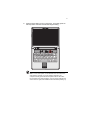
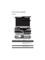
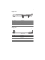
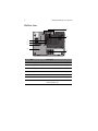
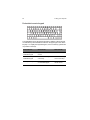
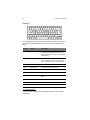
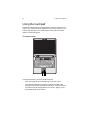
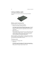
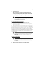
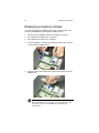
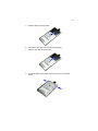
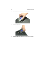
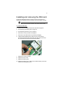
10 series
User Guide Notebook
English
dreamcom 10 series
Notebook
User Guide
Technical Support
Dreamcom Corporation
Tittwiesenstrasse 27
7000 Chur, Switzerland
Telephone: +41 81 300 43 50
Contact email: [email protected]
For additional information, please visit the Dreamcom Web site: www.dreamcom.ch
Copyright © 2008 Dreamcom Corporation
All Rights Reserved
dreamcom 10 series User Guide
Original Issue: March 2008
Changes may be made periodically to the information in this publication without obligation to notify
any person of such revision or changes. Such changes will be incorporated in new editions of this
manual or supplementary documents and publications. This company makes no representations or
warranties, either expressed or implied, with respect to the contents hereof and specifically
disclaims the implied warranties of merchantability or fitness for a particular purpose.
Record the model number, serial number, purchase date, and place of purchase information in the
space provided below. The serial number and model number are recorded on the label affixed to
your computer. All correspondence concerning your unit should include the serial number, model
number, and purchase information.
All other trademarks and registered trademarks are the properties of their respective companies.
vii
vii
x
1 Getting familiar with your computer
1
A tour of your computer
Top view
Closed top view
Left view
Right view
Rear view
Bottom view
Features
3
3
5
6
7
7
8
9
2 Using your computer
Using the display
Adjusting brightness
Switching the video image
Adjusting LCD height
Indicators
Using the keyboard
Identifying special keys
Using the touchpad
Using a battery pack
Battery pack characteristics
Optimizing battery life
Using the optical drive
Connecting peripherals
USB devices
External monitor
External keyboard
External pointing device
Printer
Audio devices
ExpressCard
Smart card
Docking station
Securing your computer
Security notch
Fingerprint recognition sensor
Passwords
13
15
15
15
16
18
19
19
24
26
26
29
32
34
34
34
35
35
35
35
35
36
37
38
38
38
38
Contents
Preface
Connecting the computer
Care and maintenance
iv
3 Software
Launch Manager
BIOS Utility
4 Replacing components
39
41
42
45
Installation precautions
ESD precautions
Pre-installation instructions
Post-installation instructions
Tool requirements
Removing the battery pack
Removing the lower cover
Replacing a memory module
Replacing the hard disk drive module
Installing and removing the SIM card
47
47
48
48
49
50
51
52
54
57
5 Moving with your computer
59
Disconnecting from the desktop
Moving around
Preparing the computer
What to bring to short meetings
What to bring to long meetings
Taking the computer home
Preparing the computer
What to bring with you
Special considerations
Setting up a home office
Traveling with the computer
Preparing the computer
What to bring with you
Special considerations
Traveling internationally with the computer
Preparing the computer
What to bring with you
Special considerations
6 Troubleshooting
Frequently-asked questions
Error messages
61
62
62
62
62
63
63
63
63
64
65
65
65
65
66
66
66
66
67
69
72
v
A Specifications
77
B Notices
81
Index
87
vi
vii
Preface
The dreamcom 10 notebook computer incorporates the latest mobile
technologies in a slim and portable package.
This manual should answer most of the questions you have about the dayto-day operation of your notebook computer. You should also take
advantage of the online help files that are available with almost all of the
programs shipped with your computer.
We hope you enjoy your notebook computer. With proper care, your
computer will provide you with years of productive service.
Connecting the computer
Connecting the computer is as easy as 1-2-3.
1.
Place the computer upside down on a flat, stable surface.
2.
Slide the battery cover latch toward the left (1), then remove the
battery cover (2).
1
2
viii
3.
Align the tabs on the battery pack with the grooves on the battery bay,
then insert the battery in place.
4.
Replace the battery cover. Make sure to slide the battery cover latch
forward to lock the battery cover.
Note: When using a battery pack for the first time, fully recharge the
battery, then disconnect the adapter to use up the battery before
recharging again. Perform this action twice to condition the battery
pack.
5.
Connect one end of the AC adapter to the DC-in port on the
computer’s rear panel.
6.
Connect the power cord to the AC adapter and the other end to a
properly grounded power outlet.
7.
Open the display by lifting up the cover then tilt it to a comfortable
viewing position.
Warning! Do not open the LCD display to more than 120° angle
when the computer is positioned at an angle of 10° to the
surface. Failure to do so may cause unit to tip over or fall and
cause serious injury.
The computer employs a microswitch that turns off the display (e.g.,
enters standby mode) to conserve power when you close the display
cover, and turns it back on when you open the display cover.
Caution: To avoid damaging the display, do not slam it when you
close it. Also, do not place any object on top of the computer when
the display is closed.
ix
8.
Press the power button to turn on the power. The POST (power-on
self-test) routine executes and Windows begins loading.
Note: To turn off the power, use the Windows Turn Off command to
shut down the computer. If you are unable to shut down your
computer normally, press and hold the power button for more than
four seconds to turn off the computer. If you turn off the computer and
want to turn it on again, wait at least two seconds before powering up.
x
Care and maintenance
Taking care of your computer
Your computer will serve you well if you take care of it.
•
Do not expose the computer to direct sunlight. Do not place it near
sources of heat, such as a radiator.
•
Do not expose the computer to temperatures below 0ºC (32ºF) or
above 50ºC (122ºF).
•
Do not subject the computer to magnetic fields.
•
Do not expose the computer to rain or moisture.
•
Do not spill water or any liquid on the computer.
•
Do not subject the computer to heavy shock and vibration.
•
Do not expose the computer to dust and dirt.
•
Never place objects on top of the computer to avoid damaging the
computer.
•
Never place the computer on uneven surfaces.
Taking care of your AC adapter
Here are some ways to take care of your AC adapter:
•
Do not connect the adapter to any other device.
•
Do not step on the power cord or place heavy objects on top of it.
Carefully route the power cord and any cables away from all potential
traffic.
•
When unplugging the power cord, do not pull on the cord itself but pull
on the plug.
•
The total ampere ratings of the equipment plugged in should not
exceed the ampere rating of the cord if you are using an extension
cord. Also, the total current rating of all equipment plugged into a
single wall outlet should not exceed the fuse rating.
xi
Taking care of your battery pack
Here are some ways to take care of your battery pack:
•
Use only batteries of the same kind as replacements. Turn the power
off before removing or replacing batteries.
•
Do not tamper with batteries. Keep them away from children.
•
Dispose of used batteries according to local regulations. Recycle if at
all possible.
Cleaning and servicing
When cleaning the computer, follow these steps:
1.
Power off the computer.
2.
Disconnect the AC adapter.
3.
Remove the battery pack.
4.
Use a soft cloth moistened with water. Do not use liquid or aerosol
cleaners.
Contact your dealer or see your service technician if any of the following
occurs:
•
The computer has been dropped or the body has been damaged.
•
Liquid has been spilled into the product.
•
The computer does not operate normally.
xii
1 Getting familiar with
your computer
This chapter gives an in-depth "tour" of the computer’s
many features.
3
A tour of your computer
Top view
1
19
2
18
3
17
16
15
14
13
4
5
6
7
8
12
9
11
10
#
Item
1
Web camera
Icon
Description
Enables you to communicate via video
with people over the Internet.
Note: The camera can only be used
when it is turned on.
2
Display screen
Also called LCD (liquid-crystal display),
displays computer output.
4
1 Getting familiar with your computer
#
Item
3
Indicators
Icon
Description
LEDs (light-emitting diodes) that turn on
and off to show the status of the
computer and its functions and
components.
For details on “Indicators” see page 18.
4
Fingerprint
recognition
sensor
Identifies the authorized fingerprint.
5
Power button
Turns on the computer power.
6
Mute button
Mutes the sound.
7
Bluetooth
button1
Enables or disables the Bluetooth
function.
8
Keyboard
Inputs data into your computer.
9
Touchpad
Touch-sensitive pointing device which
functions like a computer mouse.
For details on “Using the touchpad” see
page 24.
10,
11
Click buttons
(left and right)
The left and right buttons function like the
left and right mouse buttons.
12
Palm rest
Comfortable support area for your hands
when you use the computer.
WWAN button
Enables or disables the Wireless Wide
Area Network function.
13
(option)1
14
WLAN button1
Enables or disables the Wireless Local
Area Network function.
15
Skype end
Press to hang up or end a Skype call.
button2
16
17
Skype call
button2
Press to bring up the Skype window and
initiate a call over Skype.
Speakers
Built-in speakers for rich audio sound.
5
#
Item
Icon
Description
18
LCD slider
latch
Slide latch to the left to adjust the height
of the LCD.
19
Akustica digital
microphones
Internal microphones for sound
recording.
1
The Bluetooth, WWAN, and WLAN buttons are pre-set to run the wireless utility programs,
but can be reset by users. To set the Bluetooth, WWAN and WLAN buttons, run the
Launch Manager. See “Launch Manager” on page 41 for details.
2
Before you can use the Skype call and end buttons to place calls, you must have the
Skype software installed on your computer.You can also use the Launch Manager to set
both buttons to run applications.
Closed top view
1
2
#
Item
Description
1
LCD hinge arm
Supports the LCD.
2
LCD rails
Connects to the hinge arm and allows you to
adjust the height of the display in three height
increments to ensure correct ergonomic
position.
6
1 Getting familiar with your computer
Left view
1
2
3
4
5
7
Icon
6
#
Item
Description
1
DVI port
Connects to a DVI-compliant digital monitor or
an analog monitor using a DVI-VGA cable.
2
USB ports
Connect to USB devices (e.g., USB digital
camera).
3
Headphone-out
jack
Connects to headphone.
4
Microphone jack
Inputs sounds and voices into your computer.
5
Smart card slot
Accepts a smart card module.
6
ExpressCard
slot
Accepts on ExpressCard/34 module.
7
Infrared port
Interfaces with infrared devices (e.g. infrared
printer, IR-aware computer).
7
Right view
3
2
1
#
Item
Description
1
Optical drive
Accepts a CD or DVD.
2
LED indicator
Lights up when the optical drive is active.
3
Eject button
Press to eject the CD or DVD.
Rear view
1
2
3
#
Item
Description
1
Security keylock
Connects to a Kensington-compatible computer
security lock.
2
DC-in jack
Connects to an AC adapter.
3
Network jack
Connects to an Ethernet-based network.
8
1 Getting familiar with your computer
Bottom view
1
2
7
6
5
4
3
#
Item
Description
1
Docking alignment slots
Secures the computer to the docking station.
2
Docking connector
Connects the computer to a docking station.
3
HDD compartment
Houses the computer’s hard disk drive.
4
Battery cover
Remove cover to install the battery pack.
5
Battery cover latch
Locks and releases the battery cover.
6
Memory compartment
Houses the computer’s main memory.
7
SIM card compartment
Allows you to install a SIM (Subscriber
Identity Module) card.
9
Features
This computer was designed with the user in mind. Here are just a few of
its many features:
Performance
•
Intel® CoreTM 2 Duo mobile processor with 800 MHz FSB
•
15.4-inch Thin Film Transistor (TFT) LCD at 1680x1050 Wide Super
eXtended Graphics Array (WSXGA+) resolution displaying 16M colors
•
Memory upgradeable to 4 GB with 2 DDR2 soDIMM slots
•
Lithium-ion battery pack
•
Power management system
•
Dual view support
•
Simultaneous LCD and DVI display
•
External display (DVI) support up to 1680x1050 resolution at 16 M
colors
•
ATI Mobility Radeon X2600 with 256 MB VRAM VGA chipset,
supporting Microsoft DirectX® 9 and DirectX 10
Multimedia
•
AC’97 audio system with two 1.5W speakers
•
SoundBlaster-Pro and DirectSound compatible
Storage subsystem
•
High-capacity, enhanced-IDE hard disk (SATA interface)
•
Slot-in optical drive options:
•
DVD Dual drive
•
DVD Super Multi double-layer drive
•
Smart card slot
•
ExpressCard slot (ExpressCard/34 module)
10
1 Getting familiar with your computer
Communication
•
CMOS web camera with two Akustica digital microphones
•
Skype call and Skype end button
•
Wireless Local Area Network (WLAN): Intel PRO Wireless 4965AGN
Mini-PCI Express adapter
•
Wireless Personal Area Network (WPAN): Bluetooth v.2.0 adapter
•
Wireless Wide Area Network (WWAN): Sierra MC8775 PCI Express
MiniCard
Power subsystem
•
ACPI 3.0 CPU power management standard: supports standby (S3)
and hibernation (S4) power-saving modes
•
56 W 1900 mAh Li-ion battery pack
•
90 W 19 V AC adapter: Express charge 90% charge in 2 hours
Input devices
•
86-/87-keys, inverted “T” cursor layout
•
Seamless touchpad pointing device
•
12 function keys, four cursor keys, two Windows keys, hotkey controls,
embedded numeric keypad, and international language support
Connectivity
•
Ethernet port
•
Two USB 2.0 ports
•
IEEE 1394 (4-pin)
•
ExpressCard slot (ExpressCard/34 module)
•
Smart card slot
•
Infrared (IR) port
•
Monitor (DVI) port
•
Headphone/speaker/line-out jack
•
Microphone/line-in jack
•
DC-in jack for AC adapter
•
SIM card slot (internal)
11
Expansion
•
Upgradeable memory
•
Upgradeable hard disk
Security
•
Fingerprint recognition sensor
•
Trusted platform module (TPM)
•
BIOS passwords
Operating system and software
•
Microsoft Windows Vista Home Premium 64-bit
•
Microsoft Windows Vista Business 64-bit
•
Microsoft Windows Vista Ultimate 64-bit
•
Microsoft Windows Vista Enterprise 32-bit
Options and accessories
•
Li-ion battery pack
•
AC adapter
•
Docking station
12
1 Getting familiar with your computer
2 Using your
computer
This chapter contains the information you need to know
to operate the computer.
15
Using the display
The graphics display offers excellent viewing, display quality and desktopperformance graphics. The computer supports a large Thin-Film Transistor
(TFT) liquid crystal display (LCD) displaying up to 16 million colors at
1680x1050 WSXGA+ resolution.
The power management system incorporates an "automatic LCD dim"
feature that automatically dims the LCD when the computer is powered by
a battery pack to conserve battery power. See “Power management” on
page 31 for more information on power management features.
Adjusting brightness
You can conserve power by setting the brightness to the lowest
comfortable setting by pressing <Fn> and the <F3> or <F4> key on the
keyboard.
To adjust the display brightness:
•
Press <Fn> + <F3> to decrease brightness of the display screen.
•
Press <Fn> + <F4> to increase brightness of the display.
Switching the video image
The computer’s crisp display and multimedia capabilities are great for
viewing movies or giving presentations. If you prefer, you can also connect
an external monitor when giving presentations. This computer supports
simultaneous LCD and external display output via the external display port.
Simultaneous display allows you to control the presentation from your
computer and at the same time face your audience. You can also connect
other output display devices such as LCD projection panels for largeaudience presentations.
To switch the video image between internal and external monitor:
Press <Fn> + <F2> to switch the video image between the display screen,
external monitor (if connected) and both the display screen and external
monitor.
16
2 Using your computer
Adjusting LCD height
The computer’s LCD hinge arm allows you to adjust the height of the LCD
monitor from 56.7 mm (2.2 inch), 85.7 mm (3.4 inch), and 114.7 mm (4.5
inch) in 29 mm (1.1 inch) increments.
To adjust the LCD height:
Slide the LCD slider latch to the left (1) and pull the display panel to the
desired height (2).
17
To return to its average height, slide the LCD slider latch to the left (1), then
push down the display panel (2).
Warning! When sliding down the LCD display back to its average
height, be sure to keep fingers away from the grap of the LCD
hinge arm and the slider latch to avoid risk of injury.
Keep fingers
away from the
gap as you
slide the LCD
display down.
Keep fingers
away from the
gap as you
slide the LCD
display down.
18
2 Using your computer
Indicators
The computer has six easy-to-read status indicators (LEDs) under the
display screen.
1
Icon
2
3 4
5
6
#
Indicator
Description
1
Skype call
Lights when a Skype call is in progress.
2
Docking
indicator
Lights when the computer is properly connected to
the docking station.
For more information on how to use the dreamcom
10 docking station, refer to the documentation that
came with the docking station.
3
Caps lock
Lights up when Caps Lock is activated.
4
Num lock
Lights up when Numeric Lock is activated.
5
Power
Indicates the computer power status.
The indicator blinks when the computer is in
standby mode.
6
Charge
Indicates the computer’s battery is being charged.
The indicator light goes off when the battery is fully
charged.
19
Using the keyboard
The keyboard has full-sized keys with an embedded keypad, separate
cursor keys, two Windows keys and twelve function keys.
Identifying special keys
Lock keys
1
2
Fn
The keyboard has three lock keys which you can toggle on and off.
#
Lock Key
Description
1
Scroll Lock
When Scroll Lock is on, the screen moves one line up or
down when you press ↑ or ↓ respectively. Scroll Lock does
not work with some applications.
Num Lock
Press the Fn - Scroll Lock key to turn Num Lock on. When
Num Lock is on, the embedded keypad is in numeric mode.
The keys function as a calculator (complete with the
arithmetic operators +, -, *, and /). Use this mode when you
need to do a lot of numeric data entry. A better solution
would be to connect an external keypad.
Caps Lock
When Caps Lock is on, all alphabetic characters typed are
in uppercase.
2
20
2 Using your computer
Embedded numeric keypad
7
8
4
9
5
1
2
0
6
x
3
–
,
+
The embedded numeric keypad functions like a desktop numeric keypad.
It is indicated by small characters located on the upper right corner of the
keycaps. To simplify the keyboard legend, cursor-control key symbols are
not printed on the keys.
Desired Access
Num Lock On
Num Lock Off
Number keys on
embedded keypad
Type numbers in a normal
manner.
Cursor-control keys on
embedded keypad
Hold Shift while using cursorcontrol keys.
Hold Fn while using
cursor-control keys.
Main keyboard keys
Hold Fn while typing letters
on embedded keypad.
Type the letters in a
normal manner.
21
Windows keys
2
1
The keyboard has two keys that perform Windows-specific functions.
#
Key
Description
1
Application key
Opens the application’s context menu (same as
right-click).
2
Windows logo key
Start button. Combinations with this key perform
special functions. Below are a few examples:
+ Tab (Activates next Taskbar button)
+ E (Explores My Computer)
+ F (Finds Document)
+ M (Minimizes All)
Shift +
+ M (Undoes Minimize All)
+ R (Displays Run dialog box)
22
2 Using your computer
Hotkeys
F1
F2
F3
F4
F5
F6
F7
F8
F9
F10
F11 F12
Fn
The computer uses hotkeys or key combinations to access controls such
as screen contrast and brightness, volume output and the BIOS setup
utility.
Hotkey
Function
Description
Fn-F1
Sleep
Puts the computer in Sleep mode, which can
be defined via the advanced section of the
Power Management Properties in the Windows
Control Panel.
Fn-F2
Display toggle
Switches display output between the display
screen, external monitor (if connected) and
both the display screen and external monitor
Fn-F3
Brightness down
Decreases the screen brightness.
Fn-F4
Brightness up
Increases the screen brightness.
Fn-F7
Volume down
Decreases the speaker volume.
Fn-F8
Volume up
Increases the speaker volume.
Fn-F9
Play/pause
Plays, pauses, or resumes an audio CD or
DVD.
Fn-F10
Stop
Stops CD or DVD playback.
Fn-F11
Backward
Skips to previous track/chapter.
Fn-F12
Forward
Skips to next track/chapter.
To activate hotkeys:
Press and hold the Fn key before pressing the other key in the hotkey
combination.
23
Euro symbol
If your keyboard layout is set to United States-International or United
Kingdom or if you have a keyboard with a European layout, you can type
the Euro symbol on your keyboard.
Alt Gr
Note for US keyboard users: The keyboard layout is set when you
first set up Windows. For the Euro symbol to work, the keyboard
layout has to be set to United States-International.
To type the Euro symbol:
1.
Locate the Euro symbol on your keyboard.
2.
Open a text editor or word processor.
3.
Hold Alt Gr and press the Euro symbol.
Note: Some fonts and software do not support the Euro symbol.
Please refer to (www.microsoft.com/typography/
EuroSymbolFAQ.mspx) for more information.
24
2 Using your computer
Using the touchpad
The built-in touchpad is both a pointing device that senses movement on its
surface. This means the cursor responds as you move your finger on the
surface of the touchpad. The central location on the palm rest provides
optimum comfort and support.
Touchpad basics
1 2 3
The following teaches you how to use the touchpad:
•
Move your finger across the touchpad (2) to move the cursor.
•
Press the left (1) and right (3) buttons located on the edge of the
touchpad to do selection and execution functions. These two buttons
are similar to the left and right buttons on a mouse. Tapping on the
touchpad produces similar results.
25
Function
Left button
Execute
Click twice
quickly.
Tap twice (at the same speed as
double-clicking the mouse button).
Select
Click once.
Tap once.
Drag
Click and
hold, then
use finger to
drag the
cursor on
the
touchpad.
Tap twice (at the same speed as
double-clicking the mouse button)
and hold finger to the touchpad on
the second tap to drag the cursor.
Access
context
menu
Right button
Tap
Click once.
Note: Keep your fingers dry and clean when using the touchpad.
Also keep the touchpad dry and clean. The touchpad is sensitive to
finger movements. Hence, the lighter the touch, the better the
response. Tapping too hard will not increase the touchpad’s
responsiveness.
26
2 Using your computer
Using a battery pack
The computer uses a battery pack that gives you long use between
charges.
Battery pack characteristics
The battery pack has the following characteristics:
•
Employs current battery technology standards
The computer uses a Lithium-ion battery pack which does not have the
memory effect problem of Nickel Cadmium (NiCd) batteries. Li-ion
batteries consistently provide the longest battery life, best-suited for
road warriors.
•
Battery-low warning
When the battery charge level becomes low, the status indicator of the
computer flashes at regular intervals. This tells you that the battery
power is critically low (and you should save your work). You can
correct this situation by recharging the battery pack.
Whenever possible, use the AC adapter. The battery will come in handy
when you travel or during a power failure. It is advisable to have an extra
fully-charged battery pack available as backup.
Charging modes
The adapter has two charging modes:
•
Rapid mode
The computer uses rapid charging when power is turned off and a
powered AC adapter is connected to it. In rapid mode, a fully depleted
battery gets 95% charged in approximately 2 hours.
27
•
Charge-in-use mode
When the computer is in use with the AC adapter plugged in, the
computer also charges the battery pack if installed. This mode will
take longer to fully charge a battery than rapid mode. In charge-in-use
mode, a fully depleted battery gets 95% charged in approximately 2.5
to 4.5 hours.
Note: We suggest that you charge the battery pack before retiring for
the day, letting it charge overnight before traveling. This ensures a
fully charged battery for use the next day.
To use a battery pack for the first time:
When using a battery pack for the first time, follow these steps:
1.
Connect the AC adapter to a power source and to the computer and
fully recharge the battery.
2.
Disconnect the adapter to use up the battery before recharging again.
You only need to do this once or twice with a new battery or with a battery
that's been stored without being used for a long time. If the computer is to
be stored for more than two weeks, we suggest you remove the battery
pack. Battery power from a fully charged battery pack depletes in roughly a
day with the computer in Standby mode, a month in Hibernation mode or
when power is off.
Warning! Do not expose battery packs to temperatures below 0ºC
(32ºF) or above 60ºC (140ºF). This may adversely affect the
battery pack.
To install the battery pack:
Important! Before removing the battery pack, make sure that you
have an AC adapter connected to the computer; otherwise, turn off
the computer.
1.
Place the computer upside down on a flat, stable surface.
28
2 Using your computer
2.
Slide the battery cover latch forward, then remove the battery cover.
3.
Align the tabs on the battery pack with the grooves on the rear side of
the computer, then insert the battery in place.
4.
Replace the battery cover. Make sure to slide the battery cover latch
forward to lock the battery cover.
To remove the battery pack:
See “Removing the battery pack” on page 50 for detailed instructions.
To charge the battery:
To charge the battery, install the battery pack and plug the AC adapter into
the computer and an electrical outlet.
To check the battery level:
The Windows battery meter indicates the present battery level. Simply rest
your cursor on the battery meter (or AC plug) icon on the taskbar to see the
present charge level of your battery.
29
Optimizing battery life
This section helps you get the most out of battery operation. Optimizing
battery life prolongs the charge/recharge cycle and improves recharge
efficiency. Follow these suggestions to optimize and maximize battery
power:
•
Purchase an extra battery pack.
•
Use the AC adapter whenever possible so that the battery is reserved
for on-the-go computing.
•
Keep the battery pack in the computer powered by the AC adapter.
The constant trickle charge maintains the battery level to eliminate the
battery self-discharge effect. The charge-in-use function also charges
the battery pack.
•
Eject the PC card from the card slot when it is not in use, since the PC
card draws extra power.
•
Store the battery pack in a cool, dry place. The recommended storage
temperature for battery packs ranges from 10 to 30 ° C. The higher
the storage temperature, the faster the battery pack self-discharges.
•
The batteries can be recharged about 400 times when used as
directed. Excessive recharging decreases battery life.
•
Take care of your battery pack and AC adapter. See “Care and
maintenance” on page x of the preface.
Battery-low warning
You never have to worry about battery power as long as you are using the
AC adapter. However, when you operate the computer on battery power,
pay extra attention to the power indicator on the display panel.
During a battery-low condition, the power indicator flashes at regular
intervals until battery power is depleted.
Warning! Connect the AC adapter to the computer as soon as
possible. Data is lost when computer power is cut off during
Standby mode.
30
2 Using your computer
The following table shows the recommended course of action to take when
you encounter a battery-low condition.
Situation
Recommended Action
AC adapter and
power outlet
available
1. Connect the AC adapter to the computer.
2. Save all necessary files.
3. Resume work.
Power off the computer if you wish to recharge the battery
rapidly.
An extra fullycharged battery
pack available
1. Save all necessary files.
2. Exit the application.
3. Power off the computer.
4. Replace the battery pack.
5. Power on the computer and resume work.
AC adapter or
power outlet not
available
1. Save all necessary files.
2. Exit the application.
3. Power off the computer.
31
Power management
This computer has a built-in power management unit that monitors system
activity. System activity refers to any activity involving one or more of the
following devices: keyboard, mouse, floppy drive, hard disk, peripherals
connected to the serial and parallel ports, and video memory. If no activity
is detected for a period of time (called an inactivity timeout), the computer
stops some or all of these devices in order to conserve energy.
This computer employs a power management scheme that supports ACPI
(Advanced Configuration and Power Interface) which allows for maximum
power conservation and maximum performance at the same time.
Windows handles all power-saving chores for your computer.
Advanced Configuration and Power Interface
Advanced Configuration and Power Interface (ACPI) is a power
management specification jointly developed by Compaq, Intel, Microsoft,
Phoenix and Toshiba. ACPI enables Windows to control the amount of
power given to each device attached to the computer. With ACPI,
Windows can turn off peripheral devices when they are not in use, thereby
saving power.
Note: We recommend you enable power management to prolong
your battery life.
Refer to Windows help for more details.
32
2 Using your computer
Using the optical drive
Your computer comes with a slot-in type optical drive providing portable
multimedia access. The drive allows you to watch DVD movies, and the
combo drive, in addition, lets you burn your data onto a CD recordable disc.
Caution: Never insert 8 cm discs into the computer’s slot-in optical
drive. Only 12 cm discs are supported.
To insert a disc:
Keep disc flat, then align and insert the disc into the slot with the label
facing upwards. The drive will begin reading data from the disc.
To remove a disc:
Before ejecting a disc, make sure that no programs or applications are
using the disc. Then press the eject button to eject the disc.
To play DVD movies:
Insert a DVD movie disc into the drive and the DVD movie will
automatically play after a few seconds.
Important! When you launch the DVD player for the first time, the
program asks you to input the region code. DVD discs are divided
into 6 regions. Once your DVD drive is set to a region code, it will play
DVD discs of that region only. You can set the region code a
maximum of five times (including the first time), after which the last
region code set will remain permanent. Recovering your hard disk
does not reset the number of times the region code has been set.
Refer to the table below for DVD movie region code information.
Region code
Country or region
1
U.S.A., Canada
2
Europe, Middle East, South Africa, Japan
3
Southeast Asia, Taiwan, Korea (South)
4
Latin America, Australia, New Zealand
5
Former U.S.S.R., parts of Africa, India
33
Region code
Country or region
6
People's Republic of China
Note: To change the region code, insert a DVD movie of a different
region into the DVD drive. Please refer to the online help for more
information.
To burn CDs and DVDs:
Your computer comes with a slot-in DVD Dual or DVD Super-Multi drive,
allowing you to burn DVDs and CDs on your computer. Refer to the online
help of the DVD or CD recording software on your hard disk for more
information.
34
2 Using your computer
Connecting peripherals
Your computer offers excellent expansion capabilities with its built-in ports,
connectors and bays. This section describes how to make connections
through various options. When connecting peripherals, read the manual
included with the peripheral for operating instructions.
USB devices
The two USB (Universal Serial Bus) 2.0 ports on the computer allow you to
connect peripherals without occupying too many resources. USB 2.0 is the
second generation USB standard that allows faster transfer rates and is
also backward-compatible with USB 1.1 devices. Common USB devices
include a mouse, keyboard, and digital camera.
Before disconnecting a USB device from your computer, click on the Safely
Remove Hardware icon on the taskbar and click on the device. When the
device can be safely removed, disconnect the device from the computer.
See your peripheral's documentation for details.
External monitor
You can connect an external monitor to the DVI port on the left panel. The
DVI port allows you to connect a digital monitor directly. To connect an
analog monitor, use a DVI-VGA cable connector. Read the monitor manual
for additional instructions.
Note: If an external monitor is not connected, closing the display
cover puts the computer into Standby mode.
To use simultaneous display:
Your computer takes advantage of Windows multi-display capability,
allowing you to use your computer for presentation purposes. So whatever
is displayed in your computer will likewise be displayed on the other
external display.
Connect an external display device to the DVI port. You can then toggle
the display output location by pressing Fn-F2 to make the image appear on
both the computer LCD and external display device.
35
External keyboard
This computer has a keyboard with full-sized keys and an embedded
keypad. If you feel more comfortable using a desktop keyboard, you can
connect a USB external keyboard to an available USB port.
External pointing device
This computer accepts a USB mouse or a similar pointing device. Simply
plug it into an available USB port.
Printer
You can connect a USB printer to an available USB port. See your printer
manual for operating instructions.
Audio devices
Audio devices are easy to connect to the audio ports accessible on the
front of the computer. You can plug an external microphone (or an audio
line-in device) into the line-in jack. Amplified speakers or headphones
connect to the headphone-out jack. The line-in and line-out jack on the
docking station also supports digital audio devices (S/PDIF).
ExpressCard
The ExpressCard slot found on the left panel of the computer accepts
credit-card-sized cards that enhance the usability and expandability of the
computer.
ExpressCard standard was developed by a large number of PCMCIA
member companies including technology leaders, system manufacturers,
card manufacturers, and representatives from all other parts of the PC
Card industry as the next generation of ‘plug-in’ I/O cards. The
ExpressCard standard supports both the USB 2.0 and PCI Express
interfaces.
Note: Refer to your card’s manual for details on how to install and
use the card and its functions.
36
2 Using your computer
To insert an ExpressCard:
1.
Hold the card label-side up with the card facing the computer.
2.
Slide the card into the slot until it is seated.
To remove an ExpressCard:
Before ejecting a card:
•
Exit the application using the card.
•
Left-click on the Safely Remove Hardware icon on the taskbar and
stop the card operation.
1.
Gently press the ExpressCard module further into the ExpressCard
slot to pop it out.
2.
Pull out the ExpressCard module from the ExpressCard slot.
Smart card
The Smart card slot on the left panel of the computer accepts credit-cardsized cards that enhance the usability and expandability of the computer.
A smart card is engineered to be tamper resistant. The card is embedded
with a microchip for security that can store passwords, certificates, and
keys. The microchip can be loaded with data and applications to identify
and authenticate a user when making electronic cash payments, telephone
calls on a public telephone, parking meter payments, etc.
Note: Refer to your card’s manual for details on how to install and
use the card and its functions.
To insert a Smart card:
1.
Hold the card with the gold chip facing up and aligned with the slot.
2.
Slide the card into the slot until it is seated.
To remove a Smart card:
Before ejecting a card:
•
Exit the application using the card.
•
Left-click on the Safely Remove Hardware icon on the taskbar and
stop the card operation.
37
1.
Gently press the card module further into the Smart card slot to pop it
out.
2.
Pull out the Smart card module from the slot.
Docking station
The docking station transforms the dreamcom 10 into a full-featured
desktop workstation. See your docking station user guide for operating
instructions.
38
2 Using your computer
Securing your computer
Security features include hardware and software locks — a security notch,
fingerprint recognition sensor, and password.
Security notch
A security notch located on the rear panel of the computer lets you connect
a Kensington-compatible computer security lock.
Wrap a computer security lock cable around an immovable object such as
a table or locked drawer handle. Insert the lock into the notch and turn the
key to secure the lock. Some keyless models are also available. See “Rear
view” on page 7 for the location of this notch.
Fingerprint recognition sensor
A fingerprint recognition sensor is located beside the power button. See
“Top view” on page 3 for the location of this sensor. This security feature
allows only an authorized user to access the computer. For more details
see the related documentation that comes with your computer.
Passwords
Passwords protect your computer from unauthorized access. When set,
no one can access the computer without entering the correct password.
There are three types of passwords you can set:
•
Supervisor Password secures your computer against unauthorized
entry to critical parameters in the BIOS Utility.
•
User Password secures your computer against unauthorized use, and
allows limited access to the BIOS Utility.
•
Hard Disk Password protects your data by preventing unauthorized
access to your hard disk (even if the hard disk is physically removed
from the computer and installed in another computer).
See “About passwords” on page 43 for details.
Important: Do not forget your Setup and Hard Disk password! If you
forget your password, please get in touch with your dealer or an
authorized service center.
3 Software
This chapter discusses the important system
utilities bundled with your computer.
41
Launch Manager
The Launch Manager allows you to set the Bluetooth, WWAN, WLAN,
Skype call, and Skype end buttons; located above the keyboard, to run
other programs.
You can access the Launch Manager by clicking on Start, All Programs,
and then Launch Manager. Pressing on an unassigned launch key also
brings up the Launch Manager.
42
3 Software
BIOS Utility
The BIOS Utility is a hardware configuration program built into your
computer’s BIOS (Basic Input/Output System).
Your computer is already properly configured and optimized, and you do
not need to run this utility. However, if you encounter configuration
problems, you may need to run it. Please also refer to Chapter 5,
Troubleshooting when a problem arises.
To activate the BIOS Utility, press F2 during POST.
Navigating the BIOS Utility
The main menu items are the following:
•
Information - displays a summary of the computer’s hardware
information.
•
Main - contains basic settings about your computer such as date, time,
and boot options.
•
Advanced - allows you to view and configure your drives, and I/O
(input/output) ports.
•
Security - lets you set passwords for protecting your computer.
•
TPM State - lets you view and configure the TPM (Trusted Platform
Module) services.
•
Boot - allows you to set the order in which the system boots up.
•
Exit - includes options to save or discard your changes, and to exit the
BIOS Utility.
Note: Certain parameters are highly technical. Do not make changes
to parameters if you do not understand the function of the particular
parameter.
To enter a menu, highlight the item using the ← → keys. Within a menu,
navigate through the BIOS Utility by following these instructions:
•
Press the cursor up/down keys (↑↓) to select item.
•
Press the F5 or F6 to change the value of a parameter.
•
Press Enter to go into a sub-menu.
•
Press Esc while you are in any of the menus to go one menu level
higher.
43
Note: You can change the value of a parameter if it is enclosed in
square brackets. Navigation keys for a menu are shown at the bottom
of the screen. Please refer to the help information that displays on the
Item Specific Help pane of the BIOS Utility as you select a parameter.
For optimum settings, press F9 to load setup defaults; then press F10 to
save the changes and exit the BIOS Utility.
Note: Don’t forget your password. If you forget your password,
you may have to return your notebook computer to your dealer to
reset it.
About passwords
You can set, change or remove passwords in the Security menu.
Setting a password
Follow these steps:
1.
Use the ↑ and ↓ keys to highlight a password parameter (Supervisor or
User) and press the Enter key. The password box appears:
2.
Type a password in the Enter New Password field. The password may
consist of up to eight alphanumeric characters (A-Z, a-z, 0-9). Press
Enter.
Important: Be very careful when typing your password because the
characters do not appear on the screen.
3.
Re-enter the password in the Confirm New Password field, and press
Enter.
4.
Press Enter to accept the changes and save the password.
44
3 Software
Changing or removing a password
Follow these steps:
1.
Use the ↑ and ↓ keys to highlight a password parameter and press
Enter. The following box appears.
2.
Enter the current password, then press Enter.
•
To change the password, type in a new password in the Enter
New Password field and press Enter. Then re-enter the
password in the Confirm New Password field and press Enter.
•
To remove the password, press Enter twice (once each in the
Enter New Password and Confirm New Password fields) without
typing anything in the fields.
Press Enter to accept the changes.
About the boot drive sequence
In the Boot menu, use the cursor up/down keys (↑↓) to select a boot
device, then press F5 or F6 to change its order. Items with a “+” sign can
be further expanded.
4 Replacing
components
This chapter discusses the precautionary measures
and installation procedures you need to know to
upgrade the computer.
47
Installation precautions
Before you remove or replace any component, we recommend that you
read the following sections. These sections contain important ESD
precautions along with pre-installation and post-installation instructions.
ESD precautions
Electrostatic discharge (ESD) can damage the processor, disk drives,
mainboard, memory modules, and other notebook components. Always
observe the following precautions before you install a server component.
•
Do not remove a component from its protective packaging until you are
ready to install it.
•
Do not touch the component pins, leads, or circuitry.
•
Components with a Printed Circuit Board (PCB) assembly should
always be laid with the assembly-side down.
•
Wear a wrist grounding strap and attach it to a metal part of the
computer before handling components. If a wrist strap is not available,
maintain contact with the computer throughout any procedure
requiring ESD protection.
•
Keep the work area free of nonconductive materials, such as ordinary
plastic assembly aids and foam packing.
48
4 Replacing components
Pre-installation instructions
Perform the steps below before you open the notebook computer or before
you remove or replace any component.
Warning! Failure to properly turn off the computer before you
start installing components may cause serious damage.
1.
Turn off power to the system and all peripherals.
2.
Unplug the AC adapter and all power and signal cables from the
system.
3.
Place the system on a flat, stable surface.
4.
Open the system according to the instructions on page 51.
5.
Follow the ESD precautions described in this section when handling
any component.
Post-installation instructions
1.
Perform the steps below after installing any component.
2.
See to it that all components are installed according to the described
step-by-step instructions.
3.
Reinstall all hardware structure or cable that have been previously
removed.
4.
Reinstall the lower cover.
5.
Reconnect the necessary cable.
6.
Turn on the system.
49
Tool requirements
We recommend that you have the following tools ready.
•
Flathead screwdriver (2.4mm)
•
Phillips screwdriver (#00, #0, or #1)
•
Plastic flathead screwdriver
50
4 Replacing components
Removing the battery pack
1.
Turn the base unit over.
2.
Slide the battery cover latch forward, then remove the battery cover.
3.
Gently pull on the tape attached to the battery and lift the battery out.
51
Removing the lower cover
1.
See “Removing the battery pack” on page 50.
2.
Remove the eight screws on the lower cover.
3.
Use a plastic screwdriver to pry open the lower cover.
4.
Remove the lower cover from the main unit.
52
4 Replacing components
Replacing a memory module
The computer supports two DIMM sockets. Each socket supports 1 GB,
2 GB, and 4 GB DDR2-667 (PC2-5300) So-DIMM modules.
1.
Perform the pre-installation instructions described on page 48.
2.
See “Removing the battery pack” on page 50.
3.
See “Removing the lower cover” on page 51.
4.
Use your fingertips or a plastic flat screwdriver to push out the latches
on each side of the DIMM socket.
5.
Grasp the edges of the module then gently pull the module out of the
DIMM socket.
Note: Hold DIMMs only by the edges. Do not touch the components
or gold edge connectors. Install DIMMs with gold-plated edge
connectors only.
53
6.
Align the notch in the memory module with the tab in the DIMM socket.
7.
Slide the module firmly into the slot at a 45° angle and press the
module downward until the clips lock in place.
8.
Replace the lower cover.
54
4 Replacing components
Replacing the hard disk drive module
Note: Before performing any hardware upgrade, protect your data by
backing up your existing hard disk drive (HDD) before installing a new
hard drive.
1.
Perform the pre-installation instructions described on page 48.
2.
See “Removing the battery pack” on page 50.
3.
Gently pull on the tape attached to the HDD and slide the module out
of its bay.
4.
Remove the two screws that secure the HDD to the bracket.
55
5.
Slide the HDD out of the bracket.
6.
Remove the new HDD from its protective packaging.
7.
Slide the new HDD into the bracket.
8.
Secure the HDD to the bracket with the two screws you removed
earlier.
56
9.
4 Replacing components
Slide the HDD module into the bay until it is fully seated.
10. Replace the battery pack.
11. Replace the battery cover. Make sure to slide the battery cover latch
forward to lock the battery cover.
57
Installing and removing the SIM card
The built-in SIM feature allows for wireless access to the Internet via
dreamcom 10, wherever you are; as long as you’ve got cellular coverage.
Note: Follow instructions provided by the network service provider.
To install the SIM card:
1.
Perform the pre-installation instructions described on page 48.
2.
See “Removing the battery pack” on page 50.
3.
See “Removing the lower cover” on page 51.
4.
Remove the memory modules. See page 52.
5.
Remove the new SIM card from its protective packaging.
6.
Hold the SIM card label-side up with the card connector facing
downward and the beveled corner fitting the upper-left corner of the
slot, then slide the card into the slot until it is seated.
7.
Replace the memory modules.
8.
Replace the lower cover.
9.
Replace the battery pack.
10. Replace the battery cover. Make sure to slide the battery cover latch
forward to lock the battery cover.
58
4 Replacing components
To remove the SIM card:
1.
Perform the pre-installation instructions described on page 48.
2.
See “Removing the battery pack” on page 50.
3.
See “Removing the lower cover” on page 51.
4.
Remove the memory modules. See page 52.
5.
Gently press the SIM card module further into the slot to pop it out.
6.
Pull out the SIM card from the slot.
7.
Replace the lower cover.
8.
Replace the battery pack.
9.
Replace the battery cover. Make sure to slide the battery cover latch
forward to lock the battery cover.
5 Moving with your
computer
This chapter gives you tips and hints on things to
consider when moving around or traveling with
your computer.
61
Disconnecting from the desktop
Follow these steps to disconnect your computer from external accessories:
1.
Save your work in progress.
2.
Shut down the operating system.
3.
Turn off the computer.
4.
Disconnect the cord from the AC adapter.
5.
Disconnect the keyboard, pointing device, printer, external monitor,
and other external devices.
6.
Disconnect the Kensington lock if you are using one to secure the
computer.
62
5 Moving with your computer
Moving around
when you are just moving within short distances, for example, from your
office desk to a meeting room
Preparing the computer
Before moving the computer, close and latch the display cover to place it in
Standby mode. You can now safely take the computer anywhere you go
within the building.
To bring the computer out of Standby mode, open the display and press
the power button.
What to bring to short meetings
A fully charged battery runs the computer for 4 hours under most
circumstances. If your meeting is shorter than that, you probably do not
need to bring anything with you other than the computer.
What to bring to long meetings
If your meeting will last longer than 4 hours or if your battery is not fully
charged, you may want to bring the AC adapter with you to plug in your
computer in the meeting room.
If the meeting room does not have an electrical outlet, reduce the drain on
the battery by putting the computer in sleep mode. Press Fn-F1 or close
the display cover whenever you are not actively using the computer. Then
press the power button to resume (open the display if necessary)
63
Taking the computer home
when you are moving from your office to your home or vice versa
Preparing the computer
After disconnecting the computer from your desktop, follow these steps to
prepare the computer for the trip home:
1.
Remove all media from the drives. Failure to remove the media can
damage the drive head.
2.
Pack the computer in a protective case that can prevent the computer
from sliding around and cushion it if it should fall.
Caution: Avoid packing items next to the top cover of the computer.
Pressure against the top cover could damage the screen.
What to bring with you
Unless you already have some items at home, bring the following items
with you:
•
AC adapter and power cord
•
The printed user manual
Special considerations
Follow these guidelines to protect your computer while traveling to and
from work:
•
Minimize the effect of temperature changes by keeping the computer
with you.
•
If you need to stop for an extended period of time and cannot bring the
computer with you, leave the computer in the trunk of the car to avoid
exposing the computer to excessive heat.
•
Changes in temperature and humidity can cause condensation. Allow
the computer to return to room temperature, and inspect the screen for
condensation before turning on the computer. If the temperature
change is greater than 18°F (10°C), allow the computer to come to
room temperature slowly. If possible, leave the computer for 30
minutes in an environment with a temperature between outside and
room temperature.
64
5 Moving with your computer
Setting up a home office
If you frequently work on your computer at home, it may be worthwhile to
purchase a second AC adapter for use at home. With a second AC
adapter, you can avoid transporting the extra weight to and from home.
If you use your computer at home for significant periods of time, you might
also want to add an external keyboard, monitor, or mouse.
65
Traveling with the computer
when you are moving within a larger distance, for instance, from your office
building to a client’s office building or traveling locally
Preparing the computer
Prepare the computer as if you were taking it home. Be sure the battery in
the computer is charged. Airport security may require you to turn on your
computer when bringing it into the gate area.
What to bring with you
Bring the following items with you:
•
AC adapter
•
Spare, fully charged battery packs
•
Additional printer driver files if you plan to use another printer
Special considerations
In addition to the guidelines for taking the computer home, follow these
guidelines to protect your computer while traveling:
•
Always take the computer as carry-on luggage.
•
If possible, have the computer inspected by hand. The computer can
safely pass through security X-ray machines, but never expose the
computer to a metal detector.
•
Avoid exposing floppy disks to hand-held metal detectors.
66
5 Moving with your computer
Traveling internationally with the
computer
when you are moving from country to country
Preparing the computer
Prepare the computer as you would normally prepare it for traveling.
What to bring with you
Bring the following items with you.
•
AC adapter
•
Power cords that are appropriate to the country to which you are
traveling
•
Spare, fully charged battery packs
•
Additional printer driver files if you plan to use another printer
•
Proof of purchase, in case you need to show it to customs officials
•
International Travelers Warranty passport
Special considerations
Follow the same special considerations as when traveling with the
computer. In addition, these tips are useful when traveling internationally.
•
When traveling in another country, check that the local AC voltage and
the AC adapter power cord specifications are compatible. If not,
purchase a power cord that is compatible with the local AC voltage
(e.g., power rating). Do not use converter kits sold for appliances to
power the computer.
•
If you are using the modem, check if the modem and connector is
compatible with the telecommunication system of the country you are
traveling in.
6 Troubleshooting
This chapter instructs you on how to deal with
common system problems. Read it before calling
a technician if a problem occurs. Solutions to
more serious problems require opening up the
computer. Do not attempt to open and service the
computer by yourself. Contact your dealer or an
authorized service center for assistance.
69
Frequently-asked questions
This is a list of possible situations that may arise during the use of your
computer, and it gives easy answers and solutions to these questions.
I press the power button, but the computer does not start or
boot-up.
Look at the power indicator:
•
•
If it is not lit, no power is being applied to the computer. Check the
following:
•
If you are running on battery power, it may be low and unable to
power the computer. Connect the AC adapter to recharge the
battery pack.
•
Make sure the AC adapter is plugged in properly to the computer
and to the power outlet.
If it is lit, check the following:
•
If the power indicator is lit, power is being applied to the computer.
•
If the power indicator is blinking, the computer is in standby mode.
Press the power button to resume.
•
Is a non-bootable (non-system) diskette in the floppy drive?
Remove or replace it with a system diskette and press Ctrl-Alt-Del
to restart the system.
The operating system files may be damaged or missing. Insert the startup
disk you created during Windows setup into the floppy drive and press CtrlAlt-Del to restart the system. This will diagnose your system and make
necessary fixes.
Nothing appears on the screen.
The computer’s power management system automatically blanks the
screen to save power. Press any key to turn the display back on.
If pressing a key does not turn the display back on, two things might be the
cause:
•
The brightness level might be too low. Press Fn-F3 and Fn-F4 to
adjust the brightness level.
•
The display device might be set to an external monitor. Press the
display toggle hot key Fn-F2 to toggle the display back to the
computer.
70
6 Troubleshooting
Image is not full-screen.
Make sure the resolution is set to a resolution your system supports. Rightclick on your Windows desktop and select Properties to bring up the
Display Properties dialog box. Then click on the Settings tab to make sure
the resolution is set to the appropriate resolution. Resolutions lower than
the specified resolution are not full-screen on the computer or on an
external monitor.
No audio from the computer.
Check the following:
•
The volume may be muted. In Windows, look at the volume control
icon on the taskbar. If it is crossed-out, click on the icon and deselect
the Mute option.
•
The speakers may be turned off. Press the mute button.
•
The volume level may be too low. Press Fn-F7 and Fn-F8 to adjust
the brightness level. In Windows, look at the volume control icon on
the taskbar. Click on the icon and adjust the level.
If headphones, earphones or external speakers are connected to the lineout port on the computer’s left panel, the internal speakers automatically
turn off.
The keyboard does not respond.
Try attaching an external keyboard to the USB connector on the computer.
If it works, contact your dealer or an authorized service center as the
internal keyboard cable may be loose.
The printer does not work.
Check the following:
•
Make sure that the printer is connected to a power outlet and it is
turned on.
•
Make sure the printer cable is connected securely to the computer’s
USB port and the corresponding port on the printer.
71
I want to set up my location to use the internal modem.
To properly use your communications software (e.g., HyperTerminal), you
need to set up your location:
1.
Click on Start, Control Panel; then double-click on the Phone and
Modem Options icon.
2.
Begin setting up your location.
Refer to the Windows manual.
Why can’t I charge my battery to 100% charged when it is 9995% charged?
To preserve the life of the battery, the system only lets you charge the
battery when its capacity falls below 95%. However, it is recommended
that you bring an extra battery and let the battery in the system use up its
power before charging it.
72
6 Troubleshooting
Error messages
If you receive an error message, note the message and take the corrective
action. The following table lists the error messages in alphabetical order
together with the recommended course of action.
Note: If your system displays one of the messages marked below
with an asterisk (*), write down the message and contact your dealer.
If your system fails after you have made the changes in the Setup
menus, reset the computer, enter Setup and load the Setup defaults to
correct the error.
Error Messages
Corrective Action
0200 Failure Fixed Disk
Fixed disk is not working or not configured
properly. Check to see if fixed disk is attached
properly. Run Setup. Find out if the fixed-disk type
is correctly identified.
0210 Stuck key
Stuck key on keyboard.
0211 Keyboard error
Keyboard not working.
0212 Keyboard Controller
Failed*
Keyboard controller failed test. May require
replacing keyboard controller.
0213 Keyboard locked Unlock key switch
Unlock the system to proceed.
0220 Monitor type does
not match CMOS - Run
SETUP
Monitor type not correctly identified in Setup
0230 Shadow Ram Failed
at offset: nnnn*
Shadow RAM failed at offset nnnn of the 64k block
at which the error was detected.
0231 System RAM Failed
at offset: nnnn*
System RAM failed at offset nnnn of in the 64k
block at which the error was detected.
0232 Extended RAM
Failed at offset: nnnn*
Extended memory not working or not configured
properly at offset nnnn.
0250 System battery is
dead - Replace and run
SETUP
The CMOS clock battery indicator shows the
battery is dead. Replace the battery and run Setup
to reconfigure the system.
73
Error Messages
Corrective Action
0251 System CMOS
checksum bad - Default
configuration used
System CMOS has been corrupted or modified
incorrectly, perhaps by an application program that
changes data stored in CMOS. The BIOS installed
Default Setup Values. If you do not want these
values, enter Setup and enter your own values. If
the error persists, check the system battery or
contact your dealer.
0260 System timer error*
The timer test failed. Requires repair of system
board.
0270 Real time clock
error*
Real-Time Clock fails BIOS hardware test. May
require board repair.
0271 Check date and time
settings
BIOS found date or time out of range and reset the
Real-Time Clock. May require setting legal date
(1991-2099).
0280 Previous boot
incomplete - Default
configuration used
Previous POST did not complete successfully.
POST loads default values and offers to run Setup.
If the failure was caused by incorrect values and
they are not corrected, the next boot will likely fail.
On systems with control of wait states, improper
Setup settings can also terminate POST and cause
this error on the next boot. Run Setup and verify
that the wait-state configuration is correct. This
error is cleared the next time the system is booted.
0281 Memory Size found
by POST differed from
CMOS
Memory size found by POST differed from CMOS.
02B0 Diskette drive A
error
02B1 Diskette drive B
error
Drive A: or B: is present but fails the BIOS POST
diskette tests. Check to see that the drive is
defined with the proper diskette type in Setup and
that the diskette drive is attached correctly.
02B2 Incorrect Drive A
type - run SETUP
Type of floppy drive A: not correctly identified in
Setup.
02B3 Incorrect Drive B
type - run SETUP
Type of floppy drive B: not correctly identified in
Setup.
74
6 Troubleshooting
Error Messages
Corrective Action
02D0 System cache error
- Cache disabled
RAM cache failed and BIOS disabled the cache.
On older boards, check the cache jumpers. You
may have to replace the cache. See your dealer.
A disabled cache slows system performance
considerably.
02F0: CPU ID:
CPU socket number for Multi-Processor error.
02F4: EISA CMOS not
writeable*
ServerBIOS2 test error: Cannot write to EISA
CMOS.
02F5: DMA Test Failed*
ServerBIOS2 test error: Cannot write to extended
DMA (Direct Memory Access) registers.
02F6: Software NMI
Failed*
ServerBIOS2 test error: Cannot generate software
NMI (Non-Maskable Interrupt).
02F7: Fail-Safe Timer NMI
Failed*
ServerBIOS2 test error: Fail-Safe Timer takes too
long.
device Address Conflict
Address conflict for specified device.
Allocation Error for: device
Run ISA or EISA Configuration Utility to resolve
resource conflict for the specified device.
Failing Bits: nnnn*
The hex number nnnn is a map of the bits at the
RAM address which failed the memory test. Each
1 (one) in the map indicates a failed bit. See errors
230, 231, or 232 above for offset address of the
failure in System, Extended, or Shadow memory.
Invalid System
Configuration Data
Problem with NVRAM (CMOS) data.
I/O device IRQ conflict
I/O device IRQ conflict error.
One or more I2O Block
Storage Devices were
excluded from the Setup
Boot Menu
There was not enough room in the IPL table to
display all installed I2O block-storage devices.
Operating system not
found
Operating system cannot be located on either drive
A: or drive C:. Enter Setup and see if fixed disk
and drive A: are properly identified.
75
Error Messages
Corrective Action
Parity Check 1 nnnn*
Parity error found in the system bus. BIOS
attempts to locate the address and display it on the
screen. If it cannot locate the address, it displays
nnnn. Parity is a method for checking errors in
binary data. A parity error indicates that some data
has been corrupted.
Parity Check 2 nnnn*
Parity error found in the I/O bus. BIOS attempts to
locate the address and display it on the screen. If it
cannot locate the address, it displays nnnn.
Press <F1> to resume,
<F2> to Setup, <F3> for
previous
Displayed after any recoverable error message.
Press <F1> to start the boot process or <F2> to
enter Setup and change the settings. Press <F3>
to display the previous screen (usually an
initialization error of an Option ROM, i.e., an addon card). Write down and follow the information
shown on the screen.
Run the I2O Configuration
Utility
One or more unclaimed block storage devices
have the Configuration Request bit set in the LCT.
Run an I2O Configuration Utility (e.g. the SAC
utility).
If you still encounter problems after going through the corrective measures,
please contact your dealer or an authorized service center for assistance.
Some problems may be solved using the BIOS Setup Utility. See “BIOS
Utility” on page 42.
76
6 Troubleshooting
A Specifications
This appendix lists the general specifications of
your computer.
79
Microprocessor
•
Intel® CoreTM 2 Duo mobile processor with 800 MHz FSB
Memory
•
Memory upgradeable to 4 GB with 2 DDR2-667 (PC2-5300) soDIMM
slots
Data storage
•
One high-capacity, Enhanced-IDE hard disk (SATA Interface)
•
Slot-in DVD Dual drive or DVD Super Multi drive
•
ExpressCard slot (ExpressCard/34 module)
•
Smart card slot
Display and video
•
15.4-inch TFT LCD displaying 16M colors at 1680x1050 WSXGA+
resolution
•
ATI Mobility Radeon X2600 with 256 MB VRAM (16M x 32 x 4 pcs)
VRAM
•
Simultaneous LCD and DVI display
•
Dual display support
Audio
•
AC’97 audio system with two 1.5W speakers
•
SoundBlaster-Pro and DirectSound compatible
Input devices
•
86-/87-keys, inverted “T” cursor layout
•
Seamless touchpad pointing device
•
12 function keys, four cursor keys, two Windows keys, hotkey controls,
embedded numeric keypad, and international language support
80
A Specifications
I/O ports
•
One ExpressCard slot (ExpressCard/34 module)
•
One Smart card slot
•
One headphone line-out jack (3.5mm mini jack)
•
One microphone jack
•
Two USB 2.0 ports
•
One external monitor port (DVI)
•
One RJ-45 network jack (Ethernet 10/100)
•
One DC-in jack
Weight and dimensions
System
•
3.537 kg including battery pack
•
360 x 265 x 36~43 mm
Note: Product specifications are subject to change without notice.
B Notices
This appendix lists the general notices of your
computer.
83
Modem notice
TBR 21
This equipment has been approved to Council Division 98/482/EC - “TBR 21” for
pan-European single terminal connection to the Public Switched Telephone Network
(PSTN). However, due to differences between the individual PSTNs provided in
different countries, the approval does not, of itself, give an unconditional assurance
of successful operation on every PSTN termination point. In the event of problems,
you should contact your equipment supplier in the first instance.
Important safety instructions
1.
Read these instructions carefully. Save these instructions for future reference.
2.
Follow all warnings and instructions marked on the product.
3.
Unplug this product from the wall outlet before cleaning. Do not use liquid
cleaners or aerosol cleaners. Use a damp cloth for cleaning.
4.
Do not use this product near water.
5.
Do not place this product on an unstable cart, stand, or table. The product may
fall, causing serious damage to the product.
6.
Slots and openings in the cabinet and the back or bottom are provided for
ventilation; to ensure reliable operation of the product and to protect it from
overheating, these openings must not be blocked or covered. The openings
should never be blocked by placing the product on a bed, sofa, rug, or other
similar surface. This product should never be placed near or over a radiator or
heat register, or in a built-in installation unless proper ventilation is provided.
7.
This product should be operated from the type of power indicated on the
marking label. If you are not sure of the type of power available, consult your
dealer or local power company.
8.
Do not allow anything to rest on the power cord. Do not locate this product
where persons will walk on the cord.
9.
If an extension cord is used with this product, make sure that the total ampere
rating of the equipment plugged into the extension cord does not exceed the
extension cord ampere rating. Also, make sure that the total rating of all
products plugged into the wall outlet does not exceed the fuse rating.
10. Never push objects of any kind into this product through cabinet slots as they
may touch dangerous voltage points or short out parts that could result in a fire
or electric shock. Never spill liquid of any kind on the product.
11. Do not attempt to service this product yourself, as opening or removing covers
may expose you to dangerous voltage points or other risks. Refer all servicing
to qualified service personnel.
12. Unplug this product from the wall outlet and refer servicing to qualified service
personnel under the following conditions:
84
B Notices
a.
When the power cord or plug is damaged or frayed
b.
If liquid has been spilled into the product
c.
If the product has been exposed to rain or water
d.
If the product does not operate normally when the operating instructions
are followed. Adjust only those controls that are covered by the operating
instructions since improper adjustment of other controls may result in
damage and will often require extensive work by a qualified technician to
restore the product to normal condition.
e.
If the product has been dropped or the cabinet has been damaged
f.
If the product exhibits a distinct change in performance, indicating a need
for service.
13. Replace the battery with the same type as the product's battery we
recommend. Use of another battery may present a risk of fire or explosion.
Refer battery replacement to a qualified serviceman.
14. Warning! Batteries may explode if not handled properly. Do not disassemble
or dispose of them in fire. Keep them away from children and dispose of used
batteries promptly.
15. Use only the proper type of power supply cord set (provided in your
accessories box) for this unit. It should be a detachable type: UL listed/CSA
certified, type SPT-2, rated 7A 125V minimum, VDE approved or its equivalent.
Maximum length is 15 feet (4.6 meters).
16. Warning! Do not open the LCD display to more than 120° angle when the
notebook computer is positioned at an angle of 10° to the surface. Failure to do
so may cause unit to tip over or fall and cause serious injury.
Laser compliance statement
The optical drive in this computer is a laser product. The optical drive’s classification
label (shown below) is located on the drive.
CLASS 1 LASER PRODUCT
CAUTION: VISIBLE AND INVISIBLE LASER RADIATION WHEN OPEN. AVOID
EXPOSURE TO BEAM.
APPAREIL A LASER DE CLASSE 1 PRODUIT
LASERATTENTION: RADIATION DU FAISCEAU LASER VISIBLE ET INVISIBLE
EN CAS D’OUVERTURE. EVITTER TOUTE EXPOSITION AUX RAYONS.
LUOKAN 1 LASERLAITE LASER KLASSE 1
VORSICHT: SICHTBARE UND UNSICHTBARE LASERSTRAHLUNG, WENN
ABDECKUNG GEÖFFNET NICHT DEM STRAHLL AUSSETZEN
PRODUCTO LÁSER DE LA CLASE I
ADVERTENCIA: RADIACIÓN LÁSER VISIBLE Y INVISIBLE AL SER ABIERTO.
EVITE EXPONERSE A LOS RAYOS.
85
LAG 1 LASER FABRIKAT
ADVARSEL: SYNLIG OG USYNLIG LASERSTRÅLING VED ÅBNING. UNDGÅ
UDS/ETTELSE FOR STRÅLEN.
VARO! LAVATTAESSA OLET ALTTINA LASERSÅTEILYLLE.
VARNING: LASERSTRÅLNING NÅR DENNA DEL ÅR ÖPPNAD ÅLÅ TUIJOTA
SÅTEESEENSTIRRA EJ IN I STRÅLEN
VARNING: LASERSTRÅLNING NAR DENNA DEL ÅR ÖPPNADSTIRRA EJ IN I
STRÅLEN
ADVARSEL: LASERSTRÅLING NAR DEKSEL ÅPNESSTIRR IKKE INN I
STRÅLEN
Battery statement
CAUTION
Danger of explosion if battery is incorrectly replaced. Replace only with the same or
equivalent type recommended by the manufacturer. Discard used batteries
according to the manufacturer’s instructions.
ADVARSEL!
Lithiumbatteri - Eksplosionsfare ved fejlagtig håndtering. Udskiftning må kun ske
med batteri af samme fabrikat og type. Léver det brugte batteri tilbage til
leverandøren.
ADVARSEL
Eksplosjonsfare ved feilaktig skifte av batteri. Benytt samme batteritype eller en
tilsvarende type anbefalt av apparatfabrikanten. Brukte batterier kasseres i henhold
til fabrikantens instruksjoner.
VARNING
Explosionsfara vid felaktigt batteribyte. Anvãnd samma batterityp eller en ekvivalent
typ som rekommenderas av apparattillverkaren. Kassera anvãnt batteri enligt
fabrikantens instruktion.
VAROITUS
Päristo voi räjähtää, jos se on virheellisesti asennettu. Vaihda paristo ainoastaan
laitevalmistajan suosittelemaan tyyppiin. Hävitä käytetty paristo valmistajan
ohjeiden mukaisesti.
VORSICHT!
Explosionsgefahr bei unsachgemäßen Austausch der Batterie Ersatz nur durch
denselben oder einem vom Hersteller empfohlenem ähnlichen Typ. Entsorgung
gebrauchter Batterien nach Angaben des Herstellers.
86
B Notices
Macrovision copyright protection notice
This product incorporates copyright protection technology that is protected by
method claims of certain U.S. patents and other intellectual property rights owned by
Macrovision Corporation and other rights owners. Use of this copyright protection
technology must be authorized by Macrovision Corporation, and is intended for
home and other limited viewing uses only unless otherwise authorized by
Macrovision Corporation. Reverse engineering or disassembly is prohibited.
Apparatus Claims of U.S. Patent Nos. 4,631,603, 4,577,216, 4,819,098, and
4,907,093 licensed for limited viewing uses only.
LCD pixel statement
The LCD unit is produced with high-precision manufacturing techniques.
Nevertheless, some pixels may occasionally misfire or appear as black or colored
dots. This has no effect on the recorded image and does not constitute a
malfunction.
87
Index
A
AC adapter
caring for x
connecting viii
audio
connecting externally
35
B
battery
installing 27
battery bay 8
battery pack
battery-low warning 29
caring for xi
characteristics 26
charge indicator 18
charging 28
charging modes 26
checking charge level 28
low conditions 30
optimizing 29
removing 28
using the first time 27
BIOS Utility 42
entering 42
navigating 42
brightness
hotkeys 22
C
caps lock 19
on indicator 18
care
AC adapter x
battery pack xi
computer x
charging
checking level 28
modes 26
cleaning
computer xi
components replacement 45
post-installation
instructions 48
pre-installation
instructions 48
tool 49
computer
bringing to meetings 62
caring for x
cleaning xi
connecting vii
disconnecting 61
features 9
moving around 62
security 38
setting up a home office 64
taking home 63
traveling internationally 66
traveling on local trips 65
turning on viii
connections
AC adapter viii
audio 35
computer vii
keyboard, external 35
monitor 34
mouse 35
printer 35
USB 34
D
dc-in jack 7
display 15
adjusting brightness 15
adjusting height 16
power management 15
simultaneous 15
switching video image 15
troubleshooting 69, 70
docking station 37
E
error messages 72
ESD 47
ExpressCard 35
ejecting 36
inserting 36
F
FAQ. See frequently-asked questions
fingerprint sensor 38
frequently-asked questions 69
88
removing a disc
H
HDD
P
removing 54
Hibernation mode
hotkey 22
hotkeys 22
I
indicator lights 18
indicators 18
infrared port 6
installing
battery pack 27
HDD 55
memory 53
K
keyboard 19
connecting externally 35
embedded numeric keypad
hotkeys 22
lock keys 19
troubleshooting 70
Windows keys 21
20
L
LCD slider latch
LEDs 18
5
M
messages
error 72
monitor
connecting 34
mouse
connecting externally
password 38
changing in BIOS Utility 44
removing in BIOS Utility 44
setting in BIOS Utility 43
types 38
ports
DVI port 6
ExpressCard slot 6
headphone-out jack 6
microphone jack 6
network jack 7
smart card slot 6
usb port 6
power
turning on viii
Power management 31
precautions
ESD 47
installation 47
printer
connecting 35
troubleshooting 70
problems 69
display 69, 70
keyboard 70
printer 70
startup 69
Q
questions
setting location for modem
use 71
35
R
N
notice
DVD copyright protection
num lock 19
on indicator 18
numeric keypad
embedded 20
86
removing
battery pack 50
HDD 54
lower cover 51
memory 52
S
O
optical drive 32
burning CDs and DVDs
inserting the disc 32
32
33
scroll lock 19
security
fingerprint sensor
keylock 38
passwords 38
38
89
service
when to call xi
simultaneous display 34
Skype call button 4
Skype end button 4
Smart card 36
ejecting 36
inserting 36
speakers
troubleshooting 70
specifications 79
s-video 35
system tour
bottom view 8
closed top view 5
left view 6
rear view 7
right view 7
top view 3
T
touchpad 24
using 24
travel
international flights
local trips 65
U
USB
connecting 34
utility
BIOS Setup 42
V
volume
hotkeys
22
W
Windows keys 21
WLAN button 4
WWAN button 4
66
90
Switzerland, 2008