1
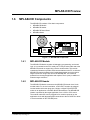
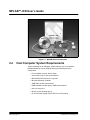
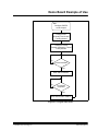
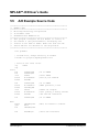
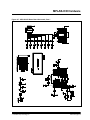
MPLAB™-ICD User’s Guide ADVANCED TRANSDATA CO. 1998 OSC Jumper DIP Switches LEDs POTENTIOMETER Figure 5.1: A/D Example 5.4 A/D Example Main Routine The main routine of demo877.asm (Figure 5.2) begins by configuring PORTC, the A/D module and Timer0. It then waits for a Timer0 overflow to start the A/D conversion of the value from the potentiometer. When the conversion is complete, the value is displayed on the LEDs, and the program loops back to wait for another Timer0 overflow to start another A/D conversion. DS51184A-page 32 1999 Microchip Technology Inc.