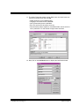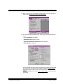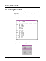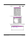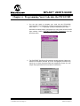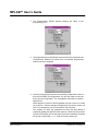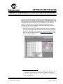
1
P I C S T A R T ®P L US ME C H A T R O N I C S GE T T I N GS T A R T E D GUI D E PICSTART® PLUS MECHATRONICS GETTING STARTED GUIDE Information contained in this publication regarding device applications and the like is intended by way of suggestion only. No representation or warranty is given and no liability is assumed by Microchip Technology Incorporated with respect to the accuracy or use of such information. Use of Microchip’s products as critical components in life support systems is not authorized except with express written approval by Microchip. 1999 Microchip Technology Incorporated. All rights reserved. The Microchip logo, name, PIC, PICmicro, and PICSTART are registered trademarks of Microchip Technology Incorporated in the U.S.A. and other countries. IBM and PC/AT are registered trademarks of International Business Machines Corporation. Windows and MS-DOS are registered trademarks of Microsoft Corporation. All product/company trademarks mentioned herein are the property of their respective companies. 1999 Microchip Technology Inc. DS00177C PICSTART® Plus Mechatronics Getting Started Guide DS00177C 1999 Microchip Technology Inc. GETTING STARTED GUIDE Table of Contents Chapter 1. Getting Started with the PICSTART® Plus Mechatronics Kit .......................................................................................5 1.1 Introduction .................................................................................. 5 Chapter 2. Installing MPLAB-v4.11 or Later ......................................7 2.1 CD-ROM Installation .................................................................... 7 2.2 Connecting the PICSTART Plus Programmer ........................... 12 Chapter 3. Your First Project for Version 4.11 or Later .................15 3.1 Entering Source Code ................................................................ 22 3.2 Building the Project Code .......................................................... 23 Chapter 4. About the Demonstration Program ...............................25 4.1 Instruction Definition .................................................................. 26 4.2 Flowchart of the Program Code ................................................. 28 Chapter 5. Demonstrating the Simulator .........................................29 5.1 Asynchronous Stimulus ............................................................. 29 5.2 Sleep Mode ................................................................................ 37 5.3 Animate ...................................................................................... 37 5.4 Watch Windows ......................................................................... 38 5.5 Break Points ............................................................................... 40 Chapter 6. Programming Your Code into the PIC12C509 ..............41 Appendix A. Programming a PIC12C509 MCU with the 8-pin Pong Game ...............................................45 Appendix B. How to Get Help and Recommended Reading ..............49 Appendix C. Correcting PICSTART® Plus Communications Problems.............................................53 Appendix D. Glossary ............................................................................55 1999 Microchip Technology Inc. DS00177C-page iii Getting Started Guide DS00177C-page iv 1999 Microchip Technology Inc. GETTING STARTED GUIDE Chapter 1. Getting Started with the PICSTART® Plus Mechatronics Kit 1.0 Introduction Microchip strives to give engineers new tools and choices for implementing state-of-the-art control designs.Our minimal footprint microcontrollers are a case in point. There is a great deal of smarts packed into a tiny space in our 8bit microcontrollers. As your designs grow in complexity, the code you write (later) can be easily transitioned to larger Microchip microcontrollers with more peripheral resources. In order to help you get acquainted with the benefits gained by incorporating a microcontroller into your design, we will guide you through the steps in setting up your system, writing a short program, and programming your first PICmicro® MCU. To get started, you need to install Microchip’s MPLAB™ Integrated Development Environment (IDE). PICSTART® Plus Mechatronics Kit, and MPLAB IDE, which is supplied on CD-ROM. 1999 Microchip Technology Inc. DS00177C-page 5 Getting Started Guide NOTES: DS00177C-page 6 1999 Microchip Technology Inc. GETTING STARTED GUIDE Chapter 2. Installing MPLAB-v4.11 or Later 2.1 CD-ROM Installation 1. Insert the MPLAB CD-ROM into your CD-ROM drive. If running Windows®95 with autoplay turned on, MPLAB™ should begin loading. If running Windows95 with autoplay turned off click the START button in the lower left-hand corner of your computer screen. If running Windows 3.1x, select File from the tool bar. 2. Select Run… from the menu to bring up the dialog box. Enter the drive letter for your CD-ROM (i.e., e:) Click OK. Click the Browse button. To begin the installation program, double-click on Mp41100. Note: Future versions of MPLAB will have higher revisions numbers (for example: Mp50000) and are available from Microchip’s web site at www.microchip.com under “Development Tools.” 1999 Microchip Technology Inc. DS00177C-page 7 Getting Started Guide 3. The Select Components window enables you to select which components you want to install. A checkmark in the box will install the component. For this application using the PICSTART® Plus programmer, select the components as shown in the diagram. Click Next to proceed or Back to edit the previous selections. Note: If you have a PICMASTER® emulator or a PRO MATE® programmer, you will want to select the components for them as well. 4. The Select Language Components window enables you to select the Language Components for developing applications in MPLAB. For our purposes the default setting of all selected components is desired. Click Next to proceed or Back to edit the previous selections. DS00177C-page 8 1999 Microchip Technology Inc. 5. Next, select the destination directory where you want to install the MPLAB IDE files. The default setting is C:\Program Files\ MPLAB. Click Next to proceed or Back to edit the previous selections. 6. You can instruct the installation to save any files replaced by the installation process. Use this option if you want to create backups of the originals. The default setting is No. Click Next to proceed or Back to edit the previous selections. 1999 Microchip Technology Inc. DS00177C-page 9 Getting Started Guide 7. This window instructs the installation to add MPLAB to the Start Menu. The default setting is Yes. Click Next to proceed or Back to edit the previous selections. 8. You are ready to start the installation process, click Next to proceed or Back to edit the previous selections. DS00177C-page 10 1999 Microchip Technology Inc. 9. Several Read Me files will be shown sequentially to give you the latest information about the development tools. You may want to read through these prior to clicking OK to proceed. They will look like this: 10. The installation is now complete. Click on Finish. 1999 Microchip Technology Inc. DS00177C-page 11 Getting Started Guide 2.2 Connecting the PICSTART Plus Programmer Turn off your computer. Connect the serial cable and PICSTART Plus Development Programmer to an available COM Port on the back of your computer. Connect the power supply to the PICSTART Plus and plug it in. The power light should be illuminated on the PICSTART Plus. Turn on the computer. 1. Start MPLAB by clicking on the MPLAB icon in the Microchip MPLAB program group. The MPLAB IDE is now running and you are ready to create a project. 2. Since we will be using the PIC12C509 in our design, let’s set up the development mode. From the pull-down menu, select Options>Development Mode. DS00177C-page 12 1999 Microchip Technology Inc. 3. Select MPLAB-SIM Simulator by highlighting the diamond shaped box, then click on the drop-down arrow and choose PIC12C509 as the processor. Then click the Reset button at the bottom of the screen. 4. Next you will set up the PICSTART Plus programmer. From the pull-down menu, select Options>ProgrammerOptions>Select Programmer> PICSTART Plus. 5. Now setup the COM port. From the pull-down menu, select Options>Programmer Options>Communications Port Setup. Select the COM port you have connected to the PICSTART programmer. Note: If you experience any problems with communications, please see Appendix C. 1999 Microchip Technology Inc. PICSTART Plus DS00177C-page 13 Getting Started Guide NOTES: DS00177C-page 14 1999 Microchip Technology Inc. GETTING STARTED GUIDE Chapter 3. Your First Project for Version 4.11 or Later To begin the process of developing your application, you must first create a project. Projects keep track of the windows you have open and the files associated with your design. This enables you to pick up where you left off each time you begin working. 1. Using Windows Explorer, create a project directory for this tutorial called “MECHA” under the MPLAB directory 2. Select Project>New Project… from the pull-down menu. 3. A New Project window appears. Type power1.pjt as your project name and click OK. Select “mecha” under the MPLAB directory, and click OK. 4. The Edit Project window appears, click OK 1999 Microchip Technology Inc. DS00177C-page 15 Getting Started Guide 5. Next, select File>New from the pull-down menu. 6. A new blank source page will open. The default file name will be similar to Untitled1. DS00177C-page 16 1999 Microchip Technology Inc. 7. Again, select File>Save As from the pull-down menu. 8. The Save File As window appears. Make sure your are saving this file into your project directory. Type in power1.asm as the File Name and click OK. 1999 Microchip Technology Inc. DS00177C-page 17 Getting Started Guide 9. Next, you will add the source file to your project. Select Project>Edit Project from the pull-down menu. 10. Click on the project filename power1.hex and press the Node Properties button. DS00177C-page 18 1999 Microchip Technology Inc. 11. The Node Properties window opens. Make sure the check boxes are selected as shown below and click OK. • NODE should be set to POWER1.HEX • Language Tool should be set to MPASM • Hex Format should be set to INHX8M • Error File and List File should be set to On • Case sensitivity, Macro expansion, and Default radix can be set to the user’s preference. For this tutorial configure them as shown. 12. Next, click on the Add Node button to display the Add Node window. 1999 Microchip Technology Inc. DS00177C-page 19 Getting Started Guide 13. Select your source file or type power1.asm as the File Name, and then click OK. 14. You should now see that both nodes are shown in the Project window, as shown below. Click the OK button to save your changes. DS00177C-page 20 1999 Microchip Technology Inc. 15. Now we will set up the Hardware configurations. From the pull-down menu, select Options>Processor Setup>Hardware. 16. The Processor Setup window opens. make sure to select options shown below. • Select Oscillator: Internal RC. • WatchDog Timer should be none. • Stack Overflow Break Enabled should be selected. • MCLR Enable is disabled. Your project has now been created. If at any time you wish to stop working on your project, you can close all windows by selecting Project>Close Project and answer YES to save it. The next time you are ready to continue working, you can select Project>Open Project and pick up where you left off. 1999 Microchip Technology Inc. DS00177C-page 21 Getting Started Guide 3.1 Entering Source Code You are now ready to edit the file power1.asm to create the code needed for your application. (See Chapter 4 for a detailed line-by-line explanation of the source code.) 1. Type the following lines of text in the power1.asm window: Note: This code is case sensitive, pay special attention to lower and upper case characters. In line 3, the text: __CONFIG has 2 underscore characters in it. 2. After entering the source code, select Project>Save Project from the pull-down menu to save your project. DS00177C-page 22 1999 Microchip Technology Inc. 3.2 Building the Project Code 1. You are now ready to build the project. This will produce the hex file that will be used to program the PIC12C509 microcontroller part. A hex file is created from the source file you have written and has the same name as the source file except for the file extension which ends in .hex. The hex file contains the program as it would be written to the PICmicro MCU, in a numeric format. Select Project>Build All from the pull-down menu. 2. If everything has been performed correctly, a Build Results window appears indicating “Build Completed Successfully.” Click close to continue. The close button is the “X” box in the upper right had corner of the window. Note: If the Build Results window indicates errors, recheck your source code in the source file. 3. Click OK to continue. 1999 Microchip Technology Inc. DS00177C-page 23 Getting Started Guide NOTES: DS00177C-page 24 1999 Microchip Technology Inc. GETTING STARTED GUIDE Chapter 4. About the Demonstration Program The program was designed to work with the “Pong Board.” The schematic is located in Appendix A.2. There are two LEDs and two switches. Pressing a switch (left or right) lights the corresponding left or right LED. To better understand the source code program and how it works, below is a line-by-line evaluation of the program. The first three lines of the program (list, #include and __config) and the last line (end) are directives. That is, they are instructions to the assembler about how to create this program, but do not actually translate to program instructions. list p=12c509 This tells the assembler that this program is for the processor PIC12C509. #include <p12c509.inc.> The #include directive tells the assembler to bring in another file at this point. The file named p12c509.inc is provided by Microchip to simplify the naming and assigning of special function registers, flag bits, and configuration word bits. __CONFIG _CP_OFF & _WDT_OFF & _MCLRE_OFF & _IntRC_OSC The __CONFIG directive tells the assembler how you want the configuration word programmed. (See the PIC12C5XX datasheet (DS40139) for details on the configuration word.) All Microchip PICmicro MCUs have a configuration word where certain features of the part are enabled or disabled. (there are two “underscore” characters preceding the word CONFIG, all other occurrences are single underscores) By ANDing the options you have chosen together (with the & character) you construct the desired configuration word. In this case, we have chosen to turn code protect off, the Watchdog Timer off, External Master Clear Pin off, and set the oscillator to internal RC. end The end statement tells the assembler that it has reached the end of the assembly file. All program code is placed before the end statement. count EQU 0x08 The equ directive, called “equate” assigns a value to a label. Here, we are saying that we would like the number 8 to be used in place of the label count in our program. The label count is used as a variable in our example, and is located at address 0x08 in data memory. Note that count is a label, and as such should be placed at the left-most column of the page. 1999 Microchip Technology Inc. DS00177C-page 25 Getting Started Guide 4.1 Instruction Definition To help you better understand the program, we have defined the instructions used in it below. A program flow chart describing the program execution is located on page 28. A more thorough explanation of these instructions, and the many features of this part, can be found in the PIC12C5XX datasheet (DS40139). Note: Many PICmicro instructions can access two registers at the same time. One register is W, the working register, the other register is the data address of your choice. movwf GPIO MOVe W to F. Copies the value currently stored in the W register to the register selected – in this example, the GPIO (General Purpose Input/Output) register. movlw 0x0F MOVe Literal to W. Moves a value into W. In this case, the hexadecimal value F is copied. OPTION Copies the current value of W into the OPTION register. For instance, “wake up on port change” and “weak pullups” are enabled in the option register for this part. (Port pullups cause the inputs to default to one if no other input is present on the pin). TRIS GPIO Copies the current value in W to the direction register (or TRIS register) of the port signified. In this case the port GPIO is being configured. A '1' configures a pin to an input for reading values in, and a '0' configures a pin as an output for writing values out. decfsz count,f DECrement F Skip if Zero. The decfsz instruction decrements the value in the register designated (in this case count). If the result is zero, the instruction immediately following this instruction is skipped (usually a goto instruction which branches back up and causes the value to be continuously decremented until it reaches zero). The result of the decrement can be placed back into the file register designated by ending the instruction with f (as is done here) or it can be copied into the W register by putting a w at the end of the instruction instead of f. Note that if neither f nor w is written, the assembler defaults to f. goto main This instruction causes the program to branch to the location indicated. You will notice that in this example program several 'labels' have been placed in the left column, such as main. Labels make it easier to read a program and DS00177C-page 26 1999 Microchip Technology Inc. see where it is branching. You should note that ONLY labels are placed in the left-most column. Anything else placed to the left edge will be mistakenly interpreted as a label, which could cause errors in your program. clrf STATUS clrf GPIO CLeaR F. The clrf instruction simply clears, or zeros, the contents of the designated register. Here, the STATUS register is being initialized to zero. In this case, the register GPIO is cleared, which has the effect of making all I/O pins configured as outputs, to output a zero. See the PIC12C5XX datasheet (DS40139) for details on the STATUS register. btfsc GPIO,3 Bit Test F, Skip if Cleared. This instruction tests a bit and skips the next instruction if the bit is zero. In this case we are testing bit 3 (which corresponds to pin 4) of the GPIO port to see if a switch has been pressed. The instruction immediately after the bit test is usually a GOTO that branches to another part of the program. sleep The sleep instruction causes the clock oscillator to stop and all program execution to be halted. This puts the part into a low power mode. Several features can be enabled which will wake the processor from sleep. These include, a timed wake-up period, called the WDT, or WatchDog Timer; a reset, caused by a low input on the MCLR pin, if MCLRE is enabled; and finally a change on a port pin (like a key press) if wake-up on pin change is enabled. In this example only wake-up on pin change is enabled. bcf GPIO,0 bsf GPIO,4 These instructions clear a bit (bcf) or set a bit (bsf). Clearing a bit on an output pin causes the output on the pin to go low, or 0V. Setting a bit causes it to go high, or to 5V in a 5V system. In our example, setting a bit turns on an LED connected to the associated pin. In this example, we are clearing bit 0 and setting bit 4 of the GPIO. 1999 Microchip Technology Inc. DS00177C-page 27 Getting Started Guide 4.2 Flowchart of the Program Code START reset movwf clrf OSCCAL STATUS movlw 0x0F OPTION movlw TRIS main keytst 0x08 GPIO Copy Factory Calibration Value to Internal Clock Oscillator and Initialize Status Enable Wake up On Pin Change and Internal Pull-ups Make All Input/Output (I/O) Pins Output Except GPIO3 (an input) decfsz count,f goto main Delay for 256 Loops with 8-bit Count Down from Zero Around to Zero Again clrf GPIO Set All Outputs to Zero (and Thus, Turn Off All LEDs) btfsc SLEEP GPIO,3 GPIO3 = 0? (Is a Switch Pressed?) No Go into low power SLEEP mode. Wake up on button press and reset to START. Yes bsf GPIO,0 btfsc goto GPIO,3 rht_key Set Left Switch = 1 (Left LED is On) Right Switch = 0 Input = 0 or 1? (Left/Right Pressed?) Input = 0 lft_key bcf bsf goto GPIO,0 GPIO,4 main rht_key got main DS00177C-page 28 Note that setting the left switch to 1 also lights the left LED temporarily. Right Switch Pressed, Light Right LED Turn Off Left LED Input = 1 Left Switch Pressed, Left LED Stays On Note that if the right LED is lit, the left LED is now turned off. It will not have been on long enough to be visible. This is an example of how one pin can serve two functions if the part is fast enough. 1999 Microchip Technology Inc. GETTING STARTED GUIDE Chapter 5. Demonstrating the Simulator 5.1 Asynchronous Stimulus The simulator is designed to step through your code to view registers, stimulate pins, etc., for debugging code. Asynchronous Stimulus controls the pin state to either be a high (1) or low (0). 1. To demonstrate this, you must first modify your code. Add a semicolon (;) to line 17 as shown. The semicolon comments out the goto main statement, which allows skipping the delay loop. We are going to step through the code manually for demonstration purposes and do not wish to waste time stepping through 256 cycles of delay loop. Note: 1999 Microchip Technology Inc. After this demonstration, remove the semicolon and reassemble the file or the proper delay will not occur for a programmed part. DS00177C-page 29 Getting Started Guide 2. Next, from the pull-down menu, select Project>Build All. 3. If everything has been performed correctly, a Build Results window will appear indicating “Build Completed Successfully.” Click close to continue. The close button is the ‘X’ box in the upper right hand corner of the window. Note: DS00177C-page 30 If the Build Results window indicates errors, recheck your typing of the source code in the source file or, double-click on the error, and the cursor will be placed inside the source file near the location of the error. 1999 Microchip Technology Inc. 4. Next, from the pull-down menu, select Window>Special Function Registers. The Special Function Register window will now open. This window allows us to see the “GPIO” port. 5. Select Debug>Simulator Stimulus>Asynchronous Stimulus to open the Asynchronous Stimulus window. This window enables you to assign a pin to a button. 1999 Microchip Technology Inc. DS00177C-page 31 Getting Started Guide 6. Move both of the Special Function Registers and Asynchronous Stimulus Dialog windows to allow you to view these along with your source file. MPLAB™ should look like the figure shown. 7. Next, move the mouse cursor to the Asynchronous Stimulus Dialog window. Right-mouse-click on the Stim 1 (P) button and select ‘Assign Pin’. DS00177C-page 32 1999 Microchip Technology Inc. 8. The Pin Section window will appear, double-left-lick on GP3. You have just assigned a pin to the button. 9. Now we want to assign an action to the botton. Move the mouse cursor over to the Asynchronous Stimulus Dialog window. Right-mouse-click on the GP3 (P) button and select ‘Toggle’. 1999 Microchip Technology Inc. DS00177C-page 33 Getting Started Guide 10. Next, we will start stepping through your code. If you feel you need to start over at any time, press the F6 (Reset) key on your keyboard. Press F6 (Reset) now or by Debug>Run>Reset. You will notice the Special Function Register window has changed. The W register is highlighted in red indicating that the register has just been written to. Also in your “source file” a line is highlighted indicating that this is your next instruction to be operated. The highlighted text should be reset movwf OSCCAL as shown in the figure below. DS00177C-page 34 1999 Microchip Technology Inc. 11. Take a look at the Special Function Register window, register gpio. You will notice under the Binary column, there are a series of 1’s and 0’s, like this: 00001000 The first number 0 on the right is GP0. The second number 0 from the right is GP1, and so on. You will notice GP3 is a number 1. This indicates that your Asynchronous Stimulus button is toggled high. If it is low (0), then pressing the button you assigned to this pin will toggle it high (1), after the next instruction is executed. Now press the GP3 button to toggle the pin to low. Click back on your Source Code window then press F7 (Step) or Debug>Run>Step. Take a look at your Special Function Register window. GP3 has changed from a 1 to a 0. Note: 1999 Microchip Technology Inc. To advance the Source Code and Special Function Register window, click on your source code window first, before pressing F7 (Step). DS00177C-page 35 Getting Started Guide 12. Next, step through your code by pressing F7 (Step) until you reach keytst. In your Special Function Register window, check your GPIO register. If GP3 is 1, it will step to the next line sleep. If GP3 is 0, it will skip sleep and go to bsf and keep running code. 13. Now, press the GP3 button. GP3 again will change from a low (0) to a high (1). Note: To advance the Source Code and Special Function Register windows, click on your source code window first, before pressing F7 (Step). Now advance the code 10 times by pressing F7 (Step) ten times while viewing the Source Code. Notice how the code stops advancing, and the highlighted line stays at bsf. You are in sleep mode. See “Sleep Mode” and “Animate” on page 37 for more information. Notice in the schematic, provided in Appendix A, that two different switches are being read by one pin. The simulator only simulates the function of one switch here. DS00177C-page 36 1999 Microchip Technology Inc. 5.2 Sleep Mode Sleep Mode is a power-down mode for conserving battery life. In this program, sleep mode will only happen when GP3 is a 1 or when neither switch is pressed. When sleep mode occurs, it will stop running code and keep incrementing T0PRE. You can press F7 (Step) indefinitely and there will not be any change except to T0PRE. To wake it from sleep, you have to toggle GP3 from a high (1) to a low (0). Once you do that, the code will return to the reset routine, and continue to run code as normal. 5.3 Animate Another useful feature of the MPLAB Simulator is Animate. It allows the simulator to step through the code automatically without user interaction. You can view movement in code, changes in registers, etc. 1. From the pull-down menu, select Debug>Run>Animate. The code will start animating or stepping through the code automatically. Press F5 (Halt) to end Animate. 1999 Microchip Technology Inc. DS00177C-page 37 Getting Started Guide 5.4 Watch Windows Watch Windows are used to view registers that are declared at the beginning of the program, that are not already listed in the Special Function Register window. You may have noticed that there is one in the power1.asm code you wrote called “count.” 1. To create a Watch Window for “count,” select Window>New Watch Window. 2. The Add Watch Symbol window will appear. Type in or select “count,” and then click on Properties button. DS00177C-page 38 1999 Microchip Technology Inc. 3. The Properties window will appear. Select Binary under Format, then click OK. 4. In the Add Watch Symbol window click on Add then Close. 5. Your watch window should look like the figure below. Now stepping through your code using F7 (Step) will allow you to view that particular register without guessing what value is in it. 1999 Microchip Technology Inc. DS00177C-page 39 Getting Started Guide 5.5 Break Points Break points allows the program to stop in “Run” or “Animate” mode at a specified location in your source code for debugging. 1. To demonstrate, move your mouse cursor over to OPTION (line 12 in the source code). Right-mouse-click, and select Break Point(s). 2. Next, press F6 (Reset), and then press F9 (Run). The code will run and stop at line 12 where option is. Now you can view your registers at that moment of the program. Other important areas not covered here include “Trace,” “Arm Counter,” “Stimulus from a File,” and “Environment Setup.” These items are explained in the MPLAB Users Guide, the MPLAB Help Files or you can go to the web site www.microchip.com. DS00177C-page 40 1999 Microchip Technology Inc. MPLAB™ USER’S GUIDE Chapter 6. Programming Your Code into the PIC12C509 1. You are now ready to program your code into the PIC12C509 microcontroller. First, make sure you have removed the semicolon (;) in front of the goto main statement, and then reassemble your code. Otherwise, this delay will be “commented out” and you will not see the LED light correctly. Select PICSTART Plus>Enable Programmer from the pull-down menu. 2. The PICSTART Plus Device Programmer window appears. Make sure that the PIC12C509 is selected. (If it is not, changing the processor may require you to close the project while the programmer resets. You can reopen the project after the correct device is selected.) 1999 Microchip Technology Inc. DS00177C-page 41 MPLAB™ User’s Guide 3. Select Window>Program Memory Window from the pull-down menu to bring the Program Memory Window to the front of your desktop. If the window is not open, select Program>Memory. Your screen should look like this: 4. The Program Memory Window shows the actual opcodes and where they will go in the microcontroller’s program code space. You can change the display format by clicking on the “Document” icon in the upper lefthand corner of the program memory window and selecting Hex Code, Machine Code or Disassembly Display. DS00177C-page 42 1999 Microchip Technology Inc. 5. You are now ready to program the PIC12C509 microcontroller. At this time, you should familiarize yourself with the correct orientation of the PIC12C509 part with respect to Pin 1 and the Zero Insertion Force (ZIF) socket on the PICSTART Plus Programmer. The chip has a notch at one end – designating pin one. Once you have determined the correct orientation of the microcontroller, move the ZIF lever on the PICSTART Plus until the contacts open fully. The chip should be placed into the programmer ZIF socket at the top, with the notch oriented up. Carefully place the PIC12C509 part into the programming socket of the PICSTART Plus Programmer. Once the part is seated, move the lever to the closed position. This will firmly clamp the microcontroller pins and allow the part to be programmed. PICSTART® Plus DEVELOPMENT PROGRAMMER Be sure pin 1 on the chip is oriented to pin 1 of the socket. POWER ACTIVE Insert 8-pin PIC12C509 chip at the top of ZIF socket. 1 8P 18P 28P 40P 6. To program the part, click on the Program button at the bottom of the PICSTART Plus Device Programmer window. 1999 Microchip Technology Inc. DS00177C-page 43 MPLAB™ User’s Guide 7. The Program/Verify window appears showing the status of the programming cycle. 8. The programming cycle should take a few seconds. After completion, the Program/Verify window will indicate that a successful programming session has been completed. 9. Once the microcontroller has been successfully programmed, remove it from the PICSTART Plus Programmer. You are now ready to insert the device into the “Pong Board.” The “Pong Board” schematic is located in Appendix A.2. Notice that the IC socket on the Pong Board also has a notch in it to help you locate Pin 1. When inserting the programmed chip into the socket, use care not to damage the pins as you push the chip into place. The program you have just completed will cause the Pong Board to respond by lighting the right LED if the right key or both keys are pressed. The left LED will light up if the left button is pressed. Otherwise, the board will go into a lower power SLEEP mode to conserve battery life. DS00177C-page 44 1999 Microchip Technology Inc. GETTING STARTED GUIDE Appendix A. Programming a PIC12C509 MCU with the 8-pin Pong Game You have successfully completed this tutorial, and would now like to do more with the Pong board1 provided. A programming file, called 8pinpong.hex2 has been provided on the floppy disk accompanying this tutorial. With this file, you can program another PIC12C509, put it in the board, and play the Pong game. It is assumed that you have successfully completed the tutorial provided. We will therefore provide an abbreviated explanation on how to program the part for the Pong game. 1. Close the open project if you have not already done so. No project is necessary for programming a part when the hex file is already provided. Enable the PICSTART Plus programmer, and select the PIC12C509. Open the Program Memory window (Window>Program Memory). Your screen should look like this: 1. If you are using this tutorial separately from the kit that the Pong board is included in, you can create your own using the schematic in Section A.2. 2. The 8-pin Pong .hex file is also available for download from www.microchip.com. 1999 Microchip Technology Inc. DS00177C-page 45 Getting Started Guide 2. To change the display mode of the Program Memory window, click on its upper left corner (at the document icon) and select Hex Code, Machine Code, or Disassembly Display. We have selected Disassembly Display here. 3. To load the programming file into memory, select File>Import>Download to Memory, as shown below. Locate the file 8pinpong.hex from the floppy disk provided (or on your hard drive if you have copied it over) and select OK. You should see the program memory window change to reflect the loaded program. 4. Make sure that the Configuration Word options (refer to “About the Demonstration Program” section for more details) shown in the PICSTART Plus window under Device Specifications are set as shown: 5. Click the Program button. If the programming process was successful, you can now place the programmed part into the Pong Board, and you are ready to play. DS00177C-page 46 1999 Microchip Technology Inc. A.1 HOW TO PLAY THE 8-PIN PONG GAME 8-pin Pong is a one dimensional version of the original video game played on the 8 LEDs across the top of the board. Each player takes a button at each end of the board. The object is to press the button when the “ball” is at the end of the board. Pressing the button when the ball is at the end returns the ball to the other player. Swing too early or too late and the ball is missed. Winner serves; one point per play; the first player to reach 15 points wins. The game begins with one of the right-most LED flashing, awaiting the serve. The ball is served when the corresponding button is pressed. The ball then moves down the board to the other end. The other player must hit the ball when it gets to the last LED in order to return the ball. Play continues until a player misses the ball. A miss occurs when the ball is not in the last LED. When the ball is hit just right, the ball takes off with a high speed return and the game shifts into high gear. The score is displayed in binary format between plays for a second or two. The left player's score is displayed on the left side of the board and right player's score on the right side. The game is to 15 points, and the winning score is flashed on the screen. The game resets when both players press their buttons simultaneously. The Pong game shuts itself off after 30 seconds of inactivity. Wake-up occurs when either button is pressed. 1999 Microchip Technology Inc. DS00177C-page 47 Getting Started Guide A.2 8-PIN PONG BOARD SCHEMATIC +3 J1 BR1216 +3 U1 1 VDD VSS 2 GP5/OSC1/CLKIN GP0 3 GP1 GP4/OCS2 4 GP3/MCLR/VPP GP2/T0CK1 PIC12C5XX D1 D2 R3 100 DS00177C-page 48 R1 Left Paddle 100 S1 R1 Right Paddle 100 S2 D3 D4 R4 100 8 7 6 5 D5 D6 R5 100 D7 D8 R6 100 1999 Microchip Technology Inc. GETTING STARTED GUIDE Appendix B. How to Get Help and Recommended Reading This tutorial is by no means exhaustive. Important subjects not covered here include writing relocatable programs to be assembled to object files, linking object files, device specifications, complete instruction definitions, applications specific information, and much more. If you are interested in continuing your familiarization with Microchip’s products and development tools, there are a number of items available to you for this purpose. You will find the literature listed in this section on the Microchip CD-ROM and on the web site at www.microchip.com. Hard copies of most literature can be obtained from your local Microchip distributor or representative. If you are interested in obtaining pricing, delivery, samples, literature or any other information, please contact the distributor or factory representative nearest you. A complete listing of these sales offices can be found on the CD-ROM, the web site, and in the back of any Microchip product literature. 1999 Microchip Technology Inc. DS00177C-page 49 Getting Started Guide B.1 OTHER USEFUL LITERATURE FROM MICROCHIP Datasheets for all Microchip PICmicro products are available. The datasheets include device specifications, description of device operation, instruction definitions, product ordering guides and more. Product datasheets can be found on the CD-ROM and the web site. The Embedded Control Handbook, Volume I (DS00092) and II (DS00167). These books contain a complete collection of the Application Notes provided by Microchip to help you design your product. There are many introductory as well as advanced topics covered. Program examples are provided. These application notes can also be found on the CD-ROM and the web site. The Mid-Range PICmicro MCU Reference Manual (DS33023). A guide to using the Microchip Mid-Range family and its peripherals. This is an extensive how to guide and a “must have” for anyone developing for the PIC16CXXX MCU family. MPLAB Tutorial MPLAB IDE, Simulator, and Editor User’s Guide (DS51025) MPASM User’s Guide with MPLINK and MPLIB (DS33014) PICSTART Plus User’s Guide (DS51028) There are extensive Help files installed with MPLAB, and found in the MPLAB Program Group in windows. Some of these files are actually complete electronic versions of the User's Guides. Subjects include MPLAB, MPASM, MPLAB-SIM and PICSTART Plus. Device Errata documents are available from the web site under Datasheets. In these documents Microchip provides the latest device errata and workarounds. The latest version of MPLAB and its components can always be found on the Microchip web site at: www.microchip.com. DS00177C-page 50 1999 Microchip Technology Inc. B.1.1 Additional Resources - Beginning Level Easy PIC’n (English) David Benson/Square 1 Electronics Phone: 707-279-8881 (US) ISBN: 0-9654162-0-8 A Beginners Guide to the Microchip PIC (English) Nigel Gardner/ Bluebird Technical Press Ltd. Phone: 800 718 1997 (US), +44 1536 201 201 (UK) ISBN: 1-899013-01-6, Stock No: 07WX4611 PIC Cookbook Volume 1 (English) Nigel Gardner/Peter Birnie/Bluebird Technical Press Ltd. Phone: 800 718 1997 (US), +113 2636311 (UK) ISBN: 1-899013-02-4, Stock No: 07WX4610 PIC Cookbook Volume 2 (English) Nigel Gardner/Peter Birnie/Bluebird Technical Press Ltd. Phone: 800 718 1997 (US), +113 2636311 (UK) ISBN: 1-901631-00-1, Stock No: 46WX3136 The Greatest Little PIC Book (English) Gordon Mcnee/Bluebird Technical Press Ltd. Phone: 800 718 1997 (US), +113 2636311 (UK) ISBN: 1-901631-01-X Getting Started with PIC Microcontrollers (English) Al Stevens/Ziggurat Technologies Phone: ++ 27 11 7922187 (South Africa) [email protected] PIC16C5X Introductory Course (English) Farsoft Computers cc Phone: ++ 27 11 8289255 (South Africa) [email protected] 1999 Microchip Technology Inc. DS00177C-page 51 Getting Started Guide B.1.2 Additional Resources - Intermediate Level Programming and Customizing the PIC Microcontroller (English) Myke Predko/McGraw-Hill ISBN: 0-07-913646-X PIC’n Up The Pace (English) David Benson/Square 1 Electronics Phone: 707-279-8881 (US) ISBN: 0-9654162-1-6 PIC’s in Practice (English) Francesco Volpe/Safinaz Volpe/Elektor Electronics ISBN: 0-905705-51-3 Les Microcontrolleurs PIC et mise en oeuvre (French) Christian Tavernier/Dunod Fax: +33 1 46 347 846 (France) ISBN: 2-10-002647-X Micontrolleurs PIC a structure RISC (French) C.F. Urbain/Publitronic Fax: +33 1 20 486 964 (France) ISBN: 2-86661-058-X Pratique des Microcontroleurs PIC (French) Francesco Volpe/Safinaz Volpe/Publitronic Elektor ISBN: 2-86661-077-6 Mit dem PIC-Controller Erfolgreich Arbeiten (German) Dr Anne Koenig/Manfred Koenig/Markt & Technik Verlag Phone: 89 460 030 (Germany) ISBN: 3-8272-5168-0 Mikrokontroller mit RISC Struktur (German) C.F Urbain/ Elektor Compact ISBN: 3-928051-83-0 PIC uC Praxis (German) Francesco Volpe/Safinaz Volpe/Elektor Verlag ISBN: 3-89576-030-7 La Programmazione dei Microcontrollori PIC (Italian) Andrea Sbrana Phone: +39 544 464070 (Italy) New Possibilities with the Microchip PIC (Russian) RIGA Phone: +371 935 0550 (Latvia) MicroControladores PIC (Spanish) Christian Tavernier/Paraninfo Phone: 446-3350 (Spain) ISBN: 84-283-2373-9 DS00177C-page 52 1999 Microchip Technology Inc. GETTING STARTED GUIDE Appendix C. Correcting PICSTART® Plus Communications Problems The large majority of the time everything goes well. If you are experiencing any problems getting PICSTART® Plus to communicate, there are a few things you can do. 1. The current version of PICSTART Plus does not work under Windows® NT. NT requires a special hardware driver that is not currently available from Microchip, but is planned for a future release. 2. Make sure that the programmer has power and that the serial cable is connected correctly. 3. Ensure that there are no conflicts with other devices. This often happens when you have a modem or other serial device that is improperly configured. If you believe you are experiencing this problem, consult your Windows manual or other reference literature. You can try removing, reconfiguring or disabling the conflicting device, but do so only if you are familiar with these tasks. 4. Try connecting the PICSTART Plus to a different serial port. If your PC has a 25-pin serial port, you will need a 25- to 9-pin serial port adapter. 5. On some systems errors occur because of driver and hardware incompatibility. Try changing Flow Control to Hardware and/or turning off the FIFO for the serial port. In Windows 95 this is done in the Control Panel. Click the System icon. Next, select the Device Manager tab, and select Ports. (Note, this is also where you would look for conflicts) If necessary, expand the Ports selection by clicking the “+” sign next to it. Now double click on the I/O port that PICSTART Plus is connected to. Select the Port Settings tab. This is where flow control can be set to Hardware. To turn off the FIFO, click the Advanced button. Deselect the Use FIFO box and click OK to save. 6. If you have a COM port but MPLAB will not let you select it (the option is grayed out) you may be able to assign the port manually by editing the mplab.ini file. Typically, this occurs if you have an “opening” in your COM port list. (i.e., you have a COM1, COM2, and a COM4, but no COM3). In this case you may be able to fix it by opening mplab.ini (use the Microsoft® Windows® FIND command to locate this file) and editing the section called [programmers] so that the setting CommPort=1 is set to the port you want selected. This is just a work-around to a deeper problem in which windows is incorrectly reporting port availability through the 16-bit driver. 1999 Microchip Technology Inc. DS00177C-page 53 Getting Started Guide NOTES: DS00177C-page 54 1999 Microchip Technology Inc. GETTING STARTED GUIDE Appendix D. Glossary To provide a common frame of reference, this Glossary defines the terms that follow. Application A set of software and hardware developed by the user, usually designed to be a product controlled by a PICmicro microcontroller (MCU). Assembler Source Code A text file that is processed by an assembler to produce a one-to-one correspondence between assembler instructions and PICmicro machine code. Asynchronous Stimulus Data generated in real-time by the user to simulate external inputs to the simulator. Breakpoint An address where real-time execution of the firmware loaded in program memory will halt. Build A function that recompiles all the source files for an application. C Code A program written in the high level language called “C,” and which will be converted into PICmicro machine code. Caution An alert that is provided to warn you of a situation that would cause physical damage to a device, software file, or equipment. Compile To translate a user’s “C” source text code into machine code. Configuration Bits Unique bits programmed to set modes of operation. A configuration bit may or may not be preprogrammed. Data RAM General purpose file registers from RAM on the PICmicro device being emulated. The File Register window displays data RAM. Dynamic Data Exchange (DDE) 1999 Microchip Technology Inc. DS00177C-page 55 Getting Started Guide The message protocol in Microsoft Windows that transfers information in realtime between windows applications. MPLAB acts as a DDE client that can transmit data to requesting applications, but cannot receive data from other applications. EEPROM Electrically Erasable Programmable Read Only Memory. Emulation The process of executing software loaded in the PICMASTER program memory on the emulator probe as if the firmware resided on the microcontroller device under development. Emulation Memory Program memory contained within the emulator. Emulator Hardware that performs emulation. See Emulation. Emulator System The Microchip Emulator System includes the PICMASTER Pod, the PC Interface Card, a Probe Kit, PRO MATE Device Programmer, Demonstration Board, Socket Module and the MPLAB Software. Export Send data out of MPLAB in a standardized format. Extended Microcontroller Mode (PIC17CXXX Devices Only) In extended microcontroller mode, on-chip program memory as well as external memory is available. Execution automatically switches to external if the program memory address is greater than the internal memory space of the PIC17CXXX device. Inaccessible memory in extended microcontroller mode includes fuses, test memory, and boot memory. External RAM Off-chip Read/Write memory. File Registers On-chip general purpose and special function registers. Halt The command that stops the emulator. Executing Halt is the same as stopping at a breakpoint. The program counter stops, and the user can inspect and change register values, and single step through code. Hex Code A file of executable instructions assembled or compiled from source code into standard hex format code. Hex code can be directly converted to object code. DS00177C-page 56 1999 Microchip Technology Inc. High Level Language A language for writing programs that is of a higher level of abstraction from the processor than assembler code. High level languages employ a compiler to translate statements into machine instructions that the target processor can execute. IDE Integrated Development Environment. An application that has multiple functions for software development. The MPLAB IDE integrates a compiler, an assembler, a project manager, an editor, a debugger, simulator, and an assortment of other tools within one Windows 3.1 application. A user developing an application should be able to write code, compile, debug and test an application without leaving the MPLAB desktop. Import Bring data into the MPLAB Integrated Development Environment (IDE) from an outside source Logic Probes Up to fourteen logic probes connect to the Emulator. The logic probes provide external trace inputs, external trace halt signal, trigger output signal, external break input signal, trace buffer clock, +5V, and a common ground. Make Project A command that rebuilds an application, re-compiling only those source files that have changed since the last complete compilation. Microcontroller Mode One of the possible program memory configurations of the PIC17CXXX family of microcontrollers. In microcontroller mode, only internal execution is allowed. Thus, only the on-chip program memory is available in microcontroller mode. Accessible memory includes: program memory, fuses, test memory and boot memory (FE00h to FFFFh). Microprocessor Mode One of the possible program memory configurations of the PIC17CXXX family of microcontrollers. In microprocessor mode, the on-chip program memory is not used. The entire 64K program memory is mapped externally. Inaccessible memory in microprocessor mode includes fuses, test memory, and boot memory. MPLAB Software The name of the main executable program that supports the IDE with an Editor, Project Manager, and Emulator/Simulator Debugger. The MPLAB Software resides on the PC host. The executable file name is MPLAB.EXE. MPLAB.EXE calls many other files. MRU Most Recently Used. Refers to files and windows available to be selected from MPLAB main pull down menus. 1999 Microchip Technology Inc. DS00177C-page 57 Getting Started Guide Object Code The machine code that is produced from the source code after it is processed by an assembler or compiler. This code will be-the memory-resident code that will run on the PICmicro MCU in the user’s application. Off-Chip Memory Off-chip memory refers to the memory selection option for the PIC17CXXX device where memory may reside on the target board, or where all program memory may be supplied by the Emulator. Options>Processor Setup>Hardware provides the Off-Chip Memory selection dialog box. Pass Counter A counter that decrements each time an event (such as the execution of an instruction at a particular address) occurs. When the pass count value reaches zero, MPLAB halts the processor. You can assign the Pass Counter to either break logic or to trace logic. PC Any IBM or compatible Personal Computer. MPLAB needs a 386 or better machine. PC Host The computer running Windows 3.x. PC Interface Card A Microchip proprietary parallel interface card allowing the MPLAB software residing on the PC to communicate with the PICMASTER emulator. PICMASTER The hardware unit that provides tools for emulating and debugging firmware applications and is also referred to as the Emulator, and PICMASTER. This unit contains Emulation memory, breakpoint logic, counters, timers, and a trace analyzer among some of its tools. PICmicro PICmicro refers to the PIC12CXXX, PIC16CXXX, and PIC17CXXX Microchip microcontroller families. Pod The external emulator box that contains emulation memory, trace memory, event and cycle timers, and trace/breakpoint logic. Occasionally used as an abbreviated name for the PICMASTER Universal In-Circuit Emulator. Power on Reset Emulation A software randomization process that writes random values in data RAM areas to simulate uninitialized values in RAM upon initial power application. DS00177C-page 58 1999 Microchip Technology Inc. Probe A device specific interface between the simulator and the target application. The probe connects to the emulator via a ribbon cable, and the target application board connects to the probe via a ribbon cable. The probe is sometimes called the header board. Program Counter A register that specifies the current execution address. Program Memory Memory in the emulator containing the downloaded target application firmware. Project A set of source files to build the object code for an application. Prototype System A term referring to a user’s target application, or target board. Radix The number base, hex, or decimal, used in selecting an address and for entering data in the Window > Modify command. Run The command that releases the emulator from halt, allowing it to run the application code and change or respond to I/O in real time. SFR Special Function Registers. Simulator A software program that models the operation of the PICmicro microprocessor. Simulator Stimulus Data generated to exercise the response of simulation to external signals. Often the data is put into the form of a list of actions in a text file. Single Step This command steps though code, one instruction at a time. After each instruction, MPLAB updates register windows, watch variables, and status displays so you can analyze and debug instruction execution. You can also single step C compiler source code, but instead of executing single instructions, MPLAB will execute all assembly level instructions generated by the line of the high level C statement. Source Source code, usually a text file of assembly instructions or C code. 1999 Microchip Technology Inc. DS00177C-page 59 Getting Started Guide Special Function Registers Registers that control I/O processor functions, I/O status, timers, or other modes or peripherals. Stack “Push-Down” list of calling routines. Each time a PICmicro microcontroller executes a call, the software pushes the return address to the stack. A RET or RETLW command pops the address from the stack. Static RAM, or SRAM Static Random Access Memory. Program memory you can Read/Write on the target board that does not need refreshing frequently. Step-Into This command is the same as Single Step. Step-Into (as opposed to StepOver) follows a CALL instruction into a subroutine. Step-Over Step-Over allows you to debug code without stepping into subroutines. When stepping over a CALL instruction, the next breakpoint will be set at the instruction after the CALL. If for some reason, the subroutine gets into an endless loop or does not return properly, the next breakpoint will never be reached. The Step-Over command is similar to Single Step except for its handling of CALL instructions. Stopwatch A 48-bit counter for measuring execution cycles. Symbol An label usually produced by an assembler or compiler that refers to machine locations by function names, variable locations, constant declarations, source line-number, or other reference to user source code. System Button The System Button is located in the upper left corner of Windows and some dialogs. This button usually has “Minimize”, “Maximize”, and “Close.” In some MPLAB windows, additional modes or functions can be found under the System Button. Target Refers to a user application. Target Application Firmware residing on the target board. Target Board The circuitry and programmable device that makes up the target application. DS00177C-page 60 1999 Microchip Technology Inc. Target Processor The microcontroller device on the target application board that is being emulated or simulated. Template Lines of text that you build for inserting into your files at a later time. The MPLAB Editor stores templates in template files. Tool Bar A row or column of icons that you can click on to execute MPLAB functions. Trace An emulator or simulator function that logs program execution in real-time. Trigger Output Trigger output refers to an output signal that can be generated at any address or address range, and is independent of the trace, arm, and breakpoint settings. Any number of trigger output points can be set. The trigger output signal is available on logic probe pin 13 (white probe tip). Watchdog Timer A timer on a PICmicro microcontroller that resets the processor after a selectable length of time. Watch Variable A variable that you may monitor during a debugging session. Watch windows contain a list of watch variables that are updated at each breakpoint. 1999 Microchip Technology Inc. DS00177C-page 61 Getting Started Guide NOTES: DS00177C-page 62 1999 Microchip Technology Inc. NOTES: 1999 Microchip Technology Inc. DS00177C-page 63 WORLDWIDE SALES AND SERVICE AMERICAS AMERICAS (continued) Corporate Office Toronto Singapore Microchip Technology Inc. 2355 West Chandler Blvd. Chandler, AZ 85224-6199 Tel: 480-786-7200 Fax: 480-786-7277 Technical Support: 480-786-7627 Web Address: http://www.microchip.com Microchip Technology Inc. 5925 Airport Road, Suite 200 Mississauga, Ontario L4V 1W1, Canada Tel: 905-405-6279 Fax: 905-405-6253 Microchip Technology Singapore Pte Ltd. 200 Middle Road #07-02 Prime Centre Singapore 188980 Tel: 65-334-8870 Fax: 65-334-8850 Atlanta Microchip Asia Pacific Unit 2101, Tower 2 Metroplaza 223 Hing Fong Road Kwai Fong, N.T., Hong Kong Tel: 852-2-401-1200 Fax: 852-2-401-3431 Microchip Technology Inc. 500 Sugar Mill Road, Suite 200B Atlanta, GA 30350 Tel: 770-640-0034 Fax: 770-640-0307 Boston Microchip Technology Inc. 5 Mount Royal Avenue Marlborough, MA 01752 Tel: 508-480-9990 Fax: 508-480-8575 Chicago Microchip Technology Inc. 333 Pierce Road, Suite 180 Itasca, IL 60143 Tel: 630-285-0071 Fax: 630-285-0075 Dallas Microchip Technology Inc. 4570 Westgrove Drive, Suite 160 Addison, TX 75248 Tel: 972-818-7423 Fax: 972-818-2924 Dayton Microchip Technology Inc. Two Prestige Place, Suite 150 Miamisburg, OH 45342 Tel: 937-291-1654 Fax: 937-291-9175 Detroit Microchip Technology Inc. Tri-Atria Office Building 32255 Northwestern Highway, Suite 190 Farmington Hills, MI 48334 Tel: 248-538-2250 Fax: 248-538-2260 Los Angeles Microchip Technology Inc. 18201 Von Karman, Suite 1090 Irvine, CA 92612 Tel: 949-263-1888 Fax: 949-263-1338 New York Microchip Technology Inc. 150 Motor Parkway, Suite 202 Hauppauge, NY 11788 Tel: 631-273-5305 Fax: 631-273-5335 San Jose Microchip Technology Inc. 2107 North First Street, Suite 590 San Jose, CA 95131 Tel: 408-436-7950 Fax: 408-436-7955 ASIA/PACIFIC Hong Kong ASIA/PACIFIC (continued) Taiwan, R.O.C Microchip Technology Taiwan 10F-1C 207 Tung Hua North Road Taipei, Taiwan, ROC Tel: 886-2-2717-7175 Fax: 886-2-2545-0139 EUROPE Beijing United Kingdom Microchip Technology, Beijing Unit 915, 6 Chaoyangmen Bei Dajie Dong Erhuan Road, Dongcheng District New China Hong Kong Manhattan Building Beijing 100027 PRC Tel: 86-10-85282100 Fax: 86-10-85282104 Arizona Microchip Technology Ltd. 505 Eskdale Road Winnersh Triangle Wokingham Berkshire, England RG41 5TU Tel: 44 118 921 5858 Fax: 44-118 921-5835 India Denmark Microchip Technology Inc. India Liaison Office No. 6, Legacy, Convent Road Bangalore 560 025, India Tel: 91-80-229-0061 Fax: 91-80-229-0062 Microchip Technology Denmark ApS Regus Business Centre Lautrup hoj 1-3 Ballerup DK-2750 Denmark Tel: 45 4420 9895 Fax: 45 4420 9910 Japan France Microchip Technology Intl. Inc. Benex S-1 6F 3-18-20, Shinyokohama Kohoku-Ku, Yokohama-shi Kanagawa 222-0033 Japan Tel: 81-45-471- 6166 Fax: 81-45-471-6122 Arizona Microchip Technology SARL Parc d’Activite du Moulin de Massy 43 Rue du Saule Trapu Batiment A - ler Etage 91300 Massy, France Tel: 33-1-69-53-63-20 Fax: 33-1-69-30-90-79 Korea Germany Microchip Technology Korea 168-1, Youngbo Bldg. 3 Floor Samsung-Dong, Kangnam-Ku Seoul, Korea Tel: 82-2-554-7200 Fax: 82-2-558-5934 Arizona Microchip Technology GmbH Gustav-Heinemann-Ring 125 D-81739 München, Germany Tel: 49-89-627-144 0 Fax: 49-89-627-144-44 Shanghai Arizona Microchip Technology SRL Centro Direzionale Colleoni Palazzo Taurus 1 V. Le Colleoni 1 20041 Agrate Brianza Milan, Italy Tel: 39-039-65791-1 Fax: 39-039-6899883 Microchip Technology RM 406 Shanghai Golden Bridge Bldg. 2077 Yan’an Road West, Hong Qiao District Shanghai, PRC 200335 Tel: 86-21-6275-5700 Fax: 86 21-6275-5060 Italy 11/15/99 Microchip received QS-9000 quality system certification for its worldwide headquarters, design and wafer fabrication facilities in Chandler and Tempe, Arizona in July 1999. The Company’s quality system processes and procedures are QS-9000 compliant for its PICmicro® 8-bit MCUs, KEELOQ® code hopping devices, Serial EEPROMs and microperipheral products. In addition, Microchip’s quality system for the design and manufacture of development systems is ISO 9001 certified. All rights reserved. © 1999 Microchip Technology Incorporated. Printed in the USA. 11/99 Printed on recycled paper. Information contained in this publication regarding device applications and the like is intended for suggestion only and may be superseded by updates. No representation or warranty is given and no liability is assumed by Microchip Technology Incorporated with respect to the accuracy or use of such information, or infringement of patents or other intellectual property rights arising from such use or otherwise. Use of Microchip’s products as critical components in life support systems is not authorized except with express written approval by Microchip. No licenses are conveyed, implicitly or otherwise, under any intellectual property rights. The Microchip logo and name are registered trademarks of Microchip Technology Inc. in the U.S.A. and other countries. All rights reserved. All other trademarks mentioned herein are the property of their respective companies. 1999 Microchip Technology Inc. M icrochip Technolog y Inc. 2355 W es t Cha ndler Blvd. Cha ndler, AZ 85224-6199 Tel:480 .786.720 0 Fa x: 480 .899.9210 ©1999 M icrochip Technolog y Inc., Printed inthe U.S.A6/99 DS0 0 177