1
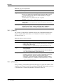
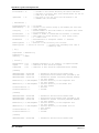
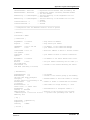
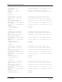
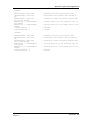
NmxToCD1 Version 1.41 User Guide Nanometrics Inc. Kanata, Ontario Canada © 2001–2005 Nanometrics Inc. All Rights Reserved. NmxToCD1 Version 1.41 User Guide The information in this document has been carefully reviewed and is believed to be reliable for Version 1.41.xx. Nanometrics, Inc. reserves the right to make changes at any time without notice to improve the reliability and function of the product. No part of this publication may be reproduced, stored in a retrieval system or transmitted, in any form or by any means, electronic, mechanical, photocopying, recording, or otherwise, without the prior written permission of Nanometrics Inc. Nanometrics, Inc. 250 Herzberg Road Kanata, Ontario, Canada K2K 2A1 Tel (613)592-6776 Fax (613)592-5929 Email [email protected] Part number DRAFT 14833R3 Release date 2005-04-22 Contents Tables . . . . . . . . . . . . . . . . . . . . . . . . . . . . . . . . . . . . . . . . . . . . . . . . . . . . . . . . . . iii NmxToCD1 . . . . . . . . . . . . . . . . . . . . . . . . . . . . . . . . . . . . . . . . . . . . . . . . . . . . . . 1 1 About NmxToCD1. . . . . . . . . . . . . . . . . . . . . . . . . . . . . . . . . . . . . . . . . . . . . . . . . . . . . . . . 1 1.1 Typical operation . . . . . . . . . . . . . . . . . . . . . . . . . . . . . . . . . . . . . . . . . . . . . . . . . . . . . . . 1 1.1.1 Handling outages. . . . . . . . . . . . . . . . . . . . . . . . . . . . . . . . . . . . . . . . . . . . . . . . . . . . . . 1 1.2 Data compression . . . . . . . . . . . . . . . . . . . . . . . . . . . . . . . . . . . . . . . . . . . . . . . . . . . . . . 2 1.3 Authentication . . . . . . . . . . . . . . . . . . . . . . . . . . . . . . . . . . . . . . . . . . . . . . . . . . . . . . . . . 2 1.4 State of health . . . . . . . . . . . . . . . . . . . . . . . . . . . . . . . . . . . . . . . . . . . . . . . . . . . . . . . . . 2 1.5 Automatic failover to backup system . . . . . . . . . . . . . . . . . . . . . . . . . . . . . . . . . . . . . . . . 3 1.6 Summary of inputs and outputs . . . . . . . . . . . . . . . . . . . . . . . . . . . . . . . . . . . . . . . . . . . . 4 1.6.1 Required input files . . . . . . . . . . . . . . . . . . . . . . . . . . . . . . . . . . . . . . . . . . . . . . . . . . . . 4 1.6.2 Additional inputs . . . . . . . . . . . . . . . . . . . . . . . . . . . . . . . . . . . . . . . . . . . . . . . . . . . . . . 4 1.6.3 Output files . . . . . . . . . . . . . . . . . . . . . . . . . . . . . . . . . . . . . . . . . . . . . . . . . . . . . . . . . . 4 2 Installing NmxToCD1 . . . . . . . . . . . . . . . . . . . . . . . . . . . . . . . . . . . . . . . . . . . . . . . . . . . . . 5 3 Configuring your system for CD-1.0 . . . . . . . . . . . . . . . . . . . . . . . . . . . . . . . . . . . . . . . . . . 5 3.1 Configure the Europa/EuropaT digitisers for authentication . . . . . . . . . . . . . . . . . . . . . . 5 3.2 Configure NaqsServer . . . . . . . . . . . . . . . . . . . . . . . . . . . . . . . . . . . . . . . . . . . . . . . . . . . 6 3.3 Configure NmxToCD1 . . . . . . . . . . . . . . . . . . . . . . . . . . . . . . . . . . . . . . . . . . . . . . . . . . . 6 3.4 Definition of configuration file sections and parameters. . . . . . . . . . . . . . . . . . . . . . . . . . 6 3.4.1 [ NmxToCD1 ] . . . . . . . . . . . . . . . . . . . . . . . . . . . . . . . . . . . . . . . . . . . . . . . . . . . . . . . . 7 3.4.2 [ Connections ]. . . . . . . . . . . . . . . . . . . . . . . . . . . . . . . . . . . . . . . . . . . . . . . . . . . . . . . . 7 3.4.3 [ TxParameters ] . . . . . . . . . . . . . . . . . . . . . . . . . . . . . . . . . . . . . . . . . . . . . . . . . . . . . . 8 3.4.4 [ Log ]. . . . . . . . . . . . . . . . . . . . . . . . . . . . . . . . . . . . . . . . . . . . . . . . . . . . . . . . . . . . . . . 9 3.4.5 [ Station ] . . . . . . . . . . . . . . . . . . . . . . . . . . . . . . . . . . . . . . . . . . . . . . . . . . . . . . . . . . . 10 3.4.6 [ Channel ] . . . . . . . . . . . . . . . . . . . . . . . . . . . . . . . . . . . . . . . . . . . . . . . . . . . . . . . . . . 10 4 Running NmxToCD1. . . . . . . . . . . . . . . . . . . . . . . . . . . . . . . . . . . . . . . . . . . . . . . . . . . . . 11 4.1 Starting and stopping NmxToCD1 manually . . . . . . . . . . . . . . . . . . . . . . . . . . . . . . . . . 11 4.2 Using the NmxToCD1 run-time commands . . . . . . . . . . . . . . . . . . . . . . . . . . . . . . . . . . 12 4.3 Managing NmxToCD1 remotely. . . . . . . . . . . . . . . . . . . . . . . . . . . . . . . . . . . . . . . . . . . 12 4.4 Viewing the TxHistory file. . . . . . . . . . . . . . . . . . . . . . . . . . . . . . . . . . . . . . . . . . . . . . . . 12 4.5 Monitoring NmxToCD1 operation. . . . . . . . . . . . . . . . . . . . . . . . . . . . . . . . . . . . . . . . . . 13 4.5.1 Normal operation . . . . . . . . . . . . . . . . . . . . . . . . . . . . . . . . . . . . . . . . . . . . . . . . . . . . . 13 4.5.1.1 Automatic failover . . . . . . . . . . . . . . . . . . . . . . . . . . . . . . . . . . . . . . . . . . . . . . . . . . . 13 4.5.2 Troubleshooting. . . . . . . . . . . . . . . . . . . . . . . . . . . . . . . . . . . . . . . . . . . . . . . . . . . . . . 14 4.5.2.1 Configuration file error detection. . . . . . . . . . . . . . . . . . . . . . . . . . . . . . . . . . . . . . . . 14 4.5.2.2 Check the connection to NaqsServer . . . . . . . . . . . . . . . . . . . . . . . . . . . . . . . . . . . . 14 4.5.2.3 Check the connection to IDC . . . . . . . . . . . . . . . . . . . . . . . . . . . . . . . . . . . . . . . . . . 14 4.5.2.4 Check that data are getting to Naqs . . . . . . . . . . . . . . . . . . . . . . . . . . . . . . . . . . . . . 15 Appendix A Log File and Configuration File . . . . . . . . . . . . . . . . . . . . . . . . . . . . . . . . . . . . . . 17 A.1 Log file overview . . . . . . . . . . . . . . . . . . . . . . . . . . . . . . . . . . . . . . . . . . . . . . . . . . . . . . . . A.1.1 Error messages . . . . . . . . . . . . . . . . . . . . . . . . . . . . . . . . . . . . . . . . . . . . . . . . . . . . . . . A.2 Configuration file overview . . . . . . . . . . . . . . . . . . . . . . . . . . . . . . . . . . . . . . . . . . . . . . . . A.2.1 Editing the NmxToCD1 configuration file . . . . . . . . . . . . . . . . . . . . . . . . . . . . . . . . . . . . A.2.1.1 Data order and default values . . . . . . . . . . . . . . . . . . . . . . . . . . . . . . . . . . . . . . . . . . . A.2.1.2 White space and comments . . . . . . . . . . . . . . . . . . . . . . . . . . . . . . . . . . . . . . . . . . . . 17 17 18 18 19 19 i Contents A.2.2 Example NmxToCD1.ini file. . . . . . . . . . . . . . . . . . . . . . . . . . . . . . . . . . . . . . . . . . . . . 19 ii Tables 1-1 NmxToCD1 log message types . . . . . . . . . . . . . . . . . . . . . . . . . . . . . . . . . . . . . . . . . . . . . 4 3-1 [ NmxToCD1 ] section parameter. . . . . . . . . . . . . . . . . . . . . . . . . . . . . . . . . . . . . . . . . . . . 7 3-2 [ Connections ] section parameters . . . . . . . . . . . . . . . . . . . . . . . . . . . . . . . . . . . . . . . . . . 7 3-3 [ TxParameters ] section parameters . . . . . . . . . . . . . . . . . . . . . . . . . . . . . . . . . . . . . . . . . 8 3-4 [ Log ] section parameters . . . . . . . . . . . . . . . . . . . . . . . . . . . . . . . . . . . . . . . . . . . . . . . . 10 3-5 [ Station ] section parameters . . . . . . . . . . . . . . . . . . . . . . . . . . . . . . . . . . . . . . . . . . . . . 10 3-6 [ Channel ] section parameters . . . . . . . . . . . . . . . . . . . . . . . . . . . . . . . . . . . . . . . . . . . . 11 4-1 NmxToCD1 command options . . . . . . . . . . . . . . . . . . . . . . . . . . . . . . . . . . . . . . . . . . . . . 12 A-1 Subset of error messages . . . . . . . . . . . . . . . . . . . . . . . . . . . . . . . . . . . . . . . . . . . . . . . . 17 iii Tables iv NmxToCD1 1 About NmxToCD1 NmxToCD1 Version 1.41 forwards time series data from a Nanometrics data acquisition system to an IDC data center, using the CD-1.0 data format and protocol defined in IDC 3.4.2 Rev. 0.1 (February 2002) (http://www.rdss.info/). Each instance of the NmxToCD1 program represents a single IDC “station”, which may include up to 100 data channels from different Nanometrics stations. Data are sent to the IDC as CD-1.0 data frames in near-real time; missing data are handled as described in Section 1.1.1. This manual provides instructions for installing, configuring, and running NmxToCD1, and an overview of the NmxToCD1 log file and configuration file. 1.1 Typical operation NmxToCD1 is designed to accept authenticated data from Nanometrics Europa and EuropaT digitisers. Each digitiser builds and signs CD-1.0 subframes in real time, then forwards the data and signed subframe headers separately to the NaqsServer data acquisition program in a proprietary Nanometrics data format. NaqsServer ensures that each data stream is complete, and maintains a ringbuffer (archive) containing the most recent several days of data for each channel. NmxToCD1 subscribes to real-time data from NaqsServer via TCP socket using the Naqs Datastream interface, and maintains a second TCP connection to the IDC data center. NmxToCD1 assembles time series data and subframe headers for each channel into CD-1.0 frames. Frames have a fixed time duration (typically 10 seconds) and contain data for all channels comprising the IDC station. The data for each channel within a frame is called a channel subframe. During normal operation, CD-1.0 frames are built and sent to the IDC in near-real time as online data are received from Naqs. 1.1.1 Handling outages Occasionally data may be missing or delayed due to telemetry errors. In this case, NmxToCD1 will wait for missing data until a configurable timeout has expired, then send the incomplete frame. The incomplete frame will contain the channels with complete data; channels with missing samples are not sent (these channels will be sent later if the missing data are recovered). DRAFT 14833R3 2005-04-13 NmxToCD1 Version 1.41 User Guide 1 NmxToCD1 If the connection to IDC is lost, or if the bandwidth of the connection is (temporarily) insufficient to handle the required data rate, data frames are buffered, then sent in reverse chronological order when the connection is reestablished. There is also the option to send the data frames in chronological order. For outage recovery, NmxToCD1 maintains a history file (TxHistory.cd1) that records the transmission status of each data frame, keeping track of which channels were sent or not. When the NmxToCD1 program is started, it updates TxHistory.cd1 to include frames which should have been built while it was shut down and marks them as never sent. When NmxToCD1 has established a connection to the IDC receiver, it sends frames with the following priority within the available connection bandwidth: 1. Current data (real-time data) 2. Data that was never sent 3. Completion recovery data The latter two data are sent in the configured chronological order (see Table 3-3, “[ TxParameters ] section parameters,” on page 8). Subframes for channels that were missing or incomplete when the frame was originally sent are rebuilt from data in the Naqs ringbuffers. If one or more of the missed channels are now complete, then a frame is sent containing only those channels which are now complete and were not sent previously. 1.2 Data compression NmxToCD1 supports both of the compression options specified in [IDC 3.4.2]. Data for each channel may be sent in uncompressed format (as 4-byte IEEE integers) or in Canadian compressed format (a second-difference compression format). The compression scheme is set via the NmxToCD1.ini file (Table 3-5, “[ Station ] section parameters,” on page 10). 1.3 Authentication Nanometrics Europa and EuropaT digitisers equipped with the authentication option provide data authentication following the IDC 3.4.2 format. Each channel subframe is signed with a 40-byte signature generated using the DSA signature algorithm. Datasigning capability within the digitiser is provided by an onboard PCMCIA encryption token. This provides complete security, because the private key used to sign the data cannot be exported from the token. NmxToCD1 does not perform any data signing itself, and therefore does not require an encryption token. 1.4 State of health The CD-1.0 format as defined in [IDC 3.4.2] provides a status field within each channel subframe to define the channel status for the current frame. NmxToCD1 supports these defined channel status indicators: Clipped (bit 29) – This bit is set when the signal is clipped. 2 NmxToCD1 Version 1.41 User Guide DRAFT 14833R3 2005-04-13 NmxToCD1 Calibration is in progress (bit 28) – This bit can be mapped to an external SOH channel of the digitiser; it will be set if the scaled SOH value exceeds 1.0 at any time during the frame. The selected SOH channel should be used to monitor the calibration-enable signal on the digitiser, and scaled appropriately (for example, 0 = normal, 5 = calibration enabled). The Trident digitiser does not need a calibration SOH channel to be assigned. Vault door is open (bit 23) – This bit can be mapped to an external SOH channel of the digitiser; it will be set if the scaled SOH value exceeds 1.0 at any time during the frame. The selected SOH channel should be used to monitor the vault door switch or transducer, and scaled appropriately (for example, 0 = closed, 5 = open). Authentication box has been opened (bit 22) – This bit can be mapped to an external SOH channel of the digitiser; it will be set if the scaled SOH value exceeds 1.0 at any time during the frame. The selected SOH channel should be used to monitor the authentication box tamper switch or transducer, and scaled appropriately (for example, 0 = closed, 5 = open). Clock differential is too large (bit 20) – This bit is set if the GPS is unlocked and the estimated maximum clock differential exceeds the configured limit. NmxToCD1 supports these additional status indicators: Supply voltage is out of range (bit 15) – This bit is set if the supply voltage to the digitiser is out of range at any time during the frame. Internal temperature is out of range (bit 14) – This bit is set if the Europa Digitiser internal temperature is out of range at any time during the frame. Signature is incorrect (bit 2) – This bit is set if the signature is known to be incorrect. Signature is unavailable (bit 1) – This bit is set if the signature is unavailable, either because there is no token present or because the subframe header was not received by NmxToCD1. Status is not available (bit 0) – This bit is set if the status information is not available; other status bits should be ignored. This may occur if the subframe header was not received by NmxToCD1. The assignment of some SOH channels to status bit and definition of some SOH thresholds are configured on the Europa digitiser (see Section 3.1 on page 5). ###temperature offset? 1.5 Automatic failover to backup system On startup, each CPCSS CPU is automatically assigned either active or standby mode: The active CPU handles data transfer to the IDC. The standby CPU maintains a hot backup of the transmission state of the active side. The first time that the system is ever started, the active side should be started first. The standby CPU switches to active after a configurable timeout of no activity from the active CPU (see also Table 3-2, “[ Connections ] section parameters,” on page 7).The operating mode (active or standby) is maintained in a file that is created on shutdown, therefore a failed-active CPU will assume standby mode automatically on restart by the DRAFT 14833R3 2005-04-13 NmxToCD1 Version 1.41 User Guide 3 NmxToCD1 absence of the mode file. The current operating mode of a CPU can be observed from its log output, where the standby CPU log contains only one type of operational message (“got state update” messages). 1.6 Summary of inputs and outputs 1.6.1 Required input files NmxToCD1.ini – This configuration file defines operating characteristics for the NmxToCD1 program. Naqs ringbuffers – NmxToCD1 requires read access to the Naqs ringbuffer files for outage recovery. These files must either be stored on the same machine as NmxToCD1 or be accessible over a LAN on a shared drive. 1.6.2 Additional inputs Near-realtime data from NaqsServer – NmxToCD1 receives online data from NaqsServer Datastream service. This requires a TCP connection to Naqs. See also the Nanometrics Data Formats reference guide for information on private data streams, and the NaqsServer user guide. 1.6.3 Output files NmxToCD1_yyyymmdd.log – The log file contains diagnostic messages generated by NmxToCD1. Each log message has an associated type, ranked by severity (Table 1-1). Log verbosity can be configured to show only messages at or above a specified severity level. The verbosity of the log on startup is set in the [ Log ] section of the NmxToCD1.ini file (Section 3.4.4). While NmxToCD1 is running, you can set verbosity to a different level by using the run-time commands (Section 4.2). Table 1-1 NmxToCD1 log message types Label Description F Fatal errors – Serious errors which cause immediate system shutdown. E Errors – Abnormal occurrences which will likely affect data integrity. W Warnings – Less serious abnormal occurrences. I Informational messages – Messages tracing the normal operation of the system. V Verbose messages – Detailed informational messages tracing the normal operation of the system. D Debug messages – Additional verbose trace messages. Caution The output files TxHistory.cd1 and CalHistory.cd1 are used by the system. Do not edit these files. TxHistory.cd1 (transmission history file) – The TxHistory.cd1 file records the transmission status of each frame built by NmxToCD1. This information is used to determine which frames and channels need to be retransmitted to IDC. The file is a ringbuffer which keeps the transmission status for the most 4 NmxToCD1 Version 1.41 User Guide DRAFT 14833R3 2005-04-13 NmxToCD1 recent few days; the duration of the file is set in the NmxToCD1.ini file (Section 3.4.3). To list the contents of the TxHistory.cd1 file, run the program ViewHistory from the command line. See Section 4.4 on page 12; synopsis: viewhistory filename [-b] [-s start time] [-d duration] CalHistory.cd1 (calibration history file) – The CalHistory.cd1 file records the history of accepted calibrations broadcast from the Calibrate software, including updated calib (calibration factor) and calper (calibration period) values. You can view this file in any text editor. 2 Installing NmxToCD1 NmxToCD1 must be installed either on the NaqsServer computer, or on a computer that has TCP/IP access to the Naqs computer and network access to the Naqs ringbuffers. See the installation instructions for the acquisition system workstation. 3 Configuring your system for CD-1.0 To configure your data acquisition system to send authenticated data via CD-1.0, you must correctly configure the digitisers, NaqsServer, and NmxToCD1. This section provides the basic procedures for configuring each of these components. If you need more detailed information, see also the Nanometrics UI and NaqsServer user guides. 3.1 Configure the Europa/EuropaT digitisers for authentication 1. Start the Nanometrics UI and log on to the digitiser with tech access. 2. Click the Configuration tab to open the set of configuration panels. 3. Open the Authentication panel. 4. In the Signing section, enter values for: • the number of channels to sign • the CD1 frame duration • the login password for the token • the CD1 version: choose CD1.0 5. In the Status Monitor section, enter values for: • voltage, temperature, and clock differential thresholds • the SOH channels to monitor calibration, vault door, and authentication box (Systems with Trident digitisers do not need a calibration SOH channel.) In each case, the selected SOH channel should be connected to the appropriate signal or transducer. 6. Open the System panel. In the External SOH Calibration (units/volt) section: a) Enter values to set the SOH offset and calibration factors to scale the SOH values appropriately (see also the Nanometrics UI manual). DRAFT 14833R3 2005-04-13 NmxToCD1 Version 1.41 User Guide 5 NmxToCD1 For example, for a tamper switch, the switch closed condition should read 0V and the switch open condition should read 5V. The status bit will be set if the scaled SOH value exceeds 1.0. b) Edit each channel label as appropriate. 7. Open the Ringbuffers panel. Ensure that there is both a data ringbuffer and an authentication ringbuffer for each channel to be signed. For the authentication ringbuffers, each hour of data requires about 64 kilobytes. 8. Save the configuration: a) Click Submit. b) In the Submitting Config dialog box, click OK. c) When you are satisfied that the configuration is correct, click Commit to save the changes to the digitiser flash memory. 3.2 Configure NaqsServer NaqsServer must be configured to receive and archive both time series data and subframe headers for each authenticated data channel. The subframe headers are treated as generic serial data by NaqsServer. To configure NaqsServer to receive the subframe header channels, add the required entries to the Naqs.stn file: 1. Following the [ ChannelPrototype ] sections, add one or more [ SerialChannelPrototype ] sections defining the data streams containing the subframe headers. In each prototype: a) Set BytesPerPacket to 68. b) Set the Port number to 16, 17, and 18 for data channels 1, 2, and 3 respectively (for example, authentication on data for sensor components Z, N, and E). c) Choose a unique TypeName to identify the resulting streams as subframe headers (for example, AUZ, AUN, and AUE for streams corresponding to the Z, N, and E components). 2. Following each [ Instrument ] section add one [ SerialChannel ] section for each authenticated data channel on this digitiser, to configure Naqs to receive the subframe headers. 3.3 Configure NmxToCD1 Edit the configuration file /nmx/user/NmxToCD1.ini using values that are appropriate for your network. The configuration file is described in Section 3.4, and an example is given in Section A.2 on page 18. 3.4 Definition of configuration file sections and parameters The NmxToCD1.ini file contains these sections: [ NmxToCD1 ] [ Connections ] 6 NmxToCD1 Version 1.41 User Guide DRAFT 14833R3 2005-04-13 NmxToCD1 [ TxParameters ] [ Log ] [ Station ] [ Channel ] All sections are required. There must be exactly one section of each type, except [ Channel ] (there may be 1 to 100 [ Channel ] sections). All sections, and all parameters within sections, must be in the order as listed below. 3.4.1 [ NmxToCD1 ] The [ NmxToCD1 ] section defines the station name (Table 3-1). This must be the first section in the file. Table 3-1 [ NmxToCD1 ] section parameter 3.4.2 Parameter Description StationCode The IDC station name for this installation. [ Connections ] The [ Connections ] section defines the IP address and port for connecting to Naqs, the IDC Connection Manager, and the standby system. It contains the parameters described in Table 3-2. Table 3-2 [ Connections ] section parameters DRAFT 14833R3 2005-04-13 Parameter Description NaqsAddress The IP address or host name of the NaqsServer machine. • Permitted values: a valid host name or dotted decimal IP address. NaqsPort The port number of the Naqs Datastream service. • Permitted values: a valid port number, typically 28000. IdcAddress The IP address or host name of the IDC Connection Manager. • Permitted values: a valid host name or dotted decimal IP address. IdcPort The port number of the IDC Connection Manager well-known port. • Permitted values: a valid port number. CalMcastAddr The multicast address on which to receive calibration updates. • Permitted values: a valid multicast address in dotted decimal format. CalPortNum The port number on which to receive calibration updates. • Permitted values: a valid port number. MateAddress The IP address of the remote active fault-tolerant mate accepting the connection. This is only needed on the connection initiating side. • Permitted values: a valid IP address in dotted decimal format or host name. MatePort The TCP port number connecting the two sides of the failover system. • Permitted values: a valid port number. Use MatePort = 0 to run standalone. NmxToCD1 Version 1.41 User Guide 7 NmxToCD1 Table 3-2 [ Connections ] section parameters (Continued) 3.4.3 Parameter Description ConnAcceptor Indicates whether this computer is the connection acceptor or initiator. • Permitted values: 1 – accept connection, 0 – initiate connection. The parameter value must be different for each side. FailoverTime The amount of time to wait (in seconds) before declaring the remote side dead and doing a failover. • Permitted values: any positive integer, with the recommended minimum value of 60. Select a value that will allow brief temporary events (such as a user-initiated shutdown/restart of the active side) to proceed without causing a failover. To avoid a race condition in case of simultaneous startup of both main and standby systems, set this parameter to a value that is larger by a few seconds for the standby side than it is for the main side. UpdateTime How often (in seconds) to copy the state from the ACTIVE side to the STANDBY side. Select a value that accounts for the speed of the link between the sides. That is, for a slow link use a high enough value to allow an update to complete before starting the next update. • Permitted values: any positive integer. [ TxParameters ] The [ TxParameters ] section defines the CD-1.0 transmission characteristics of the station. It contains the parameters described in Table 3-3. Table 3-3 [ TxParameters ] section parameters 8 Parameter Definition FrameTimeLength The duration of each CD-1.0 data frame, in seconds. Each digitiser must be configured with the same FrameTimeLength to ensure transmission of properly authenticated data. • Permitted values: any integer from 5 to 60. Typical value is 10. • Recommended settings: 10 seconds for short-period or broadband seismic data, and hydroacoustic data; 20 seconds for long-period seismic data and infrasonic data. MaxFrameDelay The maximum time in seconds that a data frame will be delayed waiting for missing data. If this time is exceeded an incomplete data frame will be sent, containing only those channels for which all data have been received. Channels which are not sent will be sent later if the missing data are recovered. • Permitted values: any integer from 30 to 300. Typical value is 180. Contiguity The minimum number of real-time frames of contiguous data useful for automatic processing at IDC. This is the distance between markers in the modified LIFO ordering scheme (see GSE Conference Room Paper/243, dated 20 July 1995). • Permitted values: any integer from 1 to 10. Typical value is 3. RetxOnConnect The number of frames to be retransmitted when the connection to the CD1 receiver is lost, then re-established. This is to ensure delivery of frames which may have been lost at the receiver when the connection was closed. • Permitted values: any integer from 0 to 20. Typical value is 10. NmxToCD1 Version 1.41 User Guide DRAFT 14833R3 2005-04-13 NmxToCD1 Table 3-3 [ TxParameters ] section parameters (Continued) Parameter Definition MostRecentFirst This defines the order in which unsent frames will be sent to IDC after a transmission outage. • Permitted values: 1 – send most recent frames first (LIFO order), 0 – send oldest frames first (FIFO order). RetxEnabled This indicates if incomplete frames should be retransmitted if more data become available (see also MaxFrameDelay, above). • Permitted values: 1 – retransmission of incomplete frames is enabled, 0 – retransmission of incomplete frames is disabled. TxHistoryHours The duration in hours of the TxHistory.cd1 file. Select a value that approximately matches the duration of the acquisition system data ringbuffer. • Permitted values: any positive float number. TxHistoryStart An optional parameter that is used to define the start time of the TxHistory.cd1 file. If TxHistoryStart is not used, the transmission history will be defined to start at the present time if the file does not already exist, and will remain unmodified if the file does exist. • TxHistoryStart can be used to define the period for which unsent data are recovered when NmxToCD1 is started. Typically, this is done in one of two ways: • If TxHistory.cd1 exists when NmxToCD1 is started, all frames with start time earlier than TxHistoryStart will be marked as sent and complete. The transmission history for frames later than TxHistoryStart will not be affected. This allows the system operator to limit the period for which catch-up frames are sent. • If TxHistory.cd1 does not exist when NmxToCD1 is started, then it will be created with a start time of TxHistoryStart, and all frames from TxHistoryStart to the present time will be marked as unsent. This allows the system operator to specify (on startup) a period for which catch-up frames should be sent. If TxHistoryStart is set to be later than the current time or earlier than the start time of an existing TxHistory.cd1 file, it will be ignored. This ensures that the parameter takes effect only the first time that NmxToCD1 is started. Restarting NmxToCD1 with the same value of TxHistoryStart will not cause any further modification of the history file. • Permitted values: a valid date in format yyyy-MM-dd-HH-mm-ss, or the parameter is not used. Example: TxHistoryStart = 2004-04-21-12-00-00 //standard format or TxHistoryStart = 2004/04/21 12:00:00 //alternate format or comment out the line to disable this parameter: //TxHistoryStart = 2004-04-21-12-00-00 //not used 3.4.4 [ Log ] The [ Log ] section defines the name and location of the NmxToCD1 log file and its verbosity setting at startup. It contains the parameters described in Table 3-4. (See also Section A.1, “Log file overview”.) DRAFT 14833R3 2005-04-13 NmxToCD1 Version 1.41 User Guide 9 NmxToCD1 Table 3-4 [ Log ] section parameters 3.4.5 Parameter Description LogFilename The base name for the NmxToCD1 log file. NmxToCD1 creates a new log file every day. The log file name is determined by inserting the date in format yyyymmdd between the base name and the file extension; for example, NmxToCD1_20040419.log. • Permitted values: any valid file name, with no spaces. Example: LogFilename = NmxToCD1.log LogDirectory The directory in which to store the NmxToCD1 log file. • Permitted values: any valid directory name, with no spaces. Do not use a trailing slash. Verbosity The startup verbosity of the NmxToCD1 log file. • Permitted values: FATAL, ERROR, WARNING, INFO, VERBOSE, or DEBUG (see also Table 1-1 on page 4). Typical value is INFO. [ Station ] The [ Station ] section defines parameters such as state-of-health thresholds which apply to the entire IDC station; that is, to all channels. It contains the parameters described in Table 3-5. Table 3-5 [ Station ] section parameters 3.4.6 Parameter Definition MaxSampleRate This is the maximum sample rate for all channels of this station. It is used, together with number of channels and frame time length, to compute the maximum frame size in bytes. • Permitted values: any positive integer. Typical values are 40 or 100. Signed This indicates whether authentication signatures should be sent with each channel subframe. • Permitted values: Yes – send signatures with each channel subframe, No – do not send signatures. Typical value is Yes. Compressed Indicates whether data should be sent in compressed format using the Canadian compression scheme. This reduces bandwidth requirements, so this should be set to Yes if the receiving program supports compression. (Uncompressed data are sent as 4-byte IEEE integers.) • Permitted values: Yes – send data in compressed format, No – send data in uncompressed format. [ Channel ] Each [ Channel ] section defines parameters that apply to a single data channel. There should be one [ Channel ] section for each channel of the IDC station (there can be up to 100 channels). It contains the parameters described in Table 3-6. 10 NmxToCD1 Version 1.41 User Guide DRAFT 14833R3 2005-04-13 NmxToCD1 Table 3-6 [ Channel ] section parameters Parameter Definition NmxChannelName The channel name defined by NaqsServer. This defines the data source for this channel. The channel name must be defined in the NaqsServer Naqs.stn file. • Permitted values: a string in dotted format. Example: NmxChannelName = STN01.BHZ IdcChannelName The registered name for this channel as provided by IDC. Both the NmxChannelName and the IdcChannelName must be unique, to ensure that each Nanometrics channel maps to a single IDC channel. • Permitted values: a string of 1 to 16 characters. HdrChannelName The name of the Naqs serial data channel containing subframe headers for this data channel. This serial data channel must be defined in the Naqs.stn file. The subframe header contains the timestamp, status bits, and signature computed by the digitiser. • Permitted values: a string in dotted format. Example: HdrChannelName = STN01.AUZ RbfDirectory The absolute pathname for the disk directory containing the Naqs ringbuffer for this channel. NmxToCD1 needs read access to the Naqs ringbuffers in order to transmit or retransmit old data. • Permitted values: a valid pathname with no spaces. Do not include a trailing slash. Examples: RbfDirectory = D:\ringbuffers RbfDirectory = /ringbuffers HdrDirectory The absolute pathname for the disk directory containing the Naqs ringbuffer of serial data channel subframe headers. NmxToCD1 needs read access to Naqs ringbuffers in order to transmit or retransmit old data. • Permitted values: a valid pathname with no spaces. Do not include a trailing slash. CalibrationFactor The calibration factor for this channel in nanometres per count. • Permitted values: any positive float number. CalibrationPeriod The period in seconds at which the calibration factor is valid. • Permitted values: any positive float number. 4 Running NmxToCD1 In a typical network, NmxToCD1 will be set up to start automatically using scripts (on Solaris and Linux) or the NmxWatchdog program (on Windows). It can also be started manually from the command line. Once NmxToCD1 is running, you can use the console window options to change the log message verbosity, to create a new log file, to restart NmxToCD1, and to stop NmxToCD1. 4.1 Starting and stopping NmxToCD1 manually Solaris and Linux: To start NmxToCD1, enter NmxToCD1 start in any terminal window. DRAFT 14833R3 2005-04-13 NmxToCD1 Version 1.41 User Guide 11 NmxToCD1 To stop NmxToCD1, enter NmxToCD1 stop in any terminal window. Windows: To start NmxToCD1, enter NmxToCD1 in any command window. To stop NmxToCD1, enter quit in the NmxToCD1 command window. 4.2 Using the NmxToCD1 run-time commands The NmxToCD1 console window displays log messages generated by the NmxToCD1 program (see Section A.1, “Log file overview” for a description of log messages). It also supports a basic keyboard interface, with the options described in Table 4-1. On Solaris and Linux, you can run these commands from any terminal window. Enter NmxToCD1 command On Windows, run these commands from the NmxToCD1 console window. Enter command Table 4-1 NmxToCD1 command options To do this... Enter this command... Generate all log messages to the log file; set the log verbosity to DEBUG D Suppress debug messages in the log file; set the log verbosity to VERBOSE V Suppress debug and verbose messages in the log file; set the log verbosity to INFO I Move the log file (close the current log and start a new file) M Restart NmxToCD1 restart Stop NmxToCD1 and exit Quit 4.3 Managing NmxToCD1 remotely You can enable the CD1 sender via the AutoDRM START_CONTINUOUS command, and disable the CD1 sender via the AutoDRM STOP_CONTINUOUS command. If running in fault-tolerant mode with 2 CPUs, the standby side must be shut down first. This requires AutoDRM to be running on both CPUs. 4.4 Viewing the TxHistory file To list the contents of the transmit history file, run the program ViewHistory from the command line. (In Windows, run ViewHistory in the working directory. In Solaris and Linux, run ViewHistory from any terminal window): To list the viewhistory options, enter viewhistory To view a summary of the TxHistory file, enter viewhistory filename -b To list all entries in the TxHistory file, enter viewhistory filename 12 NmxToCD1 Version 1.41 User Guide DRAFT 14833R3 2005-04-13 NmxToCD1 To list a segment of the TxHistory file starting from a specific time, enter viewhistory filename -s yyyy-mm-dd-hh-mm-ss To list a segment of the TxHistory file for a particular period (in seconds) back from the last entry, enter viewhistory filename -d duration in seconds 4.5 Monitoring NmxToCD1 operation 4.5.1 Normal operation Log messages generated by NmxToCD1 provide a summary of the program operation. If the log verbosity is set to INFO, general informational messages and all warning, error, and fatal error messages will be logged. (See also Section 3.4.4, “[ Log ],” on page 9 and Section A.1, “Log file overview,” on page 17.) If everything is OK, you will see startup messages indicating successful connection and startup; for example: V 2003-04-22 17:29:39 ConnectionManage(1) Connecting to IDC CM (172.22.241.62:7600) I 2003-04-22 17:29:40 ConnectionManage(2) Connected to IDC CM (172.22.241.62:7600) V 2003-04-22 17:29:40 ConnectionManage(3) try to write request: KVAR V 2003-04-22 17:29:40 ConnectionManage(4) wrote request, try to read PAF. I 2003-04-22 17:29:41 NmxToCD1........(10) NmxToCD1 started successfully I 2003-04-22 17:29:41 MessageClient...(0) MsgClient starting up ... I 2003-04-22 17:29:43 MessageClient...(2) Connected to Naqs (localhost:28000) and then NmxToCD1 will be fairly quiet with only frame Rx/Tx activity printed at the console window. NmxToCD1 also prints an hourly report of transmission results as an INFO message. Change the log verbosity to VERBOSE to display more details. These example log messages show the frame type, the number of complete channels, and the nominal frame start time: V 2003-05-02 18:59:47 RTFrameBuilder..(5) built RTF 6 chan 122-18:59:30 V 2003-05-02 18:59:47 FrameSender.....(9) sent RTF 6 chan 122-18:59:30 (3508 bytes) in 2 + 0 ms V 2003-05-02 18:59:56 RTFrameBuilder..(5) built RTF 6 chan 122-18:59:40 V 2003-05-02 18:59:56 FrameSender.....(9) sent RTF 6 chan 122-18:59:40 (3400 bytes) in 1 + 1 ms I 2003-05-02 19:00:00 FrameSender.....(7) Tx Summary since 18:00 360 Sent =(360 Complete + 0 Partial); 0 Unsent V 2003-05-02 19:00:09 RTFrameBuilder..(5) built RTF 6 chan 122-18:59:50 V 2003-05-02 19:00:09 FrameSender.....(9) sent RTF 6 chan 122-18:59:50 (3428 bytes) in 2 + 0 ms V 2003-05-02 19:00:16 RTFrameBuilder..(5) built RTF 6 chan 122-19:00:00 For real-time frames, a channel count less than the expected total number of channels indicates that data are being dropped in the telemetry system (these data will be sent later in catch-up frames). 4.5.1.1 Automatic failover When running 2 CPUs in automatic failover mode, in addition to the normal operational messages shown above, the active side will also display messages about the state DRAFT 14833R3 2005-04-13 NmxToCD1 Version 1.41 User Guide 13 NmxToCD1 of the mate connection and the remote mate. Once the mate connection is established, both sides will display a message once per update period (configured in the .ini file [ Connections ] section) indicating the successful transfer of the application state information from the active to the standby side. 4.5.2 Troubleshooting 4.5.2.1 Configuration file error detection NmxToCD1 parses the .ini file on startup. If it detects any errors—for example, unrecognized fields or illegal values—it will print an error message to the log and then stop. To resume, fix the .ini file using a text editor (Section A.2 on page 18), then restart NmxToCD1. The most common causes of unrecognized fields are: • Misspelled parameter names – Check the spelling carefully, and note that parameter names are case-sensitive. • Missing names – If a parameter appears out of order or in the wrong section, it will not be recognized. • Duplicated names – If a parameter name appears more than once (or more than once within a section if multiple sections are permitted), instances of the parameter after the first instance will not be recognized. Illegal values are values which are undefined or out of range for a particular parameter. The permitted values for each parameter are given in Section 3.4. 4.5.2.2 Check the connection to NaqsServer When NmxToCD1 connects to NaqsServer, you will see a log message like this: I 2003-04-22 17:29:43 MessageClient...(2) Connected to Naqs (address:port) where address:port is the IP address or host name and port of the NaqsServer Datastream service. If NmxToCD1 cannot connect to NaqsServer, this error message will be logged: I 2004-05-17 13:35:05 MessageClient...(7) connect failed %reason% If NmxToCD1 cannot connect to NaqsServer, ensure that NaqsServer is running and that the Naqs address and port are specified correctly in the NmxToCD1.ini file (Table 3-2, “[ Connections ] section parameters,” on page 7). 4.5.2.3 Check the connection to IDC When NmxToCD1 connects to the IDC Connection Manager, you will see a log message like this: I 2003-09-30 21:14:54 ConnectionManage(1) Connected to IDC CM (address:port) where address:port is the IP address and port of the IDC connection manager. When NmxToCD1 connects to the IDC CD1.0 Receiver, you will see a log message like this: I 2003-09-30 21:14:55 ConnectionManage(7) Connected to IDC DLM (address:port) 14 NmxToCD1 Version 1.41 User Guide DRAFT 14833R3 2005-04-13 NmxToCD1 where address:port is the IP address and port of the IDC CD1.0 Receiver. If NmxToCD1 cannot connect to IDC, one or more of the following messages will be reported: Exception in connectToPAF() Exception in connectToDLM() If NmxToCD1 cannot connect to the IDC, check that these conditions are met: • The IP address and port of the IDC are specified correctly in NmxToCD1.ini (Table 3-2, “[ Connections ] section parameters,” on page 7. • A network connection exists between the NmxToCD1 machine and IDC. • TCP connections from NmxToCD1 to IDC are enabled by all intervening firewalls. • The IDC Connection Manager and CD1.0 Receiver are both running. 4.5.2.4 Check that data are getting to Naqs If data or subframe headers for one or more channels are not arriving in real time, frames built by NmxToCD1 will be delayed by MaxFrameDelay (Table 3-3, “[ TxParameters ] section parameters,” on page 8) and will contain fewer than the set of channels configured. This probably indicates a telemetry problem between the specified station and Naqs. You can use the Waveform program to check Naqs operation. DRAFT 14833R3 2005-04-13 NmxToCD1 Version 1.41 User Guide 15 NmxToCD1 16 NmxToCD1 Version 1.41 User Guide DRAFT 14833R3 2005-04-13 Appendix A Log File and Configuration File This section provides an overview of the log file, including a description of some of the log messages, and of the NmxToCD1 configuration file, including editing conventions and an example. A.1 Log file overview The log files (NmxToCD1_yyyymmdd.log) contain diagnostic messages generated by NmxToCD1 and provide a summary of the program operation. Each log message has an associated severity level (Table 1-1, “NmxToCD1 log message types,” on page 4). You can configure the log to show only messages at or above a specified severity level by adjusting the verbosity setting (Section 3.4.4 and Section 4.2). Informational messages include info, verbose, and debug messages. These report the normal operation of the program. For example, an info-level message is written to the log every time that a frame is built or sent. Error messages severity levels include fatal, error, and warning. See Table A-1 for descriptions of a subset of the log error messages. A.1.1 Error messages Table A-1 Subset of error messages Log message Type Description Cannot open RBF File Error Cannot open the specified ringbuffer file; NmxToCD1 will be unable to reconstruct data for the affected channels. If this error occurs, check the configuration ([ Station ] section parameters). If the error persists, it may indicate a problem such as a disk error. ConnectionMgr is not Running Ok Error ConnectionMgr thread died; NmxToCD1 will shut down. Restart NmxToCD1 (see Section 4 on page 11) Data channel channel not found in Naqs channel list Error The specified channel name is not available from Naqs. Correct the channel name in NmxToCD1.ini. DRAFT 14833R3 2005-04-13 NmxToCD1 Version 1.41 User Guide 17 Appendix A: Log File and Configuration File Table A-1 Subset of error messages (Continued) Log message Type Description Error in existing history file Warning Indicates that the transmission history file is corrupted and will be rebuilt. All transmission history information will be lost. Error in sending frame Warning Indicates a write error on the TCP connection to IDC. The connection will be closed, then reopened again after 60 seconds. Error moving log file Error The program is unable to move the log file on receiving a move command. Error receiving frame Warning Indicates an error receiving a frame on the TCP connection from the IDC. Failed to connect to NaqsServer Error Failed to connect to Naqs Server. Ping the Naqs server machine; check Naqs parameters in [ Connections ] section in NmxToCD1.ini FrameSender is not Running Ok Error FrameSender thread died; NmxToCD1 will shut down. Restart NmxToCD1 (see Section 4 on page 11) Invalid console input Warning Indicates an unrecognized command entered at the console window. The command will be ignored. MessageClient is not Running Ok Error MessageClient thread died; program will shut down. Restart NmxToCD1 (see Section 4 on page 11) NmxToCD1 configuration error Fatal error The configuration file contains errors. Edit the NmxToCD1.ini file, then retry RbfFrameBuilder is not Running Ok Error RbfFrameBuilder thread died; NmxToCD1 will shut down. Restart NmxToCD1 (see Section 4 on page 11) Serial channel <channel> not found in Naqs channel list Error The specified channel name is not available from Naqs. Correct the channel name in the NmxToCD1.ini file. Thread died ... quitting ... Fatal error A component thread has stopped running properly. Restart NmxToCD1 (see Section 4 on page 11) Unable to open history file Error Cannot open the history file. The program will exit. Move or delete the history file, then retry. A.2 Configuration file overview The main purposes of the configuration file NmxToCD1.ini are to provide connection information (addresses and ports) for IDC and Naqs, and detailed CD-1.0 transmission parameters A.2.1 Editing the NmxToCD1 configuration file NmxToCD1.ini uses a text file format which is designed to be readable and easy to edit. It contains a number of sections, each containing several parameters. Sections are identified by a name enclosed in square brackets; for example, [ Connections ]. Each 18 NmxToCD1 Version 1.41 User Guide DRAFT 14833R3 2005-04-13 Appendix A: Log File and Configuration File parameter is listed on a separate line following the section identifier, typically in the format Parameter = Value. For example, a section defining network connections for NmxToCD1: [ Connections ] NaqsAddress = 199.71.138.213 NaqsPort = 28000 IdcAddress = 193.81.205.6 IdcPort = 9050 A.2.1.1 Data order and default values All parameters for a given section must appear after the section identifier for that section, and before any other section identifier. All sections, and all parameters within sections, must be in the order as listed Section 3.4, “Definition of configuration file sections and parameters,” on page 6. A.2.1.2 White space and comments The inifile reader ignores white space and blank lines, so white space can be added anywhere within the inifile if desired to improve readability. Also, the inifile reader recognizes the double-slash // as a comment delimiter, so comments can be added anywhere in the file. For example: // This is a full line comment. [ Interface ] // a comment can follow a section header NaqsAddress = 199.71.138.13 // a comment can follow a parameter definition Use comment delimiters for temporarily removing parameters or sections from the file. For example: //TxHistoryStart = 2003/02/07 12:00:00 // this parameter is inactive A.2.2 Example NmxToCD1.ini file //===================================================================== // Configuration file for NmxToCD1 version 1.40 //======================================================================= [ NmxToCD1 ] StationCode = NMXT2 [ Connections ] NaqsAddress = localhost NaqsPort = 28000 // Naqs server IP address // Naqs server port number IdcAddress = 199.71.138.199 // IP address of IDC Connection Manager IdcPort = 2000 // port number of IDC Connection Manager CalMcastAddr CalPortNum MateAddress MatePort = = = = 230.1.2.1 32000 localhost 00000 ConnAcceptor = 1 DRAFT 14833R3 2005-04-13 // // // // // // // Multicast address on which to receive Calibration updates port number on which to receive calibration updates IP address of the remote ACTIVE fault-tolerant mate TCP port number connecting the two sides (0 = run stand-alone) 1 = accept connection, 0 = initiate connection (must be different for each side) NmxToCD1 Version 1.41 User Guide 19 Appendix A: Log File and Configuration File FailoverTime = 60 UpdateTime = 60 // // // // // seconds to wait before declaring the remote side dead and doing a failover. This value should differ for the two sides by a few seconds. how often to copy the state from the ACTIVE to the STANDBY side (in seconds) [ TxParameters ] FrameTimeLength = 10 MaxFrameDelay = 60 // in seconds // seconds to wait before giving up and sending the real-time // frame incomplete Contiguity = 3 // minimum number of real-time frames of contiguous data useful // for processing at IDC RetxOnConnect = 10 // number of frames to resend when we reconnect to receiver MostRecentFirst = 1 // Send order for outage recovery: 1 = most recent first; // 0 = oldest first RetxEnabled = 1 // Retransmission of incomplete frames: 1 = enabled; // 0 = disabled TxHistoryHours = 1 // duration of the tx history file in hours TxHistoryStart = 2001/11/26 12:00:00 // optional line providing start time of // TxHistory file [ Log ] LogFilename = NmxToCD1.log LogDirectory = .\ Verbosity = DEBUG [ Station ] MaxSampleRate = 100 Signed = Yes Compressed = Yes // Maximum sampleRate of all channels, in samples/seconds // indicates if data should be signed // indicates if data should be compressed before sending [Channel] NmxChannelName = EU304.BHZ IdcChannelName = IDC01/ch1 HdrChannelName = EU304.AUZ // // // // RbfDirectory = c:\nmx\RingBuff // // HdrDirectory = c:\nmx\RingBuff // // CalibrationFactor = 1 // CalibrationPeriod = 5 // Nanometrics dotted station-channel name Registered station-channel name provided by IDC Nanometrics channel containing subframe headers for this channel absolute directory of the ringbuffer file for this channel absolute directory of the header file for this channel nm/count seconds [Channel] NmxChannelName = EU304.BHN IdcChannelName = IDC01/ch2 HdrChannelName = EU304.AUN // // // // RbfDirectory = c:\nmx\RingBuff // // HdrDirectory = c:\nmx\RingBuff // // CalibrationFactor = 1 // CalibrationPeriod = 5 // Nanometrics dotted station-channel name Registered station-channel name provided by IDC Nanometrics channel containing subframe headers for this channel absolute directory of the ringbuffer file for this channel absolute directory of the header file for this channel nm/count seconds [Channel] NmxChannelName = EU304.BHE 20 NmxToCD1 Version 1.41 User Guide // Nanometrics dotted station-channel name DRAFT 14833R3 2005-04-13 Appendix A: Log File and Configuration File IdcChannelName = IDC01/ch3 HdrChannelName = EU304.AUE // // // RbfDirectory = c:\nmx\RingBuff // // HdrDirectory = c:\nmx\RingBuff // // CalibrationFactor = 1 // CalibrationPeriod = 5 // Registered station-channel name provided by IDC Nanometrics channel containing subframe headers for this channel absolute directory of the ringbuffer file for this channel absolute directory of the header file for this channel nm/count seconds //=========================================================== // Configuration file for NmxToCD1 version 1.40.xx or greater //=========================================================== [ NmxToCD1 ] StationCode = NMXT2 [ Connections ] NaqsAddress NaqsPort = localhost = 28000 // Naqs server IP address // Naqs server port number IdcAddress IdcPort = 199.71.138.199 = 2000 // IP address of IDC Connection Manager // port number of IDC Connection Manager CalMcastAddr = 230.1.2.1 tion updates CalPortNum = 32000 updates // Multicast address on which to receive Calibra- MateAddress = localhost ant mate MatePort = 00000 run stand-alone) FailoverTime = 60 side dead (and doing a failover) // IP address of the remote ACTIVE fault-toler- // port number on which to receive calibration // TCP port number connecting the two sides (0 = // seconds to wait before declaring the remote [ TxParameters ] FrameTimeLength = 10 // MaxFrameDelay = 60 // the reat-time frame incomplete Contiguity = 3 // ous data useful for processing at IDC RetxOnConnect = 10 // to receiver MostRecentFirst = 1 // recent first; 0 = oldest first RetxEnabled = 1 // enabled, 0 = disabled TxHistoryHours = 1 // //TxHistoryStart = 2001/11/26 12:00:00 TxHistory file in seconds seconds to wait before giving up and sending minimum number of real-time frames of contigunumber of frames to resend when we reconnect Send order for outage recovery: 1 = most Retransmission of incomplete frames 1 = duration of the tx history file in hours // optional line providing start time of [ Log ] LogFilename = NmxToCD1.log LogDirectory = .\ Verbosity = DEBUG [ Station ] DRAFT 14833R3 2005-04-13 NmxToCD1 Version 1.41 User Guide 21 Appendix A: Log File and Configuration File MaxSampleRate = 100 ples/seconds Signed = Yes Compressed = Yes sending // Maximum sampleRate of all channels, in sam// indicates if data should be signed // indicates if data should be compressed before [Channel] NmxChannelName = EU304.BHZ IdcChannelName = IDC01/ch1 IDC HdrChannelName = EU304.AUZ ers for this channel RbfDirectory = c:\nmx\RingBuff this channel HdrDirectory = c:\nmx\RingBuff channel CalibrationFactor = 1 CalibrationPeriod = 5 // Nanometrics dotted station-channel name // Registered station-channel name provided by // Nanometrics channel containing subframe head// absolute directory of the ringbuffer file for // absolute directory of the header file for this // nm/count // seconds [Channel] NmxChannelName = EU304.BHN IdcChannelName = IDC01/ch2 IDC HdrChannelName = EU304.AUN ers for this channel RbfDirectory = c:\nmx\RingBuff this channel HdrDirectory = c:\nmx\RingBuff channel CalibrationFactor = 1 CalibrationPeriod = 5 // Nanometrics dotted station-channel name // Registered station-channel name provided by // Nanometrics channel containing subframe head// absolute directory of the ringbuffer file for // absolute directory of the header file for this // nm/count // seconds [Channel] NmxChannelName = EU304.BHE IdcChannelName = IDC01/ch3 IDC HdrChannelName = EU304.AUE ers for this channel RbfDirectory = c:\nmx\RingBuff this channel HdrDirectory = c:\nmx\RingBuff channel CalibrationFactor = 1 CalibrationPeriod = 5 // Nanometrics dotted station-channel name // Registered station-channel name provided by // Nanometrics channel containing subframe head// absolute directory of the ringbuffer file for // absolute directory of the header file for this // nm/count // seconds [Channel] NmxChannelName = EU101.BHZ IdcChannelName = IDC02/ch1 IDC HdrChannelName = EU101.AUZ ers for this channel RbfDirectory = c:\nmx\RingBuff this channel HdrDirectory = c:\nmx\RingBuff channel CalibrationFactor = 1 CalibrationPeriod = 5 22 NmxToCD1 Version 1.41 User Guide // Nanometrics dotted station-channel name // Registered station-channel name provided by // Nanometrics channel containing subframe head// absolute directory of the ringbuffer file for // absolute directory of the header file for this // nm/count // seconds DRAFT 14833R3 2005-04-13 Appendix A: Log File and Configuration File [Channel] NmxChannelName = EU101.BHN IdcChannelName = IDC02/ch2 IDC HdrChannelName = EU101.AUN ers for this channel RbfDirectory = c:\nmx\RingBuff this channel HdrDirectory = c:\nmx\RingBuff channel CalibrationFactor = 1 CalibrationPeriod = 5 // Nanometrics dotted station-channel name // Registered station-channel name provided by // Nanometrics channel containing subframe head// absolute directory of the ringbuffer file for // absolute directory of the header file for this // nm/count // seconds [Channel] NmxChannelName = EU101.BHE IdcChannelName = IDC02/ch3 IDC HdrChannelName = EU101.AUE ers for this channel RbfDirectory = c:\nmx\RingBuff this channel HdrDirectory = c:\nmx\RingBuff channel CalibrationFactor = 1 CalibrationPeriod = 5 DRAFT 14833R3 2005-04-13 // Nanometrics dotted station-channel name // Registered station-channel name provided by // Nanometrics channel containing subframe head// absolute directory of the ringbuffer file for // absolute directory of the header file for this // nm/count // seconds NmxToCD1 Version 1.41 User Guide 23 Appendix A: Log File and Configuration File 24 NmxToCD1 Version 1.41 User Guide DRAFT 14833R3 2005-04-13