1
TS CCI 3D Non-Contact Surface Profiler Systems
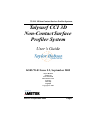
Talysurf CCI 3D
Non-Contact Surface
Profiler System
User’s Guide
K505/70-01 Issue 5.2, September 2005
Taylor Hobson
PO Box 36
New Star Road
Thurmaston Lane
Leicester
LE4 9JQ
England
Copyright © 2005
Issue 5.2 September 2005
Page 1
TS CCI 3D Non-Contact Surface Profiler Systems
Page 2
Issue 5.2 September 2005
TS CCI 3D Non-Contact Surface Profiler Systems
Taylor Hobson's License
License statement and limited warranty
IMPORTANT - READ CAREFULLY
This License Statement and Limited Warranty constitutes a legal
agreement ("License Agreement") between you (either as an individual or a single entity) and Taylor Hobson Ltd ("THL") for the
software product ("Software") identified above, including any
software, media, and accompanying on-line or printed documentation.
BY INSTALLING, COPYING, OR OTHERWISE USING THE
SOFTWARE, YOU AGREE TO BE BOUND BY ALL OF THE
TERMS AND CONDITIONS OF THIS LICENSE AGREEMENT. If you are the original purchaser of the Software and you
do not agree with the terms and conditions of this License Agreement promptly return the unused Software to the place from which
you obtained it for a full refund.
The terms of this License Agreement apply irrespective of how,
when and by whom the software was installed on a computer, irrespective of the ownership of the computer, and irrespective of
whether it is connected to THL supplied equipment or not.
LICENSE GRANT
Subject to the payment of the applicable license fee and your
acceptance of the terms and conditions of this License Agreement,
THL grants you the right to use the Software in the manner provided below.
Issue 5.2 September 2005
Page 3
TS CCI 3D Non-Contact Surface Profiler Systems
OWNERSHIP AND COPYRIGHT
This Software is owned by THL or its suppliers and is protected by
copyright law and international copyright treaty. Therefore you
must treat this Software like any other copyrighted material, (e.g. a
book), except that you may either make one copy of the Software
solely for backup or archival purposes or transfer the Software to a
single hard disk provided you keep the original solely for backup
or archival purposes.
Except as provided in this License Agreement, you may not transfer, rent, lease, lend, copy, modify, translate, sublicense, timeshare or electronically transmit or receive the Software, media or
documentation. You acknowledge that the Software in source code
form remains a confidential trade secret of THL or its suppliers
and therefore you agree not to modify the Software or attempt to
decipher, de-compile, disassemble or reverse engineer the Software, except to the extent applicable laws specifically prohibit
such restriction.
You shall not remove or permit to be removed any copyright
notice on the software nor any statement of ownership which may
be affixed thereto.
USE
The Software is licensed as a single product; it may not be
installed on more than one computer at a time.
The TalyMap Software is protected by a security system tied to the
hardware of the computer on which it is installed. Once the software is loaded on a computer a code (the "Activation Code") must
be requested from THL and entered into the computer to enable
the functionality of the software. THL will make the Activation
Code available to you on condition you provide THL with proof of
purchase of the Software if requested to do so by THL.
Page 4
Issue 5.2 September 2005
TS CCI 3D Non-Contact Surface Profiler Systems
In the event that the TalyMap Software is moved to another computer or items of the hardware are altered such that the Activation
Code is no longer valid, a replacement Activation Code will be
required. THL will provide a replacement Activation Code against
reasonable assurances from you that the Software has not been
copied in violation of this Agreement.
UPDATES
If you purchased this Software as an upgrade, it constitutes a single product together with the product that you upgraded, and may
not be used to increase the total number of licensed copies of the
Software. You may use the upgraded product only in accordance
with this License Agreement and you may not transfer this Software or the product you upgraded unless they are transferred
together as a single product.
TERM
The License Agreement is effective for an unlimited duration
unless and until earlier terminated as set forth herein. This License
Agreement will terminate automatically if you fail to comply with
any of the limitations or other requirements specified herein. Upon
any expiration or termination of the License Agreement you must
destroy all copies of the Software.
ACCESS
You shall permit THL's representatives to have access at all reasonable times to the Software and any records relating to its use.
LIMITED WARRANTY AND LIMITATION OF
LIABILITY
THL warrants that the Software, as updated and when properly
used, will perform substantially in accordance with its accompanying documentation, and the Software media will be free from
Issue 5.2 September 2005
Page 5
TS CCI 3D Non-Contact Surface Profiler Systems
defects in materials and workmanship, for a period of ninety (90)
days from the date of receipt. Any implied warranties on the Software are limited to ninety (90) days. Some states or jurisdictions
do not allow limitations on duration of an implied warranty, so the
above limitation may not apply to you.
THL's and its suppliers' entire liability and your exclusive remedy
shall be, at THL's option, either (a) return of the price paid, or (b)
repair or replacement of the Software that does not meet the Limited Warranty. This Limited Warranty is void if Software fails as a
result of accident, abuse, or misapplication. Any replacement
Software will be warranted for the remainder of the original warranty period or thirty (30) days, whichever is longer.
AS THE PRICE FOR THE LICENSE IS UNRELATED TO A
PARTICULAR USE TO WHICH THE LICENSEE INTENDS TO
APPLY THE SOFTWARE, THL MAKES NO WARRANTIES IN
RELATION TO THE PERFORMANCE OF THE SOFTWARE
OR ITS FITNESS FOR ANY PARTICULAR PURPOSE.
SAVE AS PROVIDED IN THIS CLAUSE,THL AND ITS SUPPLIERS DISCLAIM ALL OTHER WARRANTIES, EITHER
EXPRESS OR IMPLIED, INCLUDING, BUT NOT LIMITED
TO, ANY IMPLIED WARRANTIES OF MERCHANTABILITY,
FITNESS FOR A PARTICULAR PURPOSE, NON-INFRINGEMENT OR TITLE, WITH REGARD TO THE SOFTWARE AND
THE ACCOMPANYING DOCUMENTATION. THIS LIMITED
WARRANTY GIVES YOU SPECIFIC LEGAL RIGHTS. YOU
MAY HAVE OTHERS, WHICH VARY FROM STATE TO
STATE OR JURISDICTION TO JURISDICTION.
SAVE THAT ITS LIABILITY FOR PERSONAL INJURY OR
DEATH CAUSED BY ITS OR ITS AGENTS' NEGLIGENCE
SHALL NOT BE AFFECTED IN ANY WAY NEITHER THL
NOR ITS SUPPLIERS SHALL BE LIABLE FOR ANY DAMPage 6
Issue 5.2 September 2005
TS CCI 3D Non-Contact Surface Profiler Systems
AGES WHATSOEVER (INCLUDING, WITHOUT LIMITATION, DAMAGES FOR LOSS OF BUSINESS PROFITS,
BUSINESS INTERRUPTION, LOSS OF BUSINESS INFORMATION, OR ANY OTHER PECUNIARY LOSS) ARISING
OUT OF THE USE OF OR INABILITY TO USE THIS THL
PRODUCT EVEN IF THL HAS BEEN ADVISED OF THE POSSIBILITY OF SUCH DAMAGES.
GENERAL PROVISIONS
This License Agreement may only be modified in writing signed
by you and an authorised officer of THL. If any provision of this
License Agreement is found void or unenforceable, the remainder
will remain valid and enforceable according to its terms. If any
remedy provided is determined to have failed for its essential purpose, all limitations of liability and exclusions of damages set forth
in the Limited Warranty shall remain in effect.
THIRD PARTIES
For the avoidance of doubt nothing in this Agreement shall confer
on any third party any benefit or right to enforce this Agreement.
ENTIRE AGREEMENT
THL shall not be liable to you for loss arising from or in connection with any representations agreements statements or undertakings made prior to this License Agreement
APPLICABLE LAW
This License Agreement shall be interpreted in accordance with
the laws of England and you hereby submit to the exclusive jurisdiction of the English Courts.
Issue 5.2 September 2005
Page 7
TS CCI 3D Non-Contact Surface Profiler Systems
TAYLOR HOBSON LTD CUSTOMER CONTACTS
If you have any questions concerning these terms and conditions,
or if you would like to contact Taylor Hobson for any other reason
please check for your local contact on our website at www.taylorhobson.com or write to the company at Taylor Hobson Ltd, PO
Box 36, 2 New Star Road, Leicester LE4 9JQ, United Kingdom,
Tel +44 (0)116 276 3771.
Page 8
Issue 5.2 September 2005
TS CCI 3D Non-Contact Surface Profiler Systems
Taylor Hobson's License ...................................3
License statement and limited warranty.......... 3
LICENSE GRANT ......................................... 3
OWNERSHIP AND COPYRIGHT................ 4
USE ................................................................. 4
UPDATES....................................................... 5
TERM.............................................................. 5
ACCESS.......................................................... 5
LIMITED WARRANTY AND LIMITATION OF
LIABILITY ..................................................... 5
GENERAL PROVISIONS ............................. 7
THIRD PARTIES ........................................... 7
ENTIRE AGREEMENT................................. 7
APPLICABLE LAW ...................................... 7
TAYLOR HOBSON LTD CUSTOMER
CONTACTS.................................................... 8
Chapter 1 Safety ............................. 1-1
Important Safety Information ..........................1-1
Warnings, Cautions and notes.........................1-1
Safety Information ..........................................1-2
Chapter 2 System Requirements
and Specification ............................. 2-1
Talysurf CCI ......................................................2-1
Electrical Supply .............................................2-1
Environmental Conditions ..............................2-1
Issue 5.2 September 2005
Page i
TS CCI 3D Non-Contact Surface Profiler Systems
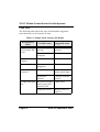
Talysurf CCI 6000 System Specification ........ 2-2
Vertical resolution (best) ............................ 2-2
RMS repeatability (Z) ................................ 2-2
Measurement range (X,Y) .......................... 2-2
Lateral sampling resolution (X,Y) ............. 2-2
Step height repeatability ............................ 2-2
Linearity (Z) ............................................... 2-2
Maximum Resolution (dependant on mode) 2-2
Resolution of Manual Z stage .................... 2-2
Reflectivity ................................................. 2-3
Stage Range ............................................... 2-3
Component size .......................................... 2-3
Component size .......................................... 2-3
Component weight ..................................... 2-3
Vertical scanning range ............................. 2-3
Talysurf CCI 2000 System Specification ........ 2-4
Vertical resolution (best) ........................... 2-4
RMS repeatability (Z) ................................ 2-4
Measurement range (X,Y) .......................... 2-4
Lateral sampling resolution (X,Y) ............. 2-4
Step height repeatability ............................ 2-4
Linearity (Z) ............................................... 2-4
Maximum Resolution (dependant on mode) 2-4
Resolution of Manual Z stage .................... 2-4
Reflectivity ................................................. 2-4
Stage Range ............................................... 2-4
Component size .......................................... 2-4
Component size .......................................... 2-4
Component weight ..................................... 2-4
Vertical scanning range ............................. 2-5
Page ii
Issue 5.2 September 2005
TS CCI 3D Non-Contact Surface Profiler Systems
Chapter 3 Installation Instructions for
the Talysurf CCI instruments ....... 3-1
Introduction .......................................................3-1
Unpacking the Instrument ................................3-1
Siting the instrument .........................................3-2
Details for recommended desk (CCI 2000) ....3-2
Instrument height (CCI6000) ..........................3-3
Recommended Siting Plan (CCI 6000)...........3-4
Recommended positioning of the components3-5
Clean area........................................................3-5
Draughts ..........................................................3-5
Temperature Gradients....................................3-6
Vibration .........................................................3-6
Power Supply ..................................................3-6
Hardware Installation (CCI 6000) ...................3-7
System Components........................................3-7
M112/3505-XX TALYSURF CCI 6000
MEASURING INSTRUMENT .....................3-7
Computer options ........................................3-9
Options ............................................................3-10
Lenses ..........................................................3-10
Talymap options ..........................................3-10
Stages options ..............................................3-11
Piezo options ...............................................3-12
Accessories......................................................3-13
Calibration/Setting Standards .....................3-13
Issue 5.2 September 2005
Page iii
TS CCI 3D Non-Contact Surface Profiler Systems
Printers ....................................................... 3-15
Furniture ..................................................... 3-16
Hardware Installation (CCI 2000) ................... 3-17
System Components ....................................... 3-17
M112/3613-XX TALYSURF CCI 2000
MEASURING INSTRUMENT ..................... 3-17
Computer options ........................................ 3-18
Options ........................................................... 3-19
Lenses ......................................................... 3-19
Talymap options .......................................... 3-19
As for CCI 6000 .......................................... 3-19
Stages options ............................................. 3-20
Piezo options ............................................... 3-21
Accessories ..................................................... 3-21
Installation procedure ..................................... 3-22
Adjusting Anti Vibration air mounts
(CCI 6000 only).............................................. 3-22
Interconnection diagram (CCI 6000).............. 3-23
Interconnection diagram (CCI 2000).............. 3-25
Installing/Upgrading software ........................ 3-26
Networking of the PC's................................... 3-26
User Rights ..................................................... 3-26
Setting Up the System .................................... 3-26
System pre-packing instructions..................... 3-27
Chapter 4 Operating Instructions .4-1
Introduction ....................................................... 4-1
Page iv
Issue 5.2 September 2005
TS CCI 3D Non-Contact Surface Profiler Systems
Description of instrument controls ..................4-2
Z stage control (manual) .................................4-2
X,Y and Tip tilt stage controls (manual).........4-2
Motorised X,Y stage controls .........................4-3
Automatic X,Y,Z stage controls .....................4-3
Light Unit Controls .........................................4-4
Description of User Interface ............................4-5
User Interface Introduction .............................4-5
Configuration screen .......................................4-6
Lens .............................................................4-6
Mode ...........................................................4-7
Zoom. ..........................................................4-7
Scanning Speed ..........................................4-8
Special Options ..........................................4-8
Fringe set up screen.........................................10
Contrast reference ......................................4-11
Gradient enhance .......................................4-11
Cross hair ...................................................4-11
Range ..........................................................4-11
Bottom ........................................................4-11
Estimated time ............................................4-11
Scan setting buttons ....................................4-12
The slider ....................................................4-12
Light Level Setting ......................................4-12
Measurement screen........................................4-13
Computation settings ..................................4-13
Settings .......................................................4-14
Measure ......................................................4-14
Measurement Type. ....................................4-15
Frame sequence ..........................................4-15
Issue 5.2 September 2005
Page v
TS CCI 3D Non-Contact Surface Profiler Systems
Axis Control Screen ....................................... 4-16
Move To Position ....................................... 4-16
Z Move ....................................................... 4-17
Step/Nudge Move ....................................... 4-17
Refresh Joystick ......................................... 4-17
Load Component ........................................ 4-17
Z Bottom End Stop ..................................... 4-17
Toolbar ........................................................... 4-18
Calibrate button ......................................... 4-18
Diagnostics button ..................................... 4-18
Measure button .......................................... 4-18
Help button. ............................................... 4-18
Stop button ................................................. 4-18
Start a pattern measurement. ...................... 4-19
Start a HDD Slider measurement .............. 4-19
Main menus .................................................... 4-20
File menu ................................................... 4-20
Actions menu .............................................. 4-20
User ............................................................ 4-20
Tools .......................................................... 4-20
Help ............................................................ 4-21
How Do I Start The Instrument ....................... 4-22
How Do I Change My Password ...................... 4-22
How Do I Configure My Instrument ............... 4-23
Mode............................................................... 4-23
‘XY’ mode .................................................. 4-23
'xyz' mode ................................................... 4-23
'Z' mode ...................................................... 4-23
Page vi
Issue 5.2 September 2005
TS CCI 3D Non-Contact Surface Profiler Systems
Zoom ...............................................................4-23
Scanning Speeds .............................................4-24
Special options ................................................4-24
How Do I Calibrate My Instrument ................4-25
Calibration Types ............................................4-25
Calibration Wizard ..........................................4-25
XY Calibration (X and Y Gains) ...................4-27
Artefact .......................................................4-27
Sequence .....................................................4-27
Application .................................................4-28
Z Calibration (Z Gain) ...................................4-29
Artefact .......................................................4-29
Sequence .....................................................4-29
50mm step height procedure ......................4-31
Advanced Z Datum Correction (Z Form from
multiple measurements) ..................................4-32
Artefact .......................................................4-32
Sequence .....................................................4-32
Z Datum Correction (Z Form from a single
measurement) ..................................................4-34
Artefact .......................................................4-34
Sequence .....................................................4-34
Application .................................................4-34
Calibration Artefacts .......................................4-34
How Do I Make a basic Measurement .............4-37
Selecting a lens................................................4-37
Changing lens .............................................4-38
Positioning the component..............................4-38
Configure the Instrument ................................4-38
Issue 5.2 September 2005
Page vii
TS CCI 3D Non-Contact Surface Profiler Systems
Focus on Surface, Set Light Levels and Find
Fringes ............................................................ 4-39
Set Scan Length and position ......................... 4-41
Scan setting buttons ................................... 4-41
The slider ................................................... 4-42
Setting TalyMap options ................................ 4-42
Save 3D Data File As: ............................... 4-42
Auto-increment .......................................... 4-43
New document ............................................ 4-43
Apply template to document ....................... 4-43
Auto run TalyMap ...................................... 4-43
Show TalyMap button ................................ 4-43
Making a Scan ................................................ 4-43
Basic Analysis ................................................ 4-43
Calibration ...................................................... 4-44
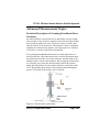
Advanced Measurement Topics ....................... 4-45
Technical Description of Scanning Broadband
Interferometry................................................. 4-45
Sample Preparation for Measurement ............ 4-46
Good Metrology Practice for CCI .................. 4-46
Finding Fringes and Use of Levelling Stages. 4-47
Finding fringes ........................................... 4-47
Levelling a component ............................... 4-48
Pre-Analysis of Results, Assessment of missing
Data etc. .......................................................... 4-49
Data Binning................................................... 4-49
How do I use the Special Options .................... 4-50
Data Output Mode (Low Noise)..................... 4-50
Scan Type. ...................................................... 4-51
Page viii
Issue 5.2 September 2005
TS CCI 3D Non-Contact Surface Profiler Systems
Post Threshold.................................................4-51
Basic TalyMap Functionality ...........................4-52
Using the 2.5x lens .............................................4-54
Interconnection of Piezo Servo Amplifier (2.5x
lens) and Installation of lens ...........................4-54
Installation of lens ......................................4-54
Using the lens .............................................4-56
Pattern measurement ........................................4-57
Pattern Control ................................................4-57
Pattern Execution ............................................4-58
Movement: ..................................................4-58
Measurement/Analysis: ..............................4-58
Pattern File ......................................................4-59
HDD Slider Measurement .................................4-61
Slider measurement.........................................4-62
Slider Holder Control......................................4-62
Slider Definition Set-up ..................................4-62
Slider File Format ...........................................4-63
Slider Results File ...........................................4-66
Lenses..............................................................4-67
Power lead.......................................................4-67
Chapter 5 Maintenance Procedures
and Service Support ....................... 5-1
Cleaning and Routine maintenance .................5-1
Issue 5.2 September 2005
Page ix
TS CCI 3D Non-Contact Surface Profiler Systems
General Cleaning ............................................ 5-1
Lens Cleaning ................................................. 5-1
PC Anywhere ..................................................... 5-2
Service support and Spares .............................. 5-2
Spares ............................................................. 5-2
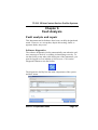
Chapter 6 Fault Analysis ................6-1
Fault analysis and repair .................................. 6-1
Software diagnostics....................................... 6-1
Fault table ....................................................... 6-2
Bulb replacement procedure........................... 6-4
Lamp replacement for alternative
illuminator type .............................................. 6-5
Fault reporting .................................................. 6-7
Chapter 7 Accessories .....................7-1
112-3350-02 - Instrument Desk...................... 7-1
Dimensions ................................................. 7-1
K505-71 - CCI User Manual For Clean
Rooms............................................................. 7-1
K505-72 - CCI Quick Reference Guide For Clean
Rooms............................................................. 7-1
112-3348-01 - Projector Lamp For
Illuminator ...................................................... 7-1
112-3323-01 - Lateral Calibration Standard.. 7-1
Description ................................................. 7-1
Page x
Issue 5.2 September 2005
TS CCI 3D Non-Contact Surface Profiler Systems
Specification: ...............................................7-1
112-3498-01 - Lateral Calibration Standard
with traceable calibration ................................7-2
112-3298-01 - Step Height Calibration
Standard 5mm .................................................7-2
Description ..................................................7-2
112-3499-01 - Step Height Calibration
Standard 50mm with traceable calibration......7-2
Description ..................................................7-2
112-3297-01 - Calibration Flat .......................7-3
Description ..................................................7-3
Specification: ...............................................7-3
112-2902-01 - HP Deskjet Printer ..................7-3
Description ..................................................7-3
Important .....................................................7-3
112/2696-01 - LaserJet Printer........................7-4
112-3217-01 - HP Business Inkjet
Printer 2000.....................................................7-4
112-3290-01 - Objective lens..........................7-4
112-3291-01 - Objective lens..........................7-4
112-3292-01 - Objective lens..........................7-4
112-3293-01 - Objective lens..........................7-5
112-3294-01 - Objective lens..........................7-5
Issue 5.2 September 2005
Page xi
TS CCI 3D Non-Contact Surface Profiler Systems
Page xii
Issue 5.2 September 2005
TS CCI 3D Non-Contact Surface Profiler Systems
Chapter 1
Safety
Important Safety Information
Before operating this instrument, the operator should be familiar
with this handbook and the contents of the "On-Line" Help facility
within the Software, and understand the operation of the instrument.
Note: Please refer to the Installation CD for the latest version of
the User Guide.
Note: Not all of the features described are available on all systems.
Note: Please retain this handbook for future reference.
Warnings, Cautions and notes
Warning: If the actions indicated in a “WARNING”
are not complied with, personal injury or death could result.
A Warning statement will typically describe the potential hazard, and the measures that must be followed to reduce the hazard.
Caution: If the action specified in the “CAUTION” is not
complied with, damage to your equipment could result.
Note: A “NOTE” provides supplementary information, emphasizes a point or procedure, or gives a tip for easier operation.
Issue 5.2 September 2005
Page 1-1
TS CCI 3D Non-Contact Surface Profiler Systems
Safety Information
The Talysurf CCI system is designed to be safe when the following conditions apply:•
The system is located indoors in dry conditions.
•
The altitude does NOT exceed 2000m.
Warnings
The following must be observed, failure to do so may expose
the operator or other persons to risk of serious injury or
death:•
It is essential that the electrical supply to this instrument
consists of a THREE WIRE SYSTEM in which one wire is
the earth. The instrument must NEVER be connected to a
two wire system with, or without, a separate earth. Failure
to connect the system to the correct type of supply could
lead to an increased fire risk and even result in severe
injury or death.
•
The electrical supply to the instrument should be CONNECTED VIA A SEPARATE MAINS ISOLATING
SWITCH and that prior to connection this switch is set to
the "OFF" position. Failure to do so could expose you to
severe injury or even death.
•
The mains lead MUST BE DISCONNECTED before making any system interconnections or attempting to change a
fuse. Failure to do so could result in severe injury or even
death.
Page 1-2
Issue 5.2 September 2005
TS CCI 3D Non-Contact Surface Profiler Systems
•
The CCI is a heavy item, weighing 210kg (depending upon
model). Exercise extreme caution when moving the instrument. Failure to do so could result in severe injury or even
death. Ideally you should use wheels if provided, a pallet
truck or a fork lift to move the instrument. Desktop versions have handles provided for lifting. It is recommended
that four people are used to move the base. Screw in carrying handles are provided for use with moving the base.
•
DO NOT attempt to lift the column by the leadscrew or the
handwheel if fitted. Failure to lift the column in the correct
manner could result in severe injury or even death.
•
DO NOT under any circumstances leave a column standing in the vertical position if it has not been bolted into
place. Failure to secure the column could result in severe
injury or even death.
Issue 5.2 September 2005
Page 1-3
TS CCI 3D Non-Contact Surface Profiler Systems
Cautions
•
If it is required to PAT test the equipment for earth continuity, it should ONLY be tested at a maximum test current
of 200mA. Test currents above this could damage the sensitive electronic equipment within the system.
•
Before placing the Measuring head on the carriage adaptor
plate, ensure that the adaptor plate is firmly secured to the
column carriage.
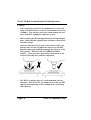
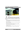
•
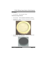
When the objective lens is close to the surface of the component, take care not to impact the objective or the PZT
into the component as this may damage the objective or the
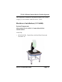
PZT scanner. THIS IS NOT COVERED BY WARRANTY. There may be a piezo buzzer that warns of the
contact of the objective with the component.
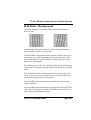
•
The PZT (see picture above) is easily damaged and very
expensive. DO NOT PUT any undue force on the the PZT
and when transporting, remove and pack in a sealed bag
with silica gel.
Page 1-4
Issue 5.2 September 2005
TS CCI 3D Non-Contact Surface Profiler Systems
Chapter 2
System Requirements
and Specification
Talysurf CCI
Electrical Supply
•
Mains supply voltage: 90 to 240VAC
Caution.
The light unit and PC may have a switchable voltage selector.
Ensure that it is set to the correct setting before connecting
and switching on.
•
Frequency: 50/60 Hz
•
Power Consumption: 500VA Maximum
This equipment is intended for installation category (low-voltage
category) II, in accordance with EN 61010-1 (2001).
Note: For details of the power requirements for the computer
and any accessories that do not derive their power from the CCI
system, refer to the manufacturer's documentation.
Environmental Conditions
For operation within performance specifications,
Ambient temperature range:
•
Operating: +15oC to +30oC
Issue 5.2 September 2005
Page 2-1
TS CCI 3D Non-Contact Surface Profiler Systems
•
Storage: -10oC to +50oC
Ambient relative humidity:
•
Operating:<70% non-condensing
•
Storage:10% to 70% non-condensing
Caution:
The piezo unit is very sensitive to high humidity and may be
damaged if operated outside of this range. Take extra care
when moving from a cold area to a humid environment.
Temperature gradient:<2oC/hour
Air flow: <0.5m/s
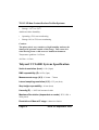
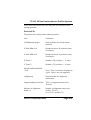
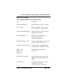
Talysurf CCI 6000 System Specification
Vertical resolution (best). 0.1Å (10pm)
RMS repeatability (Z). 0.03Å (3pm)
Measurement range (X,Y). 0.36mm - 7.0mm
Lateral sampling resolution (X,Y). 0.35 µm (best)
Step height repeatability . 0.1nm (best)
Linearity (Z). +/-0.05%of measured value
Maximum Resolution (dependant on mode). X/Y: 1024 x
1024 pixels
Resolution of Manual Z stage. 0.4mm/revolution
Page 2-2
Issue 5.2 September 2005
TS CCI 3D Non-Contact Surface Profiler Systems
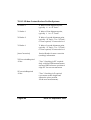
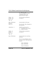
Reflectivity. Greater than or equal to 0.1%
Stage Range.
•
X and Y: 25mm (Manual) OR
112 x 75mm (Motorised option) OR
150m x 150mm (Auto option 1) OR
250mm x 200mm (Auto option 2)
•
Z (column): 100mm
•
θx and θy: +/-4o
Component size. X and Y: up to 300mm
Component size. Z: up to 100mm
Component weight. up to 10kg
Vertical scanning range. up to 100µm or 400µm
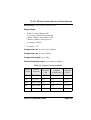
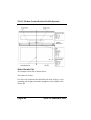
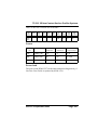
Table 2-1: Objective lenses available
Objecti
ve Lens
Field of
View/mm
Working
Distance/
mm
Lateral
sampling
resolution/µm
Maximum
componen
t slope/°
2.5x
7.0 x 7.0
10.3
7.03
+/-2.0
5x
3.6 x 3.6
9.3
3.5
+/-3.5
10x
1.80 x 1.80
7.4
1.76
+/- 8
20x
0.90 x 0.90
4.7
0.88
+/- 14.5
50x
0.36 x 0.36
3.4
0.35
+/- 22
Issue 5.2 September 2005
Page 2-3
TS CCI 3D Non-Contact Surface Profiler Systems
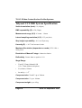
Talysurf CCI 2000 System Specification
Vertical resolution (best). 1Å (100pm)
RMS repeatability (Z). 0.5Å (50pm)
Measurement range (X,Y). 0.36mm - 1.8mm
Lateral sampling resolution (X,Y). 0.35 µm (best)
Step height repeatability . 0.1% on 50µm step
Linearity (Z). +/-0.17%of measured value
Maximum Resolution (dependant on mode). X/Y: 1024 x
1024 pixels
Resolution of Manual Z stage. 0.4mm/revolution
Reflectivity. Greater than or equal to 0.1%
Stage Range.
•
X and Y: 25mm (Manual) OR
112 x 75mm (Motorised option)
•
Z (column): 100mm
•
θx and θy: +/-4o
Component size. X and Y: up to 300mm
Component size. Z: up to 100mm
Component weight. up to 10kg
Page 2-4
Issue 5.2 September 2005
TS CCI 3D Non-Contact Surface Profiler Systems
Vertical scanning range. up to 100µm or 400µm
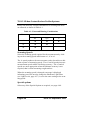
Table 2-2: Objective lenses available
Objective
Lens
Field of
View/mm
Working
Distance/mm
Lateral sampling
resolution/µm
Maximum component
slope/°
10x
1.80 x
1.80
7.4
1.76
+/- 3
20x
0.90 x
0.90
4.7
0.88
+/- 10
50x
0.36 x
0.36
3.4
0.35
+/- 12
Issue 5.2 September 2005
Page 2-5
TS CCI 3D Non-Contact Surface Profiler Systems
Page 2-6
Issue 5.2 September 2005
TS CCI 3D Non-Contact Surface Profiler Systems
Chapter 3
Installation Instructions for the
Talysurf CCI instruments
Introduction
Talysurf CCI instruments are initially installed by a representative
of Taylor Hobson Limited. Any subsequent moving and re-installation should also be carried out by a representative of Taylor Hobson or a suitably trained person. This must be done with care for
the instrument and consideration for its applications and location.
Having completed the system installation, all details of the basic
operation of the CCI Software are obtained by reference to this
handbook or the software On-Line Help facility. In case of any
queries or problems Taylor Hobson Limited can be contacted at
the addresses shown at the back of this handbook.
Note: Please retain this handbook for future reference.
Unpacking the Instrument
Installation is carried out by a service engineer, or a representative,
of Taylor Hobson Limited.
Caution:
•
Please DO NOT unpack your instrument, or any associated
products or accessories, unless with a prior agreement with
a service engineer or representative of Taylor Hobson Limited.
Issue 5.2 September 2005
Page 3-1
TS CCI 3D Non-Contact Surface Profiler Systems
Siting the instrument
The overall accuracy of measurement results will be influenced by
environmental conditions, particularly; draughts, vibration and the
rate at which the ambient temperature changes. The choice of
location depends on the application requirement. However, to
ensure that the optimum performance is achieved, wherever possible, the instrument hardware should be installed with consideration given to the surroundings in which it will operate.
The following items must be considered when siting the instrument;
Details for recommended desk (CCI 2000)
The desk is to be provided by the customer.
The desk top should be a minimum of 600mm square and able to
safely support a minimum weight of 200kg.
Page 3-2
Issue 5.2 September 2005
TS CCI 3D Non-Contact Surface Profiler Systems
A seperate desk is required to support the computer and electronics equipment. This should nominally be 900mm wide.
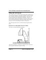
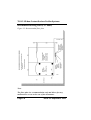
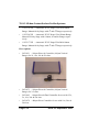
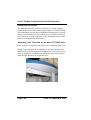
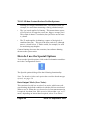
Instrument height (CCI6000)
Figure 3-1 Instrument height
Issue 5.2 September 2005
Page 3-3
TS CCI 3D Non-Contact Surface Profiler Systems
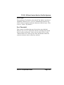
Recommended Siting Plan (CCI 6000)
Figure 3-2 Recommended floor plan
Note.
The floor plan is a recommendation only and allows for easy
maintenance access to the rear of the instrument.
Page 3-4
Issue 5.2 September 2005
TS CCI 3D Non-Contact Surface Profiler Systems
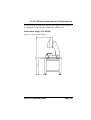
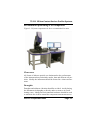
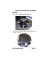
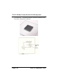
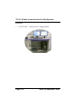
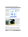
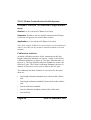
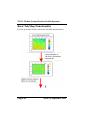
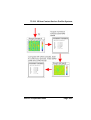
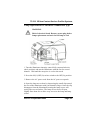
Recommended positioning of the components
Figure 3-3 System components in their recommended location
Clean area
All forms of airborne particle are detrimental to the performance
of the instrument but particularly smoke, dust and airborne oil particles. Ideally the instrument should be located in a clean environment.
Draughts
Draughts and airborne vibration should be avoided. Avoid placing
the instrument in draughts or directly under or next to air conditioning vents. Ideally an Environmental enclosure should be used
to minimise the airflow around the component measurement area.
Issue 5.2 September 2005
Page 3-5
TS CCI 3D Non-Contact Surface Profiler Systems
Temperature Gradients
Avoid siting the instrument in areas that have a very rapid temperature gradient, and avoid siting near windows or skylights where
sunlight may fall on the instrument.
Areas that experience temperature gradients of over 2°C/hour are
not ideal for measurement.
Vibration
Both air borne and ground based vibration is particularly detrimental for the measurement of surface texture. It is recommended
that all sources of vibration are removed. All Talysurf CCI instruments are supplied with anti-vibration mounts. It is also important
that cables should be run away from sources of vibration and
located where they cannot be kicked or jarred.
Power Supply
It is important that a clean power supply should be provided to the
instrument. If in doubt, many computer peripheral dealers can
supply a suitable Uninterruptible Power Supply (U.P.S.).
The power supply voltage must conform to the following
•
Mains supply voltage: 90 to 240VAC
Caution.
The light unit and PC may have a switchable voltage selector.
Ensure that it is set to the correct setting before connecting
and switching on.
•
Frequency: 50/60 Hz
•
Power Consumption: 500VA Maximum
Page 3-6
Issue 5.2 September 2005
TS CCI 3D Non-Contact Surface Profiler Systems
This equipment is intended for installation category (low-voltage
category) II, in accordance with EN 61010-1 (2001).
Hardware Installation (CCI 6000)
System Components
M112/3505-XX TALYSURF CCI 6000 MEASURING
INSTRUMENT.
comprising:
•
K510/3038-XX - Granite Base with Steel Base Frame and
Pneumatic AV
Issue 5.2 September 2005
Page 3-7
TS CCI 3D Non-Contact Surface Profiler Systems
•
112/3493-XX - CCI Measuring Unit consisting of
- TalySurf CCI Measurement Head
- External CCI Light Source with filter changer
•
112/3416-XX - CCI Application Software Pack
•
K505/70 - CCI User Guide
•
K505/72CCI - Quick Reference Guide for Clean Rooms
Page 3-8
Issue 5.2 September 2005
TS CCI 3D Non-Contact Surface Profiler Systems
•
112/3348-XX - Light Source Bulb (Spare)
•
600-14 - Exploring Surface Texture
•
K501-3065-XX - Power Distribution Unit Assembly
Computer options.
•
265-1035E Personal Computer, English version
•
265/1078E Personal Computer, English version Dual Monitor
Issue 5.2 September 2005
Page 3-9
TS CCI 3D Non-Contact Surface Profiler Systems
Options
Lenses.
•
112/3290-XX - 2.5x Objective Lens 7.0mm x 7.0mm field of
view see note
•
112/3291-XX - 5x Objective Lens 3.6mm x 3.6mm field of
view
•
112/3292-XX - 10x Objective Lens 1.8mm x 1.8mm field of
view
•
112/3293-XX - 20x Objective Lens 0.9mm x 0.9mm field of
view
•
112/3294-XX - 50x Objective Lens 0.36mm x 0.36mm field
of view
Note: 2.5x lens will not operate with standard piezo 265/1031,
use either 265/1073 (2.5 only) or 265/1063 (all lenses)
Talymap options.
•
112/3579-01 Talymap Platinum
•
112/3580-01 Talymap Gold
•
112/3581-01 Talymap Silver
Page 3-10
Issue 5.2 September 2005
TS CCI 3D Non-Contact Surface Profiler Systems
Stages options.
•
112/3514-XX - Manual X/Y/Z/θx/θy Stage with
25,25,100mm, 4o and 4o Range respectively.
•
112/3515-XX - Motorised (joystick only) X/Y Stage
110x75mm Range, Manual Z/θx/θy Stage with 100mm, 4o and
4o Range respectively.
Issue 5.2 September 2005
Page 3-11
TS CCI 3D Non-Contact Surface Profiler Systems
•
112/3516-XX - Automatic X/Y/Z Stage 150x150x100mm
Range, Manual θx/θy Stage with 4o and 4o Range respectively.
•
112/3524-XX - Automatic X/Y/Z Stage 150x150mm Range,
Manual Z/θx/θy Stage with 100mm, 4o and 4o Range respectively.
•
112/3517-XX - Automatic X/Y/Z Stage 250x200x100mm
Range, Manual θx/θy Stage with 4o and 4o Range respectively.
Piezo options.
•
265/1031 - 100µm Piezo & Controller (100µm Vertical
Range) for 5x, 10x, 20x & 50x lens
•
265/1073 - 100µm Piezo & Controller (100µm Vertical
Range) for 2.5x lens
•
265/1063 - 100µm Piezo & Dual Controller for use with 2.5x,
5x, 10x, 20x & 50x lens
•
265/1079 - 400µm Piezo Controller for use with 10x, 20x &
50x lens
Page 3-12
Issue 5.2 September 2005
TS CCI 3D Non-Contact Surface Profiler Systems
Accessories
•
112/3560-XX - Environmental Cabinet
Calibration/Setting Standards.
•
112/3323-XX - Lateral Calibration Standard for all lenses
•
112/3498-XX - Lateral Calibration Standard with Traceable
Calibration Certificate
•
112/3298-XX - 5µm Step Height Calibration Standard with
Traceable Calibration Certificate
Issue 5.2 September 2005
Page 3-13
TS CCI 3D Non-Contact Surface Profiler Systems
•
112/3499-XX - 50µm Step Height Calibration Standard with
Traceable Calibration Certificate
Page 3-14
Issue 5.2 September 2005
TS CCI 3D Non-Contact Surface Profiler Systems
•
112/3297-XX - Calibration Flat Mirror 0.2nm RMS with
Non-traceable Calibration Certificate
•
112/3507-XX - Calibration Flat Mirror 0.2nm RMS with
Traceable Calibration Certificate
Printers.
•
112/2902-XX - HP DeskJet Printer
•
112/2696-XX - LaserJet Printer
•
112/3217-XX - HP Business Inkjet Printer
Issue 5.2 September 2005
Page 3-15
TS CCI 3D Non-Contact Surface Profiler Systems
Furniture.
•
112/3350-XX - Talysurf CCI Computer Desk
Page 3-16
Issue 5.2 September 2005
TS CCI 3D Non-Contact Surface Profiler Systems
Hardware Installation (CCI 2000)
System Components
M112/3613-XX TALYSURF CCI 2000 MEASURING
INSTRUMENT.
comprising:
•
K510/3061-XX - Granite Base with Rubber AV Mounts, desk
mounted.
Issue 5.2 September 2005
Page 3-17
TS CCI 3D Non-Contact Surface Profiler Systems
•
112/3614-XX - CCI Measuring Unit consisting of
- TalySurf CCI Measurement Head.
•
112/3416-XX - CCI Application Software Pack
•
CCI User Guide
•
K505/72CCI - Quick Reference Guide for Clean Rooms
•
112/3348-XX - Light Source Bulb (Spare)
•
600-14 - Exploring Surface Texture
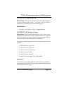
Computer options.
•
265-1101E Personal Computer, English version
Page 3-18
Issue 5.2 September 2005
TS CCI 3D Non-Contact Surface Profiler Systems
Options
Lenses.
•
112/3292-XX - 10x Objective Lens 1.8mm x 1.8mm field of
view
•
112/3293-XX - 20x Objective Lens 0.9mm x 0.9mm field of
view
•
112/3294-XX - 50x Objective Lens 0.36mm x 0.36mm field
of view
Talymap options. As for CCI 6000.
Issue 5.2 September 2005
Page 3-19
TS CCI 3D Non-Contact Surface Profiler Systems
Stages options.
•
112/3514-XX - Manual X/Y/Z/θx/θy Stage with
25,25,100mm, 4o and 4o Range respectively.
•
112/3515-XX - Motorised (joystick only) X/Y Stage
110x75mm Range, Manual Z/θx/θy Stage with 100mm, 4o and
4o Range respectively.
Page 3-20
Issue 5.2 September 2005
TS CCI 3D Non-Contact Surface Profiler Systems
Piezo options.
•
265-1099 - Piezo and controller. 100µm vertical range with
LVDT feedback.
Accessories
As for CCI 6000.
Issue 5.2 September 2005
Page 3-21
TS CCI 3D Non-Contact Surface Profiler Systems
Installation procedure
The installation process will be performed by a Taylor Hobson
Service Engineer or other similar representative of Taylor Hobson.
Any subsequent moving and re-installation should also be carried
out by a representative of Taylor Hobson or a suitably trained person. This must be done with care for the instrument and consideration for its applications and location.
Adjusting Anti Vibration air mounts (CCI 6000 only)
Place spirit level on granite base and level by adjusting frame feet.
Using a pump and the valves mounted on the front of the frame,
inflate each AV mount so that the diaphragm is level. (This is best
done by slightly over inflating and letting air out of the mount to
bring the base down to the required level).
Page 3-22
Issue 5.2 September 2005
TS CCI 3D Non-Contact Surface Profiler Systems
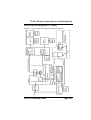
Interconnection diagram (CCI 6000)
Figure 3-3 Interconnection diagram (Manual System)
Issue 5.2 September 2005
Page 3-23
TS CCI 3D Non-Contact Surface Profiler Systems
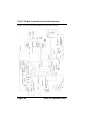
Figure 3-4 Interconnection diagram (Automatic System)
Page 3-24
Issue 5.2 September 2005
TS CCI 3D Non-Contact Surface Profiler Systems
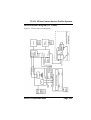
Interconnection diagram (CCI 2000)
Figure 3-5 Interconnection diagram
Issue 5.2 September 2005
Page 3-25
TS CCI 3D Non-Contact Surface Profiler Systems
Installing/Upgrading software
Full instructions for the installation of the application software are
provided on the Application software cd in the file ‘Talysurf CCI
Software Installation Procedure’.
Networking of the PC's
The PC needs to be set up with the one User (i.e. a single User
before and after networking).
If the PC is set-up with multiple users then it may be necessary to
do a separate installation of the Frame Grabber for each user. See
"Installing/Upgrading software" (page 3-26) for more information.
After a PC has been networked, it may not recognise the USB port
(Aladin) used for the Talymap dongle. To correct this, in Control
Panel>System>Hardware Devices>Device Manager>Ports,
remove the unrecognised USB Port. Then re-boot. If the Aladin
USB port is still unrecognised, select Control Panel>System>Hardware Devices>Add New Hardware Device.
User Rights
If a new user is added to the PC, then they need to be given ‘Power
User’ or ‘Administrator User’ rights, as the CCI Application software modifies files in the installation folder located in C:\program
Files.
Setting Up the System
Once the instrument is assembled and all the connections are made
the instrument is ready for use. The representative of Taylor Hobson will then set up the instrument for use.
Page 3-26
Issue 5.2 September 2005
TS CCI 3D Non-Contact Surface Profiler Systems
System pre-packing instructions
In the unlikely event that it becomes necessary to return the instrument, it should be carefully re-packaged. This should be performed by a representative of Taylor Hobson or a suitably
qualified person.
Issue 5.2 September 2005
Page 3-27
TS CCI 3D Non-Contact Surface Profiler Systems
Page 3-28
Issue 5.2 September 2005
TS CCI 3D Non-Contact Surface Profiler Systems
Chapter 4
Operating Instructions
Introduction
The Operating Instructions are organised into a number of sub-sections to enable you to find the information required quite quickly.
The first sub-sections describe the Instrument controls and the
User Interface in terms of the main screens, the toolbar and the
menus. This is provided as an introduction to the User Interface
and also to aid in the familiarisation with the instrument away
from the instrument itself.
Note: Not all procedures are available on all versions of the instrument.
The remaining sub-sections of this chapter describe ‘How Do I’
operations to enable you to calibrate the instrument, make a simple
measurement and then do more advanced operations with the
instrument.
The sub-sections are as follows:
•
Instrument Controls - Page 4-2.
•
User Interface - Page 4-4.
•
How Do I Change My Password - Page 4-16.
•
How Do I Configure My Instrument - Page 4-16.
•
How Do I Calibrate My Instrument - Page 4-18.
•
How Do I Make a Simple Measurement - Page 4-29.
•
Advanced Measurement Topics - Page 4-38.
Issue 5.2 September 2005
Page 4-1
TS CCI 3D Non-Contact Surface Profiler Systems
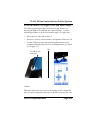
Description of instrument controls
Z stage control (manual)
Z Control, one each
side. Used to move
the measuring head
vertically so that the
camera image is in
focus and the fringes
are visible.
X,Y and Tip tilt stage controls (manual)
Y adjust
X adjust
Left hand tilt adjust θx
Right hand tilt adjust θy
The stage controls are used to angularly and laterally align a feature on the part with the measuring head.
Page 4-2
Issue 5.2 September 2005
TS CCI 3D Non-Contact Surface Profiler Systems
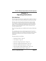
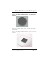
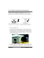
Motorised X,Y stage controls
The motorised X,Y stage is
the stand alone Axis control
and is driven by a stand
alone joystick, that has three
different speed set by the
switch on the joystick.
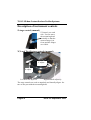
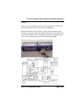
Automatic X,Y,Z stage controls
The left joystick controls
the movement in the XY plane and the right
hand joystick controls
the Z axis. The switch
on top of the joysticks
controls the speed of
movement, when activated the speed is the fastest of two speeds. When either switch is
pressed, all axes move at high speed. The stop button is located
between the two joysticks.
Issue 5.2 September 2005
Page 4-3
TS CCI 3D Non-Contact Surface Profiler Systems
Move to position:
moves the X, Y or Z
axis to the position
entered into the
appropriate box
when GO is clicked.
Z Move. moves
the Z axis in
the direction
specified at
low speed.
Step/Nudge move:
Moves the X, Y or
Z axis in steps as
defined by the value
entered into the
box.
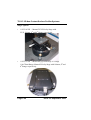
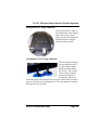
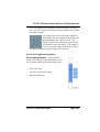
Light Unit Controls
The light level controls
are used to adjust the
light level that illuminates the component
being measured so that
an optimum level of
illumination is produced at the camera.
The light filter selector
has four settings:
I. - This is the broadest bandwidth filter used for normal measurements ie x1 speed.
II, III and IV - These settings represent the other filters that have
progressively narrower bandwidths. The narrower bandwidths
provided are used for fringe findings and fast measurements.
Page 4-4
Issue 5.2 September 2005
TS CCI 3D Non-Contact Surface Profiler Systems
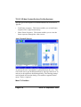
Description of User Interface
User Interface Introduction
The complete User Interface (UI) for the Talysurf CCI system consists of two main applications:
•
The Talysurf CCI Application, which controls the measurement and collection of measured data from the instrument.
•
The TalyMap application, which performs the actual analysis
of the measured data. TalyMap is described in the TalyMap
application On-Line Help
The Talysurf CCI application UI itself consists of a live video
screen and a surface screen both located on the left hand side of
the UI and accessed through tabs.
•
The live video screen displays a continually updated image of
the surface as seen through the CCI instrument camera.
•
The surface screen displays an image of the last measured surface.
•
The light level display can be used as a focus aid (see page 437) and to set the light level for measurements.
On the right hand side of the UI are three tabs that access the Configuration, Fringe Setup and Measurement areas. During the process of preparing to take and actually taking a measurement you
should step through the three tabs in order, that is configuration,
fringe setup and finally measurement. An additional tab is available for axis control if you have an automated system.
There are four buttons on the toolbar located above the live video/
surface screens. These icons are Calibration Wizard, Diagnostics,
Issue 5.2 September 2005
Page 4-5
TS CCI 3D Non-Contact Surface Profiler Systems
Measure and Help. An additional ‘Stop’ button is located on the
toolbar for an automated system.
There are five drop down menus located above the toolbar giving
access to the options File, Actions, Users, Tools and Help.
The status bar located at the bottom of the screen provides the user
with a summary of the measurement settings. If you have an automated system the axes positions and Z stop are displayed.
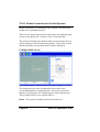
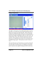
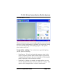
Configuration screen
The opening screen is the configuration screen and is also
accessed through the configuration tab. It provides you with a
number of user options for configuring the camera and the scan.
These include Field of view options such as:
Lens. The options available under this selection are:
Page 4-6
Issue 5.2 September 2005
TS CCI 3D Non-Contact Surface Profiler Systems
Note. The lens installed must match the setting on the Configuration screen.
•
2.5x - Field of view 7.0mm x 7.0mm
•
5x - Field of view 3.6mm x 3.6mm
•
10x - Field of view 1.8mm x 1.8mm
•
20x - Field of view 0.9mm x 0.9mm
•
50x - Field of view 0.36mm x 0.36mm
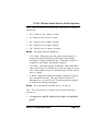
Mode. The mode options available are
•
‘XY’ Mode. This mode gives the greatest lateral detail. It
looks at all 1024x1024 pixels of the camera individually,
resulting in a longer calculation time. This mode would, for
example, be used where fine detail is required.
•
'xyz' mode. This mode applies 2x binning. This means that a
square of 2x2 pixels is combined to create one, bigger, average
pixel. This results in better Z resolution, but you loose out on
some x-y detail.
•
'Z' Mode. This mode applies 4x binning; a square of 4x4 pixels is combined into one. This gives the best result in Z,
although more x-y detail is lost. Z mode would, for example,
be used for measuring step heights.
Zoom. The zoom options available are x1, x2 and x4.
Note. The zoom function is a digital zoom with the following
parameters:
•
x1 zoom gives a full XY Field of View (FOV) of 1024x1024
pixels2
Issue 5.2 September 2005
Page 4-7
TS CCI 3D Non-Contact Surface Profiler Systems
•
x2 zoom gives a reduced XY FOV of 512x512 pixels2
•
x4 zoom gives a reduced XY FOV of 256x256 pixels2
There is also a zoom function in the TalyMap Analysis software,
refer to the TalyMap Operating Instructions or on-line help.
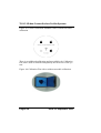
When the x2 and x4 zoom is selected, the area of interest can be
moved by clicking and holding on the small blue square and dragging to a new location. Upon releasing the video will display at
the new location.
Scanning Speed. You are also able to select the scanning speed
that you desire for the scan. The options available are x1, x5 and
x9, with x1 giving the highest Z accuracy result. When the scanning speed is changed a message is displayed informing you of the
need to change the Hardware Light Filter (see Light Levels, page
4-37) to the correct setting.
Special Options. The Special Options are selected by clicking
on the Exclamation Mark button.
The Special options dialog offers the following functionality:
Page 4-8
Issue 5.2 September 2005
TS CCI 3D Non-Contact Surface Profiler Systems
Note. For details of when and how to use each option, see page 448.
•
Data Output Mode (Low Noise). This consists of a tick box to
select Low noise, the default condition is with the tick box
unselected. What does it do: The low noise option forces all
the data to be computed in the PC. Normally some calculations are made in the camera. Disadvantage: Increases the
measurement time. Only works with ‘xyz’ or ‘Z’ mode.
•
Scan Type. The options are Top Surface selected and Top Surface unselected (default). What does it do: Top Surface
forces the software to only measure the top most surface
encountered. Disadvantage: Reduces the sensitivity of the
system
•
Post Threshold. This consists of a slider that goes from min to
max (default). What does it do: Post Threshold adjusts the
sensitivity of the algorithm allowing lower reflectivity surfaces
to be measured. Disadvantage: Increases the possibility of the
measurement containing spurious data. Only works with ‘Post
Process’.
Issue 5.2 September 2005
Page 4-9
TS CCI 3D Non-Contact Surface Profiler Systems
Fringe set up screen
The fringe set up screen is accessed through the fringe set-up tab
and allows you to define the measurement length and position, so
that the scan captures all of the fringe data. This is achieved by
setting the top and bottom limits of the scan by moving through
the piezo/scan range by dragging the slider bar with the mouse and
observing the fringes as they appear on the live video screen. By
clicking on the ‘set top’ and ‘set bottom’ buttons the scan range
can be set. The top point is set to be just above where the top
fringe appears, while the bottom point is set to be just below where
the bottom fringe appears. These points are stored in the software.
The screen also gives you the capacity to set a pointer to the middle of the piezo/scan range. The value displayed in the window
below the slider, can be changed by you, allowing an alternative
point on the piezo/scan range to be displayed in the video screen.
Page 4-10
Issue 5.2 September 2005
TS CCI 3D Non-Contact Surface Profiler Systems
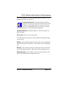
There are a number of Image focussing options available to you
through the Fringe set up screen:
Contrast reference. Selecting Contrast reference
makes it easier for you to pick out surface detail. It also
produces a ‘ghost image’ that you can use to line up
successive components when you require to measure
the same point on a series of identical components.
Gradient enhance. Gradient enhance is useful to help you to
pick out edges.
Cross hair. Turn on a cross hair cursor.
The following scan options are also available through the Fringe
set up screen:
Range. This window defines the range of the scan as defined by
the top and bottom limit markers. This figure can be changed by
you.
Bottom. This window defines the end point of the scan defined
by the bottom limit marker. This figure can be changed by you.
Estimated time. This window gives the estimated time it will
take for the instrument to complete the scan.
Issue 5.2 September 2005
Page 4-11
TS CCI 3D Non-Contact Surface Profiler Systems
Scan setting buttons. These buttons
found on the Fringe Set up tab enable you
to set a position on the piezo/scan range as
the:
•
Top of the scan
•
Set piezo to centre of range
•
Bottom of the scan
The slider. The slider shows the extent of
the scan as defined by the scan setting buttons. The top line is the top limit marker
and is defined by clicking on the Top of the
scan button, whilst the bottom line is the
bottom limit marker and is defined by
clicking on the Bottom of the scan button.
The lighter areas at the top and bottom of the range represent the
run-up and run-down sections of the measurement.
IMPORTANT. For the measurement to capture all of the data, all
of the fringes have to appear between the top and bottom limit
markers.
Light Level Setting. Not available on this version of the CCI.
Page 4-12
Issue 5.2 September 2005
TS CCI 3D Non-Contact Surface Profiler Systems
Measurement screen
The measurement screen is accessed through the measurement tab
and gives you the functionality for defining a measurement, saving
the results and beginning the TalyMap program. The options
given on the screen are:
Computation settings. Two selections are provided giving
you the option of selecting:
•
Post Process. If 'post' is selected the computer waits for the
scan to complete, then the data from the camera is processed.
Using post processing can decrease the number of missing data
points, especially on low reflective surfaces.
•
Peak Only. Coatings on a sample or rough surfaces can confuse the algorithm, in these cases use ‘peak only’ setting. This
option can be changed before or after a measurement.
Issue 5.2 September 2005
Page 4-13
TS CCI 3D Non-Contact Surface Profiler Systems
Settings. The settings options available are concerned with how
the data from a measurement is saved and passed to the TalyMap
analysis software.
•
Save 3D Data File As. The user is able to enter into the given
box, the filename of the .sur file that is to be assigned to the 3D
data when it is saved.
•
Auto-increment. If the box is ticked then subsequent measurements will be stored with the same filename, the software will
add a three digit extension to the filename, eg
TalysurfCCI001.sur, TalysurfCCI002.sur, and so on.
•
New document. If the box is ticked then each measurement is
placed in a new Talymap document. Other wise measurements
are appended to a new document.
•
Apply template to document. There is also a tick box under
this option that allows you to tell TalyMap to apply a particular
template to the document, there is an associated box to allow
you to enter a known template name, or an ellipsis [...] to allow
you to select a stored template. If the template acts on a single
measurement, select New document also.
•
Auto-run TalyMap. With this tick box set the TalyMap analysis package is started at the end of the measurement sequence
and the data collected from the scan is transferred to TalyMap.
Show TalyMap button. The user is able to switch to the
TalyMap 3D analysis package from within the CCI software, if required by clicking the Show TalyMap button.
Measure.
Start Measurement button. Clicking this button will
start the process of making the measurement. The
progress of the Scan and the subsequent Correlations
Page 4-14
Issue 5.2 September 2005
TS CCI 3D Non-Contact Surface Profiler Systems
process is given by means of a progress bar on the measurement
macro dialog. The time remaining in seconds is displayed. There
are two measurement macro dialogs, ie single and multiple, as
shown. The multiple measurements option creates an ‘average’
measurement from 2, 4, 8 or 16 measurements.
Measurement Type. Can be set to HDD Slider for Hard disk
Drive slider measurements.
Stop Measurement button. Clicking on this button will
prematurely stop the measurement process and the
measurement data is discarded. To restart the scan the
Start Measurement button is pressed, however the scan
restarts from its start position, not the position that was reached at
the point when the Stop measurement button was pressed
Frame sequence. The frame sequence is the series of video
frames seen when going from the top to the bottom of the piezo/
scan range. It is for diagnostic use only. There are three buttons in
this area:
Save Frame sequence.
This button enables
you to save a
sequence of frames.
Issue 5.2 September 2005
Page 4-15
TS CCI 3D Non-Contact Surface Profiler Systems
The user gives the sequence a filename and the file is saved as a
.fgb file.
•
Load frame sequence. This button enables you to load frame
sequence files (.fgb) from memory.
•
Show Frame Sequence. This button enables you to view the
frame sequence through the video screen.
Axis Control Screen
At start up the user is prompted to optionally home the axes. This
will set the axes to pre-defined positions by moving each axis to its
end stop as described on the homing dialog. This homing prompt
can be turned off from the dialog. It is turned on again from the
menu "Tools > Options".
Move To Position.
Page 4-16
Issue 5.2 September 2005
TS CCI 3D Non-Contact Surface Profiler Systems
•
Specify a position for one or more of the axes and select "Go"
to start the move.
•
Select the home button to move all axes to their home positions.
Z Move. Select and hold the arrowed button to move the Z axis at
a slow speed in the direction of the arrow. This speed is suitable
for focussing and finding fringes.
Step/Nudge Move. Enter a step increment for X/Y or for Z and
then press the appropriate button to move the X, Y or Z axis in the
required direction. A single press of the button will move the axis
the increment specified. If you hold the button then the axis will
continually increment until the button is released.
Refresh Joystick. This button can be used to re-enable the joystick.
Load Component. Select this button to start a load component
sequence. A dialog is displayed where one or more axes positions
can be entered. Select "Go" to start moving the axes to the specified positions. When the axes have stopped moving you can load
your next component. Select "OK" when prompted to return the
axes back to their original positions.
Z Bottom End Stop. The Z axis has a bottom end stop which
can be set. You will typically need to set this just above the component surface so that the Z axis cannot be driven down to the
component where it would damage the instrument and the component. Move the Z axis down so that the lens is just above the component surface and then select the "Set Z Bottom End Stop at
Current Position" button. When the end stop is set the red highlighting is removed and the status bar will display the Z Stop
value. To clear the Z Stop select the button "Clear Z Bottom End
Stop". Additionally the Z Bottom end stop can be set to a preIssue 5.2 September 2005
Page 4-17
TS CCI 3D Non-Contact Surface Profiler Systems
determined value using the button "Set Z Bottom End Stop to
value".
Toolbar
Calibrate button. The Calibrate button initiates the
instrument calibration process. The calibration process
uses a self descriptive wizard and requires calibration
artefacts to be available during the process. Only available to Admin/Service users.
Diagnostics button. The Diagnostics button initiates the instrument’s diagnostic process to enable you
to determine whether the instrument is currently functioning correctly and to determine where the faults (if
any) are located. Only available to Admin/Service
users.
Measure button. The Measure button begins the
measurement process.
Help button. The Help button takes you into the
Help System. This gives you help with using the
instrument in the form of ‘How Do I’ instructions.
The glossary of terms is also provided to assist in the
operation of the instrument.
Stop button. The stop button is used to stop all axes
moves.
Page 4-18
Issue 5.2 September 2005
TS CCI 3D Non-Contact Surface Profiler Systems
Start a pattern measurement. Only available if
automated axies are connected. See Page 4-57 for
further details.
Start a HDD Slider measurement. Only available if a HDD licence is installed. See page 4-61 for
further details.
Issue 5.2 September 2005
Page 4-19
TS CCI 3D Non-Contact Surface Profiler Systems
Main menus
File menu. The File menu provides you with the means to open
the measurement setting for you to amend or execute, or to save
the measurement. Program exit is also provided on the File menu.
Actions menu. The Actions menu provides options that reflect
the toolbar functionality, eg Calibrate, Diagnostics and Measure.
Selecting one of these options in the menu will invoke the appropriate function in the same way that the Calibrate, Diagnostics and
Measure buttons do on the main toolbar.
User. The User menu enables the different levels of User ie Standard User, Admin User and Service User to log into the system
and gain access to their appropriate level of privilege. Both
Admin User and Service User are requested to input the appropriate password.
Both Admin and Service Users can if required change their password, see How Do I Change My Password, page 4-20.
Tools. The Tools menu enables you to select the units of measurment. The default setting for the units of measurement is the metric system. It also allows you to select Macros, where you can run
and optionally create and edit macros to control the measurement.
For automated systems the homing prompt at start up can be
turned on.
If a licence exists for HDD Slider Measurement this menu also
includes a button for launching an application to create and edit
slider definition files (See section 'HDD Slider Measurement' on
page 4-61).
Macros are written in Visual Basic for .NET using Microsoft’s
Visual Studio for Applications (VSA)©.
Page 4-20
Issue 5.2 September 2005
TS CCI 3D Non-Contact Surface Profiler Systems
An example measurement macro is provided. VSA includes
online help for writing Visual Basic macros and macros can only
be created/edited by an Admin user.
Help. Access to On-line help and to licensing information
Issue 5.2 September 2005
Page 4-21
TS CCI 3D Non-Contact Surface Profiler Systems
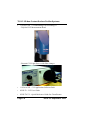
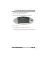
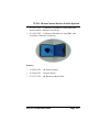
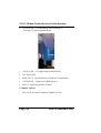
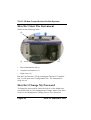
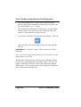
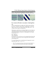
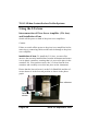
How Do I Start The Instrument
Switch on the following items:
(3)
(1)
•
Power Distribution unit (1)
•
Computer and monitor (2)
•
Light source (3)
(2)
Run the User Interface (UI) by running the Talysurf CCI application. It will open in the Configuration Tab. The instrument is
ready for use.
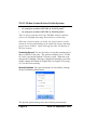
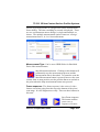
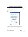
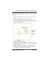
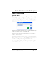
How Do I Change My Password
To change the password for either the Service or the Admin user
you should click on User Management>Change Admin User Password or User Management>Change Service User Password.
Page 4-22
Issue 5.2 September 2005
TS CCI 3D Non-Contact Surface Profiler Systems
The Change Password dialog
appears:
Enter the existing password in
the box titled Old Password
and then enter the new password into the box titled New
Password and confirm this by
re-entering in the Confirm New Password box. Click on OK to
confirm.
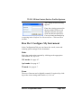
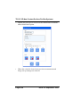
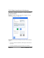
How Do I Configure My Instrument
In the Configuration Tab you can choose the mode, zoom and
scanning speed settings for the instrument.
Mode
Select the mode option required by clicking on the appropriate
radio button, XY, xyz or Z
‘XY’ mode. See page 4-7.
'xyz' mode. See page 4-7.
'Z' mode. See page 4-7.
Zoom
The area of interest can be digitally zoomed, if required, by clicking on the zoom setting radio button x1, x2 or x4.
Issue 5.2 September 2005
Page 4-23
TS CCI 3D Non-Contact Surface Profiler Systems
Please note that only certain combinations of zooming and mode
are allowed, as shown in Table 4-1.
Table 4-1: Zoom and Binning Combinations
Zoom
Mode
XY
xyz
Z
x1
X
X
X
x2
X
X
x4
X
Scanning Speeds
Select the scanning speed required for the measurement by clicking on the scanning speed radio button x1, x5 or x9.
The 1x speed produces the most accurate results, but achieves this
at the expense of measuring speed. The x5 and x9 speeds increase
measurement speeds whilst sacrificing accuracy. The x5 and x9
speeds are most appropriate when the ultimate accuracy is not
required, that is when measuring rough surfaces.
When the scanning speed is changed a message is displayed
informing you of the need to change the Hardware Light Filter
(see Light Levels, page 4-37) is set to the same setting as the scanning speed.
Special options
Select any of the Special Options as required, see page 4-48.
Page 4-24
Issue 5.2 September 2005
TS CCI 3D Non-Contact Surface Profiler Systems
How Do I Calibrate My Instrument
The calibration of the instrument is performed using one of the
three calibration artefacts and utilises the software calibration wizard.
Calibration Types
•
XY Calibration (X and Y Gains)
•
Z Calibration (Z Gain)
•
Z Datum Correction (Z Form from a single measurement)
•
Advanced Z Datum Correction (Z Form from multiple measurements)
Calibration Wizard
•
You access the software calibration wizard through either the
Actions menu, see page 4-19 or the button on the toolbar.
•
When the wizard is opened a live video image is displayed in
the main image window.
•
The wizard contains a front page displaying the current lens
and each of the calibration types. Selection of one of these
options + "next" leads to one or more pages of information
relating to that calibration type. Additionally there is an
Issue 5.2 September 2005
Page 4-25
TS CCI 3D Non-Contact Surface Profiler Systems
option, one per type, to reset all of the calibrations to defaults
and a finish/close option.
•
When the wizard is closed your previous measurement and
fringe set-up settings are restored.
Page 4-26
Issue 5.2 September 2005
TS CCI 3D Non-Contact Surface Profiler Systems
XY Calibration (X and Y Gains)
Artefact. Glass target with concentric circles is provided as an
accessory, see page 4-34.
Sequence. You access "XY Calibration" from calibration wizard.
•
Set up the calibration standard by following the instructions in
the wizard.
•
To start the calibration you need to click on "Go" button.
Issue 5.2 September 2005
Page 4-27
TS CCI 3D Non-Contact Surface Profiler Systems
•
The wizard displays the "Current Error" as the difference
between the measured diameter (using the previous gain) and
the actual diameter (e.g. 0.15µm).
•
You decide if the calibration is ok and select "Accept" button
on the wizard. The wizard stores the calibration value (XY
Gain) to a file against the current lens type.
•
To repeat the calibration, click on the camera button. This will
return you to the live video image so that you can repeat the
process.
Application. CCI applies X and Y Gain correction to all measurements.
Note. CCI will not apply X and Y Gain correction to the live video
image display or its scale.
The diameter of the concentric circles on the calibration artefact
are stored in a configuration file as default values. The user can
supply an alternative diameter value in the calibration standard
diameter box - if for example a more accurate figure was obtained
from a different measuring device.
Page 4-28
Issue 5.2 September 2005
TS CCI 3D Non-Contact Surface Profiler Systems
Z Calibration (Z Gain)
Artefact. 3 Line step height. TH offer two line step heights for
the CCI instrument. One has a nominal step of 5µm and the other
a step of 50µm You decide which to have depending on measurement range or lens type. You can also use your own standard.
If using the 50µm Step Height see page 4.29.
Sequence. User accesses "Z Calibration" from calibration wizard.
Issue 5.2 September 2005
Page 4-29
TS CCI 3D Non-Contact Surface Profiler Systems
•
Set up the calibration standard by following the instructions in
the wizard.
•
You can optionally modify a displayed actual step height
value.
•
To start the calibration you need to click on "Go" button.
•
The wizard causes a measurement to be taken and step height
to be calculated in TalyMap. A new gain is calculated.
•
Alternatively you can enter the result for the calculated step
height value and select the confirmation button.
•
The wizard displays the "Current Error" as a difference
between the measured step height (using previous gain) and
the actual step height (e.g. 0.15µm).
•
You decide if calibration is ok and select the "Accept" button
on the wizard to cause wizard to store the calibration value (Z
Gain) to a file against the current lens type.
•
The CCI application applies the Z Gain correction to all measurements.
•
To repeat the calibration, click on the camera button. This will
return you to the live video image so that you can repeat the
process.
Page 4-30
Issue 5.2 September 2005
TS CCI 3D Non-Contact Surface Profiler Systems
50µm step height procedure. Measure the 50µm Step Height
and enter the measured value into Calibration wizard by doing the
following:
1. Run the Calibration Wizard and clear any existing Z Calibration.
2. In the Configuration Tab select 'Z' Mode, Zoom x1.
3. Ensure component is level, scan range is approx 60µm so that
fringes occur on the top and bottom surfaces. Ensure the measuring line is in the centre.
4. Measure the levelled step height.
5. In Talymap, Zoom the required profile, Convert into a series of
profiles and generate a mean profile. Analyse the step height
of the mean profile.
6. Run the Calibration Wizard and select Calibration type Z.
7. Enter the calculated step height from Talymap into the "Measured Height" box and select "Accept" button.
Issue 5.2 September 2005
Page 4-31
TS CCI 3D Non-Contact Surface Profiler Systems
Advanced Z Datum Correction (Z Form from multiple measurements)
Artefact. Circular coated glass mirror flat; Lambda / 50 is provided as an accessory, see page 4-34.
Sequence. User accesses "Z Datum Correction" from calibration
wizard.
•
Set up the calibration standard by following the instructions in
the wizard.
•
To start the calibration you need to click on "Go" button.
Page 4-32
Issue 5.2 September 2005
TS CCI 3D Non-Contact Surface Profiler Systems
•
The wizard causes a measurement to be taken and processed
for form with the resultant surface being displayed.
Note: form processing involves levelling and filtering.
•
You decide if the surface is ok and select "Add" to cause the
surface to be added to the mean surface. The mean surface is
then displayed and the wizard calculates "RMS" of the current
surface (after software levelling and filtering) with current
"mean surface" removed, i.e. datum corrected. The "RMS"
value is displayed.
Note: You may choose to ignore the surface by not selecting
"Add".
•
Rotate and move the part.
•
You then need to click on "Go" button, repeating until a pre-set
number of acceptable measurements have been taken.
•
The wizard calculates "RMS" of the current surface with the
new "mean surface" and "RMS" of the current surface with the
previous calibration's mean surface.
•
The wizard displays the "Current Error" as the difference
between RMS_new and RMS_previous (e.g. 0.85nm).
•
You select "Accept" button on the wizard to store the calibration value against the current lens type.
•
The CCI Application applies the Z Form correction to all measurements.
Issue 5.2 September 2005
Page 4-33
TS CCI 3D Non-Contact Surface Profiler Systems
Z Datum Correction (Z Form from a single measurement)
Artefact. As for Advanced Z Datum Correction.
Sequence. Similar to that for multiple measurement Z Datum
Correction except only one measurement is taken.
Application. As for Advanced Z Datum Correction.
Note: Only a single Z datum correction surface is to be maintained
which is set either via the normal or advanced datum correction
methods.
Calibration Artefacts
Available calibration artefacts for the instrument are the Step
Height Calibration Standard, see figure 4-1 and 4-2, the Lateral
Calibration Standard, see figure 4-3 and the Calibration flat, see
figure 4-4. The Step Height Calibration Standard is used to calibrate the Z gain. The Lateral Calibration Standard consists of a
number of concentric circles used to calibrate the XY gain.
The calibration artefacts available as accessories for the instrument are:
•
Step height calibration standard 5µm with traceable calibration.
•
Step height calibration standard 50µm with traceable calibration.
•
Lateral calibration standard.
•
Lateral calibration standard with traceable calibration.
•
Precision flat.
Page 4-34
Issue 5.2 September 2005
TS CCI 3D Non-Contact Surface Profiler Systems
•
Precision flat with traceable calibration
Figure 4-1 Step Height Calibration Standard 5µm with traceable
calibration
Three lines are etched onto the surface, the centre one being the
calibrated line.
Figure 4-2 Step Height Calibration Standard 50µm with traceable
calibration
Issue 5.2 September 2005
Page 4-35
TS CCI 3D Non-Contact Surface Profiler Systems
Figure 4-3 Lateral Calibration Standard with or without traceable
calibration
There is an additional calibration artefact available, the Calibration
Flat, that is used to calibrate and quantify the form error of the system.
Figure 4-4 Calibration Flat with or without traceable calibration
Page 4-36
Issue 5.2 September 2005
TS CCI 3D Non-Contact Surface Profiler Systems
How Do I Make a basic Measurement
The steps to making a basic measurement are as follows:
•
Select a lens
•
Change the lens (if required)
•
Position the component
•
Configure the instrument
•
Focus on Surface, Set Light Levels and Find Fringes
•
Set Scan Length and start position
•
Set up TalyMap
•
Make a scan
•
Analyse the results
Selecting a lens
The choice of objective lens depends on:
•
how large an area you want to measure,
•
the lateral detail you want to be able to resolve.
A 10x objective proves ideal if you need a medium field of view,
but the 50x objective is more suitable if you need greater x/y
resolving power or need to examine features that have high slope
gradients.
Note. The vertical resolution of the instrument does not depend on
the objective lens.
The higher magnification objectives are able to measure steeper
inclines. This makes them more suitable for measuring extremely
Issue 5.2 September 2005
Page 4-37
TS CCI 3D Non-Contact Surface Profiler Systems
rough surfaces and more undulating components than the lower
magnification objectives, see Table 2-1 on page 2-3.
Changing lens. To change the lens, you must first unscrew the
current lens from the instrument and return it to its plastic container, ensuring that it is screwed in place in the container lid. You
can then remove the new lens you require from the lens container
and screw this onto the instrument.
There is a quick release fitting that enables the lens to be changed
quickly and easily.
Caution.
Great care must be taken not to touch the optical faces of the lens
and to not drop the lens during removal and fitting.
After you have changed the lens, ensure that the correct objective
lens is selected at the top of the Configuration Tab of the UI.
Positioning the component
Place the component to be measured onto the measuring table top
and roughly locate the region of interest beneath the objective lens.
On a textured surface you will be able to see a light spot on the
area.
Configure the Instrument
See How Do I Configure My Instrument, see page 4-21.
Page 4-38
Issue 5.2 September 2005
TS CCI 3D Non-Contact Surface Profiler Systems
Focus on Surface, Set Light Levels and Find Fringes
The following quick procedure will focus on the surface, set
appropriate light levels and find the required fringes. A more
advanced procedure is given in Advanced topics, see page 4-43.
•
Select the live video tab on the UI.
•
Ensure x1 zoom is selected in the Configuration Tab of the UI.
•
Use the Z adjust to move the measuring head closer to the
component than the objective lens' working distance (see Table
2-1 on page 2-3).
OR
Z Control, one
each side
Caution.
When the objective lens is close to the surface of the component,
take care not to impact the objective or the PZT body into the comIssue 5.2 September 2005
Page 4-39
TS CCI 3D Non-Contact Surface Profiler Systems
ponent as this may damage the objective or the PZT scanner.
THIS IS NOT COVERED BY WARRANTY. There is a piezo
buzzer that warns of contact of the objective with the component.
•
Turn on the light source.
•
Set the light level using the light level control so that a small
yellow area can be seen on the image. Use the Z adjust to raise
the measuring head. The size of the yellow area will increase
to a maximum, as will the light level display. At this point you
are close to the fringes.
•
Reduce the light level so that no yellow areas are present, light
level is approximately 50 on light meter with no fringes visi-
Page 4-40
Issue 5.2 September 2005
TS CCI 3D Non-Contact Surface Profiler Systems
ble. This method is particularly effective with the 50x objective. Use the Z adjust to slowly move the component in Z until
the fringes appear.
•If at any point you see an image similar to
that shown, use the Z adjust to bring the component closer to the objective lens. The
image is part of the instrument's optical system that has come into focus. This image is
very close to the fringes with the 50x objective but gets further away the larger the objective.
Set Scan Length and position
Scan setting buttons. These buttons
found on the Fringe Set up tab enable you to
set a position on the piezo/scan range as the:
•
Top of the scan
•
Set piezo to centre of range
•
Bottom of the scan
Issue 5.2 September 2005
Page 4-41
TS CCI 3D Non-Contact Surface Profiler Systems
The slider. The slider shows the extent of the scan as defined by
the scan setting buttons. The top line is the top limit marker and is
defined by clicking on the Top of the scan button, whilst the bottom line is the bottom limit marker and is defined by clicking on
the Bottom of the scan button.
The lighter areas at the top and bottom of the range represent the
run-up and run-down sections of the measurement.
IMPORTANT. For the measurement to capture all of the data, all
of the fringes have to appear between the top and bottom limit
markers.
Turn off any focussing aids (Contrast reference, Gradient enhance
and Focus filter) and use the slider to move the fringes around to
check the light level. Adjust the light level so that no yellow areas
are visible. Yellow areas show that there is too much light. If a
pixel is saturated at any point during a measurement it will turn
into missing data.
Setting TalyMap options
There are a number of options that you can set that will affect the
way that TalyMap acts on the data measured.
Save 3D Data File As: Enter the filename that you wish CCI to
save the measured data file under.
Page 4-42
Issue 5.2 September 2005
TS CCI 3D Non-Contact Surface Profiler Systems
Auto-increment. If the box is ticked then subsequent measurements can be stored with the same filename, the software will add
a three digit extension to the filename, eg TalysurfCCI001.sur,
TalysurfCCI002.sur, and so on.
New document. Select this tickbox if you wish TalyMap to
start with a new document when it analyses the measured data.
Apply template to document. Select the template that you
wish TalyMap to apply to the analysed data. Click on the ellipsis
[...] to browse the available templates. If the template operates on
a single measurement, select the new document option also.
Auto run TalyMap. Select this tickbox if you wish TalyMap to
automatically start once the measurement is complete.
Show TalyMap button. Click on this button to start the TalyMap program manually.
Making a Scan
To make a scan, click the go button in the Measurement Tab, a new
dialogue appears detailing progress and providing you with a Stop
button. You cannot move around the UI while a measurement is
taking place. The only button you can press is the red stop button.
If desired the component can be moved once the 'scan' progress
bar is complete.
Basic Analysis
Once the measurement is complete the 'Surface' pane will show
the result. The shape of the surface is suggested by a 'bluescale'
image, where lower areas appear darker than higher areas. Any
red spots are missing data.
Issue 5.2 September 2005
Page 4-43
TS CCI 3D Non-Contact Surface Profiler Systems
The analysis of the results is performed using TalyMap. Please
refer to the TalyMap system for Operating Instructions.
To start the TalyMap program click on the Show TalyMap button.
Note. After the surface has been displayed for a short while, the
live video pane is automatically redisplayed
Calibration
Note. you should calibrate the instrument regularly and monitor
the calibration constants to enable you to monitor the effects of
the environment and time on the stability of the instrument and
the measurements made.
See How Do I Calibrate the instrument, page 4-23.
Page 4-44
Issue 5.2 September 2005
TS CCI 3D Non-Contact Surface Profiler Systems
Advanced Measurement Topics
Technical Description of Scanning Broadband Interferometry
An interferometer is an optical device that splits a beam of light
from a single source into two separate beams. Each of these beams
travel separate paths, one onto a reference surface and the other
onto the surface to be measured. The beams are then recombined
resulting in an interference pattern. An imaging device, usually a
CCD array, is used to collect this information.
In a scanning broadband interferometer a white light source is
used, this has the effect that interference reaches maximum intensity when the two paths, one to the reference and the other to the
sample surface, are the same distance. By moving the interferometer vertically away from the measurement surface the point at
which this interference occurs can be found for each pixel of the
CCD. By tracking the position of the interferometer during this
process a 3D map of the surface can be formed.
Figure 4-2 Interferometer Schematic
Issue 5.2 September 2005
Page 4-45
TS CCI 3D Non-Contact Surface Profiler Systems
Sample Preparation for Measurement
Samples for measurement must be clean and free from grease,
smears, fingerprints and dust. Handling procedures must ensure
that the sample is not contaminated with any of these. No other
preparation for the sample is necessary.
•
If there are fingerprints/smears on the sample the instrument
will measure them, rather than the sample itself.
•
Bits of dust and dirt on the sample could end up as missing
data.
Good Metrology Practice for CCI
As mentioned in Chapter 3, the following areas will affect the
quality of the measurements made:
•
Locating the instrument in a clean area to minimise airborne
particles, ie smoke, dust and airborne oil particles.
•
Draughts and airborne vibration should be avoided.
•
Temperature Gradients, areas that experience temperature gradients of over 2°C/hour are not ideal for the measurement of
precise form.
•
Vibration is particularly detrimental for the measurement of
surface texture. Sources of vibration should be removed
•
It is important that a clean power supply should be provided to
the instrument.
Page 4-46
Issue 5.2 September 2005
TS CCI 3D Non-Contact Surface Profiler Systems
Finding Fringes and Use of Levelling Stages
Finding fringes. The following procedure defines the process
for finding fringes for the two specific cases you may come across,
ie a surface with defined features, or a featureless surface where
the image focussing is used to assist the process:
•
Turn on the light source.
•
Ensure x1 zoom is selected in the Configuration Tab of the UI.
•
Use the Z adjust to move the measuring head closer to the
component than the objective lens' working distance (see Table
2-1 on page 2-3) given on the side of the objective lens
•
Select xyz mode and ensure that the Data Out Mode > Low
Noise is not selected on the Special options dialog. This
reduces the camera exposure time that improves visibility of
fringes when the Z axis is moving.
If the component is machined metal/rough (non-ceramic)/etched/
MEMS…
•
Set the light level so that no yellow areas are visible. The
video panel should show a pale blue colour.
•
With no fringes visible, a light value of 50 on the light meter
will give best results
•
Use the Z adjust to bring the part into focus and interference
fringes should become visible.
•
Also turn on the gradient enhance.
If the component is smooth and featureless…
•
Set light level so that no yellow areas can be seen, with no
fringes visible, a light value of 50 on the light meter will give
best results. The monitor should show a pale blue colour.
Issue 5.2 September 2005
Page 4-47
TS CCI 3D Non-Contact Surface Profiler Systems
•
In the configuration tab, set mode to xyz and scanning speed to
x9, also adjust the filter on the light box to III.
•
Select the Fringe Setup tab of the UI. If no features are visible
click the contrast reference button and turn the contrast reference option on.
•
Move the Z adjust to raise the measuring head until a surface
comes into focus.
•
Use the Z adjust to find the fringes.
•
Set the mode, scanning speed and filter back to the required
values.
•
Turn off the focus aids and ensure there are no saturated (yellow) areas.
Levelling a component. The interference fringes that you see
on the video screen of the software are a certain vertical distance
apart. Therefore the more fringes you see or the closer the fringes
are together, the less level the component is.
If you spend a little time levelling a component well, the measurement time can be reduced significantly, as the instrument does not
have to scan as far as it would with an unlevelled component. The
end result is also slightly better, although it should be noted that
the difference created by a shallow slope is very slight.
If necessary use the focussing aids on the Fringe Setup Tab to
make the fringes more obvious. Rotating a knob on the tip-tilt
stage clockwise causes the fringes to rotate anticlockwise and vice
versa.
To level the component you need to rotate the right-hand knob on
the tip-tilt stage until the fringes spread out and cross the screen at
45°. While doing this use the Z adjust to keep the fringes on the
Page 4-48
Issue 5.2 September 2005
TS CCI 3D Non-Contact Surface Profiler Systems
screen. Then rotate the left-hand knob, causing the fringes to
spread out further until a single fringe can be seen on the screen.
Pre-Analysis of Results, Assessment of missing Data
etc.
Once the measurement is complete the 'Surface' pane will show
the result. The shape of the surface is suggested by a 'bluescale'
image, where lower areas appear darker than higher areas. Any
red spots on the image are missing data.
Missing data could be due to having the light level set too high, try
reducing the light level and re-performing the measurement, the
missing data should be reduced, see setting light levels information on pages 4-37.
Data Binning
Data Binning refers to the process of averaging the data from adjacent pixels, averaged to give one average pixel selected from the
surrounding pixels.
To set the binning level you should select the appropriate resolution mode, that is ‘XY’, ‘xyz’ or ‘Z’.
•
The 'XY' resolution mode gives the greatest lateral detail. It
looks at all 1024x1024 pixels of the camera individually,
Issue 5.2 September 2005
Page 4-49
TS CCI 3D Non-Contact Surface Profiler Systems
resulting in a longer calculation time. This mode would, for
example, be used when measuring a finely polished sample.
•
The 'xyz' mode applies 2x binning. This means that a square
of 2x2 pixels is averaged to create one, bigger, average pixel.
This results in better Z resolution, but you loose out on some
x-y detail.
•
The 'Z' mode applies 4x binning; a square of 4x4 pixels is
combined into one. This gives the best result in Z, although
more x-y detail is lost. Z mode would, for example, be used
for measuring step heights.
Camera binning decreases the scan time, but software binning
decreases the system noise.
How do I use the Special Options
To access the Special options, click on the Exclamation mark button in the Configuration Screen.
The Special options dialog offers the following functionality:
Note. For details of what each option does and the disadvantages
of each, see page 4-8.
Data Output Mode (Low Noise).
This consists of a tick box to select Low noise, which uses software binning, the default condition is with the tick box unselected.
When to use it: When the very lowest level of measurement noise
is required, less than 5nm. How to use it: Select either ‘xyz’ or ‘Z’
mode, depending on lateral detail required, select ‘Low Noise’.
Page 4-50
Issue 5.2 September 2005
TS CCI 3D Non-Contact Surface Profiler Systems
Scan Type.
The options are Top Surface selected and Top Surface unselected
(Standard). When to use it: Use it to automatically measure top
surface only on samples with more than one reflective layer. How
to use it: Select ‘Top Surface’.
Post Threshold.
This consists of a slider that goes from min to max (default).
When to use it: Use to reduce the amount of missing data caused
by low surface reflectivity. How to use it: Select ‘Post’ on the
‘Measurement’ tab. Select a lower Post Threshold to allow the
system to measure lower reflectivity surfaces.
Issue 5.2 September 2005
Page 4-51
TS CCI 3D Non-Contact Surface Profiler Systems
Basic TalyMap Functionality
For full operational details consult the TalyMap documentation
Page 4-52
Issue 5.2 September 2005
TS CCI 3D Non-Contact Surface Profiler Systems
Issue 5.2 September 2005
Page 4-53
TS CCI 3D Non-Contact Surface Profiler Systems
Using the 2.5x lens
Interconnection of Piezo Servo Amplifier (2.5x lens)
and Installation of lens
Switch off the power to both of the piezo/servo amplifiers.
Caution.
Failure to switch off the power to the piezo/servo amplifiers before
removing or connecting cables could result in damage to the piezo/
servo amplifier.
Installation of lens. To install the 2.5x lens, you must first
unscrew the currently installed lens from the instrument and return
it to its plastic container, ensuring that it is screwed in place in the
container lid. You can then remove the 2.5x lens from the lens
container and carefully screw this into place on the instrument.
Ensure that the lens reference is at the Left Hand Side and the reference shutter is in the forward position as shown in the photograph.
Lens reference
Reference
shutter
Page 4-54
Issue 5.2 September 2005
TS CCI 3D Non-Contact Surface Profiler Systems
Caution.
Great care must be taken not to touch the optical faces of the lens
and to not drop the lens during removal and fitting.
Remove the power lead, the three Lemo coaxial connectors and
one D type connector from the standard Piezo Servo Amplifier and
connect to the Piezo Servo Amplifier specially configured for the
2.5x lens, see photograph and interconnection diagram.
Switch on the power to the piezo/servo amplifiers.
Issue 5.2 September 2005
Page 4-55
TS CCI 3D Non-Contact Surface Profiler Systems
Using the lens. After you have changed the lens, ensure that the
correct objective lens is selected at the top of the Configuration
Tab of the UI. The following procedure needs to be used to perform the Z Calibration (see also page 4.27 of User’s Guide):
Measure the levelled step height using zoom magnification of x2.
In Talymap apply the template "StepHeight.MNT" which will
determine the step height value.
Run the Calibration Wizard and select calibration type Z.
Enter the calculated step height from Talymap into the "Measured
Height" box and select the "Accept" button.
After taking a measurement TalyMap can be used to zoom to the
required field of view. An example TalyMap template is available
named ZoomFor2.5xLens.mnt and this can be specified in the UI’s
Measurement tab.
Page 4-56
Issue 5.2 September 2005
TS CCI 3D Non-Contact Surface Profiler Systems
Patern measurement
Pattern Control
The pattern is controlled via a pattern file, described later, which
includes X Pitch, Y pitch, X measurements, Y measurement. The
user may select which pattern file to use via a dialog shown below,
at the start of the pattern measurement. The selected file will be
checked to ensure it is valid and any errors reported.
Alignment information consisting of up to 2 points (defined in grid
relative co-ordinates) is also stored in this file.
Alignment point indices are based on an index of 1 (instead of
standard zero based index).
Automatic positional correction / tracking is available for X, Y &
Z axes and can be turned on or off via the 'XYCorrectionRequired'
and 'ZCorrectionRequired' settings in the definition file.
An example file is available, PatternExample.txt (in the Application's installation folder).
Issue 5.2 September 2005
Page 4-57
TS CCI 3D Non-Contact Surface Profiler Systems
Pattern Execution
During pattern execution live video is displayed (no surface
images).
Alignment dialog displayed if necessary asking the user to move
to / confirm position of 1st (and 2nd if required) alignment point as
defined in pattern file. This only appears if "AlignmentRequired"
is set to 'true' in pattern file.
A Progress dialog is displayed during a pattern measurement to
indicate pattern site and total sites.
Movement. A raster movement is performed across all sites.
First site is current position. On completion the system moves
back to the first position. Movement order is along increasing X,
move to next Y and return to start of X, etc.
Measurement/Analysis. This is done at each site using current
measurement and Talymap settings. If Talymap parameters are
calculated then an export of Talymap data is done and concatenated into a file, "PatternResults.txt", overwriting the existing file.
If the user stops the pattern or an error occurs then the user is
prompted for "Repeat the measurement", "Go to next measurement" and "Abort".
Page 4-58
Issue 5.2 September 2005
TS CCI 3D Non-Contact Surface Profiler Systems
At the end of the pattern the axes and piezo are returned to their
starting positions.
Pattern File
The pattern file consists of the following entries:
Line
Comments
[GridPatternSettings]
Section Header for measurement
positions
X Pitch MM=0.01
Distance between X positions (mm)
0 and above.
Y Pitch MM=0.01
Distance between Y positions (mm):
0 and above.
X Total=3
Number of X positions: 1 or more.
Y Total=3
Number of Y positions: 1 or more.
MeasureAllPointsInGrid
=True
Set to "True" to measure all points in
a grid. False is not yet supported.
[Alignment]
Section Header for alignment
information
AlignmentRequired=False
"True" if alignment points are to
be used.
Number of Alignment
Points =2
Number of alignment points to be
used 0,1 (X1,Y1)
or 2 (X1,Y1 and X2,Y2)
Issue 5.2 September 2005
Page 4-59
TS CCI 3D Non-Contact Surface Profiler Systems
X1 Index=1
X Index of first alignment point,
typically 1: 1 to <X Total>.
Y1 Index=1
Y Index of first alignment point,
typically 1: 1 to <Y Total>.
X2 Index=2
X Index of second alignment point,
typically <X Total>: 1 to <X Total>.
0 if not required, Y2 must also be 0.
Y2 Index=1
Y Index of second alignment point,
typically <Y Total>: 1 to <Y Total>.
0 if not required, X2 must also be 0.
[AutoCorrection]
Section Header for auto correction
(tracking) information
XYCorrectionRequired
=False
ZCorrectionRequired
=False
Page 4-60
"True" if tracking in XY required.
Only valid for HDD measurements,
and uses HDD reference position to
align XY for next measurement.
"True" if tracking in Z required
(uses mean surface height and
adjusts the piezo position
for the next measurement).
Issue 5.2 September 2005
TS CCI 3D Non-Contact Surface Profiler Systems
Hdd Slider Measurement
The slider should be set up with fringes normal to the head as
shown below.
Actions menu and toolbar button to start a slider measurement.
Only available if licence is registered.
The HDD Slider information dialog contains fields for the user to
enter slider type, related information and results file name. The
user has the option to specify whether a single slider or a slider
holder is to be measured.
The slider type is specified as a file name. This file contains details
of each step to be measured on the slider. File details are provided
below.
The results file contains settings and results for each slider measured. A new file is created at the start of each slider holder measurement. File details are provided below.
After an HDD slider measurement the enhanced surface image
will be displayed.
After an HDD slider measurement selecting/deselecting the 'Peak'
radio will only display the enhanced SUR file output and not toggle between peak and phase results.
Issue 5.2 September 2005
Page 4-61
TS CCI 3D Non-Contact Surface Profiler Systems
Help menu contains licence item. Selection displays licence status
and option to enter a new licence that matches the unlock code of
the PC.
Slider measurement
This is carried out with the following measurement settings:
•
Mode: XY
•
Zoom: x2 (recommended)
•
Concurrent
•
Special options: Off
•
Slider Type definition file.
Slider Holder Control
The pattern feature is used to control the measurement of each
slider site on a slider holder. The pattern file is provided by the
user via the slider settings dialog.
The output from each slider measurement is appended to the
results file. Note: If it is a holder measurement then the existing
file will be deleted first.
Slider Definition Set-up
A graphical interface is provided via the Tools menu HDD Set-up
option to allow creation / editing of slider definition files. The system should be set up as it would for a slider measurement with a
sample slider in focus then run the HDD Set-up dialog. Follow the
instructions in the dialog to create or edit a settings file and then
use this settings file in the HDD Settings Form (See 'Hdd Slider
Measurement' section above).
Page 4-62
Issue 5.2 September 2005
TS CCI 3D Non-Contact Surface Profiler Systems
Slider File Format
An example slider file is shown below:
Line
Comments
[Coating Definition]
Section header for type of coating
DLC Coated = 1
Identifies if slider is DLC coated.
"1" =Coated, "0" = Not Coated
[Position Find Definition]
Section header for reference point
definition (see Note 2).
HorizFindOffset = 31
Distance up from horizontal
reference used to find
vertical reference line.
HorizFindLength = 100
Length of horizontal search centred
around vertical reference line.
[Normalisation Definition]
Section header for normalisation
area definition. (Should be AlTiC)
Width = 224
Height = 35
Left = -112
Top = -55
Position and area parameters
(see Note 1).
[Reference Definition]
Section header for reference area
definition. (Should be planarised
AlTiC)
CorrectFull = 0
Correction to full reference area,
used if the form of the
AlTiC area is to be measured.
Issue 5.2 September 2005
Page 4-63
TS CCI 3D Non-Contact Surface Profiler Systems
"1" = on, "0" = off.
Note: Step heights are always
calculated relative to the
defined reference region.
Width = 224
Height = 144
Left = -112
Top = 34
Position and area parameters
(see Note 1)
[Step 1 Definition]
definition
Name =S1
Section header for first step
Step identifier. This will appear in
the results file.
AlumOxide = 0
Identifies region step is in.
"1" = Aluminium Oxide region,
"0" = Magnetic Region
Width = 60
Height = 3
Left = -30
Top = 23
Position and area parameters
(see Note 1)
[Step 2 Definition]
Section header for second step
definition
Up to 10 'step' definitions may be
provided, use the following section
headers:
[Step 1 Definition]
[Step 2 Definition]
…
[Step 10 Definition]
Page 4-64
Issue 5.2 September 2005
TS CCI 3D Non-Contact Surface Profiler Systems
Note:
1.Position and area parameters
These parameters are provided in pixels. The image area is 256 x
256.
The 'left' and 'top' parameters are with respect to the reference
point. Note that the value is negative to the left of and above the
reference point.
2. Reference point definition
A search is made from the top to locate the rough position of the
magnetic area lower edge followed by a refined search at different
angles until the horizontal reference line is found. The X,Y reference point is then found by moving up a distance of HorizFindOffset normal to the reference line and searching along a profile of
length HorizFindLength until a defined landmark on the slider is
found.
An example slider image with rectangular areas is provided in the
following Figure.
Issue 5.2 September 2005
Page 4-65
TS CCI 3D Non-Contact Surface Profiler Systems
Slider Results File
An example results file is shown below.
All values are in mm.
For each 'step' defined in the definition file there will be a corresponding step height value and a roughness value (RMS) in the
results file.
Page 4-66
Issue 5.2 September 2005
TS CCI 3D Non-Contact Surface Profiler Systems
There is one row of results for each slider.
File
Name
C:\HD
D001.
SUR
Slider
Slider
Type
Batc
h ID
User
Info
Operator
S1
RMS
S1
Height
ALR
RMS
00 00
Typ1
A034
-
U1
2.87
E-06
1.29E
-05
6.31E06
ALR
Height
-2.1E05
Lenses
Objective
Lens
Field of View/mm
Working
Distance/mm
Lateral sampling
resolution/µm
Maximum
component slope/°
10x
1.26 x 1.26
7.4
1.2
+/- 8
20x
0.63 x 0.63
4.7
0.62
+/- 14.5
50x
0.25 x 0.25
3.4
0.25
+/- 22
Power lead
The power lead K509/1527 on the interconnection diagram on p.324 of the User Guide is replaced by K509/1539.
Issue 5.2 September 2005
Page 4-67
TS CCI 3D Non-Contact Surface Profiler Systems
Page 4-68
Issue 5.2 September 2005
TS CCI 3D Non-Contact Surface Profiler Systems
Chapter 5
Maintenance Procedures and Service
Support
Cleaning and Routine maintenance
General Cleaning
Caution:
Cleaning of the instrument using inappropriate cleaning materials may lead to damage being caused to the instrument. The
cleaning of the instrument is to be limited to cleaning of the
instrument covers and the tabletop only
1. The covers should be cleaned using a soft cloth moistened with
water or if required a mild detergent solution. No cleaning solvents or abrasive cleaners of any kind should be used on the
covers as these may damage the surface of the covers.
2. The tabletop can be cleaned with a soft cloth moistened with
Isopropyl Alcohol if required.
Lens Cleaning
Caution:
UNDER NO CIRCUMSTANCES are you to attempt to clean
any of the lenses with anything other than lens cleaning tissue,
eg Whatman lens cleaning tissues cat no. 2105841. Also use
either Isopropyl alcohol or Ethanol to moisten the tissue, DO
NOT use Methylated Spirit, Acetone,Water or any Aerosol
cleaner.
Issue 5.2 September 2005
Page 5-1
TS CCI 3D Non-Contact Surface Profiler Systems
PC Anywhere
The PC has PC Anywhere software installed. This is for use by
the Service Engineers for remote fault diagnostics of the system.
If the Service Department need to use this facility you will need to
connect the computer to the telephone line using the cable supplied and then run PC Anywhere. Instructions will be supplied
from the Service Engineer as to what other actions you will need
to take. No attempt should be made by the User to change any of
the settings associated with this software.
Service support and Spares
If you should need to contact the Taylor Hobson Service department, please use the following contact numbers.
•
Telephone: +44 116 2463135
•
Fax: +44 116 2460325
•
e- mail: service@taylor- hobson.com
Spares
The following is a list of spares that you should maintain.
•
112-3348-01 - Projector Lamp For Illuminator
•
You should maintain a set of replacement fuses for the instrument and its associated equipment. (Not supplied by Taylor
Hobson)
Page 5-2
Issue 5.2 September 2005
TS CCI 3D Non-Contact Surface Profiler Systems
Chapter 6
Fault Analysis
Fault analysis and repair
This Instrument and its Software have been carefully designed and
tested. However, we accept that, despite this testing, faults, or
apparent faults, may occur.
Software diagnostics
The software diagnostics facility automatically runs when the software starts up to check if everything is functioning correctly. To
run the facility at any other time during use of the instrument, you
must be logged on as an Admin or Service user. Click on the
Diagnostics button to run the facility.
The diagnostics facility lists the main components of the system
and their status.
Issue 5.2 September 2005
Page 6-1
TS CCI 3D Non-Contact Surface Profiler Systems
Fault table
The following table shows the type of fault and the suggested
repair that may occur from time to time.
Table 6-1: Simple Fault Analysis and Repair
Description of
Fault
Possible cause
Suggested action
Computer ON/
OFF Switch LED
not lit.
Mains voltage not
present.
Check mains connections.
Blown fuse in
computer.
Check fuses.
Keyboard not
working.
Connection.
Check connection.
Mouse not present.
Mouse not
plugged in.
Check connection.
Random errors
generated.
Noisy mains.
Use a mains filter
on the mains input.
System not
earthed.
Correctly earth the
system
Blown fuse in light
unit or power distribution Unit.
Check fuses.
Light bulb blown.
Replace bulb, see
page 6-3.
No light from light
unit
Page 6-2
Issue 5.2 September 2005
TS CCI 3D Non-Contact Surface Profiler Systems
Table 6-1: Simple Fault Analysis and Repair
Description of
Fault
Poor image quality.
Possible cause
Suggested action
Dirty objective
lens.
Clean lens, see
page 5-1
Vibration affecting the system
Remove vibration
source or isolate
from vibration
(check AV mounts
are correctly functioning
No measured data
Incorrect light
level
Adjust light level
Noisy result
Incorrect filter setting
Select correct filter.
No image
Camera not
switched on.
Switch on camera
Light Unit not
switched on.
Switch on light
unit.
Piezo unit not
switched on.
Switch on piezo
drive unit.
Image does not
change when
fringe settings
slider is adjusted
Motorised /Automatic axes fail to
move
Issue 5.2 September 2005
Check all connections
Use diagnostics to
check for faults.
Page 6-3
TS CCI 3D Non-Contact Surface Profiler Systems
Bulb replacement procedure
Screws
Warning.
Ensure that the power is removed from the light
unit and allow a short time after removal of the
power for the bulb to cool down before attempting to change
the bulb.
•
Unscrew the two screws securing the front plate to the light
unit and withdraw the plate and attached lamp holder chassis
from the light unit.
•
Remove the connector from the back of the bulb and slide the
bulb out of the holder.
•
Replace with new bulb and re-attach connector. DO NOT
touch the bulb with uncovered fingers.
•
Slide lamp holder chassis back into the light unit and secure
with the two screws.
•
Order replacement bulb, 112-3348-01 - Projector Lamp.
Page 6-4
Issue 5.2 September 2005
TS CCI 3D Non-Contact Surface Profiler Systems
Lamp replacement for alternative illuminator type
WARNING.
Risk of electrical shock. Remove power plug before
lamp replacement and wait for hot lamp to cool
1. Turn the illuminator intensity control fully counterclockwise
(the 0 position) and run the illuminator with the fan for several
minutes. Wait until the nosepiece is cool to the touch.
2. Press the ON(1)/OFF(O) rocker switch to the OFF(O) position.
3. Remove the AC power cord from the AC power receptacle.
4. Open the lamp access door by depressing the small clip toward
the rear of the illuminator with your thumb or finger. Once the clip
disengages from the illuminator housing the lamp access will
spring open several inches. The lamp access door will open
slightly more than 90o to allow easy access to the lamp and lamp
socket.
Issue 5.2 September 2005
Page 6-5
TS CCI 3D Non-Contact Surface Profiler Systems
Do not pry open the door with a tool. This may result in damage to
the illuminator housing or the lamp access door.
5. Check the lamp assembly to verify that the lamp and socket are
cool before proceeding. Caution: The lamp runs at very high temperatures and contact with a hot lamp may result in severe injury.
6. Pull the lamp eject lever to remove the lamp from the socket.
7. Lift and remove the lamp from the lamp socket by grasping the
rear of the lamp adjacent to the lamp power pins.
8. Remove the lamp from the socket.
9. Discard the old lamp.
10. Insert the replacement lamp into the lamp socket by aligning
the lamp power pins with the slots in the lamp socket. CAUTION:
Do not touch the interior of the lamp reflector, the lamp envelope
or the lamp pins with your fingers. Touching the interior of the
lamp reflector, the lamp envelope or the lamp pins will result in
significant shortening of the lamp life. Handle the lamp only by
the exterior of the reflector or the area adjacent to the pins.
11. Push the lamp gently into the socket to seat the lamp in the
socket and lampholder.
12. Rotate the lamp access door toward the illuminator housing
and gently press the lamp access door to cause the door clip to seat
into the housing and secure the door.
13. Reattach AC line cord and the illuminator is ready for service.
Page 6-6
Issue 5.2 September 2005
TS CCI 3D Non-Contact Surface Profiler Systems
Fault reporting
This Instrument and its Software have been carefully designed and
tested. However, we accept that, despite this testing, faults, or
apparent faults, may occur. In the first instance please report all
faults to the Service Department at Taylor Hobson.
•
Telephone: +44 116 2463135
•
Fax: +44 116 2460325
•
e- mail: service@ taylor- hobson.com
If you believe you have found a fault with the instrument, the software, with this user guide or with the "On- Line" Help text, please
contact the help desk by e- mail with a description of your fault:
E mail address: [email protected]
To aid us evaluate the symptoms, please give the following: •
The Licence Registration No. (TayMap only)
•
The Software Version.
•
The Instrument configuration.
•
The P. C. and Printer type.
•
The area of software in which the fault resides.
•
A full description of the problems with print-outs (if possible).
•
The measurement data (if possible).
Taylor Hobson would also appreciate any comments you may
have about improving this software.
Many thanks for your co- operation.
Issue 5.2 September 2005
Page 6-7
TS CCI 3D Non-Contact Surface Profiler Systems
Page 6-8
Issue 5.2 September 2005
TS CCI 3D Non-Contact Surface Profiler Systems
Chapter 7
Accessories
112-3350-02 - Instrument Desk
Dimensions. Height: 750mm to 760mm (by adjustment) to
table top. Width: 900mm. Depth: 890mm.
K505-71 - CCI User Manual For Clean Rooms
This is an identical manual to this one printed on material suitable
for use within a clean room environment.
K505-72 - CCI Quick Reference Guide For Clean
Rooms
The Quick Reference Guide for Clean Rooms consists of a number
of encapsulated instruction sheets that instructs the user in the
main instrument operations. Essentially the Quick Reference
Guides act as reminders on the sequence of operations to achieve
the required action.
112-3348-01 - Projector Lamp For Illuminator
112-3323-01 - Lateral Calibration Standard
Description. This calibration standard is used to calibrate and
verify gain in X and Y directions by measuring the diameter of
concentric circles. It consists of a grid to verify distortion (linearity) in the X-Y plane by measuring the distortions of the straight
lines.
Specification:
•
5 concentric circles, used for lateral calibration of X and Y
gain for 2.5x, 5x, 10x, 20x and 50x lenses.
Issue 5.2 September 2005
Page 7-1
TS CCI 3D Non-Contact Surface Profiler Systems
•
3 grid patterns (one for each objective lens);
•
Each grid pattern covers an area of 10mm2; the grid line pitch
and line width is
10um wide @ 100um pitch for the 10x objective.
5um wide @ 50um pitch for the 20x objective.
2um wide @ 20um pitch for the 50x objective.
•
Each grid patch has the corresponding objective magnification
value and pitch value displayed below the patch in 2mm high
lettering.
112-3498-01 - Lateral Calibration Standard with
traceable calibration
112-3298-01 - Step Height Calibration Standard 5µm
Description. This standard is used to calibrate and verify the
gain of Z direction data. It consists of three steps of nominally
5µm.
112-3499-01 - Step Height Calibration Standard
50µm with traceable calibration
Description. This standard is used to calibrate and verify the
gain of Z direction data. It consists of three steps of nominally
50µm.
Page 7-2
Issue 5.2 September 2005
TS CCI 3D Non-Contact Surface Profiler Systems
112-3297-01 - Calibration Flat
Description. The mirror is used to remove (through calibration)
any out of flatness of the system. It is used to verify the flatness
and linearity measuring performance of the system.
Specification:
•
nominally λ/50 flatness (13nm), 3Å rms roughness.
112-2902-01 - HP Deskjet Printer
Description. The Hewlett Packard Deskjet 950C printer can be
supplied as an optional accessory. Results printouts are output to
fit on A4 or Letter size paper. Details of operation and specification are provided in the manufacturer's handbooks.
Versions are supplied appropriate to the country in which it is to be
operated:
•
112/2902 E for use in the U.K.
•
112/2902 F for use in France
•
112/2902 G for use in Germany
•
112/2902 I for use in Italy
•
112/2902 S for use in Spain
•
112/2902 U for use in the U.S.A. and Canada.
Important.
Use only the lead supplied with the Taylor Hobson equipment to
connect the printer to the USB port of the computer. Do not use the
lead supplied with the printer.
Issue 5.2 September 2005
Page 7-3
TS CCI 3D Non-Contact Surface Profiler Systems
For further details on the printer, refer to the manufacturer's handbook supplied.
112/2696-01 - LaserJet Printer
112-3217-01 - HP Business Inkjet Printer 2000
112-3290-01 - Objective lens
Magnification: 2.5X
Numerical Aperture: 0.075
Working Distance: 10.3mm
Max field Of View: 7.0mm x 7.0mm
112-3291-01 - Objective lens
Magnification: 5X
Numerical Aperture: 0.13
Working Distance: 9.3mm
Max field Of View: 3.6mm x 3.6mm
112-3292-01 - Objective lens
Magnification: 10X
Numerical Aperture: 0.3
Working Distance: 7.4mm
Max field Of View: 2mm x 2mm
Page 7-4
Issue 5.2 September 2005
TS CCI 3D Non-Contact Surface Profiler Systems
112-3293-01 - Objective lens
Magnification: 20X
Numerical Aperture: 0.4
Working Distance: 4.7mm
Max field Of View: 1mm x 1mm
112-3294-01 - Objective lens
Magnification: 50X
Numerical Aperture: 0.55
Working Distance: 3.4mm
Max field Of View: 0.4mm x 0.4mm
Issue 5.2 September 2005
Page 7-5
TS CCI 3D Non-Contact Surface Profiler Systems
Page 7-6
Issue 5.2 September 2005
TS CCI 3D Non-Contact Surface Profiler Systems
Chapter 8
Glossary of terms
On this page, you can look up terms associated with precision surfaces and surface measurement using Interferometers.
3D
3D Analysis
Analyse a 3D Surface Measurement to determine form and/or surface finish by a process of alignments, form removal and filtering
and parameter calculating algorithms.
3D Processing
Mathematically generate a 3D surface map from a number of
images.
3D Surface Map
3D representation of a measured surface area. Comprising of a 2D
array (X-Y) of Z Heights.
A
Accuracy
The amount by which a measured value adheres to a standard.
Ångstrom
Equal to 0.0000000001metres, or 0.1 nanometres.
Area of interest
The area of the component that is of interest to you.
Issue 5.2 September 2005
Page 8-1
TS CCI 3D Non-Contact Surface Profiler Systems
B
Binning
Combining points of information to reduce amount of data to process. E.g. x2 binning combines information from 4 points, 2 in the
X direction and 2 in the Y direction.
C
CCI
Coherence Correlation Interferometer.
CCI 3000
Product providing 3D Surface Measurement with manual set up.
Coherence Length
The distance over which interference will occur. Coherence length
of an optical source is affected by the size of the source, spatial
coherence, the phase purity of the source, temporal coherence, and
the spectral bandwidth of the light.
Coherent Light Source
A light source that is capable of producing radiation with all the
waves vibrating in phase.
Page 8-2
Issue 5.2 September 2005
TS CCI 3D Non-Contact Surface Profiler Systems
D
E
F
Field of view
The maximum area of the component in X and Y that can be
viewed by the camera with a defined optical configuration (different for different objective lens).
Form
The general shape of a surface or low frequency surface characteristics.
Fringe (Fringe pattern)
The light and dark band caused by interference.
On a scanning broadband interferometer this represents the contours of the component that are the same distance from the objective as the reference for any given frame.
Fringe pattern zone
The zone through which fringes appear on a scanning broadband
interferometer.
G
GUI
Graphical User Interface, Software interface.
Issue 5.2 September 2005
Page 8-3
TS CCI 3D Non-Contact Surface Profiler Systems
H
HDD
Hard Disk Drive
I
Image
A 2D array of light intensities at a particular height from the measured area. A set of images taken at height intervals along the Z
Scan Length is used to form a 3D Surface Map.
Interference
The constructive and destructive superposition of two wavefronts
that have different phases. In an interferometer the two wavefronts
are produced by the reference surface and the test sample surface.
Interferometer
An instrument that employs the interference of light waves to measure the wavefront.
Interferometric Objective
An optical component that gathers light from the object, and from
a reference surface. Creates an image with an interference pattern.
Page 8-4
Issue 5.2 September 2005
TS CCI 3D Non-Contact Surface Profiler Systems
J
K
L
Lateral Resolution
The smallest linear separable and measurable feature on the
imaged surface. Lateral resolution of an interferometric microscope objective is a function of the numerical aperture. and the
Spatial Sampling Interval. See Vertical Resolution and Sparrow.
M
Magnification
The amount of lateral enlarging produced by an interferometric
microscope objective.
Measure/Measurement
Encompasses steps from capturing images to 3D processing, does
not include aligning component or 3D analysis.
MEMS
Micro Electro-Mechanical System
Microroughness
Fine irregularities of a surface.
Issue 5.2 September 2005
Page 8-5
TS CCI 3D Non-Contact Surface Profiler Systems
Mirau interferometer
An interferometer with a beam splitter and reference mirror in line
with the main optical path.
N
Neutral Filter
A filter that has attenuation independent of wavelength and therefore does not affect the bandwidth of light. Also termed 'broadband'.
Noise
Any random or periodic non-data signal in the measurement.
Nominal Surface
The intended surface contour, exclusive of any intended surface
roughness. numerical aperture.
Numerical Aperture (N.A.)
The sine of the vertex angle of the largest cone of meridional rays
that can enter or leave an objective, multiplied by the refractive
index of the medium in which the vertex is located. In air the N.A.
must be less than 1.
Nyquist
If the original signal is bandwidth limited, in that there is a shortest
wavelength present (highest harmonic) in the signal, then the
Nyquist theorem imposes a limitation on the maximum sampling
interval possible. The Nyquist theorem states:
If it is known that an infinitely long signal contains no wavelengths
shorter than a specified wavelength then the signal can be reconPage 8-6
Issue 5.2 September 2005
TS CCI 3D Non-Contact Surface Profiler Systems
structed from the values of the signal at regularly spaced intervals
provided that the interval is smaller than half of the specified
wavelength.
Strictly, the Nyquist theorem only applies to infinitely long signals. In practice the Nyquist criteria of sampling less than half of
the shortest wavelength present is still useful even though signals
are finite in length.
O
Objective lens drive unit
Unit that drives the objective lens along its axis to enable scanning.
Offline/Online
'Online' refers to software that communicates with the instrument
hardware; 'Offline' refers to software that communicates with a
simulation of the instrument hardware, and therefore does not need
interface cards and their drivers or hardware to be present.
P
Persistent
Refers to Software Settings that are saved so that they can be
recalled the next time the software is run.
Phase Discontinuity
A phase discontinuity occurs when the software algorithm for connecting the adjacent pixel phases in a continuous manner cannot
determine the direction and height of a step. This is typically
Issue 5.2 September 2005
Page 8-7
TS CCI 3D Non-Contact Surface Profiler Systems
caused by steep surface slopes. This slope limitation in the microscope is objective dependent.
Pixel
Shortened form of 'picture element'. The smallest element of the
CCD detector used for imaging and data acquisition.
Points
The number of detector pixels in a particular data set. The number
varies due to the use of the masks and zoom features which can
alter the definable measurement area.
Position uncertainty
The uncertainty of the position feedback of an axis. E.g. if the
position feedback displays a figure of X mm how close to the
actual carriage position (relative to a defined datum) is value X
likely to be?
Positioning uncertainty
The uncertainty to which the axis can be positioned to. E.g. if the
command asks the axis to drive to X mm how close to X is the
final position likely to be?
Precision
Mechanical or scientific exactness. The degree of refinement
with which a measurement is stated.
Profile
The contour of the surface in a plane perpendicular to the surface.
It is a two-dimensional plot of the data.
Page 8-8
Issue 5.2 September 2005
TS CCI 3D Non-Contact Surface Profiler Systems
PZT
Abbreviation for piezoelectric transducer. This component modulates the phase of the interference pattern across the detector by
moving the objective and hence the reference surface.
Q
R
Region Of Interest
Sub-area from the field of view.
Repeatability
The precision with which repeat measurements of the same sample
give the same value with all conditions unchanged between measurements, except time.
Resolution
The smallest quantity that can be measured by a particular instrument.
RMS Thread
Royal Microscope Society Thread, (not Root Mean Squared)
Male thread = 20.274 - 20.198 EXT. DIA, 36 TPI, 55°, Whitworth
form.
Female thread = 20.396 - 20.320 EXT. DIA, 36 TPI, 55°, Whitworth form.
Issue 5.2 September 2005
Page 8-9
TS CCI 3D Non-Contact Surface Profiler Systems
Roughness
The finer irregularities of the surface texture; usually including
irregularities resulting from the production process.
S
SBI
Scanning Broadband Interferometer
Sparrow Resolution
Describes the resolving power of an objective as 0.5λ/N.A.
Spatial Sampling Interval
The apparent size of a camera pixel (see "Points") that is projected
on the test sample. Spatial Sampling Interval is a function of the
interferometric microscope magnification.
Specular
1) an object that reflects light.
2) In the direction in which a mirror reflects incident light.
Special Options
A number of special configuration options available on the CCI
instrument. They are Data Output Mode (Low Noise), Scan Type
and Post Threshold. Full descriptions are given on page 4-7 of this
handbook.
Surface Texture
The repetitive or random deviation from the nominal surface that
forms the three dimensional surface topography. Includes lay,
Page 8-10
Issue 5.2 September 2005
TS CCI 3D Non-Contact Surface Profiler Systems
waviness, roughness, and flaws. Any manufactured surface has
irregularities due partly to the nature of the material but to a
greater extent to the finishing operation used.
T
Talymap
Software Application that can calculate form and 3D surface finish. It is able to analyse data in a .SUR format file.
Turret
A rotating plate on a microscope that contains a number of objectives to provide for a rapid change of magnification.
U
User
Person using the system to take a measurement or process connected with taking a measurement.
V
W
Wavefront
A surface connecting all field points (of electromagnetic energy)
that are equi-phased from the source.
Issue 5.2 September 2005
Page 8-11
TS CCI 3D Non-Contact Surface Profiler Systems
Waviness
The component of surface texture upon which roughness is superimposed. See "Form".
X
X axis
Horizontal or left and right direction. Can refer to left-to-right
movement of a translation stage or to the left-to-right direction on
the video monitor. Orthogonal to Y and Z.
Y
Y axis
Horizontal or back and forward direction, but 90 degrees to X. Can
refer to the front-to-back movement of a translation stage or to the
up-and-down direction on the video monitor. Orthogonal to X and
Z.
Z
Z axis
Vertical direction of the microscope relative to the fixture stage.
Refers to the up-and-down movement of the microscope head.
Parallel to the optical axis and normal to the X-Y plane.
Zoom
Digital zoom that reduces the area of interest without changing the
spatial sampling interval and hence reducing the amount of data.
Page 8-12
Issue 5.2 September 2005