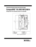
1
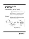
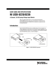
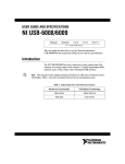
USER GUIDE AND SPECIFICATIONS NI USB-9234 4-Channel, ±5 V, 24-Bit Software-Selectable IEPE and AC/DC Analog Input Module This user guide describes how to use the National Instruments USB-9234 and includes device specifications and connector assignments. Introduction The NI USB-9234 consists of two components: an NI 9234 module and an NI USB-9162 carrier, as shown in Figure 1. NI 9234 H pe i-S N d IU U S S B e NI USB-9162 er ri -9 B 16 C 2 ar H e pe I-S N d IU U S S B er ri -9 B 16 C 2 ar NI USB-9234 Figure 1. NI USB-9234 Components Dimensions Figure 2 shows the NI USB-9234 device dimensions. Hi-Speed USB Carrier NI USB-9162 140.66 mm (5.538 in.) 120.68 mm (4.751 in.) 138.30 mm (5.445 in.) 118.26 mm (4.656 in.) 88.12 mm (3.469 in.) 25.34 mm (0.998 in.) Figure 2. NI USB-9234 Device in Millimeters (Inches) Safety Guidelines Operate the NI USB-9234 only as described in this user guide. Although the NI 9234 module may have more stringent certification standards than the NI USB-9234, when used with the NI USB-9162 carrier, the combined system may be limited. Refer to the Specifications section for more details. Note Hot Surface This icon denotes that the component may be hot. Touching this component may result in bodily injury. Do not disconnect I/O-side wires or connectors unless power has been switched off or the area is known to be nonhazardous. Caution Caution Do not the remove module unless power has been switched off or the area is known to be nonhazardous. Caution The NI USB-9234 is not certified for use in hazardous locations. NI USB-9234 User Guide and Specifications 2 ni.com Safety Guidelines for Hazardous Voltages If hazardous voltages are connected to the module, take the following precautions. A hazardous voltage is a voltage greater than 42.4 Vpk or 60 VDC to earth ground. Ensure that hazardous voltage wiring is performed only by qualified personnel adhering to local electrical standards. Caution Caution Do not mix hazardous voltage circuits and human-accessible circuits on the same module. Make sure that devices and circuits connected to the module are properly insulated from human contact. Caution Related Documentation Each application software package and driver includes information about writing applications for taking measurements and controlling measurement devices. The following references to documents assume you have NI-DAQmx 8.8 or later, and where applicable, version 7.1 or later of the NI application software. NI-DAQmx for Windows The DAQ Getting Started Guide describes how to install your NI-DAQmx for Windows software, your NI-DAQmx-supported DAQ device, and how to confirm that your device is operating properly. Select Start»All Programs»National Instruments»NI-DAQ»DAQ Getting Started Guide. The NI-DAQ Readme lists which devices are supported by this version of NI-DAQmx. Select Start»All Programs»National Instruments» NI-DAQ»NI-DAQ Readme. The NI-DAQmx Help contains general information about measurement concepts, key NI-DAQmx concepts, and common applications that are applicable to all programming environments. Select Start»All Programs»National Instruments»NI-DAQ»NI-DAQmx Help. © National Instruments Corporation 3 NI USB-9234 User Guide and Specifications LabVIEW If you are a new user, use the Getting Started with LabVIEW manual to familiarize yourself with the LabVIEW graphical programming environment and the basic LabVIEW features you use to build data acquisition and instrument control applications. Open the Getting Started with LabVIEW manual by selecting Start»All Programs»National Instruments»LabVIEW»LabVIEW Manuals or by navigating to the labview\manuals directory and opening LV_Getting_Started.pdf. Use the LabVIEW Help, available by selecting Help»Search the LabVIEW Help in LabVIEW, to access information about LabVIEW programming concepts, step-by-step instructions for using LabVIEW, and reference information about LabVIEW VIs, functions, palettes, menus, and tools. Refer to the following locations on the Contents tab of the LabVIEW Help for information about NI-DAQmx: • Getting Started»Getting Started with DAQ—Includes overview information and a tutorial to learn how to take an NI-DAQmx measurement in LabVIEW using the DAQ Assistant. • VI and Function Reference»Measurement I/O VIs and Functions—Describes the LabVIEW NI-DAQmx VIs and properties. • Taking Measurements—Contains the conceptual and how-to information you need to acquire and analyze measurement data in LabVIEW, including common measurements, measurement fundamentals, NI-DAQmx key concepts, and device considerations. LabWindows/CVI The Data Acquisition book of the LabWindows/CVI Help contains measurement concepts for NI-DAQmx. This book also contains Taking an NI-DAQmx Measurement in LabWindows/CVI, which includes step-by-step instructions about creating a measurement task using the DAQ Assistant. In LabWindows™/CVI™, select Help»Contents, then select Using LabWindows/CVI»Data Acquisition. The NI-DAQmx Library book of the LabWindows/CVI Help contains API overviews and function reference for NI-DAQmx. Select Library Reference»NI-DAQmx Library in the LabWindows/CVI Help. NI USB-9234 User Guide and Specifications 4 ni.com Measurement Studio If you program your NI-DAQmx-supported device in Measurement Studio using Visual C++, Visual C#, or Visual Basic .NET, you can interactively create channels and tasks by launching the DAQ Assistant from MAX or from within Visual Studio .NET. You can generate the configuration code based on your task or channel in Measurement Studio. Refer to the DAQ Assistant Help for additional information about generating code. You also can create channels and tasks, and write your own applications in your ADE using the NI-DAQmx API. For help with NI-DAQmx methods and properties, refer to the NI-DAQmx .NET Class Library or the NI-DAQmx Visual C++ Class Library included in the NI Measurement Studio Help. For general help with programming in Measurement Studio, refer to the NI Measurement Studio Help, which is fully integrated with the Microsoft Visual Studio .NET help. To view this help file in Visual Studio. NET, select Measurement Studio» NI Measurement Studio Help. To create an application in Visual C++, Visual C#, or Visual Basic .NET, follow these general steps: 1. In Visual Studio .NET, select File»New»Project to launch the New Project dialog box. 2. Find the Measurement Studio folder for the language you want to create a program in. 3. Choose a project type. You add DAQ tasks as a part of this step. ANSI C without NI Application Software The NI-DAQmx Help contains API overviews and general information about measurement concepts. Select Start»All Programs»National Instruments»NI-DAQ»NI-DAQmx Help. The NI-DAQmx C Reference Help describes the NI-DAQmx Library functions, which you can use with National Instruments data acquisition devices to develop instrumentation, acquisition, and control applications. Select Start»All Programs»National Instruments»NI-DAQ» NI-DAQmx C Reference Help. © National Instruments Corporation 5 NI USB-9234 User Guide and Specifications .NET Languages without NI Application Software With the Microsoft .NET Framework version 1.1 or later, you can use NI-DAQmx to create applications using Visual C# and Visual Basic .NET without Measurement Studio. You need Microsoft Visual Studio .NET 2003 or Microsoft Visual Studio 2005 for the API documentation to be installed. The installed documentation contains the NI-DAQmx API overview, measurement tasks and concepts, and function reference. This help is fully integrated into the Visual Studio .NET documentation. To view the NI-DAQmx .NET documentation, go to Start»All Programs»National Instruments»NI-DAQ»NI-DAQmx .NET Reference Help. Expand NI Measurement Studio Help»NI Measurement Studio .NET Class Library»Reference to view the function reference. Expand NI Measurement Studio Help»NI Measurement Studio .NET Class Library»Using the Measurement Studio .NET Class Libraries to view conceptual topics for using NI-DAQmx with Visual C# and Visual Basic .NET. To get to the same help topics from within Visual Studio, go to Help»Contents. Select Measurement Studio from the Filtered By drop-down list and follow the previous instructions. Device Documentation and Specifications Documentation for supported devices and accessories, including PDF and help files describing device terminals, specifications, features, and operation are on the NI-DAQmx CD that includes Device Documentation. Insert the CD, open the Device Documentation directory, and double-click the Device Documents shortcut for your language to find, view, and print device documents. Note You can also download these documents at ni.com/manuals. Training Courses If you need more help getting started developing an application with NI products, NI offers training courses. To enroll in a course or obtain a detailed course outline, refer to ni.com/training. Technical Support on the Web For additional support, refer to ni.com/support or zone.ni.com. NI USB-9234 User Guide and Specifications 6 ni.com Installing the Software Software support for the NI USB-9234 for Windows Vista/XP/2000 is provided by NI-DAQmx. The DAQ Getting Started Guide, which you can download at ni.com/manuals, offers NI-DAQmx users step-by-step instructions for installing software and hardware, configuring channels and tasks, and getting started developing an application. Installing Other Software If you are using other software, refer to the installation instructions that accompany your software. Example Programs The NI-DAQmx CD contains example programs that you can use to get started programming with the NI USB-9234. Refer to the NI-DAQmx for USB Devices Getting Started Guide that shipped with your device, which is also accessible from Start»All Programs»National Instruments» NI-DAQ for more information. Installing the NI USB-9234 Device Before installing the device, you must install the software you plan to use with the device. Refer to the Installing the Software section of this guide and the documentation included with the software for more information. Installing the NI 9234 in the NI USB-9162 Carrier The NI 9234 module and NI USB-9162 carrier are packaged separately. Refer to Figure 3, while completing the following assembly steps: 1. Make sure no signals are connected to the NI 9234 module and the USB cable is not connected to the device. 2. Remove the protective cover from the 15-pin D-SUB connector. © National Instruments Corporation 7 NI USB-9234 User Guide and Specifications Align the I/O module with the carrier, as shown in Figure 3. eed S Sp N IU Hi- 3. B BC US 2 16 -9 arr ier Figure 3. Module Installation 4. Squeeze the latches and insert the NI 9234 module into the NI USB-9162 carrier. 5. Press firmly on the connector side of the NI 9234 module until the latches lock the module into place, as shown in Figure 4. Hi- Sp N I U S B -9 16 2 eed US BC arr ier Figure 4. Locking Module into Place NI USB-9234 User Guide and Specifications 8 ni.com Mounting the NI USB-9234 Threaded inserts are located in the NI USB-9234 for mounting it to a panel. Refer to Figure 5 for the module dimensions. 85.7 mm (3.37 in.) 72.2 mm (2.84 in.) Threaded Insert M3 x 0.5 8.5 mm (0.34 in.) Max Depth 76.1 mm (3.00 in.) Figure 5. Module Dimensions Connecting the NI USB-9234 to a Computer Plug one end of the USB cable into the NI USB-9234 and the other end into an available USB port on the computer. Refer to the NI-DAQmx for USB Devices Getting Started Guide that shipped with your device, which is also accessible from Start»All Programs»National Instruments»NI-DAQ, for more information. © National Instruments Corporation 9 NI USB-9234 User Guide and Specifications LED Indicator The NI USB-9234 device has a green LED next to the USB connector. The LED indicator indicates device status, as listed in Table 1. When the device is connected to a USB port, the LED blinks steadily to indicate that the device is initialized and is receiving power from the connection. If your device is not blinking, make sure your computer has the latest version of NI-DAQmx installed on it, and that the computer is not in standby mode. Table 1. LED State/Device Status LED State Device Status Not lit Device not connected or in suspend. On, not blinking Device connected, but no module installed. Single-blink Operating normally. Double-blink Connected to USB Full-Speed port. Device performance might be affected. Refer to the Specifications section for more information. Quadruple-blink Device error. Refer to ni.com/support. NI USB-9234 User Guide and Specifications 10 ni.com Wiring the NI USB-9234 The NI USB-9234 has four BNC connectors that provide connections to four simultaneously sampled analog input channels. Each channel has a BNC connector to which you can connect a signal source. You can also enable excitation current on a per-channel basis to connect Integrated Electronic Piezoelectric (IEPE) sensors. The center pin of the connector, AI+, provides the DC signal connection. The shell of the connector, AI–, provides the excitation return path and AC signal ground reference. Refer to Figure 6 for the connector assignments for each channel. AI0+ AI0– AI1+ AI1– AI2+ AI2– AI3+ AI3– Figure 6. NI USB-9234 Connector Assignments © National Instruments Corporation 11 NI USB-9234 User Guide and Specifications Connecting Signal Sources to the NI USB-9234 You can connect ground-referenced or floating signal sensors to the NI USB-9234. To avoid picking up ground noise, use a floating connection. To further minimize ground noise, prevent the metal shells of the BNC connectors from touching each other, the modules, or the chassis. If you make a ground-referenced connection between the signal source and the NI USB-9234, make sure the voltage on the AI– shell is in the common-mode range to ensure proper operation of the NI USB-9234. The AI– shell is protected against accidental contact with overvoltages within the overvoltage protection range. Refer to the Specifications section for more information about operating voltages and overvoltage protection. Figures 7 and 8 illustrate connecting grounded and floating signal sources to the NI USB-9234. Signal Source AI+ + – NI USB-9234 Common- AI– Mode Voltage Figure 7. Connecting a Grounded IEPE Sensor to the NI USB-9234 Signal Source AI+ + – NI USB-9234 AI– Figure 8. Connecting a Floating IEPE Sensor to the NI USB-9234 The NI USB-9234 can also provide an IEPE excitation current for each channel to measure ground referenced or floating IEPE sensors. Typical IEPE sensors have a case that is electrically isolated from the IEPE electronics, so connecting the sensor to the NI USB-9234 results in a floating connection even though the case of the sensor is grounded. NI USB-9234 User Guide and Specifications 12 ni.com NI USB-9234 Circuitry The NI USB-9234 analog input channels are referenced to chassis ground through a 50 Ω resistor. To minimize ground noise, make sure that the chassis ground is connected to earth ground. Each channel is protected from overvoltages. You can configure the NI USB-9234 for AC or DC coupling for each channel. You can turn the IEPE excitation current on or off in AC-coupled mode (in software). IEPE current is not available in DC-coupled mode. The input signal on each channel is buffered, conditioned, and then sampled by a 24-bit, Delta-Sigma ADC. 2 mA IEPE On/Off AC/DC Coupling AI+ + ADC AI– CurrentLimiting Diodes 50 Ω – CommonAmplifier Mode and Bias Prefilter Current NI USB-9234 Figure 9. Input Circuitry for One Channel The NI USB-9234 uses common-mode bias current to bias the current-limiting diodes when IEPE current is turned off. When using grounded signal sources, this current causes an error that is dependent on the AI– lead impedance. This error is approximately 50 ppm of range and 15 ppm of reading per Ω of AI– impedance. The common-mode bias current causes an error only with grounded sources and is not an issue with floating signal sources. For best accuracy, use a floating connection or use low-impedance leads when connecting grounded signal sources. Signal Source AI+ NI USB-9234 + – AI– Lead Impedance AI– CommonMode Bias Current Figure 10. Measurement Error Introduced by Common-Mode Bias Current © National Instruments Corporation 13 NI USB-9234 User Guide and Specifications The NI USB-9234 also has TEDS circuitry. For more information about TEDS, go to ni.com/info and enter rdteds. Understanding NI USB-9234 Filtering The NI USB-9234 uses a combination of analog and digital filtering to provide an accurate representation of in-band signals while rejecting out-of-band signals. The filters discriminate between signals based on the frequency range, or bandwidth, of the signal. The three important bandwidths to consider are the passband, the stopband, and the alias-free bandwidth. The NI USB-9234 represents signals within the passband as quantified primarily by passband flatness and phase nonlinearity. The filters reject frequencies within the stopband as much as possible, as quantified by stopband rejection. All signals that appear in the alias-free bandwidth are either unaliased signals or signals that have been filtered by at least the amount of the stopband rejection. Passband The signals within the passband have frequency-dependent gain or attenuation. The small amount of variation in gain with frequency is called the passband flatness. The digital filters of the NI USB-9234 adjust the frequency range of the passband to match the data rate. Therefore, the amount of gain or attenuation at a given frequency depends on the data rate. Figure 11 shows typical passband flatness for 51.2 kS/s data rate. Gain (dB) 0.025 0.000 –0.025 –0.050 0 5 10 15 20 Frequency (kHz) 25 30 Figure 11. NI USB-9234 Typical Passband Response NI USB-9234 User Guide and Specifications 14 ni.com Stopband The filter significantly attenuates all signals above the stopband frequency. The primary goal of the filter is to prevent aliasing. Therefore, the stopband frequency scales precisely with the data rate. The stopband rejection is the minimum amount of attenuation applied by the filter to all signals with frequencies within the stopband. Alias-Free Bandwidth Any signal that appears in the alias-free bandwidth of the NI USB-9234 is not an aliased artifact of signals at a higher frequency. The alias-free bandwidth is defined by the ability of the filter to reject frequencies above the stopband frequency, and it is equal to the data rate minus the stopband frequency. Understanding NI USB-9234 Data Rates The frequency of a master timebase (fM) controls the data rate (fs) of the NI USB-9234. The NI USB-9234 includes an internal master timebase with a frequency of 13.1072 MHz, but the module also can accept an external master timebase or export its own master timebase. Refer to the software help for information about configuring the master timebase source for the NI USB-9234. The following equation provides the available data rates of the NI USB-9234: ( f M ) ÷ 256 fs = -----------------------n where n is any integer from 1 to 31. The data rate must remain within the data range. Refer to the Specifications section for more information about the data rate range. When using the internal master timebase of 13.1072 MHz, the result is data rates of 51.2 kS/s, 25.6 kS/s, 17.067 kS/s, and so on down to 1.652 kS/s, depending on the value of n. When using an external timebase with a frequency other than 13.1072 MHz, the NI USB-9234 has a different set of data rates. © National Instruments Corporation 15 NI USB-9234 User Guide and Specifications Specifications The following specifications are typical for the range 0 to 60 °C unless otherwise noted. Input Characteristics Number of channels................................4 analog input channels ADC resolution.......................................24 bits Type of ADC ..........................................Delta-Sigma (with analog prefiltering) Sampling mode .......................................Simultaneous Type of TEDS supported ........................IEEE.1451.4 TEDS Class I (interface) Internal master timebase (fM) Frequency ........................................13.1072 MHz Accuracy..........................................±50 ppm max Data rate range (fs) using internal master timebase Minimum .........................................1.652 kS/s Maximum ........................................51.2 kS/s Data rate range (fs) using external master timebase Minimum .........................................0.391 kS/s Maximum ........................................52.734 kS/s f M ÷ 256 - , n = 1, 2, …, 31 Data rates (fs) ..........................................------------------n Input coupling.........................................AC/DC (software-selectable) AC cutoff frequency –3 dB ...............................................0.5 Hz typ –0.1 dB ............................................4.6 Hz max NI USB-9234 User Guide and Specifications 16 ni.com AC cutoff frequency response Gain (dB) 0.5 0.0 –0.5 –1.0 0 1 2 3 5 6 7 4 Frequency (Hz) 8 9 10 Input range ............................................. ±5 V AC voltage full-scale range Minimum ........................................ ±5 Vpk Typical ............................................ ±5.1 Vpk Maximum........................................ ±5.2 Vpk Common-mode voltage (AI– to earth ground) ............................. ±2 V max IEPE excitation current (software-selectable on/off) Minimum ........................................ 2.0 mA Typical ............................................ 2.1 mA Power-on glitch ...................................... 90 mA for 10 ms IEPE compliance voltage ....................... 19 V max If you are using an IEPE sensor, use the following equation to make sure that your configuration meets the IEPE compliance voltage range. V common – mode + V bias + V full – scale must be 0 to 19 where Vcommon-mode is the common-mode voltage of the NI USB-9234, Vbias is the bias voltage of the IEPE sensor, Vfull-scale is the full-scale voltage of IEPE sensor © National Instruments Corporation 17 NI USB-9234 User Guide and Specifications Overvoltage protection (with respect to chassis ground) For a signal source connected to AI+ and AI– ................................±30 V For a low-impedance source connected to AI+ and AI– ...............–6 to 30 V Input delay ..............................................3.2 ms + 38.4 fs Accuracy1 Percent of Reading (Gain Error) Percent of Range* (Offset Error) Calibrated max (–40 to 70 °C) 0.34%, ±0.03 dB ±0.14%, 7.1 mV Calibrated typ (25 °C ±5 °C) 0.05%, ±0.005 dB ±0.006%, 0.3 mV Uncalibrated max (–40 to 70 °C) 1.9%, ±0.16 dB ±0.27%, 13.9 mV Uncalibrated typ (25 °C ±5 °C) 0.48%, ±0.04 dB ±0.04%, 2.3 mV Measurement Conditions * Range = 5.1 Vpk Gain drift Typical.............................................0.14 mdB/°C (16 ppm/°C) Maximum ........................................0.45 mdB/°C (52 ppm/°C) Offset drift Typical.............................................19.2 mV/°C Maximum ........................................118 mV/°C Channel-to-channel matching Gain Typical......................................0.01 dB Maximum .................................0.04 dB Phase ( fin in kHz) ............................fin · 0.045° + 0.04 max Passband Frequency ........................................0.45 · fs Flatness (fs = 51.2 kS/s) ...................±40 mdB (pk-to-pk max) 1 Refer to the NI USB-9234 Circuitry section for information regarding grounded signal sources and measurement accuracy. NI USB-9234 User Guide and Specifications 18 ni.com Phase nonlinearity (fs = 51.2 kS/s) ................................ ±0.45° max Stopband Frequency........................................ 0.55 · fs Rejection ......................................... 100 dB Alias-free bandwidth.............................. 0.45 · fs Oversample rate ..................................... 64 · fs Crosstalk (1 kHz) ................................... –110 dB CMRR (fin ≤ 1 kHz) Minimum ........................................ 40 dB Typical ............................................ 47 dB SFDR (fin = 1 kHz, –60 dBFS) .............. 120 dB Idle channel noise and noise density Idle Channel 51.2 kS/s 25.6 kS/s 2.048 kS/s Noise 97 dBFS 99 dBFS 103 dBFS 50 μVrms 40 μVrms 25 μVrms 310 nV/√Hz 350 nV/√Hz 780 nV/√Hz Noise density Input impedance Differential...................................... 305 kΩ AI– (shield) to chassis ground ........ 50 Ω Total harmonic distortion (THD) Input Amplitude 1 kHz, –40 to 70 °C 8 kHz, –40 to 70 °C –1 dBFS –95 dB –87 dB –20 dBFS –95 dB –80 dB Intermodulation distortion (–1 dBFS) DIN 250 Hz/8 kHz 4:1 amplitude ratio .......................... –80 dB CCIF 11 kHz/12 kHz 1:1 amplitude ratio .......................... –93 dB © National Instruments Corporation 19 NI USB-9234 User Guide and Specifications Power Requirements Current consumption from USB.............500 mA, max Suspend mode..................................2.5 mA, max Bus Interface USB specification ...................................USB 2.0 Hi-Speed Physical Characteristics Dimensions .............................................12.1 cm × 8.6 cm × 2.5 cm (4.75 in. × 3.37 in. × 0.99 in.) Weight ....................................................Approx. 250 g (8.8 oz) Safety If you need to clean the module, wipe it with a dry towel. Safety Voltages Connect only voltages that are within the following limits. Channel-to-earth ground.........................±30 V max, Measurement Category I Isolation Channel-to-channel..........................No isolation between channels Channel-to-earth ground..................No isolation between channels and earth ground Measurement Category I is for measurements performed on circuits not directly connected to the electrical distribution system referred to as MAINS voltage. MAINS is a hazardous live electrical supply system that powers equipment. This category is for measurements of voltages from specially protected secondary circuits. Such voltage measurements include signal levels, special equipment, limited-energy parts of equipment, circuits powered by regulated low-voltage sources, and electronics. Caution Do not connect the NI USB-9234 to signals or use for measurements within Measurement Categories II, III, or IV. NI USB-9234 User Guide and Specifications 20 ni.com Safety Standards This product is designed to meet the requirements of the following standards of safety for electrical equipment for measurement, control, and laboratory use: • IEC 61010-1, EN-61010-1 • UL 61010-1, CSA 61010-1 Note For UL and other safety certifications, refer to the product label or visit ni.com/ certification, search by model number or product line, and click the appropriate link in the Certification column. Hazardous Locations The NI USB-9234 is not certified for use in hazardous locations. Environmental The NI USB-9234 device is intended for indoor use only. Operating temperature............................ 0 to 60 °C Storage temperature ............................... –40 to 85 °C Ingress protection ................................... IP 40 Operating humidity (IEC 60068-2-56) ................................... 10 to 90% RH, noncondensing Storage humidity (IEC 6008-2-56) ..................................... 5 to 95% RH, noncondensing Maximum altitude .................................. 2,000 m Pollution Degree (IEC 60664) ............... 2 Electromagnetic Compatibility This product is designed to meet the requirements of the following standards of EMC for electrical equipment for measurement, control, and laboratory use: Note • EN 61326 EMC requirements; Minimum Immunity • EN 55011 Emissions; Group 1, Class A • CE, C-Tick, ICES, and FCC Part 15 Emissions; Class A For EMC compliance, operate this device with shielded cabling. © National Instruments Corporation 21 NI USB-9234 User Guide and Specifications CE Compliance This product meets the essential requirements of applicable European Directives, as amended for CE marking, as follows: • 2006/95/EC; Low-Voltage Directive (safety) • 2004/108/EC; Electromagnetic Compatibility Directive (EMC) Refer to the Declaration of Conformity (DoC) for this product for any additional regulatory compliance information. To obtain the DoC for this product, visit ni.com/ certification, search by model number or product line, and click the appropriate link in the Certification column. Note Environmental Management National Instruments is committed to designing and manufacturing products in an environmentally responsible manner. NI recognizes that eliminating certain hazardous substances from our products is beneficial not only to the environment but also to NI customers. For additional environmental information, refer to the NI and the Environment Web page at ni.com/environment. This page contains the environmental regulations and directives with which NI complies, as well as other environmental information not included in this document. Waste Electrical and Electronic Equipment (WEEE) At the end of their life cycle, all products must be sent to a WEEE recycling center. For more information about WEEE recycling centers and National Instruments WEEE initiatives, visit ni.com/environment/weee.htm. EU Customers ⬉ᄤֵᙃѻક∵ᶧࠊㅵ⧚ࡲ⊩ ˄Ё RoHS˅ Ёᅶ᠋ National Instruments ヺড়Ё⬉ᄤֵᙃѻકЁ䰤ࠊՓ⫼ᶤѯ᳝ᆇ⠽䋼ᣛҸ (RoHS)DŽ ݇Ѣ National Instruments Ё RoHS ড়㾘ᗻֵᙃˈ䇋ⱏᔩ ni.com/environment/rohs_chinaDŽ (For information about China RoHS compliance, go to ni.com/environment/rohs_china.) Calibration You can obtain the calibration certificate and information about calibration services for the NI USB-9234 at ni.com/calibration. Calibration interval .................................1 year NI USB-9234 User Guide and Specifications 22 ni.com Where to Go for Support The National Instruments Web site is your complete resource for technical support. At ni.com/support you have access to everything from troubleshooting and application development self-help resources to email and phone assistance from NI Application Engineers. National Instruments corporate headquarters is located at 11500 North Mopac Expressway, Austin, Texas, 78759-3504. National Instruments also has offices located around the world to help address your support needs. For telephone support in the United States, create your service request at ni.com/support and follow the calling instructions or dial 512 795 8248. For telephone support outside the United States, contact your local branch office: Australia 1800 300 800, Austria 43 662 457990-0, Belgium 32 (0) 2 757 0020, Brazil 55 11 3262 3599, Canada 800 433 3488, China 86 21 5050 9800, Czech Republic 420 224 235 774, Denmark 45 45 76 26 00, Finland 358 (0) 9 725 72511, France 01 57 66 24 24, Germany 49 89 7413130, India 91 80 41190000, Israel 972 3 6393737, Italy 39 02 41309277, Japan 0120-527196, Korea 82 02 3451 3400, Lebanon 961 (0) 1 33 28 28, Malaysia 1800 887710, Mexico 01 800 010 0793, Netherlands 31 (0) 348 433 466, New Zealand 0800 553 322, Norway 47 (0) 66 90 76 60, Poland 48 22 3390150, Portugal 351 210 311 210, Russia 7 495 783 6851, Singapore 1800 226 5886, Slovenia 386 3 425 42 00, South Africa 27 0 11 805 8197, Spain 34 91 640 0085, Sweden 46 (0) 8 587 895 00, Switzerland 41 56 2005151, Taiwan 886 02 2377 2222, Thailand 662 278 6777, Turkey 90 212 279 3031, United Kingdom 44 (0) 1635 523545 National Instruments, NI, ni.com, and LabVIEW are trademarks of National Instruments Corporation. Refer to the Terms of Use section on ni.com/legal for more information about National Instruments trademarks. Other product and company names mentioned herein are trademarks or trade names of their respective companies. For patents covering National Instruments products, refer to the appropriate location: Help»Patents in your software, the patents.txt file on your CD, or ni.com/patents. © 2008 National Instruments Corporation. All rights reserved. 372307A-01 May08