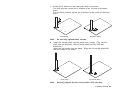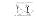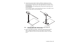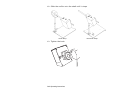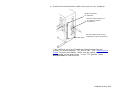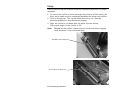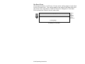
1
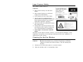
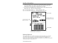
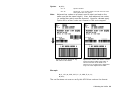
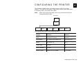
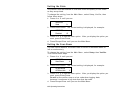
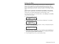
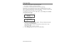
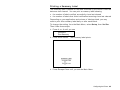
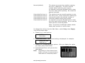
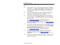
Operating Instructions Monarch® 938™ Verifier 0 28028 TC0938OI Rev. AH 5/10 ©2007 Avery Dennison Corp. All rights reserved. Each product and program carries a respective written warranty, the only warranty on which the customer can rely. Avery Dennison Corp. reserves the right to make changes in the product, the programs, and their availability at any time and without notice. Although Avery Dennison Corp. has made every effort to provide complete and accurate information in this manual, Avery Dennison Corp. shall not be liable for any omissions or inaccuracies. Any update will be incorporated in a later edition of this manual. 2003 Avery Dennison Corp. All rights reserved. No part of this publication may be reproduced, transmitted, stored in a retrieval system, or translated into any language in any form by any means, without the prior written permission of Avery Dennison Corp. Trademarks Monarch, 938, 9855®, and 9860 are trademarks of Avery Dennison Retail Information Services LLC. Avery Dennison is a trademark of Avery Dennison Corporation. Microsoft and Windows are trademarks of Microsoft Corporation in the United States and/or other countries. Excerpts reprinted from the SV Series Operator’s Guide with permission from RJS. Avery Dennison Printer Systems Division 170 Monarch Lane Miamisburg, OH 45342 FCC Notice This device has been tested and found to comply with the limits for a Class B digital device, pursuant to Part 15 of the FCC Rules. These limits are designed to provide reasonable protection against harmful interference in a residential installation. This device generates, uses, and can radiate radio frequency energy and, if installed and used in accordance with the instruction, may cause harmful interference to radio communications. However, there is no guarantee that interference will not occur in a particular installation. If this device does cause harmful interference to radio or television reception, the user is encouraged to try to correct the interference by one or more of the following measures: Reorient or relocate the receiving antenna. Increase the separation between the computer and receiver. Connect the computer into an outlet on a circuit different from that to which the receiver is connected. Consult the dealer or an experienced radio/TV technician for help. Caution: Any changes or modifications not expressly approved by the grantee of this device could void the user’s authority to operate the equipment. Statement of FCC Compliance: Canada This Class B digital apparatus meets all requirements of the Canadian interference-Causing Equipment Regulations. Cet appareil numénque de la classe B respecte toutes les exigences du Règlement sur le maténel brouilleur du Canada. CE: The unit will contain NRTL and/or CE quality assurance labels. This equipment generates, uses, and can radiate radio frequency energy and, if not installed and used in accordance with this operator’s manual, may cause harmful interference to radio communications. Operating this equipment in a residential area is likely to cause harmful interference in which case the user is responsible for correction. Use with NRTL-Listed Equipment The verifier should be used only with printers that are NRTL listed. The verifier is intended to be supplied by a NRTL Listed power supply (QQGQ) or (EPBU) or receives power from the host unit (NRTL Listed Printer), output rated 5Vdc, minimum 300mA maximum 1A. Laser Scanner Safety IEC Class3; CDRH Class III. Cautions: Never stare directly into the laser beam. Never stare directly at a reflected image of the laser beam. Avoid exposure to the laser beam. Use of controls or adjustments or performance of procedures other than those specified herein may result in hazardous radiation exposure. Use the verifier only with NRTL listed bar code printers. These laser light caution labels must be affixed to your verifier: If they are not, contact Monarch immediately.] Laser light - Do not stare into the beam. We shall not be liable for direct, indirect, or consequential damages, costs, expenses, lost profits, or lost savings resulting from the use, operation, or malfunction of the verifier. Cleaning the Verifier Window Clean the verifier window whenever the window appears to be dirty or smeared. Caution: Do not use solvents (e.g., alcohol or acetone) or abrasive cleaners to clean the verifier window. This will damage the window. 1. Moisten a soft cloth with water or a screen cleaner. 2. Wipe the window until it is completely clean. TA B L E O F C O N T E N T S Getting Started ............................................................................................1-1 Using this Manual ........................................................ 1-1 Unpacking the Verifier.................................................. 1-2 Overview .................................................................... 1-2 Installation & Setup .....................................................................................2-1 Installing the Verifier ................................................... 2-1 Connecting the Cables .............................................. 2-6 Connecting the Cables .............................................. 2-7 Installing the Printer ................................................. 2-8 Setup ....................................................................... 2-12 Bar Code Travel Speed Considerations ........................ 2-13 Parallel Bar Code Direction ..................................... 2-13 Parallel Bar Code Positioning Specifications ............. 2-13 No-Scan Zone ........................................................ 2-14 Calibrating the Verifier ................................................................................3-1 Calibrating the Verifier ................................................. 3-1 Verifier Information ...................................................... 3-2 Defining Option 62 ................................................... 3-2 Configuring the Printer ................................................................................4-1 Setting the State ......................................................... 4-2 Setting the Scan Beam ................................................. 4-2 Setting the Mode ......................................................... 4-3 Clearing Data .............................................................. 4-4 Printing a Summary Label............................................. 4-5 Detecting the Cable ..................................................... 4-6 Setting the Error Action ................................................ 4-6 Troubleshooting ..........................................................................................5-1 Verifier Errors ............................................................. 5-2 Verifier LED Indicators ................................................. 5-3 Specifications ............................................................................................. A-1 Laser Scanner ..............................................................A- 2 i ii G E T T I N G S TA R T E D 1 Use these Operating Instructions to set up, use, and configure the Monarch 938 verifier. The verifier works with the Monarch 9855 printer and 9860 printer with knife. The verifier can scan a wide variety of one-dimensional parallel bar codes. However, it cannot scan MSI bar codes or two-dimensional bar codes. Information in this document supercedes information in previous versions. Check our Web site for the latest documentation and release information. The verifier saves data from each bar code it scans. You can use immediate commands to upload scan grade data and bar code data from the verifier. Refer to the Packet Reference Manual available on our Web site for more information. Using this Manual Manual content summary: Chapter Contents 1 Getting Started Information you should know before using the verifier. 2 Installation & Setup Installing and positioning the verifier. 3 Calibrating the Verifier Calibrating the verifer. 4 Configuring the Printer Setting the printer to work with your verifier. 5 Troubleshooting Common problems and their solutions. A Specifications Verifier and laser scanner specifications. Getting Started 1-1 Unpacking the Verifier After you unpack the verifier, you should have the following: 938 verifier I/O cable 9-pin communications cable base plate (with two shafts, stand, mounting block, L-bracket, and attaching parts) calibration label SV Series Operator’s Guide (You will need to refer to this manual). Note: Do not lose the calibration label! You need it to configure the verifier. Keep the box and packaging material in case the verifier ever needs repair. Overview Have your System Administrator follow these steps before you use the verifier: 1. Install and set up the verifier. See Chapter 2, “Installation & Setup,” for more information. 2. Calibrate the verifier. See Chapter 3, “Calibrating the Verifier,” for more information. 3. Configure the printer to enable the verifier. See Chapter 4, “Configuring the Printer,” for more information. 1-2 Operating Instructions I N S TA L L AT I O N & S E T U P 2 This chapter explains how to install the verifier and connect all the cables. You need a Phillips screwdriver and a 3/32 Hex key (wrench). Throughout this chapter, the reference to “knife setup” is for the 9860 printer; the reference to “non-knife setup” is for the 9855 printer. The verifier does not work with a 9855 printer using the Monarch 926 knife. Installing the Verifier 1. Turn off the printer. 2. Place the printer on a firm work surface. 3. Remove the following items from their packaging: (1) (1) (4) (1) (5) (6) 4. base plate (2) shafts stand (1) mounting block feet (1) L-bracket ¼” plain cork washer (1) ¼”-20x1¼” screw M4x12 screws with attached lock washers #10-32x1/4” set screws Turn the base plate upside down and attach the adhesive feet in each corner. Make sure the base plate looks like the one pictured before you attach the feet. Pay attention to the pattern of the mounting holes. Installation & Setup 2-1 5. Turn the base plate right side up. 6. Using three screws with attached lock washers, attach the stand to the base plate: For knife printers, use the three holes that are on the left side of the base plate. For non-knife printers, use the three holes in the center of the base plate. Knife Setup Note: Non-Knife Setup Do not fully tighten these screws. It is easier to attach the shafts, bracket, and verifier before attaching the printer to the base plate. 2-2 Operating Instructions 7. Attach the L-bracket to the base plate with two screws: For knife printers, attach the L-bracket to the left side of the base plate. For non-knife printers, attach the L-bracket to the center of the base plate. Knife Setup Note: 8. Non-Knife Setup Do not fully tighten these screws. Insert the vertical shaft into the stand until it stops. (The vertical shaft has one diameter; the horizontal shaft has two different diameters.) Insert the set screws into the stand. Align the flat on the shaft with the set screws in the stand. Knife Setup Note: Non-Knife Setup Securely tighten the set screws with a 3/32 Hex key. Installation & Setup 2-3 9. Slide the mounting block onto the shaft as far as it will go. Insert the set screws into the mounting block. Align the flat on the shaft with the set screws in the mounting block. Tighten these set screw s Knife Setup Note: Non-Knife Setup Securely tighten the set screws with a 3/32 Hex key. 2-4 Operating Instructions 10. Insert the horizontal shaft (with two different diameters) into the mounting block as shown. Insert the set screws into the top of the mounting block. Align the flat on the shaft with the set screws in the mounting block. For knife printers, the shaft should be flush with the left edge of the mounting block. For non-knife printers, insert the shaft so the step in the shaft is flush with the right edge of the mounting block. Knife Setup Note: Non-Knife Setup Securely tighten ALL the set screws in the shaft and mounting block with a 3/32 Hex key. 11. Look at the stand from above. Adjust the stand so the horizontal shaft is parallel (aligned) with the front edge of the base plate. Securely tighten the three screws attaching the stand to the base plate. Installation & Setup 2-5 12. Slide the verifier onto the shaft until it stops. Knife Setup 13. Tighten the knob. 2-6 Operating Instructions Non-Knife Setup Connecting the Cables 1. Turn off the printer. 2. Connect the I/O cable to the verifier. 3. Connect the communication cable from the verifier to the printer primarily to update the verifier for each bar code on the label. Communication Cable I/O Cable Knife Setup Non-Knife Setup 4. Lay the cables on top of the base plate (the printer sits on top of them). Installation & Setup 2-7 Installing the Printer 1. For knife printers, remove the bottom screw from the right-hand corner of the printer’s cover. Keep the screw, because you need to re-use it. For non-knife printers, use a Phillips screwdriver to remove the base cover. Keep the screw, because you need to re-use it. However, you can throw away the base cover. Remo ve this screw Knife Setup Base cover Non-Knife Setup 2. Align the hole in the printer over the hole in the base plate. Make sure the cables underneath the printer are flat and not in the way. 2-8 Operating Instructions 3. Attach the printer using the shoulder screw provided without the cork washer. Tighten securely. If the printer is not held down securely, then add the cork washer provided with the printer. Use your finger to tighten this screw. Ma y or ma y not need this cork w asher. 4. Attach the L-bracket to the printer using the screw you removed. For knife printers, attach the L-bracket to the side of the printer. For non-knife printers, attach the L-bracket to the front of the printer where the printer’s base cover was attached. Knife Setup Non-Knife Setup 5. Align the printer if necessary and tighten the screws in the L-bracket. 6. Align the verifier so the verifier’s beam is centered in the feed path. See “Setup” for beam positioning. Securely tighten ALL the set screws. Installation & Setup 2-9 7. A cable tube is provided with each verifier to hide the cables from view. Slightly open the cable tube and slide the cables through it. Hold the cable tube against the vertical stand’s shaft and secure the cable tube to the shaft with the cable ties. Secure cable ties here 8. Connect the other end of the I/O cable (with the 8-pin mini-din connector) to the back of the printer. 2-10 Operating Instructions 9. Connect the communication cable to the port on your computer. Verifier Connector for I/O Cable Use this 9-pin verifier port for verifier to printer connections Use this 25-pin serial port for computer to printer connections If the verifier’s serial or I/O cable are disconnected from the printer, the printer displays “773 Verifier Fail.” See “Detecting the Cable” for more information. Make sure the cables are connected between the verifier and printer. If error 773 appears, press Escape/Clear to clear the error. Installation & Setup 2-11 Setup Verifier positioning and system setup are extremely important for proper operation. 1. To control the verifier’s beam (through the printer’s offline menu), the 9-pin serial cable must be connected between the printer and verifier. 2. Turn on the printer. The verifier beam also turns on. See the following graphics to align the beam properly. 3. Align the verifier’s red beam with the white lines as shown. The proper angle for the verifier is 22. Note: Do not let the verifier’s beam stop on a bar code when logging data, because it logs unwanted data. Ai m beam onto w hite line Knife Setup Ai m beam onto w hite line Non-Knife Setup 2-12 Operating Instructions Bar Code Travel Speed Considerations A bar code should be present in the beam for at least five scans for most reliable operation. The verifier performs a minimum of 100 scans/analyses per second. At that rate, each analysis is accomplished in 10 milliseconds max. Therefore, a bar code must be in the beam for at least 50 milliseconds to be reliably analyzed. Parallel Bar Code Direction In parallel bar code (picket fence) travel direction, a bar code is in the laser beam throughout the height of the shortest bar in the code. An easy way to estimate the fastest speed the code can travel through the beam is to divide the height of the shortest bar in the code by the maximum time required for the verifier to take five scans of the code. Example: Calculate the maximum travel speed where the shortest bar height in a code is .5 inches and the verifier being used performs a minimum of 100 scans/analyses per second. Five scans requires 50 milliseconds (.05 seconds) to gather, so .5 inches (bar code height) divided by .05 seconds (time needed to gather 5 scans) = 10 inches/second. Therefore, the maximum speed the code can travel through the beam is 10 inches per second. Vertical distance between bar codes is also a speed consideration in parallel bar code direction. The verifier must have five continuous scans where no bar code is detected to reliably exit a bar code when operating in the standard operation mode. Assuming 100 scans per second minimum, this means the vertical distance between the codes must take at least 50 milliseconds to pass through the laser beam. Calculate the maximum speed by measuring the shortest vertical space between bar codes on a label (or between labels.) Divide this distance by .050 (seconds). The result is the fastest speed the codes can move through the beam. For more detailed information about the vertical distance between bars, refer to the SV Series Operator’s Guide. The slower of the two print speeds calculated above for bar height and gap height is the maximum recommended speed for parallel bar code travel direction. Parallel Bar Code Positioning Specifications Four codes across maximum Horizontal gap between codes: 0.5 inch (13 mm) minimum Maximum number of codes per label: 10 Installation & Setup 2-13 No-Scan Zone Allow approximately a 0.50-inch (13 mm) at the trailing edge of each label for the no-scan zone. The trailing edge is the edge of the label that exits the printer last; regardless of how the format is designed on the label. Do not place bar codes in the no-scan zone. Trailing Edge Leading Edge 4” w ide b y 1.2” tall label 2-14 Operating Instructions Shaded area (trailing edge) is the noscan zone. C A L I B R AT I N G T H E V E R I F I E R 3 This chapter explains how to calibrate and configure the verifier. Calibrating the Verifier At initial setup, calibrate the verifier to ensure the scanning distance and orientation is within device limits. A calibration label is included in the verifier’s box. Store the calibration label in a clean location. 1. Remove all bar codes from the laser beam path. 2. Place the supplied calibration label in the laser beam in the same position (distance and angle) as the labels to be verified will be scanned. 3. Press and hold the RESET button on the verifier until the calibration LED begins to flash. 4. Release the RESET button immediately after the calibration LED begins flashing. 5. If calibration is successful, the laser beam turns off and the calibration LED turns off. Remove the calibration label from the beam path. Press and release the RESET button (the beam turns on). The verifier is ready to operate. 6. If calibration is unsuccessful, the calibration LED is either on steadily or flashing. In this case, repeat the calibration procedure. Once calibration is successful, re-calibration is not required unless the verifier unit has been moved – either on its mounting stand or to a new location. Keep the laser beam exit window clean. Dirt, dust, fingerprints, etc. on the exit window can affect calibration. See the cleaning procedures at the beginning of this manual keep the scanning window clean. Calibrating the Verifier 3-1 Verifier Information There is a 0.50-inch no scan zone on the trailing edge of each label. The trailing edge is the edge of the label that exits the printer last; regardless of how the format is designed on the label. You cannot verify adjacent bar codes that do not start and end on the same print row. See the following graphic. B,3,13,V,310,28,8,4,50,8,L,0¦ Postal Code bar code B,4,13,V,355,200,8,4,50,8,L,0¦ Tracking Number bar code Trailing Edge “Tracking Number” bar code begins at row 355. “ P ostal Code” bar code begins at row 310. Leading Edge The verifier cannot verif y the “ postal code” and “ tracking number” bar codes, because the y do not start and end on the same row . Defining Option 62 This option allows the verifier to bypass (skip) bar code(s) on a format. The verifier does not scan any bar code with option 62 applied to it. Refer to the Packet Reference Manual available on our Web site for more information about using Option 62. 3-2 Operating Instructions Syntax R,62¦ R1. R R2. 62 Note: Option Header. Option 62. The verifier does not scan the bar code associated with this option. Adjacent bar codes on a format need to start and end on the same row (be the same height). Also, both adjacent bar codes (or neither bar code) must be scanned. However, do not apply Option 62 to all bar codes on a format or 764 errors appear. Option 62 can be applied to an y bar code on this format. Option 62 must be applied to BOTH adjacent bar codes. The verifier’s beam scans the entire w idth of the label; it cannot scan half of the w idth. The verifier errors if Option 62 is applied to onl y one of the adjacent bar codes. Example B,1,12,F,110,115,1,2,120,5,L,0¦ R,62¦ The verifier does not scan or verify this UPCA bar code on the format. Calibrating the Verifier 3-3 3-4 Operating Instructions CONFIGURING THE PRINTER 4 This chapter explains how to configure the printer to use the verifier. You can set the state, scan beam, mode, clear data, print a summary label, and detect the cable. Note: Make sure the printer and verifier are connected with the communications cable. MAIN MENU S e tup Verifier State Scan Beam Mode Clear D a ta Prin t S um ma ry C ab le Detect The options are listed in the following table. Option Choices Default State Enabled/Disabled Disabled Scan Beam Off When Idle/Always On Off When Idle Mode Def 2/Def 19 Def 2 Clear Data Yes/No No Print Summary Yes/No No Cable Detect None/I-O/I-O & Data I-O & Data Configuring the Printer 4-1 Setting the State The verifier must be enabled to scan and check the quality of bar codes as they are printed. To change the setting, from the Main Menu, select Setup, Verifier, then follow these steps. 1. Press or until you see VERIFIER State 2. Press Enter/Pause. The current setting is displayed, for example: VERIFIER Disabled 3. Press or to see the other option. After you display the option you want, press Enter/Pause. 4. Press Escape/Clear until you see the Main Menu. Setting the Scan Beam You can control whether the scan beam is turned off between labels or left on continuously. To change the setting, from the Main Menu, select Setup, then Verifier. Then follow these steps. 1. Press or until you see VERIFIER Scan Beam 2. Press Enter/Pause. The current setting is displayed, for example: SCAN BEAM Off When Idle 3. Press or to see the other option. After you display the option you want, press Enter/Pause. Do not let the verifier stop on a bar code when logging data, because it continues to log data from that bar code. 4. Press Escape/Clear until you see the Main Menu. 4-2 Operating Instructions Setting the Mode You must select the verifier mode for the verifier to operate correctly. Mode 2 (Def 2) specifies nine different parameters to verify: ANSI defects, decodability, and grade; quiet zones; partial decodes, decode errors, passing percent decode; minimum number of I2of5 digits; and no read. Mode 19 (Def 19) specifies all parameters from Mode 2, plus contrast grade, wide to narrow ratio, and minimum and maximum X-dimensions. Check with your System Administrator on which mode to use. To change the setting, from the Main Menu, select Setup, then Verifier. Then follow these steps. 1. Press or until you see VERIFIER Mode 2. Press Enter/Pause. The current setting is displayed, for example: Select Config Def 2 3. Press or to see the other options. After you display the option you want, press Enter/Pause. Are you sure? No 4. Select Yes or No. If you select “Yes,” the file is sent immediately to the verifier. This configuration is active for all formats until another verifier configuration packet is specified. 5. Press Escape/Clear until you see the Main Menu. Configuring the Printer 4-3 Clearing Data The verifier keeps track of the following items: the number of labels verified sucessfully the number of labels that failed verification/scanning Depending on your application and volume of labels printed, you may want to clear this data daily or after each batch. This data is stored and only cleared when you select “Yes” to clear data. To change the setting, from the Main Menu, select Setup, then Verifier. Then follow these steps. 1. Press or until you see 2. VERIFIER Clear Data Press Enter/Pause. Are You Sure? No 3. Press or to see the other option. After you display the option you want, press Enter/Pause. If you select “Yes,” all data collected since the last time it was cleared is erased. If you select “No,” no data is erased. 4. Press Escape/Clear until you see the Main Menu. 4-4 Operating Instructions Printing a Summary Label The summary label is based on the data collected by the verifier since the data was last cleared. You can print a summary label showing the number of labels verified sucessfully since last cleared the number of labels that failed verification/scanning since last cleared Depending on your application and volume of labels printed, you may want to print this summary label daily or after each batch. To change the setting, from the Main Menu, select Setup, then Verifier. Then follow these steps. 1. Press or until you see VERIFIER Print Summary 2. Press Enter/Pause. The summary label prints. 3. Press Escape/Clear until you see the Main Menu. Configuring the Printer 4-5 Detecting the Cable You can configure the printer to detect when the serial and/or the I/O (input/output) cable is disconnected from the verifier. To change the setting, from the Main Menu, select Setup, then Verifier. Then follow these steps. 1. Press or until you see VERIFIER Cable Detect 2. Press Enter/Pause. The current setting is displayed, for example: VERIFIER None 3. Press or to see the other options. After you display the option you want, press Enter/Pause. If you select “None,” the verifier does not detect when a cable is disconnected. To be notified when any cable (serial or I/O) is disconnected, select the I/O & Data option. If a cable is disconnected, error 773 appears. Check the connections between the verifier, printer, and host. 4. Press Escape/Clear until you see the Main Menu. Setting the Error Action The recovery action from an error condition is in the Setup, Supply menu. You can change how the printer responds to a bad scan. The choices include normal and overstrike/continue one to five consecutive bad scans. The overstrike pattern is created to prevent someone from using a bad label. Selecting overstrike and continue 1x-5x sets the number of times the printer prints an overstrike pattern on consecutively bad labels before generating an error. The user must clear the error before operation can continue. 4-6 Operating Instructions Do not use the overstrike action with Peel mode Linerless supplies String tag supplies For more information about the error actions, see the following table: Error Action Standard Peel Verifier with Peel RFID with Peel Overstrike/Continue 1-5 No No No Normal (no overstrike) Yes Yes Yes Consider this scenario when the error action is set to overstrike/continue 3x: If the printer errors on the first label, an overstrike pattern is printed, but the printer attempts to reprint the image up to three times. If the third consecutive label also generates an error, an overstrike pattern is printed; however, the printer stops and the error message is displayed. The operator must resolve the error condition before printing continues. In the above example, if the third label did NOT generate an error, the batch image is printed the consecutive error counter is reset the printer continues processing the batch. Configuring the Printer 4-7 Normal (default) Overstrike/Continue Overstrike/Continue Overstrike/Continue Overstrike/Continue Overstrike/Continue The printer errors and the condition causing the error is displayed. The error must be cleared before operation can continue. An operator must press Escape/Clear to clear the error and continue printing. No overstrike pattern is printed. 1x 2x 3x 4x 5x The printer prints an overstrike pattern on one, two, three, four, or five consecutive labels and stops printing after the selected number of overstrike patterns have been printed. An operator must press Escape/Clear to clear the error and continue printing. Do not use the label with the overstrike pattern. Note: The printer re-calibrates (feeds a blank label) after a motion or verifier error. To change the setting, from the Main Menu, select Setup, then Supply. Then follow these steps. 1. Press or until you see SUPPLY Error Action 2. Press Enter/Pause. The current setting is displayed, for example: ERROR ACTION Ostrk/Cont 1x 3. Press or to see the other options. After you display the option you want, press Enter/Pause. 4. Press Escape/Clear until you see the Main Menu. Note: Depending on the selected error action, you may or may not see a label with the overstrike pattern. Label w ith o verstrike pattern 4-8 Operating Instructions TROUBLESHOOTING 5 This chapter provides solutions to minor problems that may occur. It also describes the verifier’s LED indicators. Problem Action Verifier does not scan the bar codes properly. Make sure you configured the verifier to scan the bar codes on your format. Check the reflectance profile. Refer to the SV Series Operator’s Guide for more information. Printer imaging error. Clear the error. Make sure the printer is configured to use the verifier. See “Setting the State,” in Chapter 4 for more information. Resend the format and batch. Verifier is not working after loading or changing supplies. Turn off the printer. Wait several seconds and then turn on the printer. Make sure the printer is configured to use the verifier. See “Setting the State,” in Chapter 4 for more information. Resend the format and batch. A bar code on the top of the label does not scan. Make sure the bar code is not located in the 0.50-inch no-scan zone at the trailing edge of the label. Verifier keeps logging data. Do not let the verifier stop on a bar code when logging data, because it logs unwanted data. When storing a verifier configuration in the printer, a 409 error appears on printer’s display. Before you save the configuration to the printer’s flash memory, you must format flash memory. From the Main Menu, select Setup, Flash Memory, and Format Flash. Formatting flash memory is only required once during initial printer setup. Troubleshooting 5-1 Verifier Errors The printer re-calibrates (feeds a blank label) after a motion or verifier error. 409 430 764 772 773 783 Printer memory is full. Delete unnecessary formats or graphics from memory. You may need to format flash memory. From the Main Menu, select Setup, Flash Memory, and Format Flash. Formatting flash memory is only required once during initial printer setup. The format uses a graphic or verifier configuration packet that cannot be found. Refer to the Packet Reference Manual available on our Web site for more information Verifier scan error (bad scan) on label when using normal (no overstrike) mode. Press Escape/Clear to clear the error and continue printing. The printer re-calibrates (feeds a blank label) after this error. You can change how the verifier responds to an error. See “Setting the Error Action,” for more information. Make sure you did not apply Option 62 (do not scan a particular bar code) to all bar codes on a format. See “Defining Option 62,” for more information. Verifier scan error (bad scan) on label or multiple labels in a row when using overstrike and continue mode. Press Escape/Clear to clear the error and continue printing. The printer re-calibrates (feeds a blank label) after this error. You can change how the verifier responds to an error. See “Setting the Error Action,” for more information. Verifier Failure – the verifier is enabled, but not connected. The printer can detect if the I/O and/or serial cable are connected to the verifier. See “Detecting the Cable” for more information. The printer is printing too fast for the verifier to accurately scan the bar codes. Increase the bar code height in your formats or slow the print speed. 5-2 Operating Instructions Verifier LED Indicators Five LED indicators are included on the verifier’s back panel. Power/Sync LED This LED is green whenever power is applied to the verifier. Upon receipt of any sync input (hardware or serial communications) the LED blinks yellow for approximately 100 milliseconds. Calibration LED This yellow LED indicates calibration status. Refer to the SV Series Operator’s Guide for more information. Read LED This LED is green whenever a bar code is being decoded. Indicator LED 1 and 2 These two green LED’s indicate specific analysis results. For example, LED 1 lights whenever a symbol quality error is detected (bars too wide or too narrow), LED 2 lights whenever a No Read error is detected (bar codes could be too close together). Refer to the SV Series Operator’s Guide for more information. Troubleshooting 5-3 5-4 Operating Instructions S P E C I F I C AT I O N S A Model: SV100-2 Height: 1.75 inches (44 mm) Width: 4.6 inches (112 mm) Depth: 5.2 inches (132 mm) Verifier Weight: 1.52 lbs. (0.6 kg) Shipping Weight: 15 lbs. (6.8 kg) Power Source: Supplied by printer; no external power is required. Operating Limits: 40F to 104F (4C to 40C) Storage: -4°F to 140°F (-20°C to 60°C) Humidity: 10% to 90% non-condensing Communication Port: DB 9-pin (male), baud rates up to 115200 Supported Bar Codes: Code 128, Code 39, Code 93, Codabar, Interleaved 2 of 5, UPC versions A and E (including +2 and +5), EAN-13 and EAN-8 (including +2 and +5) Note: The MSI bar code and 2D bar codes are not supported. LEDS (5): Power/Sync, Calibration, Read, and two programmable No-Scan Zone: 0.50-inch (13 mm) at trailing edge of each label. The trailing edge is the edge of the label that exits the printer last; regardless of the how the format is designed on the label. Min. Feed Length: 1.2 inches (30 mm) Specifications A-1 Laser Scanner Scan Rate: 400 scans/second (s/s), +/ - 2 s/s Laser Power: 3.0 mW, +/- 0.5mW Wavelength: 650 – 670 nm Scanning Performance: 100 analyses per sec 4.5 inch (114 mm) scan width 8 inch (203 mm) focus distance 0.0067 inches (.17 mm) minimum X dimension A-2 Operating Instructions 0 28028 Avery Dennison Printer Systems Division 170 Monarch Lane Miamisburg, OH 45342 1-800-543-6650 (In the U.S.A.) 1-800-387-4740 (In Canada) www.monarch.com