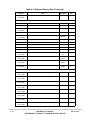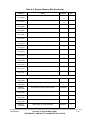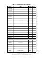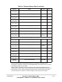
1
Signals
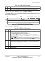
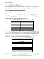
28.4.2.2 Port QB Digital I/O Pins
Port QB pins are referred to as PQB[3:0] when used as a 4-bit digital input/output port. In
addition to functioning as analog input pins, the port QB pins are also connected to the input
of a synchronizer during reads and may be used as general-purpose digital inputs when the
applied voltages meet VIH and VIL requirements.
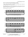
Each port QB pin is configured as an input or output by programming the Port Data
Direction Register (DDRQB). The digital input signal states are read from the port QB Data
Register (PORTQB) when DDRQB specifies that the pins are inputs. The digital data in
PORTQB is driven onto the port QB pins when the corresponding bits in DDRQB specify
output. See Section 28.6.4.
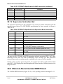
28.4.3 External Trigger Input Pins
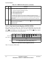
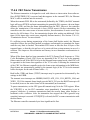
The QADC has two external trigger pins, ETRIG2 and ETRIG1. Each external trigger input
is associated with one of the scan queues, queue 1 or queue 2. The assignment of
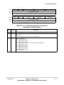
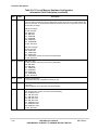
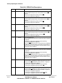
ETRIG[2:1] to a queue is made by the TRG bit in QADC Control Register 0 (QACR0).
When TRG = 0, ETRIG1 triggers queue 1 and ETRIG2 triggers queue 2. When TRG = 1,
ETRIG1 triggers queue 2 and ETRIG2 triggers queue 1. See Section 28.6.5 “Control
Registers.”
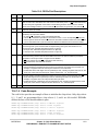
28.4.4 Multiplexed Address Output Pins
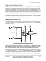
In non-multiplexed mode, the QADC analog input pins are connected to an internal
multiplexer which routes the analog signals into the internal A/D converter.
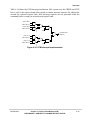
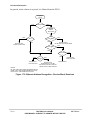
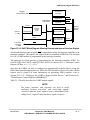
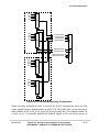
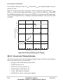
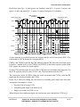
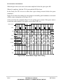
In externally multiplexed mode, the QADC allows automatic channel selection through up
to four external 4-to-1 multiplexer chips. The QADC provides a 2-bit multiplexed address
output to the external multiplexer chips to allow selection of one of four inputs. The
multiplexed address output signals, MA1 and MA0, can be used as multiplexed address
output bits or as general-purpose I/O when external multiplexed mode is not being used.
MA[1:0] are used as the address inputs for up to four 4-channel multiplexer chips. Because
the MA[1:0] pins are digital outputs in multiplexed mode, the state of their corresponding
data direction bits in DDRQA is ignored.
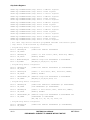
28.4.5 Multiplexed Analog Input Pins
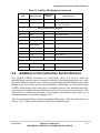
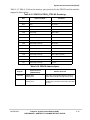
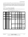
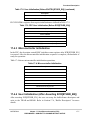
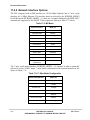
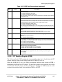
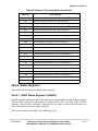
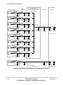
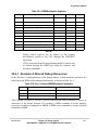
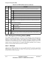
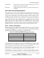
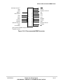
In external multiplexed mode, four of the port QB pins are redefined so that each represent
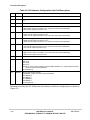
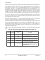
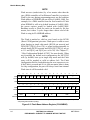
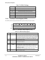
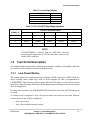
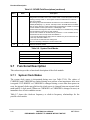
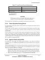
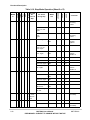
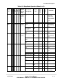
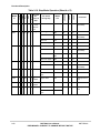
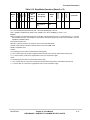
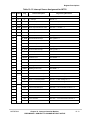
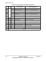
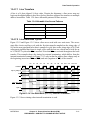
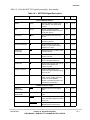
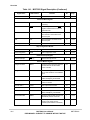
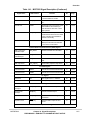
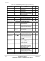
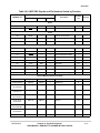
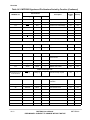
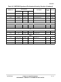
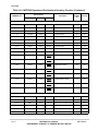
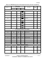
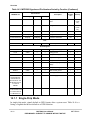
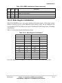
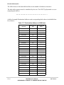
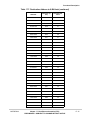
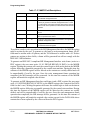
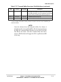
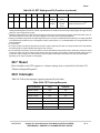
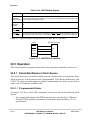
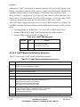
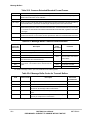
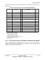
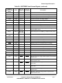
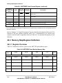
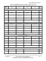
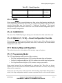
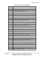
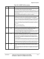
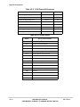
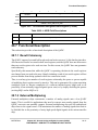
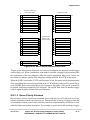
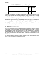
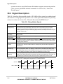
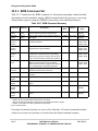
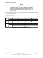
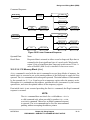
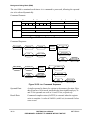
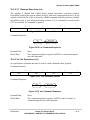
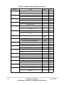
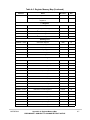
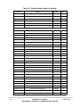
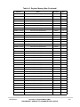
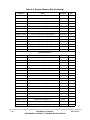
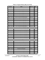
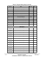
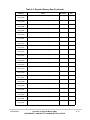
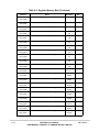
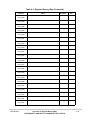
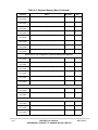
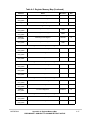
four analog input channels. See Table 28-1.
28-6
MCF5282 User’s Manual
PRELIMINARY—SUBJECT TO CHANGE WITHOUT NOTICE
MOTOROLA