1
19
page
EasyPIC6 Development System
14.0. Keypads
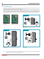
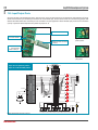
There are two keypads provided on the EasyPIC6 development system. These are keypad 4x4 and keypad MENU. Keypad 4x4 is a standard
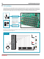
alphanumeric keypad connected to the microcontroller PORTD. The performance of such a keypad is based on the ‘scan and sense’ principle
ZKHUHWKH5'5'5'DQG5'SLQVDUHFRQ¿JXUHGDVLQSXWVFRQQHFWHGWRSXOOGRZQUHVLVWRUV7KH5'5'5'DQG5'SLQVDUH
FRQ¿JXUHGDVKLJKOHYHOYROWDJHRXWSXWV3UHVVLQJDQ\EXWWRQZLOOFDXVHDORJLFRQHWREHDSSOLHGWRLQSXWSLQV3XVKEXWWRQGHWHFWLRQLV
performed from within software. For example, pressing button ‘6’ will cause a logic one (1) to appear on the RD2 pin. In order to determine
which of the push buttons is pressed, a logic one (1) is applied to each of the following output pins RD4, RD5, RD6 and RD7.
Keypad MENU buttons are connected in a similar way to the PORTA buttons. The only difference is in the button arrangement. The keypad
MENU buttons are arranged so as to provide easy navigation through menus.
VCC-MCU
RN4
8x10K
J17
J4
SW4
BAT43
RD0
RD1
RD2
RD3
RD4
RD5
RD6
RD7
A
R59
R60
R61
R62
T46
T54
T50
T38
T43
T47
T56
T51
T57
D9
T59
T58
T39
T44
T48
T52
T40
T45
T49
T53
D10
220R
RD7
T42
T55
220R
RD6
D8
220R
RD5
T37
R58
220R
D11
RA5
RD4
RA2
VCCMCU
J24
Side view
K
RA0
22pF
RB7
RB6
RB5
RB4
RB3
RB2
RB1
RB0
VCC
GND
RD7
RD6
RD5
RD4
RC7
RC6
RC5
RC4
RD3
RD2
RA3
22pF
C7
)LJXUHKeypad MENU
RA1
C6
RA4
X1
8MHz
VCC-MCU
MCLR
RA0
RA1
RA2
RA3
RA4
RA5
RE0
RE1
RE2
VCC
GND
OSC1
OSC2
RC0
RC1
RC2
RC3
RD0
RD1
PICxxxx
VCC-MCU
)LJXUHKeypad 4x4 performance
)LJXUHKeypad 4x4
Jumper J17 is
in the pull-up
position. Pins
5'5'
RD2 and RD3
are connected
to pull-down
resistors through
DIP switch SW4
RD3
RD2
RD1
RD0
220R
DIP40
Figure 14-4: Keypads (4x4 and MENU) and microcontroller connection schematic
MikroElektronika