1
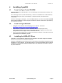
eCOG1X Low Cost Development Kit
Version 1.1
Cyan Technology
eCOG1X Low Cost Development Kit
User Manual
V1.1
27 June 2008
eCOG16E01 User Manual
Version 0.1
Confidential and Proprietary Information
© Cyan Technology Ltd., 2008
This document contains confidential and proprietary information of Cyan Technology Ltd. and is
protected by copyright laws. Its receipt or possession does not convey any rights to reproduce,
manufacture, use or sell anything based on information contained within this document.
Cyan TechnologyTM, the Cyan Technology logo and Max-eICETM are trademarks of Cyan
Holdings Ltd. CyanIDE® and eCOG® are registered trademarks of Cyan Holdings Ltd. Cyan
Technology Ltd. recognises other brand and product names as trademarks or registered
trademarks of their respective holders.
Any product described in this document is subject to continuous developments and
improvements. All particulars of the product and its use contained in this document are given by
Cyan Technology Ltd. in good faith. However, all warranties implied or expressed, including but
not limited to implied warranties of merchantability, or fitness for purpose, are excluded.
This document is intended only to assist the reader in the use of the product. Cyan Technology
Ltd. shall not be liable for any loss or damage arising from the use of any information in this
guide, any error or omission in such information, or any incorrect use of the product.
This product is not designed or intended to be used for on-line control of aircraft, aircraft
navigation or communications systems or in air traffic control applications or in the design,
construction, operation or maintenance of any nuclear facility, or for any medical use related to
either life support equipment or any other life-critical application. Cyan Technology Ltd.
specifically disclaims any express or implied warranty of fitness for any or all of such uses. Ask
your sales representative for details.
27 June 2008
Cyan Technology Ltd
Page i
eCOG16E01 User Manual
Version 0.1
Revision History
Version
Date
Notes
V1.0
22/01/2008
First release.
V1.1
27/06/2008
Corrected J3 connections in table 4.
27 June 2008
Cyan Technology Ltd
Page ii
eCOG16E01 User Manual
Version 0.1
Contents
List of Tables. . . . . . . . . . . . . . . . . . . . . . . . . . . . . . . . . . . . . . . . . . . . . . . . . v
1
Introduction . . . . . . . . . . . . . . . . . . . . . . . . . . . . . . . . . . . . . . . . . . . . 1
1.1
1.2
1.3
1.4
2
Development Kit Contents. . . . . . . . . . . . . . . . . . . . . . . . . . . . . . . . . . . . 1
Requirements . . . . . . . . . . . . . . . . . . . . . . . . . . . . . . . . . . . . . . . . . . . . . 1
Additional Documents . . . . . . . . . . . . . . . . . . . . . . . . . . . . . . . . . . . . . . . 1
Part Identification. . . . . . . . . . . . . . . . . . . . . . . . . . . . . . . . . . . . . . . . . . . 1
Quick Start . . . . . . . . . . . . . . . . . . . . . . . . . . . . . . . . . . . . . . . . . . . . . 2
2.1
2.2
2.3
3
Set Up System. . . . . . . . . . . . . . . . . . . . . . . . . . . . . . . . . . . . . . . . . . . . . 2
Copy the Example Projects . . . . . . . . . . . . . . . . . . . . . . . . . . . . . . . . . . . 2
Running an Example Project . . . . . . . . . . . . . . . . . . . . . . . . . . . . . . . . . . 2
Software . . . . . . . . . . . . . . . . . . . . . . . . . . . . . . . . . . . . . . . . . . . . . . . 3
3.1
3.2
4
CyanIDE . . . . . . . . . . . . . . . . . . . . . . . . . . . . . . . . . . . . . . . . . . . . . . . . . 3
USB eICE Drivers . . . . . . . . . . . . . . . . . . . . . . . . . . . . . . . . . . . . . . . . . . 3
Installing CyanIDE . . . . . . . . . . . . . . . . . . . . . . . . . . . . . . . . . . . . . . . 4
4.1
4.2
4.3
5
From the Cyan Tools CD-ROM . . . . . . . . . . . . . . . . . . . . . . . . . . . . . . . . 4
From the Cyan Website. . . . . . . . . . . . . . . . . . . . . . . . . . . . . . . . . . . . . . 4
Installing the USB eICE Driver . . . . . . . . . . . . . . . . . . . . . . . . . . . . . . . . 4
CyanIDE Examples . . . . . . . . . . . . . . . . . . . . . . . . . . . . . . . . . . . . . . 5
5.1
5.2
5.3
5.4
5.5
5.6
5.7
6
Development Board Examples . . . . . . . . . . . . . . . . . . . . . . . . . . . . . . . . 5
Serial Port Configuration . . . . . . . . . . . . . . . . . . . . . . . . . . . . . . . . . . . . . 5
Analogue Examples. . . . . . . . . . . . . . . . . . . . . . . . . . . . . . . . . . . . . . . . . 6
General Examples . . . . . . . . . . . . . . . . . . . . . . . . . . . . . . . . . . . . . . . . . . 6
GPIO Examples. . . . . . . . . . . . . . . . . . . . . . . . . . . . . . . . . . . . . . . . . . . . 7
Serial Examples. . . . . . . . . . . . . . . . . . . . . . . . . . . . . . . . . . . . . . . . . . . . 7
Simulator Examples. . . . . . . . . . . . . . . . . . . . . . . . . . . . . . . . . . . . . . . . . 8
Development Board . . . . . . . . . . . . . . . . . . . . . . . . . . . . . . . . . . . . . . 9
6.1
6.2
7
Overview . . . . . . . . . . . . . . . . . . . . . . . . . . . . . . . . . . . . . . . . . . . . . . . . . 9
Description. . . . . . . . . . . . . . . . . . . . . . . . . . . . . . . . . . . . . . . . . . . . . . . . 9
eCOG1X USB eICE Adaptor . . . . . . . . . . . . . . . . . . . . . . . . . . . . . . 10
7.1
7.2
8
Overview . . . . . . . . . . . . . . . . . . . . . . . . . . . . . . . . . . . . . . . . . . . . . . . . 10
Description. . . . . . . . . . . . . . . . . . . . . . . . . . . . . . . . . . . . . . . . . . . . . . . 10
Peripheral Functions and Connections . . . . . . . . . . . . . . . . . . . . . . 11
8.1
8.2
8.3
8.4
8.5
8.6
8.7
8.8
Power Supply . . . . . . . . . . . . . . . . . . . . . . . . . . . . . . . . . . . . . . . . . . . . 11
eICE Debug Port . . . . . . . . . . . . . . . . . . . . . . . . . . . . . . . . . . . . . . . . . . 11
Serial Ports . . . . . . . . . . . . . . . . . . . . . . . . . . . . . . . . . . . . . . . . . . . . . . 11
Analogue Inputs. . . . . . . . . . . . . . . . . . . . . . . . . . . . . . . . . . . . . . . . . . . 11
I2C . . . . . . . . . . . . . . . . . . . . . . . . . . . . . . . . . . . . . . . . . . . . . . . . . . . . . 11
SPI. . . . . . . . . . . . . . . . . . . . . . . . . . . . . . . . . . . . . . . . . . . . . . . . . . . . . 11
Timers and Counters . . . . . . . . . . . . . . . . . . . . . . . . . . . . . . . . . . . . . . . 11
Input/Output Connections . . . . . . . . . . . . . . . . . . . . . . . . . . . . . . . . . . . 12
Appendix A Important Notes . . . . . . . . . . . . . . . . . . . . . . . . . . . . . . . . . . . 14
27 June 2008
Cyan Technology Ltd
Page iii
eCOG16E01 User Manual
Version 0.1
Appendix B Circuit Diagram . . . . . . . . . . . . . . . . . . . . . . . . . . . . . . . . . . . . 15
Appendix C Board Layout . . . . . . . . . . . . . . . . . . . . . . . . . . . . . . . . . . . . . 17
27 June 2008
Cyan Technology Ltd
Page iv
eCOG16E01 User Manual
Version 0.1
List of Tables
1:
2:
3:
4:
5:
27 June 2008
S1: eICE connections . . . . . . . . . . . . . . . . . . . . . . . . . . . . . . . . . . . . . . 11
J1 connections. . . . . . . . . . . . . . . . . . . . . . . . . . . . . . . . . . . . . . . . . . . . 12
J2 connections. . . . . . . . . . . . . . . . . . . . . . . . . . . . . . . . . . . . . . . . . . . . 12
J3 connections. . . . . . . . . . . . . . . . . . . . . . . . . . . . . . . . . . . . . . . . . . . . 13
J4 connections. . . . . . . . . . . . . . . . . . . . . . . . . . . . . . . . . . . . . . . . . . . . 13
Cyan Technology Ltd
Page v
eCOG16E01 User Manual
1
Version 0.1
Introduction
This document describes the eCOG16E01 User Manual.
1.1
Development Kit Contents
•
Low cost development board, fitted with an eCOG1X1A5 or an eCOG1XE01A6 device.
•
Cyan eCOG1X USB eICE adaptor
•
USB cable (A to mini-B)
•
CD-ROM containing CyanIDE development software and documentation
1.2
Requirements
•
A Windows-based PC system.
(minimum 1GHz CPU speed, higher speed recommended).
•
Windows 2000 or Windows XP operating system.
•
100MB free disk space.
•
512MB memory (1GB recommended).
•
A spare USB port.
•
A spare serial port (optional).
•
System administrator privileges are required for software installation.
1.3
1.4
Additional Documents
1.
eCOG1X or eCOG1XE01 User Manual
2.
CyanIDE User Manual
3.
eCOG1X USB eICE Programming Adaptor User Manual
Part Identification
In this document, any reference to eCOG1 means the generic chip and is applicable to all
versions. All eCOG1 devices are suffixed according to their version; any reference to a
particular version such as eCOG1XE01A6 is specific to that version.
27 June 2008
Cyan Technology Ltd
Page 1
eCOG16E01 User Manual
2
Version 0.1
Quick Start
Please also read Appendix A Important Notes.
2.1
Set Up System
•
Unpack and check contents of kit.
•
Install CyanIDE V1.4.3 or later development software and USB device drivers.
See section 4 Installing CyanIDE for more details.
•
Connect the Cyan eCOG1X USB eICE adaptor to socket S1 on the development board.
•
Connect the USB cable between the eICE adaptor and the host PC.
2.2
Copy the Example Projects
CyanIDE includes a range of example projects for the development kits, copied during
installation into the <examples> directory under the CyanIDE install directory, usually
<C:\Program FIles\Cyan Technology\CyanIDE>. The installation process also creates a
<CyanIDE Projects> directory in the user’s My Documents folder.
The eCOG1X low cost development board is described in CyanIDE as the eCOG1XE01
development board. It is recommended that the examples for this board are copied from the
the <examples\eCOG1XE01 dev board> directory into the user’s projects directory before
use, to avoid making any changes to the original examples.
•
Open the My Documents directory and browse into the CyanIDE Projects directory. This
includes a shortcut to the CyanIDE examples directory.
•
Open the <CyanIDE Examples> shortcut and then the <eCOG1XE01 dev board>
directory.
•
Type ctrl-A or click Edit->Select All to select all the eCOG1XE01 example projects,
then type ctrl-C or click Edit->Copy to copy them to the clipboard.
•
Click the Back button twice to return to the CyanIDE Projects directory.
•
Type ctrl-V or click Edit->Paste to paste the example projects from the clipboard into
the current directory.
2.3
Running an Example Project
As an introduction, try the FlashLEDs example project located in the GPIO\FlashLEDs
directory.
•
Start CyanIDE.
•
From the main menu, select Project->Open and browse to the LCD example directory
<CyanIDE Projects\GPIO\FlashLEDs>. Select the project file <*.cyp> and click Open.
CyanIDE loads the project and displays the files included in the project in the navigator
pane at the left of the main window.
•
Select Build->Rebuild All from the main menu. This compiles the project source files
and links the object code into a download image file.
•
Select Debug->Run. CyanIDE connects to the target processor on the development
board, downloads the application code and begins execution.
27 June 2008
Cyan Technology Ltd
Page 2
eCOG16E01 User Manual
3
3.1
Version 0.1
Software
CyanIDE
The CyanIDE V1.4.3 or later software development package supports the eCOG1X family of
microcontrollers, providing project management, source code editor, C compiler, assembler,
linker, source level debugger, and online help files. It is available on CD-ROM, or as a
download to registered users on the Cyan web site at www.cyantechnology.com.
CyanIDE communicates with the eCOG1X microcontroller on the target system via the eICE
debug port. The host PC requires a simple eICE adaptor that connects to the 10-way header
P3 on the development board. The development kit includes the Cyan eCOG1X USB eICE
adaptor.
CyanIDE includes a range of example applications for the various development boards.
These can provide a good starting point for customer applications, or just as examples
showing how to set up a software project. Further application examples including CyanIDE
project files with source code are available on the web site support pages.
3.2
USB eICE Drivers
The software drivers for the eCOG1X USB eICE adaptor are included in the CyanIDE
development package. CyanIDE V1.4.3 or later includes the required version of the driver
files as standard.
To ensure that the driver files are present, install the CyanIDE software and any necessary
updates before connecting the eICE adaptor to the host PC. Further details about the
software installation are shown later in this document.
Note that any previous version of CyanIDE should be uninstalled before the latest version is
installed. This includes any USB device drivers for Cyan products such as the evaluation
board, which should be removed via the Device Manager. Installing the new version of
CyanIDE also reinstalls the USB eICE device driver.
27 June 2008
Cyan Technology Ltd
Page 3
eCOG16E01 User Manual
4
Version 0.1
Installing CyanIDE
4.1
From the Cyan Tools CD-ROM
Insert the CD into the CD-ROM drive. The html start page should load automatically in the
default browser.
If the start page does not load automatically, or Autorun is disabled for the CD-ROM drive,
then Browse the Cyan CD in a file manager or explorer window, and open the file
<index.htm>.
When the start page is displayed, click on the Menu button, then select the Install CyanIDE
item to begin installation of the development software. Follow the instructions presented by
the installation program.
4.2
4.3
From the Cyan Website
•
Navigate to the software downloads page on the website, located at
http://www.cyantechnology.com/support/updates.php.
•
Download the CyanIDE full version installation file to a temporary directory.
Please note that users must log in to the website with their registered account name
and password for the support forum to download this file.
•
Execute the downloaded file to install the development software. Follow the instructions
presented by the installation program.
Installing the USB eICE Driver
CyanIDE V1.4.3 includes the driver files for the eCOG1X USB eICE adaptor as standard,
and it is not necessary to install them separately.
When an eICE adaptor is connected to a PC for the first time, the USB enumeration process
identifies it as new hardware, and Windows starts the Found New Hardware process. Driver
installation under Windows 2000 and Windows XP is fully automatic and does not require
any user interaction.
27 June 2008
Cyan Technology Ltd
Page 4
eCOG16E01 User Manual
5
Version 0.1
CyanIDE Examples
CyanIDE includes a number of example software projects, pre-configured for use with the
eCOG1X development boards, the eCOG1k development and evaluation boards, or the
eCOG1 simulator. The examples for the eCOG1X low cost development board are
described briefly in the table below.
5.1
Development Board Examples
The following example applications for the eCOG1X low cost development board
(eCOG1XE01 development board) are included as standard with CyanIDE V1.4.3.
5.2
Example
Comments
Analogue
Examples showing the use of the analogue peripheral
CounterTrigger
Using the CNT1 counter to trigger ADC conversions
SoftwareTrigger
Triggering ADC conversions in software
General
General purpose examples
Timers
Shows the use of all the eCOG1X timers
GPIO
Examples using the GPIO connections
FlashLEDs
Flashes LEDs in sequence on the development board
Serial
Serial port example
DuartEcho
Echoes received characters on UART1A
Serial Port Configuration
Many examples use one of the serial ports to report results or display messages. Use a
terminal program such as 'HyperTerminal' to communicate with the application. The default
serial port configuration is shown below.
•
9600 Baud
•
8 data bits
•
no parity bits
•
one stop bit
•
no flow control
27 June 2008
Cyan Technology Ltd
Page 5
eCOG16E01 User Manual
5.3
Analogue Examples
5.3.1
Counter Trigger
Version 0.1
This example uses CNT1 to trigger ADC conversions. This is performed in the background
while the application waits for the user to press a key (a blocking operation). It uses
UART1A to output text to a terminal and receive keyboard input.
File
Comments
CounterTrigger-eCOG1XE01A.cyp
CyanIDE project file
cstartup.asm
C environment initialisation
pack.asm
C const and init data segments
eCOG1XE01A.cfg
Peripheral configuration file
internal.map
Memory map
main.c
Application code
5.3.2
Software Trigger
This example performs ADC conversions by triggering the conversion from software. It uses
UART1A to output text to a terminal.
File
Comments
SoftwareTrigger-eCOG1XE01A.cyp
CyanIDE project file
cstartup.asm
C environment initialisation
pack.asm
C const and init data segments
eCOG1XE01A.cfg
Peripheral configuration file
internal.map
Memory map
main.c
Application code
5.4
General Examples
5.4.1
Timers
This example demonstrates the use of the timers available in the eCOG1X. It uses UART1A
to output text to a terminal.
File
Comments
Timers-eCOG1XE01A.cyp
CyanIDE project file
cstartup.asm
C environment initialisation
pack.asm
C const and init data segments
eCOG1XE01A.cfg
Peripheral configuration file
internal.map
Memory map
main.c
Application code
27 June 2008
Cyan Technology Ltd
Page 6
eCOG16E01 User Manual
5.5
GPIO Examples
5.5.1
Flash LEDs
Version 0.1
This application flashes the LEDs on the development board in sequence. It uses UART1A
to output text to a terminal.
File
Comments
FlashLEDs-eCOG1XE01A.cyp
CyanIDE project file
cstartup.asm
C environment initialisation
pack.asm
C const and init data segments
eCOG1XE01A.cfg
Peripheral configuration file
internal.map
Memory map
main.c
Application code
5.6
Serial Examples
5.6.1
DUART Echo
This example echoes back out any incoming characters from the UART1A serial port. It
uses the serial_lib routines to provide circular buffering and interrupt support.
File
Comments
DuartEcho-eCOG1XE01A.cyp
CyanIDE project file
cstartup.asm
C environment initialisation
pack.asm
C const and init data segments
eCOG1XE01A.cfg
Peripheral configuration file
internal.map
Memory map
main.c
Application code
27 June 2008
Cyan Technology Ltd
Page 7
eCOG16E01 User Manual
5.7
Version 0.1
Simulator Examples
The following example simulator applications are also included with CyanIDE. They can be
found in the <examples\simulator> directory located below the CyanIDE installation
directory.
Example
Comments
primes
Searches for prime numbers
oscillator
Example of using a simulated memory-mapped device
5.7.1
primes
The 'primes' application searches for prime numbers and displays results in the Debug
Output Window. The results are displayed using an implementation of putchar() that
includes the assembler PRINT instruction. The simulator interprets this instruction according
to the Print mode option in Project Properties: printing a character, a hexadecimal value, or
raising an exception.
File
Comments
primes.cyp
CyanIDE project file
cstartup.asm
C environment initialisation
pack.asm
C const and init data segments
irq.asm
Entry point and interrupt vectors
primes.c
Application code
putchar.c
Character output routine
simulator.map
Memory map
5.7.2
oscillator
The 'oscillator' application reads a simulated ADC which is generating data representing a
sine wave, and writes a filtered value back to a memory location. The filtered value is logged
to a file.
File
Comments
oscillator.cyp
CyanIDE project file
cstartup.asm
C environment initialisation
pack.asm
C const and init data segments
irq.asm
Entry point and interrupt vectors
oscillator.c
Application code
putchar.c
Character output routine
oscillator.py
Simulated ADC written in Python.
The Run on project load option for this file is set.
simulator.map
Memory map - includes CUSTOM entry
27 June 2008
Cyan Technology Ltd
Page 8
eCOG16E01 User Manual
6
Version 0.1
Development Board
6.1
Overview
Figure 1: eCOG1X low cost development board
The eCOG1X low cost development board has the following major features.
6.2
•
eCOG1X1A5 microcontroller with 512Kbytes flash memory and 24Kbytes SRAM
or
eCOG1XE01A6 microcontroller with 64Kbytes flash memory and 8Kbytes SRAM.
•
10 way right angle socket for the eICE debug port (S1).
•
Four serial ports, two with optional EIA/TIA-562 transceiver.
•
Four 12-bit analogue inputs.
•
Two user/status LEDs.
•
Hardware reset pushbutton.
•
Free pads or pin headers for input and output port connections.
•
Powered from the eICE adaptor or from an external 5V d.c. power supply.
Description
The eCOG1X microcontroller has a 16-bit CPU architecture and a wide range of on-chip
peripherals. It operates at clock speeds of up to 70MHz internally from an 8MHz crystal or
32.768kHz watch crystal. Refer to the eCOG1X User Manual for further details.
The board is fitted with a 10-way right angle socket (S1) for the eICE debug port. This port
connects directly to the processor core, and is used for downloading and debugging
applications code. A Cyan USB eICE adaptor is supplied with the Development Board,
although any external eICE adaptor may be used. The eICE adaptor connects directly to
socket S1.
Four serial ports are available on the Development Board. Two of these may be buffered by
an external LTC1386CS transceiver device. The unbuffered serial port signals (3.3V) are
available on header J1, and the buffered EIA/TIA-562 level signals are available on
header J3.
Four 12-bit analogue inputs on the eCOG1X device are available on header J2.
The Development Board can be powered from an external 5V d.c. power supply, connected
via header J4, or from the USB 5V via the eICE debug connection on S1.
27 June 2008
Cyan Technology Ltd
Page 9
eCOG16E01 User Manual
7
Version 0.1
eCOG1X USB eICE Adaptor
7.1
Overview
The USB eICE adaptor provides a connection from the host PC to the target eCOG1 family
device. A number of different eICE adaptors are available from Cyan Technology. The
device driver software for the host PC is included in the CyanIDE installation.
Figure 2: eCOG1X USB eICE adaptor
The Cyan eCOG1X USB eICE adaptor has the following major features.
7.2
•
Cyan eCOG1X5A5 device providing USB interface to host PC.
•
Local control of eICE debug interface transactions gives higher performance.
•
USB mini-B socket.
•
USB cable (A to mini-B) for host PC connection.
•
10 way boxed header for eICE debug port.
•
Powered from USB +5V supply.
•
5V supply connection available for low-power target systems.
Description
This adaptor uses the Cyan eCOG1X5A5 device to implement the USB interface to the host
PC system. A standard USB cable connects to the host side of the unit via a mini-B USB
socket. The PC end of the cable has a type A USB connector fitted. The eICE connection to
the eCOG1X1A5 or eCOG1XE01 target device is via a 10 way boxed header that connects
directly into the 10 way socket on the development board. The eCOG1X5A5 device provides
the USB interface to the host PC and digital inputs and outputs for the eICE signals.
Configuration data including serial numbers, USB PID and VID numbers, and identifier
strings is stored in the eCOG1X internal flash memory. This configuration data is required to
allow the unit to identify itself to the host PC during the USB device enumeration process,
and for the PC then to select the correct device driver files. The Cyan USB eICE adaptors
are loaded with the required configuration data during functional test.
The adaptor is powered from the +5V supply available on the host USB connection. Local
on-board regulators provide 3.3V and 1.8V for the eCOG1X device, and for the I/O
connections to the target eCOG1X device.
All signals to the target device eICE conection include 100Ω series resistors. The LOADB
signal also includes a 1kΩ pull-up resistor. The USB +5V supply is also connected to the
10 way header; this may be used to power small target systems provided the total current
drawn is within the 500mA limit available from a standard USB host.
27 June 2008
Cyan Technology Ltd
Page 10
eCOG16E01 User Manual
8
Version 0.1
Peripheral Functions and Connections
8.1
Power Supply
The eCOG1X low cost development board can be powered from an external 5V d.c. supply
via header J4, or from the USB 5V via the eICE adaptor connection on socket S1. The 5V
power supply input is regulated down by two low dropout regulators to provide the 3.3V and
1.8V power supplies for the eCOG1X device.
8.2
eICE Debug Port
The pin connections for the eICE signals on the 10 way right angle socket S1 are shown in
the table below.
Pin Name
Description
1
eICE_MOSI
Master Out Slave In, input from the eICE adaptor.
2
VDD_EICE
5V power supply input from the eICE adaptor.
3
NC
No connection.
4
GND
5
eICE_LOADB
6
GND
7
eICE_CLOCK
8
GND
9
eICE_MISO
Master In Slave Out, output to the eICE adaptor.
10
eICE_nRESET
Active low reset, connected in parallel with the reset switch.
eICE LoadB signal, open-collector, bidirectional.
eICE serial clock, input from the eICE adaptor.
Table 1: S1: eICE connections
The Cyan USB eICE adaptor provides 5V d.c. on the VDD_EICE pin, from the USB hub on
the host PC.
8.3
Serial Ports
Four UART serial ports are available. The unbuffered serial port signals are provided on
header J1. Two of the serial ports may be buffered to EIA/TIA-562 levels by an external
LTC1386CS transceiver device. The buffered signals for these two serial ports are provided
on header J3.
8.4
Analogue Inputs
Connections to four analogue inputs on the eCOG1X on-chip 12-bit analogue-to-digital
converter are provided on header J2.
8.5
I2C
The eCOG1X processor on the development board has an I2C compatible serial port. The
I2C SCL and SDA signals are available on header J1.
8.6
SPI
The eCOG1X processor has an SPI compatible serial port, using a standard four wire
connection. The SPI SCLK, MOSI, MISO and CS signals are available on header J2.
8.7
Timers and Counters
The eCOG1X device has a total of five general-purpose timers and counters available. Four
timer/counter input and output signals are available on header J2.
27 June 2008
Cyan Technology Ltd
Page 11
eCOG16E01 User Manual
8.8
Input/Output Connections
8.8.1
J1
Pin
Name
Description
1
+3.3V
+3.3V supply
2
+3.3V
+3.3V supply
3
I2C_SCL
4
5
6
7
8
9
10
11
Version 0.1
Port
Function
I2C serial clock
PortD_0
I2C_SCL
I2C_SDA
I2C serial data
PortD_1
I2C_SDA
UART0_TX
Transmit data output
PortA_0
UART1A_TX
UART0_RX Receive data input
PortA_1
UART1A_RX
UART1_TX
PortA_2
UART1B_TX
UART1_RX Receive data input
PortA_3
UART1B_RX
UART2_TX
PortA_4
UART2A_TX
UART2_RX Receive data input
PortA_5
UART2A_RX
UART3_TX
PortA_6
UART2B_TX
Transmit data output
Transmit data output
Transmit data output
12
UART3_RX Receive data input
PortA_7
UART2B_RX
13
LED1
PortB_0
GPIOB_0
14
LED2
PortB_1
GPIOB_1
15
GND
0V supply
16
GND
0V supply
Table 2: J1 connections
8.8.2
J2
Pin
Name
Description
1
+3.3V
+3.3V supply
Port
2
+3.3V
+3.3V supply
3
ADC_Vin1
Analogue input 1
ADC1_Vin2
4
ADC_Vin2
Analogue input 2
ADC1_Vin3
5
ADC_Vin3
Analogue input 3
ADC2_Vin2
6
ADC_Vin4
Analogue input 4
ADC2_Vin3
7
UCT0
Counter clock input
Capture timer input
PortT_0
CNT1/CAP1
8
UCT1
Counter clock input
Capture timer input
PortT_1
CNT2/CAP2
9
UCT2
PWM timer output
Capture timer input
PortT_2
PWM1/CAP1
10
UCT3
PWM timer output
Capture timer input
PortT_3
PWM2/CAP2
11
SPI_SCLK
SPI serial clock
PortE_0
ESPI_SCLK
12
SPI_MOSI
SPI master out slave in PortE_1
ESPI_MOSI
13
SPI_MISO
SPI master in slave out PortE_2
ESPI_MISO
14
SPI_CS
SPI chip select
ESPI_CS
15
GND
0V supply
16
GND
0V supply
PortE_3
Function
Table 3: J2 connections
27 June 2008
Cyan Technology Ltd
Page 12
eCOG16E01 User Manual
8.8.3
Version 0.1
J3: Buffered Serial Ports
Pin
Name
Description
1
GND
0V supply
Port
Function
2
3
UART1_RX Receive data input
PortA_3
UART1B_RX
UART1_TX
PortA_2
UART1B_TX
4
5
UART0_RX Receive data input
PortA_1
UART1A_RX
UART0_TX
Transmit data output
PortA_0
UART1A_TX
6
GND
0V supply
Transmit data output
Table 4: J3 connections
8.8.4
J4: Power
Pin
Name
Description
Notes
1
PWR
+5V supply
Square pad next to J4 label
2
GND
0V supply
Round pad
Table 5: J4 connections
27 June 2008
Cyan Technology Ltd
Page 13
eCOG16E01 User Manual
Appendix A
Version 0.1
Important Notes
The following recommendations should be observed when using the USB eICE adaptor.
•
Connect the USB cable from the eICE adaptor directly to the host PC, not via an
external hub. CyanIDE can fail to restart the eICE debug connection after any errors if
the USB device is connected via an external hub.
•
The memory window in CyanIDE can be quite slow to refresh across the USB eICE link.
Close the memory window when it is not required to improve the speed of response to
commands.
•
Do not disconnect the USB eICE cable or power down the target system while CyanIDE
is running. This can cause CyanIDE to hang up on the next attempt to connect to the
target system via eICE.
Ensure that CyanIDE is closed down before disconnecting the USB cable or powering
down the target system.
•
CyanIDE may report an error message on its first attempt to connect to the target
system via eICE. This occurs when it tries to find a connection to a target system on the
parallel port instead of the USB port. Repeat the command and CyanIDE should
connect to the USB eICE target system successfully.
If the debugger still does not start, check that power is present on the target system,
that all required jumper links are fitted, and that the USB cable is connected correctly to
the host PC.
27 June 2008
Cyan Technology Ltd
Page 14
eCOG16E01 User Manual
Appendix B
27 June 2008
Version 0.1
Circuit Diagram
Cyan Technology Ltd
Page 15
eCOG16E01 User Manual
27 June 2008
Cyan Technology Ltd
Version 0.1
Page 16
eCOG16E01 User Manual
Appendix C
27 June 2008
Version 0.1
Board Layout
Cyan Technology Ltd
Page 17