1
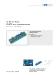
E-802 Servo-Control Submodule
User Manual PZ 113E
Table of Contents
0
Safety Precautions ........................................................... 3
1
Introduction....................................................................... 4
1.1
Functionality................................................................................. 4
1.2
Model Summary........................................................................... 5
2
E-802.55 ............................................................................. 6
2.1
Component Locations .................................................................. 6
2.2
Adjustment Controls..................................................................... 6
2.3
Block Diagram.............................................................................. 7
2.4
Notch Filter Settings..................................................................... 7
2.4.1
Range .......................................................................................... 7
2.4.2
Damping....................................................................................... 8
2.5
Voltage Ranges and Over-Voltage Recognition Settings ............ 8
2.6
Test Points ................................................................................... 9
2.7
Pinouts ....................................................................................... 10
2.8
Servo-Loop Calibration .............................................................. 11
2.8.1
Equipment Needed for Calibration............................................. 11
2.8.2
Preparations............................................................................... 11
2.8.3
Zero-Point Adjustment ............................................................... 12
2.8.4
Static Gain Adjustment .............................................................. 12
2.9
Dynamic Calibration................................................................... 13
2.9.1
Finding Resonant Frequency and Setting Notch Filter .............. 13
2.9.2
Step Response Optimization (Empirical Method) ...................... 13
2.9.3
Step-Response Optimization (Calculation Method) ................... 15
2.9.4
Sizing Components.................................................................... 16
2.9.5
Applying Calculated Values in the Circuit .................................. 16
3
E-802.50, E-802.51, E-802.52 .......................................... 17
3.1
E-802.50 Board Description....................................................... 17
3.1.1
Component Locations ................................................................ 17
3.1.2
Adjustment Controls................................................................... 17
3.1.3
Block Diagram............................................................................ 17
3.1.4
Notch Filter Setting .................................................................... 17
3.2
E-802.51 / E-802.52 Board Description ..................................... 18
3.2.1
Component Locations ................................................................ 18
3.2.2
Adjustment Controls................................................................... 18
3.2.3
Block Diagram............................................................................ 18
Release 1.4.0
www.pi.ws
Page 1