1
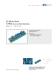
E-802 Servo-Control Submodule
User Manual PZ 113E
2.3 Block Diagram
P4 :
S1 :
S2 :
S e rv o
O FF
P1 : S le w
X1:
Ta rg e t
S le w R a te
L im ite r
P2 :
+
P3 : T im e
L o o p G a in
Se n so r
V a lu e
N o tc h
F ilte r
ON
se e
n o te
P5 : T im e
C o n tro l O u tp u t
(To A m p lifie r)
D rift
C o m p e n s.
O v e rflo w
D e te c tio n
+
In te g ra to r
+
P6 :
O n -Ta rg e t D e te c tio n
G a in F in e A d ju st
E-802.55 Block Diagram
Note: The servo ON-OFF “switch” is controlled by electrical signals from the board on which the
submodule is installed.
2.4 Notch Filter Settings
The frequencies within a frequency range can be set with potentiometer P4.
Alternate/extended frequency ranges are available with the mini DIP switches (S2)
as shown in the table below (contact PI for latest information on possible changes):
2.4.1
Range
Range
Number
1
Mini-DIP Switch Block S2
(switch slider shown in black)
ON
1
P4-Min. Notch
P4-Max. Notch
Frequency in Hz Frequency in Hz
8
40
130
120
380
340
1100
950
3100
2900
9300
OFF
2
ON
1
8
OFF
3
ON
1
8
OFF
4
ON
1
8
OFF
5* (all
switches
OFF)
ON
1
8
OFF
Release 1.4.0
www.pi.ws
Page 7