1
user manual
Version 1.70
Last update: May 2011
homeVisu Version: 1.1.18
Author: Peter Beck
Index
INTRODUCTION ................................................................................ 9
Software installation ................................................................................ 10
Windows .................................................................................................. 10
Linux / Ubuntu 10.04 ................................................................................. 10
Connection PLC-BUS interface or other RS232 devices............................. 11
1. connection of the PLC-BUS interface directly to the PC ............................... 11
2. connecting the PLC BUS interface through a RS232 port server ................... 11
Set interface connection........................................................................... 12
homeVisu as Java applet und browser ..................................................... 12
THE USER INTERFACE ..................................................................... 13
The tab area ............................................................................................. 15
The context menu of the tab pane ............................................................ 16
new tab.................................................................................................... 16
side panel................................................................................................. 16
start macro............................................................................................... 16
size and position ....................................................................................... 17
undo ........................................................................................................ 17
redo......................................................................................................... 17
save ........................................................................................................ 17
all visible .................................................................................................. 17
HV1, HV2, HVxx ........................................................................................ 18
setup ....................................................................................................... 18
info.......................................................................................................... 18
THE SETUP ...................................................................................... 19
Setup password........................................................................................ 20
Operating mode........................................................................................ 21
Frame setup ............................................................................................. 22
Panel setup .............................................................................................. 23
Server setup............................................................................................. 24
Multi user ................................................................................................. 25
INI files.................................................................................................... 26
© 2011 pbe - Peter Beck
page: 2 of 114
www.p-b-e.de
Active timer.............................................................................................. 27
Full screen mode ...................................................................................... 28
Look and Feel ........................................................................................... 29
Language ................................................................................................. 30
THE BASE PANELS........................................................................... 31
The context menu of the panels ............................................................... 32
name ....................................................................................................... 32
properties................................................................................................. 33
macro ...................................................................................................... 33
export ...................................................................................................... 33
import...................................................................................................... 33
paste ....................................................................................................... 33
invisible.................................................................................................... 34
delete ...................................................................................................... 34
size and position ....................................................................................... 34
group panel .............................................................................................. 34
macro button ............................................................................................ 34
status field ............................................................................................... 34
basic slider ............................................................................................... 34
other components ..................................................................................... 35
all visible .................................................................................................. 35
HVxx........................................................................................................ 35
new panel................................................................................................. 35
The properties of the panels..................................................................... 35
name ....................................................................................................... 35
font size ................................................................................................... 36
font style.................................................................................................. 36
background .............................................................................................. 36
color ........................................................................................................ 36
image file ................................................................................................. 36
style ........................................................................................................ 36
horizontal ................................................................................................. 36
vertical..................................................................................................... 37
frame....................................................................................................... 37
transparent............................................................................................... 37
THE COMPONENTS .......................................................................... 38
Size and position ...................................................................................... 38
with the mouse ......................................................................................... 38
auxiliary window “size and position"............................................................. 39
© 2011 pbe - Peter Beck
page: 3 of 114
www.p-b-e.de
THE GROUP PANEL .......................................................................... 39
The context menu of the group panel....................................................... 40
to foreground............................................................................................ 40
copy ........................................................................................................ 40
The properties of the group panel ............................................................ 40
show image .............................................................................................. 41
position .................................................................................................... 41
size ......................................................................................................... 41
THE MACRO BUTTON ....................................................................... 41
The context menu of the macro button .................................................... 42
button text ............................................................................................... 43
properties................................................................................................. 43
macro ...................................................................................................... 44
set status ................................................................................................. 44
timer ....................................................................................................... 45
export ...................................................................................................... 45
to foreground............................................................................................ 45
copy ........................................................................................................ 45
enable/disable........................................................................................... 46
invisible.................................................................................................... 46
delete ...................................................................................................... 46
The properties of the macro button .......................................................... 47
name ....................................................................................................... 47
font size ................................................................................................... 47
font style.................................................................................................. 48
font color.................................................................................................. 48
images ..................................................................................................... 48
button...................................................................................................... 48
over......................................................................................................... 49
pressed .................................................................................................... 49
disabled ................................................................................................... 49
style ........................................................................................................ 50
image text ................................................................................................ 50
frame....................................................................................................... 50
transparent............................................................................................... 50
show image .............................................................................................. 50
position .................................................................................................... 50
size ......................................................................................................... 50
The macro window ................................................................................... 51
create a macro.......................................................................................... 51
examples of macros ................................................................................... 53
load selection............................................................................................ 54
add.......................................................................................................... 54
© 2011 pbe - Peter Beck
page: 4 of 114
www.p-b-e.de
replace..................................................................................................... 54
del........................................................................................................... 54
up ........................................................................................................... 54
down ....................................................................................................... 54
close ........................................................................................................ 54
The event window .................................................................................... 55
create an event ......................................................................................... 55
examples of events.................................................................................... 57
event status.............................................................................................. 57
event function ........................................................................................... 57
load selection............................................................................................ 58
add.......................................................................................................... 58
replace..................................................................................................... 58
del........................................................................................................... 58
close ........................................................................................................ 58
The timer window .................................................................................... 59
the date timer ........................................................................................... 59
the periodically timer ................................................................................. 60
the weekly timer ....................................................................................... 60
timer function ........................................................................................... 61
now ......................................................................................................... 61
choose date .............................................................................................. 61
add timer ................................................................................................. 62
del timer .................................................................................................. 62
close ........................................................................................................ 62
THE STATUS FIELD.......................................................................... 63
The context menu of the status field ........................................................ 63
status text ................................................................................................ 63
properties................................................................................................. 64
set status ................................................................................................. 64
export ...................................................................................................... 65
to foreground............................................................................................ 65
copy ........................................................................................................ 65
invisible.................................................................................................... 65
delete ...................................................................................................... 65
The properties of the status field ............................................................. 66
test status ................................................................................................ 66
activate .................................................................................................... 66
value ....................................................................................................... 67
text ......................................................................................................... 67
font size ................................................................................................... 67
font style.................................................................................................. 67
text color.................................................................................................. 68
background color....................................................................................... 68
© 2011 pbe - Peter Beck
page: 5 of 114
www.p-b-e.de
images ..................................................................................................... 68
image file ................................................................................................. 68
style ........................................................................................................ 68
image text ................................................................................................ 68
frame....................................................................................................... 68
transparent............................................................................................... 69
show image .............................................................................................. 69
position .................................................................................................... 69
size ......................................................................................................... 69
The set status windows............................................................................ 69
setting the status listener ........................................................................... 70
set status ................................................................................................. 71
negation................................................................................................... 71
close ........................................................................................................ 71
THE MULTI STATUS FIELD............................................................... 72
THE BASIC SLIDER.......................................................................... 73
The context menu of the basic slider........................................................ 73
name ....................................................................................................... 73
properties................................................................................................. 74
set value .................................................................................................. 74
export ...................................................................................................... 75
to foreground............................................................................................ 75
copy ........................................................................................................ 75
invisible.................................................................................................... 75
delete ...................................................................................................... 75
The properties of the basic sliders ........................................................... 76
name ....................................................................................................... 76
font size ................................................................................................... 77
font style.................................................................................................. 77
maximum ................................................................................................. 77
minumum................................................................................................. 77
inverse..................................................................................................... 77
track........................................................................................................ 78
labels ....................................................................................................... 78
ticks ........................................................................................................ 78
major ticks ............................................................................................... 78
minor ticks ............................................................................................... 78
snap to ticks ............................................................................................. 79
animation ................................................................................................. 79
images ..................................................................................................... 79
background .............................................................................................. 79
thumb...................................................................................................... 80
thumb rollover .......................................................................................... 80
© 2011 pbe - Peter Beck
page: 6 of 114
www.p-b-e.de
style ........................................................................................................ 80
frame....................................................................................................... 80
transparent............................................................................................... 80
show image .............................................................................................. 80
position .................................................................................................... 81
size ......................................................................................................... 81
The value window .................................................................................... 81
setting the value listener ............................................................................ 82
set command ............................................................................................ 83
set source ................................................................................................ 84
choose source value................................................................................... 84
set command ............................................................................................ 84
choose command parameter ....................................................................... 85
close ........................................................................................................ 85
THE PLCBUS MODULE...................................................................... 86
The context menu of the PLCBUS module................................................. 86
name ....................................................................................................... 87
properties................................................................................................. 87
scene addressens ...................................................................................... 88
setup dimmer ........................................................................................... 88
dimmer step ............................................................................................. 89
export ...................................................................................................... 89
to foreground............................................................................................ 89
copy ........................................................................................................ 89
invisible.................................................................................................... 89
delete ...................................................................................................... 89
dimmer .................................................................................................... 90
lamp ........................................................................................................ 90
relay ........................................................................................................ 90
shutter ..................................................................................................... 91
scene ....................................................................................................... 91
The properties of the PLCBUS module ...................................................... 92
name ....................................................................................................... 92
font size ................................................................................................... 92
font style.................................................................................................. 92
ON color ................................................................................................... 93
frame....................................................................................................... 93
transparent............................................................................................... 93
user code ................................................................................................. 93
room adr .................................................................................................. 93
unit adr .................................................................................................... 93
phase....................................................................................................... 93
position .................................................................................................... 93
size ......................................................................................................... 93
© 2011 pbe - Peter Beck
page: 7 of 114
www.p-b-e.de
THE DEVICES .................................................................................. 94
The PLCBUS device................................................................................... 95
connection................................................................................................ 95
check connection ....................................................................................... 96
auto connect............................................................................................. 97
user code ................................................................................................. 98
phase setup .............................................................................................. 99
address setup ......................................................................................... 100
bus test.................................................................................................. 102
rx-tx monitor .......................................................................................... 104
command definition ................................................................................. 105
status definition ...................................................................................... 108
The System device ................................................................................. 111
command definition ................................................................................. 111
status definition ...................................................................................... 112
© 2011 pbe - Peter Beck
page: 8 of 114
www.p-b-e.de
Introduction
homeVisu
smart home controller is a Java application that allows platformindependent to control and visualize a wide range of devices and systems.
homeVisu comes with the PLC BUS driver (device). The PLC-BUS device allows a
PLC BUS installation on all user code areas to control, visualize, configure and
analyze.
In this guide the PLC BUS device is representative of all homeVisu devices.
Some prerequisites are required for the operation of homeVisu as application.
On the PC where you want to run homeVisu a Java Runtime installation version 1.6
or above must be installed.
To communicate with the PLC BUS a PLC BUS interface 1141 must be available
either as RS232 or USB version.
The PLC BUS interface must be connected and installed, there are several
alternatives.
© 2011 pbe - Peter Beck
page: 9 of 114
www.p-b-e.de
Software installation
Windows
For Windows an installer that automatically installs homeVisu including the demo
onto your PC is available. Only the installation directory must be specified during
installation.
The default is: C:\Program Files\homeVisu\
For Windows 64Bit user.
To run homeVisu on a Windows 64bit versions, the RXTXSerial.dll must be replaced
by a current 64bit version.
Linux / Ubuntu 10.04
For Linux, use the homeVisu.zip.
Copy the .zip file into user home directory and unzip the file.
After this install the RXTX extension you can find in the subfolder
RXTX_install_first, or install packet under Ubuntu:
apt-get install librxtx-java
homeVisu is running under OpenJDK (openjdk-6-jdk)
For homeVisu the better chosse is Sun-Java.
and Sun-Java (sun-java6-jre).
The Swing-GUI is faster with Sun-Java.
To install Sun-Java under Ubuntu 10.04 use following commands:
sudo su
add-apt-repository “deb http://archive.canonical.com/ lucid partner”
aptitude update
apt-get install sun-java6-jre or apt-get install sun-java6-jdk
apt-get install librxtx-java
© 2011 pbe - Peter Beck
page: 10 of 114
www.p-b-e.de
Connection PLC-BUS interface or other RS232 devices
The following devices are currently supported by homeVisu
• PLC-BUS interface PLCBUS-T 1141 (RS232 and USB)
• Conrad 8x Relay Board B/N 96-77-20 (no longer available)
• Conrad 8x Relay Board 24V/DC 7A B/N 19-77-20
• Conrad 8x Relay Board 230V/AC 16A B/N 19-77-30
• ELV LAN-IP-Switch IPS 1 B/N 20-754-32
• ELV RS232-I/O-Board IO 88 B/N 20-472-69
• ELV USB-I/O-Interface UIO 88 B/N 20-539-64 (needs COM driver)
The connection to PC will explain at the example of the PLC BUS interfaces.
For the RS232 variants there are always 2 choices:
1. Connection of the PLC-BUS interface directly to the PC
2. Connection of the PLC-BUS interface via an RS232 port server
1. connection of the PLC-BUS interface directly to the PC
The PLC BUS interface can either be connected directly to the PC as RS232 version
on a free COM port, or as USB version. Should the PC not have a COM port or not
have a free COM port, in this case, use the USB version of the PLC BUS interface.
During the installation of the USB interface on the PC, a driver for an RS232 COM
port is installed on the computer. The USB interface is also from the software
addressed through a COM port. What COM port is setup by the driver, you can look
under Windows at Device Manager Control Panel.
2. connecting the PLC BUS interface through a RS232 port server
For the connection of the PLC BUS RS232 interface you can use a port server.
Following port servers have been tested together with homeVisu:
• Moxa NPort 5110
• Lantronix UDS1100
• SENA HelloDevice LS100
In this case homeVisu can be installed on one or more PCs. It is possible for each
installation to customize the software individually. Several PCs can share a PLC BUS
interface. It should be noted that a simultaneous access by 2 stations via the port
server onto the PLC BUS interface is not possible. (The professional version of
homeVisu provides simultaneous access to the RS232, via the temporary master
device)
© 2011 pbe - Peter Beck
page: 11 of 114
www.p-b-e.de
Set interface connection
In the setup under device setup PLC-BUS connection, the connection of the
interface can be defined.
There are two options to choose from, locally via serial port or over the network.
At a local connection the COM port must be selected where the interface is
connected to the PC or the COM port which has the USB driver of the interface
installed.
At a network connection through a port server the IP address and the
communication port must be specified, that has configured on port server.
As an option between 1 and 2, there is the possibility to install a LAN-to-COM driver
on your PC. In this case the software network communication takes place by using
a virtual COM port and then by the drivers over the network.
This option must not chosen with homeVisu, as homeVisu includes a direct network
communication with the port server.
It offers the possibility with other software products that support the PLC BUS
interface on a COM port also access the PLC BUS interface through a port server.
Direct network communication with homeVisu and an installation of the LAN-to-COM
driver on the same PC is possible. It is the restriction that only one application at
the same time has access to the PLC BUS interface.
homeVisu as Java applet und browser
It is possible to install homeVisu on a web server like the Lantronix XPort. The XPort
is also a port server with the additional feature of a built-in web server. In this case
homeVisu is installed as applet on the internal Web server of the XPort.
With any computer or web terminal installed a Java enabled browser can run
homeVisu applet provided by the web server, by calling the IP address of the Xport,
without a software installation on the PC.
Appropriate setting up a router, this can also does via the Internet. Required
security policy and maybe the installation of a firewall or a VPN are not included in
the XPort.
Also in the web server solution is the restriction that only one applet at the same
time can establish a connection to the interface.
Note:
For installation on a web server, the community version can not be used!
For this there is a special version of homeVisu available.
© 2011 pbe - Peter Beck
page: 12 of 114
www.p-b-e.de
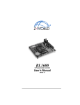
The user interface
The configuration of the user interface is made through the setup panel and the
context menu of the components.
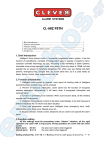
The user interface consists of three main elements
• The tabbed panel
• The tab pane
• The side panel
tab pane
side panel
tabbed panel
With the tabs you can select the tabbed panel, which brought the stack upwards
and is therefore visible.
In the setup it is possible to configure a "single panel".
The single panel there is only one panel and the tab area is hidden.
© 2011 pbe - Peter Beck
page: 13 of 114
www.p-b-e.de
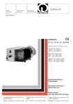
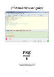
The tab pane can be arranged on all four sides of the tabbed panel:
• top
• bottom
• left
• right
top
bottom
left
The height of the tabs can be also configuring in the setup.
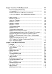
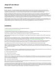
The side panel can be arranged either as follows:
• left
• right
• hidden
left
right
hidden
Single panel without tab pane and side panel
© 2011 pbe - Peter Beck
page: 14 of 114
www.p-b-e.de
The tab area
The tab pane is used to switch the tabbed panels and includes the main context
menu with the setup access.
main context menu
Each tabbed panel is represented with its name as a tab in the tab pane.
Tabs can to be relocaded with the mouse by clicking and holding down the left
mouse button.
© 2011 pbe - Peter Beck
page: 15 of 114
www.p-b-e.de
The context menu of the tab pane
The context menu can be reached with a right mouse click on the tab pane.
user mode
configuration mode
standard
with hidden panels
new tab
The menu item "new tab" creates a new empty tabbed panel.
side panel
The side panel reappears with the menu item "side panel".
start macro
The menu item "start macro" opens the macro windows, where you can define a
macro which executed after start up once. With this macro system status can be
request after start up.
Definition of the macro see section macro button.
© 2011 pbe - Peter Beck
page: 16 of 114
www.p-b-e.de
size and position
This menu item opens the auxiliary window "size and position". With this auxiliary
window the currently selected component can be positioned and resized.
undo
With the menu item "undo" accidentally moved component by mouse cannot be put
again back to its previous position.
Also, text entries in the properties can be reversed
An accidentally deleted component can also be restored.
It should be noted, that there is a new component after the restoration.
Any changes before the deletion can not be restored!
Deleting a root panels, such as a tabbed panel, a single panel or the side panel,
cannot be undone.
redo
With the menu item "redo", an action taken by "undo" is withdrawn.
save
With the menu item "save" the current configuration of homeVisu is stored in the
file homeVisu.ini.
all visible
With the menu item "all visible" all hidden panels appear at once.
© 2011 pbe - Peter Beck
page: 17 of 114
www.p-b-e.de
HV1, HV2, HVxx
This menu item makes the hidden panel with the displayed number visible.
Example:
From the demo menu item HV2 makes the hidden panel HV2 visible, which is
named "floor plan".
setup
With the menu item "setup" you get into the setup of homeVisu.
Program settings can be made in the setup.
The settings of all loaded devices are also in the setup available.
info
With the menu item "info", the info window is opened.
The info window displays the version number and the licensee of the homeVisu
installation.
© 2011 pbe - Peter Beck
page: 18 of 114
www.p-b-e.de
The setup
The menu item "setup" in the tab pane context menu takes you to the setup.
If the setup is protected by password, the password dialog appears:
Note:
At first program startup the password query is enabled.
There is no password assigned. Without entering a password confirm the dialog
with OK.
setup tree
By clicking on the tree item,
the corresponding configuration
panel opens
© 2011 pbe - Peter Beck
page: 19 of 114
www.p-b-e.de
Setup password
Setup access can be secured with a password.
In this configuration panel the setup password can be enabled and assign or
changed the password.
Changing the password
Once the password is changed, and the password confirmation is not identical with
the password the field becomes red or green when correctly confirmed.
© 2011 pbe - Peter Beck
page: 20 of 114
www.p-b-e.de
Operating mode
homeVisu
can be configured according to the operating mode.
The operating mode is set in the configuration panel.
users
Any configuration options are disabled.
Components can not positioned or resized.
All context menus are turned on.
The tab context menu is reduced on the items setup and info.
The reordering of the tabs is the user allowed, but will not permanently store.
configuration
All configuration options are enabled.
© 2011 pbe - Peter Beck
page: 21 of 114
www.p-b-e.de
Frame setup
homeVisu starts by default as a window.
This configuration panel defines the appearances of the window at startup.
Frame size
Defines the frame size at startup
frame resizeabe
Activate or deactivate the possibility to resize the homeVisu window.
frame without title bar
This check button disabled the title bar, the frame is undecorated.
frame always on top
is always on top of the desktop.
homeVisu
frame location
Defines the frame location at startup. Either centered on desktop or at given
position.
© 2011 pbe - Peter Beck
page: 22 of 114
www.p-b-e.de
Panel setup
The basic appearance of the user interface can be adjusted to appropriate needs in
this configuration panel.
panel type
• tabbed
several panels that can be selected by the tab pane.
• single
only one Panel. The tab pane is hidden.
tab: position of the tab pane in relation to the tabbed panel.
• top
• bottom
• left
• right
Tab height: The height of the tabs can be set here.
Side panel position: Position of the side panel in relation to the tabbed panel
© 2011 pbe - Peter Beck
page: 23 of 114
www.p-b-e.de
Server setup
When server is activated, clients can remote control homeVisu over the defined
port.
By sending commands - like the macro commands - a command will execute.
The server transmits all status messages to the clients. The client must only receive
the status messages and visualize them.
status messages from system device
Activate the transmition of status messages from the system device.
The system device transmits every second the date of the server.
server ip-port
Here you can define the port number of the server.
© 2011 pbe - Peter Beck
page: 24 of 114
www.p-b-e.de
Multi user
In the professional version, a group can be defined, were the group members can
communicate and exchange information with each other.
The group is defined in this configuration panel.
© 2011 pbe - Peter Beck
page: 25 of 114
www.p-b-e.de
INI files
In the professional version, additional INI files can be defined, they are loaded at
startup.
Overwrite values prior INI files is possible. The last loaded INI values are valid.
By specifying a path, the INI files can be loaded from a server to use common
settings in the multi user mode.
This configuration panel defines the list and the order of the INI files.
© 2011 pbe - Peter Beck
page: 26 of 114
www.p-b-e.de
Active timer
All active timers are listed in this overview.
This is a centralized view, to identify the timer and its associated buttons.
Changes can not be performed here. To change timers, the timer must be changed
in the timer window of the associated button.
© 2011 pbe - Peter Beck
page: 27 of 114
www.p-b-e.de
Full screen mode
In the professional version in this configuration panel the full screen mode can be
activated and the cursor can be hidden.
Full screen
homeVisu will capture the entire screen without window frames.
In full-screen mode it is not possible to terminate the application.
No Cursor
For applications with touch screen, the cursor can be hidden here.
© 2011 pbe - Peter Beck
page: 28 of 114
www.p-b-e.de
Look and Feel
The basic look and feel of homeVisu can be changed in this configuration panel.
All look and feel comes with Java can be selected directly using the buttons.
Please note that under Windows, the GTK LAF and under Linux the Windows LAF is
not available.
Entering the Java class name of a loaded Look And Feel every available or created
Look And Feel can also be integrated.
Your own Look And Feel classes can be copied as a JAR files into the homeVisu
subdirectory /libs.
The classes in the libs directory are loaded at startup by homeVisu.
A program restart is required for an entire change of the look and feel.
© 2011 pbe - Peter Beck
page: 29 of 114
www.p-b-e.de
Language
The language of the menus, setup and configuration windows of homeVisu can be
changed.
All language elements are stored independent from the source code in language
files and can be freely translated into any language.
In this configuration panel the language for the next startup is selected.
Default language files are available for German (Deutsch.lng) and English
(English.lng).
The files are located in the installation directory.
Each device and each additional component has its own language file.
New language files are generated by a copying and renaming an existing language
file.
e.g. English.lng
Français.LNG
PLCBUS_English.LNG
PLCBUS_Français.LNG
After copying the text in the file right of the equal sign must be translated.
© 2011 pbe - Peter Beck
page: 30 of 114
www.p-b-e.de
The base panels
There
•
•
•
are three versions of base panels
tabbed panel
single panel
side panel
All panels can include as many components.
The components can be freely positioned on the panel.
There are four differences in the panels.
1. The single panel can not be hidden.
2. The context menu of the single panel includes additional menu items from
the context menu of the missing tab pane (undo, redo, save, setup, info).
3. The context menu of the single panel includes additional menu item “new
panel”, to generate new single panel.
4. The width of the side panels can be set.
Either in the setup, in the properties window or by mouse dragging on the
side of the tabbed panel if the mouse pointer will change accordingly.
All panels are configured by its context menu.
© 2011 pbe - Peter Beck
page: 31 of 114
www.p-b-e.de
The context menu of the panels
tabbed panel
single panel
side panel
name
With the input field in the context menu enter the name of the panel.
© 2011 pbe - Peter Beck
page: 32 of 114
www.p-b-e.de
properties
The "properties" menu item opens the properties window of the panel, where all
properties can be set.
macro
The menu item "macro" opens the macro windows, where you can define a macro
which will execute always you jump to this panel. With this macro system status
can be request after each panel switch.
Definition of the macro see section macro button.
export
With the menu item "export" the panel can be exported in a file.
After clicking on the menu, a dialog opens where the file can be selected or created.
When exporting a panel all included components are exported in same file.
Any associated files such as graphics are not written in the export file!
import
Exported components can be imported again with the "import" menu item.
After clicking on the menu, a dialog opens where the file can be selected.
paste
Components previously selected by menu item "copy" can be insert with the menu
item "paste". It inserts a copy of the component.
© 2011 pbe - Peter Beck
page: 33 of 114
www.p-b-e.de
invisible
With the menu item "invisible" the panel is hidden. It remains in the background
and can reappear at any time by the context menu of the tab pane.
delete
With the menu item "delete" the panel is compared to invisible permanently
deleted.
size and position
This menu item opens the auxiliary window “size and position". With this auxiliary
window the currently selected component can be positioned and resized.
group panel
The menu item "group panel" inserts a new group panel at the cursor position.
macro button
The menu item "macro button" inserts a new macro button at the cursor position.
status field
The menu item "status field" inserts a new status field at the cursor position.
basic slider
The menu item "basic slider" inserts a new basic slider at the cursor position.
© 2011 pbe - Peter Beck
page: 34 of 114
www.p-b-e.de
other components
If in the subfolder "\ components" other components such as in the example the
components "OnlyAnImage" and "PLC-BUS module” are installed, they will appear
here in the context menu to choose.
With the selection in context menu the corresponding component is inserted at the
cursor position.
all visible
With the menu item "all visible" all in the panels hidden components are appear at
once.
HVxx
With the menu item HVxx the hidden component HVxx reappears.
new panel
Only single panel!
This menu item generates a new single panel. There are no limits of additional
single panels. To make a single panel visible, use the JUMP command of the System
device.
The properties of the panels
name
With the input field enter the name of the panel.
© 2011 pbe - Peter Beck
page: 35 of 114
www.p-b-e.de
The name appears in the frame.
For the tabbed panel the name also serves to label the tabs in the tab pane.
font size
It sets the font size of the name in the frame.
font style
It sets the font style of name in the frame.
• plain
• bold
• italics
• bold + italics
background
The using of a background is enabled.
A color and a graphic can be defined for background.
The graphic is above the colored background so the colored background is visible
around the graphic.
color
The selected background color is displayed in the color field.
opens a color selection dialog.
A double click on the color field or the button
Key del will delete the chosen color.
image file
The file name of an image file can be entered in the input field.
Paths are possible here.
An input must confirmed with >enter< to load the file.
A double click on the input field or the button
opens a file selection dialog.
style
If a background image is set, here can be defined how the graphic is displayed.
• scaled
graphic is adjusted to the background.
• tiles
a small picture is tiled.
• actual
graphic is presented unchanged.
horizontal
The horizontal position of a graphic is defined here.
This function has only effect in a graphic, which is less than the background and is
shown actually.
© 2011 pbe - Peter Beck
page: 36 of 114
www.p-b-e.de
vertical
The vertical position of a graphic is defined here.
This function has only effect in a graphic, which is less than the background and is
shown actually.
frame
The visibility of the frame is on or off.
transparent
The panel is transparent.
© 2011 pbe - Peter Beck
page: 37 of 114
www.p-b-e.de
The components
There
•
•
•
•
are 4 standard components
group panel
macro button
status field
basic slider
These components are always included in homeVisu.
Additional components can be installed at any time as a plug-in. To do this, the
appropriate JAR file must be copied in the subdirectory "\components".
Any component that has been copied into the subdirectory is after startup available
and can be inserted.
As an example, the component "PLC BUS module" is described in this manual.
Size and position
All components can be freely positioned and resized.
Here too there are a variety of ways.
These features are only available in the configuration mode.
with the mouse
Each component can be moved and resized with the mouse.
If you move the mouse along to the edge of the component, the mouse pointer is
changing. According to the mouse pointer the component can be resized in the
appropriate direction.
In the middle of the upper edge, the cursor becomes a cross; which indicates that
the component can now be moved with the pressed left mouse button.
Another method is with the CTRL and SHIFT key together with the right mouse
button.
A hold down the SHIFT key together with the right mouse button on any part of the
component increase or reduces the component synchronously with moving the
mouse.
By holding down the CTRL key, the component can be moved with the right mouse
button.
© 2011 pbe - Peter Beck
page: 38 of 114
www.p-b-e.de
auxiliary window “size and position"
With auxiliary window size and position each component can be positioned and
resized exactly to pixels.
To edit a component with the auxiliary window, you must select the component
previously with the mouse. Either with a left or right mouse click on it.
The Group panel
Empty group panel with frame
The group panel can include as many components like the base panels. In this case
a group can include to another group panel. Thus, group panels can be nested.
All inserted components can be positioned freely on the group panel.
Nested group panel
The group panel is configured by its context menu.
© 2011 pbe - Peter Beck
page: 39 of 114
www.p-b-e.de
The context menu of the group panel
Basically, the group panel has the same context menu as the base panels.
There are only 2 additional menu items.
• to foreground
• copy
All other menu items are identical to the menu items of the base panels.
to foreground
All components within a panel have a stack position. That is, the components cover
each other.
Only the top component on the stack is fully visible.
With this function the component is moving on the top of the stack within its panel,
so in the foreground.
copy
With the menu item "copy" the group panel including its components is marked for
copying.
The properties of the group panel
The properties of the group panel correspond to the properties of base panels plus
the property "show image", “transparency” and the position and size properties.
© 2011 pbe - Peter Beck
page: 40 of 114
www.p-b-e.de
show image
Use this property; partially transparent graphics can be used as backgrounds so
that in the transparent areas of the graphic the background of the base panel or of
the parent panel is visible.
position
With the properties X pos and Y pos, the position of the group panel can define
exactly on the pixel.
size
With the properties width and height, the size of the group panel can define exactly
on the pixel.
The macro button
macro button
© 2011 pbe - Peter Beck
page: 41 of 114
www.p-b-e.de
The macro button executes the commands provided by the devices.
The macro button can process a command list and address all devices within a
sequence (macro).
There are many options for the macro button. From the appearance, the command
list, the visibility and the enable as a function of events and timers.
Each macro button can have as many timers.
The timer controls either the command execution, the visibility or the enable of the
button.
The macro button is configured by its context menu.
The context menu of the macro button
© 2011 pbe - Peter Beck
page: 42 of 114
www.p-b-e.de
button text
With the input field in the context menu enter the text of the button.
properties
The "properties" menu item opens the properties window of the macro button,
where all properties can be set.
© 2011 pbe - Peter Beck
page: 43 of 114
www.p-b-e.de
macro
The "macro" menu item opens the macro window of the macro button.
The macro window defines the command list that is executed when button is
pressed.
set status
The "set status" menu item opens the event window of the macro button.
The event window defines to which status messages from the devices the button
responds. Thus, the visibility or the enable can be changed depending on device
status messages.
© 2011 pbe - Peter Beck
page: 44 of 114
www.p-b-e.de
timer
The "timer" menu item opens the timer window of the macro button.
The timer window defines the timers for the button. Thus, the command execution,
the visibility or the enable depending on a timer can be activated.
There are three types of timers available.
• date
• periodically
• weekly
export
With the menu item "export" the macro button can be exported in a file.
After clicking on the menu, a dialog opens where the file can be selected or created.
Any associated files such as graphics are not written in the export file!
to foreground
All components within a panel have a stack position. That is, the components cover
each other.
Only the top component on the stack is fully visible.
With this function the macro button is moving on the top of the stack within its
Panel, so in the foreground.
copy
With the menu item "copy" the macro button is marked for copying.
© 2011 pbe - Peter Beck
page: 45 of 114
www.p-b-e.de
enable/disable
With the menu item "enable" or "disable", the macro button’s command execution
is blocked or released. Disable also prevents the command execution by a timer.
invisible
With the menu item "invisible" the macro button is hidden. It remains in the
background and can reappear at any time by the context menu of its panel.
delete
With the menu item "delete" the macro button is compared to invisible permanently
deleted.
© 2011 pbe - Peter Beck
page: 46 of 114
www.p-b-e.de
The properties of the macro button
The "properties" menu item opens the properties window of the macro button,
where all appearance properties can be set.
name
With the input field enter the text of the button.
font size
It sets the font size of the button text.
© 2011 pbe - Peter Beck
page: 47 of 114
www.p-b-e.de
font style
It sets the font style of the button text.
• plain
• bold
• italics
• bold + italics
font color
It sets the font color of the button text for each state.
• button
– text color in the normal state
• over
– text color if mouse over
• pressed
– text color if button pressed
• disabled
– text color if button disabled
The selected font color is displayed in the color field.
opens a color selection dialog.
A double click on the color field or the button
Key del will delete the chosen color.
images
The representation of background images is enabled.
Images can be defined for:
• button
• over
• pressed
• diabled
button
The file name of an image can be entered in the input field that appears in the
normal state.
Paths are possible here.
An input must confirmed with >enter< to load the file.
A double click on the input field or the button
opens a file selection dialog.
© 2011 pbe - Peter Beck
page: 48 of 114
www.p-b-e.de
over
The file name of an image can be entered in the input field that appears if the
mouse is over.
Paths are possible here.
An input must confirmed with >enter< to load the file.
A double click on the input field or the button
opens a file selection dialog.
pressed
The file name of an image can be entered in the input field that appears if the
button is pressed.
Paths are possible here.
An input must confirmed with >enter< to load the file.
A double click on the input field or the button
opens a file selection dialog.
disabled
The file name of an image can be entered in the input field that appears if the
button is disabled.
Paths are possible here.
An input must confirmed with >enter< to load the file.
A double click on the input field or the button
opens a file selection dialog.
© 2011 pbe - Peter Beck
page: 49 of 114
www.p-b-e.de
style
If an
•
•
•
image is set, here can be defined how the graphic is displayed.
scaled
graphic is adjusted to the background.
tiles
a small picture is tiled.
actual
graphic is presented unchanged.
image text
If a background image is set, here can be turned on the function text on graphics.
Alternatively, the text can be drawn with the graphics.
frame
The visibility of the frame is on or off.
transparent
The macro button is transparent.
show image
Use this property; partially transparent graphics can be used as backgrounds so
that in the transparent areas of the graphic the background of the base panel or of
the parent panel is visible.
position
With the properties X pos and Y pos, the position of the macro button can define
exactly on the pixel.
size
With the properties width and height, the size of the macro button can define
exactly on the pixel.
© 2011 pbe - Peter Beck
page: 50 of 114
www.p-b-e.de
The macro window
The macro window defines the command list that is executed if button pressed.
macro list
create a macro
With the device selection choose the device, whose command has to execute.
Define the command in the command definition and add the command into the
command list (macro).
device selection
© 2011 pbe - Peter Beck
page: 51 of 114
www.p-b-e.de
command definition
define command
add command
Each command in the command list is executed in the order.
© 2011 pbe - Peter Beck
page: 52 of 114
www.p-b-e.de
examples of macros
Relay 1 of device RELAYS8 and board address 1 is switched on for 1 second.
switch ON relay 1
wait 1000 ms
switch OFF relay 1
switch ON PLC-BUS module A1; user code FF; 1-phase
BRIGHT PLC-BUS module A1; user code FF; 1-phase; fade rate 3
wait 1000 ms
STOP fade PLC-BUS module A1; user code FF; 1-phase
© 2011 pbe - Peter Beck
page: 53 of 114
www.p-b-e.de
load selection
The command selected in the command list is loaded in the command definition to
make a change to the command.
A command can be loaded as well with a double click or press the Enter button.
add
The command in the command definition is added to the command list.
If a command is selected in the command list, the new command is inserted behind
the selected command.
If no selection is made, the command is inserted at the end of the command list.
replace
The command in the command definition replaces the selected command in the
command list.
If no selection is made, the command is inserted at the end of the command list.
del
The selected command in the command list is deleted.
up
The selected command in the command list moves up one position. So the
command is executed before its current predecessor.
down
The selected command in the command list moves down one position.
close
Close the macro window.
© 2011 pbe - Peter Beck
page: 54 of 114
www.p-b-e.de
The event window
The event window defines the button responds to which status messages from the
devices. Thus, the visibility or the enable can be changed depending on device
status messages.
device selection
event list
status definition
create an event
With the device selection choose the device, whose status should be processed.
Define the status in the status definition, choose the event function and add the
event into the event list.
device selection
© 2011 pbe - Peter Beck
page: 55 of 114
www.p-b-e.de
status definition
event function
define event
add event
Each event in the event list is checked for status messages that are sent from the
device and may be executed.
© 2011 pbe - Peter Beck
page: 56 of 114
www.p-b-e.de
examples of events
The button is released (ENABLE) as soon as the device PLCBUS sends the status
message CONNECT TRUE.
ENABLE: PLCBUS: TRUE: CONNECT
If the device PLCBUS sends the status message CONNECT FALSE the button is
locked (DISABLE)
DISABLE: PLCBUS: FALSE: CONNECT
event status
The event status defines whether the event responds to a true status or to a false
status.
event function
The event function defines which event will executed.
action
visible
invisible
enable
disable
© 2011 pbe - Peter Beck
command execution (macro)
show button
hide button
release button
lock button
page: 57 of 114
www.p-b-e.de
load selection
The event selected in the event list is loaded in the status definition to make a
change to the event.
An event can be loaded as well with a double click or press the Enter button.
add
The event in the event definition is added to the event list.
If an event is selected in the event list, the new event is inserted behind the
selected command.
If no selection is made, the event is inserted at the end of the event list.
replace
The event in the event definition replaces the selected event in the event list.
If no selection is made, the event is inserted at the end of the event list.
del
The selected event in the event list is deleted.
close
Close the event window.
© 2011 pbe - Peter Beck
page: 58 of 114
www.p-b-e.de
The timer window
The timer window defines the timers for the button. Thus, the command execution,
the visibility or the enable depending on a timer can be activated.
There are three types of timers available.
• date
• periodically
• weekly
the date timer
The date timer defines a timer running on a certain day at a given time.
timer function
timer list
© 2011 pbe - Peter Beck
page: 59 of 114
www.p-b-e.de
the periodically timer
The periodic timer defines a timer that repeats from a certain date and time at a
given interval (period).
timer date
period
the weekly timer
The weekly timer defines a timer that repeats from a certain date on the defined
weekdays at the given time.
time
week day
© 2011 pbe - Peter Beck
page: 60 of 114
www.p-b-e.de
timer function
There are 5 functions for the timer available, the timer will be executed.
action
visible
invisible
enable
disable
command execution (macro)
show button
hide button
release button
lock button
now
With the button "now" in the timer window, the date and time definition is set to
the current time
choose date
The button "select date" in the timer window, opens a dialog for date selection.
With this dialog the date can be selected in a calendar view quickly and easily.
© 2011 pbe - Peter Beck
page: 61 of 114
www.p-b-e.de
add timer
The timer is added to the timer list and will start.
If a timer in the timer list is selected, a dialog is shown, whether the timer should
be replaced or added.
del timer
The selected timer in the timer list is deleted and stopped.
close
Close the timer window.
© 2011 pbe - Peter Beck
page: 62 of 114
www.p-b-e.de
The status field
The status field visualized status messages reported by the devices.
Each status field can have two appearances
•
•
status is false (FALSE)
status is true (TRUE)
FALSE
TRUE
text version
image version
The status field is configured by its context menu.
The context menu of the status field
status text
With the input field in the context menu enter the status text for status <FALSE>
of the field. The field text for status <FALSE> is the default appearance after
initialization.
© 2011 pbe - Peter Beck
page: 63 of 114
www.p-b-e.de
properties
The "properties" menu item opens the properties window of the status field, where
all properties for the appearances can be set.
set status
The "set status" menu item opens the status window of the status field.
The status window defines which status messages of which device the status field
visualizes.
© 2011 pbe - Peter Beck
page: 64 of 114
www.p-b-e.de
export
With the menu item "export" the status field can be exported in a file.
After clicking on the menu, a dialog opens where the file can be selected or created.
Any associated files such as graphics are not written in the export file!
to foreground
All components within a panel have a stack position. That is, the components cover
each other.
Only the top component on the stack is fully visible.
With this function the status field is moving on the top of the stack within its panel,
so in the foreground.
copy
With the menu item "copy" the status field is marked for copying.
invisible
With the menu item "invisible" the status field is hidden. It remains in the
background and can reappear at any time by the context menu of its panel.
delete
With the menu item "delete" the status field is compared to invisible permanently
deleted.
© 2011 pbe - Peter Beck
page: 65 of 114
www.p-b-e.de
The properties of the status field
The "properties" menu item opens the properties window of the status field, where
all properties for the appearances can be set.
Definition of the
appearance.
Status is TRUE
test status
The appearance of the status field can be switched with the button. So the
representation of states can be tested when creating applications.
activate
Here will be the second state >TRUE< of the status field enabled.
© 2011 pbe - Peter Beck
page: 66 of 114
www.p-b-e.de
value
The selection defines what the status field should represent.
According as to the device status, which was defined by the function "set status",
available status information offered here that can also be represented.
TEXT it means the text entered in the input field "text" is represented.
The status information’s, which are transmitted from the device status, can be also
integrated in the texts.
text
With the input field enter the status text which should be represented according to
the status in the status field.
For the integration of status information placeholder must be integrated into the
text.
This placeholder is the index number in the status information selection embedded
in curly braces.
e.g.
a1: brightness ={1}% fade rate = {2}
possible presentation:
a1: brightness = 75% fade rate = 3
font size
It sets the font size of the button text.
font style
It sets the font style of the button text.
• plain
• bold
• italics
• bold + italics
© 2011 pbe - Peter Beck
page: 67 of 114
www.p-b-e.de
text color
The set text color is shown in the color field.
A double click on the color field or the button
Key del will delete the chosen color.
opens a color selection dialog.
background color
The set background color is shown in the color field.
opens a color selection dialog.
A double click on the color field or the button
Key del will delete the chosen color.
Note:
If the background color has to match to the color of the Panel choose the attribute
"transparent". So it is guaranteed that with a look and feel switching, the color is
still the same.
images
The representation of background images is enabled.
image file
The file name of an image can be entered in the input field.
Paths are possible here.
An input must confirmed with >enter< to load the file.
A double click on the input field or the button
opens a file selection dialog.
style
If a background image is set, here can be defined how the graphic is displayed.
• scaled
graphic is adjusted to the background.
• tiles
a small picture is tiled.
• actual
graphic is presented unchanged.
image text
If a background image is set, here can be turned on the function text on graphics.
Alternatively, the text can be drawn with the graphics.
frame
The visibility of the frame is on or off.
© 2011 pbe - Peter Beck
page: 68 of 114
www.p-b-e.de
transparent
The status field is transparent.
show image
Use this property; partially transparent graphics can be used as backgrounds so
that in the transparent areas of the graphic the background of the base panel or of
the parent panel is visible.
position
With the properties X pos and Y pos, the position of the status field can define
exactly on the pixel.
size
With the properties width and height, the size of the status field can define exactly
on the pixel.
The set status windows
The status window defines which status messages of which device the status field
visualizes.
device selection
device status definition
© 2011 pbe - Peter Beck
page: 69 of 114
www.p-b-e.de
setting the status listener
With the device selection choose the device, whose status should be processed.
Define the status message in the status definition and set the status with the
button “set status”.
If required the status can be negated.
device selection
define status message
set status
status negation
If required the status can be negated.
© 2011 pbe - Peter Beck
page: 70 of 114
www.p-b-e.de
set status
With the button “set status” the selected device and the defined status message are
taken over and presented in the same-named fields.
A status field shows the status messages from the device that is registered in the
fields "choosed device" and "chossed source".
negation
Negation reverses the status.
The status field now represents a true state as false and one false as true.
close
Close the set status window.
© 2011 pbe - Peter Beck
page: 71 of 114
www.p-b-e.de
The multi status field
The multi status field extended the status field for the property to visualize the
state of more than one status messages.
The multi status field you can use especially by group addresses.
When a module which you want to visualize is member in additional group
addresses you can visualize also commands to this group addresses.
The multi status field just visualize the state of a status message. It could not
visualize values; they are sended with the status message.
Only the window for setup the status listeners is different to the status field.
Here you can define a list.
© 2011 pbe - Peter Beck
page: 72 of 114
www.p-b-e.de
The basic slider
The basic slider is a graphical slider which visualizes state values as well, can send
commands with values to the devices.
The basic slider can be displayed horizontally or vertically.
The direction can be adjusted either from right to left or left to right and from top
to bottom or bottom to top.
The basic slider is configured by its context menu.
The context menu of the basic slider
name
With the input field in the context menu enter the name of the basic slider.
© 2011 pbe - Peter Beck
page: 73 of 114
www.p-b-e.de
properties
The "properties" menu item opens the properties window of the basic slider, where
all properties for the appearances can be set.
set value
The "set value" menu item opens the set value window of the basic slider.
The value window defines which status messages of which device the basic slider
visualizes, as well as which command with which command parameter the basic
slider send to the device, when the basic slider is positioned with the mouse.
© 2011 pbe - Peter Beck
page: 74 of 114
www.p-b-e.de
export
With the menu item "export" the basic slider can be exported in a file.
After clicking on the menu, a dialog opens where the file can be selected or created.
Any associated files such as graphics are not written in the export file!
to foreground
All components within a panel have a stack position. That is, the components cover
each other.
Only the top component on the stack is fully visible.
With this function the basic slider is moving on the top of the stack within its panel,
so in the foreground.
copy
With the menu item "copy" the basic slider is marked for copying.
invisible
With the menu item "invisible" the basic slider is hidden. It remains in the
background and can reappear at any time by the context menu of its panel.
delete
With the menu item "delete" the basic slider is compared to invisible permanently
deleted.
© 2011 pbe - Peter Beck
page: 75 of 114
www.p-b-e.de
The properties of the basic sliders
The "properties" menu item opens the properties window of the basic slider, where
all appearance properties can be set.
name
With the input field enter the name of the basic slider.
The name appears in the frame.
The value of the slider can be also integrated in the name.
For the integration of the value a placeholder {0} must be integrated into the
name.
e.g.
possible presentation:
a1: brightness {0}%
a1: brightness 75%
© 2011 pbe - Peter Beck
page: 76 of 114
www.p-b-e.de
font size
It sets the font size of the name in the frame.
font style
It sets the font style of name in the frame.
• plain
• bold
• italics
• bold + italics
maximum
Defines the maximum scale value of the slider.
minumum
Defines the minimum scale value of the slider.
inverse
This switch reverses the direction of the slider.
© 2011 pbe - Peter Beck
page: 77 of 114
www.p-b-e.de
track
With this switch, the tracks are turned on or off.
labels
With this switch, the scales labels are turned on or off.
Labels are always at the major ticks.
ticks
With this switch, the scales ticks are turned on or off.
major ticks
Increment of the major ticks.
A value of 0 turns off the major ticks.
minor ticks
Increment of the minor ticks.
A value of 0 turns off the minor ticks.
© 2011 pbe - Peter Beck
page: 78 of 114
www.p-b-e.de
snap to ticks
With this switch, the slider jumps to the next tick when you move the slider by
mouse. The lowest step corresponds to the increment of the minor ticks.
animation
With the animation, the speed of the slider animation is set. The slider button
moves animated when getting a value changes. The smaller the value more quickly
moves the slider to its new location. A value of 0 disables the animation. The slider
immediately jumps to its new value.
images
The representation of background and thumb images is enabled.
Images can be defined for:
• background
• thumb
• thumb rollover
background and thumb image
background and rollover thumb
background
The file name of an image can be entered in the input field that appears as
background.
Paths are possible here.
An input must confirmed with >enter< to load the file.
A double click on the input field or the button
opens a file selection dialog.
© 2011 pbe - Peter Beck
page: 79 of 114
www.p-b-e.de
thumb
The file name of an image can be entered in the input field that appears as thumb.
Paths are possible here.
An input must confirmed with >enter< to load the file.
A double click on the input field or the button
opens a file selection dialog.
thumb rollover
The file name of an image can be entered in the input field that appears as thumb if
rollovers thumb.
Paths are possible here.
An input must confirmed with >enter< to load the file.
A double click on the input field or the button
opens a file selection dialog.
style
If an
•
•
•
background image is set, here can be defined how the graphic is displayed.
scaled
graphic is adjusted to the background.
tiles
a small picture is tiled.
actual
graphic is presented unchanged.
frame
The visibility of the frame is on or off.
transparent
The basic slider is transparent.
show image
Use this property; partially transparent graphics can be used as backgrounds so
that in the transparent areas of the graphic the background of the base panel or of
the parent panel is visible.
© 2011 pbe - Peter Beck
page: 80 of 114
www.p-b-e.de
position
With the properties X pos and Y pos, the position of the basic slider can define
exactly on the pixel.
size
With the properties width and height, the size of the basic slider can define exactly
on the pixel.
The value window
The "set value" menu item opens the set value window of the basic slider.
The value window defines which status messages of which device the basic slider
visualizes, as well as which command with which command parameter the basic
slider send to the device, when the basic slider is positioned with the mouse.
device selection
function selection
source
source or command definition
command
© 2011 pbe - Peter Beck
page: 81 of 114
www.p-b-e.de
setting the value listener
With the device selection choose the device, whose status message (source) should
be processed. Choose function source, define the status message in the source
definition and set the source with the button “set source”.
At last choose source value that should be visualized by the slider.
device selection
choose function source
define status (source)
set source
choose source value that should be visualized through the slider.
© 2011 pbe - Peter Beck
page: 82 of 114
www.p-b-e.de
set command
With the device selection choose the device, whose command is to execute.
Choose function command, define the command in the command definition and set
the command with the button “set command”.
At last choose command parameter that is transmitted with the command.
device selection
choose function command
define command
set command
The selected command parameter
is highlighted in green.
choose command parameter that is transmitted with the command
© 2011 pbe - Peter Beck
page: 83 of 114
www.p-b-e.de
set source
With the button “set source” the selected device and the defined status message
(source) are taken over and presented in the same-named fields.
choose source value
In this selection, all with the status transmitted source values are available.
For example with the status message DIMSTATE of the PLCBUS device the source
values brightness and fade rate are transmitted.
set command
With the button “set command” the selected device and the defined command are
taken over and presented in the same-named fields.
© 2011 pbe - Peter Beck
page: 84 of 114
www.p-b-e.de
choose command parameter
In this selection all command parameters are available that can be parameterized
with the value of the slider.
The selected command parameter is highlighted in green.
close
Close the value window.
© 2011 pbe - Peter Beck
page: 85 of 114
www.p-b-e.de
The PLCBUS module
The PLCBUS module is a component plug-in that can be installed or removed as
needed.
To install a component plug-in copy the JAR file in the subdirectory "\components".
Alternatively the plug-in can be removed by deleting the JAR file.
The PLCBUS module is a special component for the PLCBUS device and only works
with installed PLCBUS device.
Depending on configuration, the PLCBUS module can become 5 basic appearances.
The PLCBUS module is configured by its context menu.
The context menu of the PLCBUS module
© 2011 pbe - Peter Beck
page: 86 of 114
www.p-b-e.de
name
With the input field in the context menu enter the name of the PLCBUS module.
properties
The "properties" menu item opens the properties window of the PLCBUS module,
where all properties can be set.
© 2011 pbe - Peter Beck
page: 87 of 114
www.p-b-e.de
scene addressens
The "scene addresses" menu item opens the window for scene addresses definition.
Each real PLC-BUS module could have up to 16 additional scene addresses it listens
to.
So that commands they are sended to such scene address programmed inside the
real module also could visualize by the graphic module, you can define these scene
addresses for graphic module here.
setup dimmer
The "setup dimmer" menu item opens the dimmer setup window of the PLCBUS
module. With the dimmer settings, the dimmer values for the brightness and the
fade rate of the corresponding real PLC-BUS module can be queried or set.
The menu item is only enabled, if the PLC-BUS address is defined in the properties
window.
© 2011 pbe - Peter Beck
page: 88 of 114
www.p-b-e.de
dimmer step
With the menu item "dimmer step" step sizes of the dimmer can be defined, that
are executed by the buttons brighten and dimming.
export
With the menu item "export" PLCBUS module can be exported in a file.
After clicking on the menu, a dialog opens where the file can be selected or created.
Any associated files such as graphics are not written in the export file!
to foreground
All components within a panel have a stack position. That is, the components cover
each other.
Only the top component on the stack is fully visible.
With this function the PLCBUS module is moving on the top of the stack within its
panel, so in the foreground.
copy
With the menu item "copy" the PLCBUS module is marked for copying.
invisible
With the menu item "invisible" the PLCBUS module is hidden. It remains in the
background and can reappear at any time by the context menu of its panel.
delete
With the menu item "delete" the PLCBUS module is compared to invisible
permanently deleted.
© 2011 pbe - Peter Beck
page: 89 of 114
www.p-b-e.de
dimmer
The appearance is converted into a dimmer.
Dimmers are coupled with the PLC BUS command ALL LAMPS ON or OFF.
status field
A double click in the status field of a
dimmer triggered a status query of the
dimmer.
button labels,
can be changed with the right mouse.
lamp
The appearance is converted into a lamp.
Lamps are coupled with the PLC BUS command ALL LAMPS ON or OFF.
button labels,
can be changed with the right mouse.
relay
The appearance is converted into a relay.
Relays respond only to the PLC BUS command ALL UNIT OFF!
button labels,
can be changed with the right mouse.
© 2011 pbe - Peter Beck
page: 90 of 114
www.p-b-e.de
shutter
The appearance is converted into a shutter.
scene
The appearance is converted into a scene.
button labels,
can be changed with the right mouse.
© 2011 pbe - Peter Beck
page: 91 of 114
www.p-b-e.de
The properties of the PLCBUS module
The "properties" menu item opens the properties window of the PLCBUS module,
where all appearance properties PLCBUS address settings can be set.
name
With the input field enter the name of the PLCBUS module.
The name appears in the frame.
font size
It sets the font size of the name in the frame.
font style
It sets the font style of name in the frame.
• plain
• bold
• italics
• bold + italics
© 2011 pbe - Peter Beck
page: 92 of 114
www.p-b-e.de
ON color
The ON color defines the color of the status field and the frame if the status is ON
The selected color is displayed in the color field.
A double click on the color field or the button
opens a color selection dialog.
The status color of a dimmer can not be changed!
frame
The visibility of the frame is on or off.
transparent
The PLCBUS module is transparent.
user code
The user code of the PLC-BUS address to which PLCBUS module is to be connected
to, is set here.
By default always the preset from the setup appears at new module components.
But can be customized for each module component.
room adr
The room address of the PLC BUS address to which the PLCBUS module is to be
connected to, is set here.
unit adr
The unit address of the PLC BUS address to which the PLCBUS module is to be
connected to, is set here.
phase
Over which phase to communicate, is set here.
By default always the preset from the setup appears at new module components.
But can be customized for each module component.
3-phase commands work only with a 3-phase coupler!
position
With the properties X pos and Y pos, the position of the PLCBUS module can define
exactly on the pixel.
size
With the properties width and height, the size of the PLCBUS module can define
exactly on the pixel.
© 2011 pbe - Peter Beck
page: 93 of 114
www.p-b-e.de
The devices
All devices are plug-in and can be added or removed as you like.
The devices are available as JAR files and copied into the subdirectory "/ devices".
Each device who’s JAR-file is located in this subdirectory, will integrate at program
start.
There can be any number of devices integrated at the same time.
The devices are configured in the setup.
Each integrated device gets its own area in the setup under device settings.
Representative to all homeVisu devices the PLCBUS device will closer describe.
© 2011 pbe - Peter Beck
page: 94 of 114
www.p-b-e.de
The PLCBUS device
The PLCBUS device provides the complete functionality of the PLC-BUS (Power line
Communication BUS) within homeVisu.
To control PLC BUS with your PC and homeVisu the PLC BUS interface 1141 is
required, whether as an RS232 or USB version.
How the interface is connected to the PC is configurate in the setup.
connection
There are two options to choose from, locally via serial port or over the network.
At a local connection the COM port must be selected where the interface is
connected to the PC or the COM port which has the USB driver of the interface
installed.
At a network connection through a port server the IP address and the
communication port must be specified, that has configured on port server.
© 2011 pbe - Peter Beck
page: 95 of 114
www.p-b-e.de
check connection
In this configuration panel, the connection to the interface (PLC-BUS) can be
depending on connection status established or closed with the button "connect" or
"disconnect".
The connection state is displayed accordingly.
The connection to the connected interface will be checked to the preset intervals
and if necessary re-connected if auto connect is enabled.
Two intervals can be set.
1. Interval if a communication doesn't establish although the port has been
connected. This function is available only when auto-connect is active.
2. Interval if connected, to check if the hardware is still available.
© 2011 pbe - Peter Beck
page: 96 of 114
www.p-b-e.de
auto connect
The auto connect can be enabled in the configuration panel.
Enabled auto-connect establishes automatic connection to the interface after
program start.
Should the connection be not able, a renewed connection attempt will make after
the given time.
These connection attempts are repeated until a connection is successfully
established.
© 2011 pbe - Peter Beck
page: 97 of 114
www.p-b-e.de
user code
In this configuration panel the user code for all new components is set for default
Note:
It is possible to define the user code for each component and for each command.
With the button "get user code" get the user code from the last received command
to identify the user code of the installation.
© 2011 pbe - Peter Beck
page: 98 of 114
www.p-b-e.de
phase setup
In this configuration panel the phase for all new components is set for default
Note:
It is possible to define the phase for each component and for each command.
Notice:
If change user code or phase at setup, only new module use this change!
Existing modules needs to setup individual.
© 2011 pbe - Peter Beck
page: 99 of 114
www.p-b-e.de
address setup
In this configuration panel the module addresses can be set or change. You do not
need to uninstall the modules to set a new main address.
•
•
•
•
set main address
set scene address
delete scene address
delete all scene addresses in one modules
set main address
With this function the PLC BUS main address can be set at an installed module,
without that you must enable the setup mode in the PLC BUS module.
The PLC-BUS module must have an existing main address.
To perform this function, enter the main address you want to change under
"module address" and entered the main address you want to program under
"new address". In addition, the module type must be selected if the module you
want to be program is a receiver or transmitter.
If all settings are made, the main address of the module is reprogrammed with the
button "set main address".
© 2011 pbe - Peter Beck
page: 100 of 114
www.p-b-e.de
set scene address
With this function modules can be combining to a scene and program a common
scene address. It is also possible to add a module to an existing scene.
Each module, which is to be in the ON status, will be assigned the scene address
that has been entered at „scène address" with the button "set scene address".
Each PLC BUS module can be programmed with up to 16 different scenes
addresses.
Delete scene address
Use this function to delete the scenes address that has been entered at „scène
address" in all PLC BUS modules.
delete all scene addresses (module)
This function deletes all 16 scenes addresses in a module.
The main address of the PLCBUS module, whose scene addresses are to be deleted,
must be entered at "scene address".
© 2011 pbe - Peter Beck
page: 101 of 114
www.p-b-e.de
bus test
This configuration panel allows you to test all PLC BUS commands for each address,
any user code and in both phases
It is possible to open several windows at once.
© 2011 pbe - Peter Beck
page: 102 of 114
www.p-b-e.de
test panel
© 2011 pbe - Peter Beck
page: 103 of 114
www.p-b-e.de
rx-tx monitor
This configuration panel allows you to open an rx-tx monitor window.
In the field “numbers of lines” is set the number of PLC-BUS messages to display.
Each PLC BUS message is presented with the
following structure.
time stamp – TX/RX: 8/9 byte-message
© 2011 pbe - Peter Beck
page: 104 of 114
www.p-b-e.de
command definition
The command definition appears when a command for the PLC BUS device is
defined, e.g. within the macro window.
command
The command selection defines the commands, which will execute.
ON
OFF
BRIGHT
DIM
STOP
STATUSREQ
PRESETDIM
ALL-LIGHTS-ON
ALL-LIGHTS-OFF
ALL-UNITS-OFF
ALL-USER-LIGHTS-ON
ALL-USRE-LIGHTS-OFF
-
© 2011 pbe - Peter Beck
module switch on
module switch off
dimmer bright
dimmer dim
dimming stop
ask module status
dimmer setup
all lights switch on (same home code)
all lights switch off (same home code)
all modules switch off (same home code)
all lights same user codes switch on
all lights same user codes switch off
page: 105 of 114
www.p-b-e.de
ALL-USER-UNITS-OFF
CECKON
CONNECT
DISCONNECT
OPEN_CC
-
all modules same user codes switch off
check ON status all modules same home code
connect to interface 1141
diconnect interface 1141
opens rx-tx monitor (communication console)
Depending on the selected command, additional parameters are aviable for
selection.
user code
User code for the PLC-BUS adressing.
The two-digit hex code is set by 2 check boxes (low byte and height byte).
Eache of 0-9, A-F
© 2011 pbe - Peter Beck
page: 106 of 114
www.p-b-e.de
room code
Home code for the PLC-BUS adressing.
Define the home code by selecting A-P
unit code
Unit-Code for the PLC-BUS adressing.
Define the unit code by selecting 1-16
© 2011 pbe - Peter Beck
page: 107 of 114
www.p-b-e.de
phase
Define with which phase encoding the command will executed.
status definition
The status definition appears when a status of a PLC-BUS device should be
processed, e.g. when define the status listener of a status field.
© 2011 pbe - Peter Beck
page: 108 of 114
www.p-b-e.de
kind of status
The kind of status defines the source of the status.
module
interface
-
status of a PLC-BUS module
status of the interface 1141
user code
User code for the PLC-BUS adressing.
The two-digit hex code is set by 2 check boxes (low byte and height byte).
Eache of 0-9, A-F
room code
Home code for the PLC-BUS adressing.
Define the home code by selecting A-P
unit code
Unit-Code for the PLC-BUS adressing.
Define the unit code by selecting 1-16
© 2011 pbe - Peter Beck
page: 109 of 114
www.p-b-e.de
Module status
The module status defines the type of the status.
ON
LIGHTON
-
DIMSTATE
-
status if a module is ON
status if a light module is ON.
corresponds to All-Lights-ON All-Lights-OFF
status of a dimmer. The dimmer status submit the two values
brightness and fade rate as parameter.
© 2011 pbe - Peter Beck
page: 110 of 114
www.p-b-e.de
The System device
The System device provides system functionalities within homeVisu.
The System device has no setup panles. There are only a command definition and a
status definition.
command definition
The command definition appears when a system command is defined, e.g. within
the macro window.
command
The command selection defines the commands, which will execute.
© 2011 pbe - Peter Beck
page: 111 of 114
www.p-b-e.de
DELAY
JUMP
-
SIDEPANEL MINIMIZE EXECUTE
-
EXIT
-
perform a delay time in milliseconds.
makes the choosed single panel visible
Use this command to navigate between the panles.
makes the side panel visible or invisible
minimize the frame to taskbar
execute an other program
command: command or program name
arguments: argument list
working directory: directory where the comand will execute.
exit homeVisu immediatly
status definition
The status definition appears when a system status should be processed, e.g. when
define the status listener of a status field.
There is only the status “date”.
The system status date submits the current date as parameters.
The
{1}
{2}
{3}
{4}
{5}
{6}
following parameters are submited.
: year
e.g. 2010
: month
e.g. 05 for May
: day
01 - 31
: hour
00 - 23
: minute
00 - 59
: second
00 – 59
© 2011 pbe - Peter Beck
page: 112 of 114
www.p-b-e.de
notes
© 2011 pbe - Peter Beck
page: 113 of 114
www.p-b-e.de
Copyright
homeVisu
is a product of PETER BECK ENGINEERING.
PETER BECK ENGINEERING
Egelsbergstr. 8
73230 Kirchheim unter Teck
Germany
Web: http://www.p-b-e.de
This manual is entirely protected by copyright. All rights reserved, including the
right of translation, presentation, reproduction, duplication by photomechanical or
other ways.
Despite the care that was used on the creation of texts, pictures and programs, the
author and the publisher can not assume a legal responsibility or any liability for
possible errors and their consequences.
In this manual used names, merchandize names, trade names, etc. could be
without special identification a trademark and as such are subject to the laws.
© 2011 pbe - Peter Beck
page: 114 of 114
www.p-b-e.de