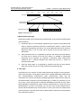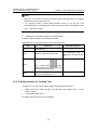
1
Chapter 1 Overview of Traffic Measurement .................................................
1-1
1.1 Basic Concepts and Terminology ...........................................................
1.1.1 Definition ........................................................................................
1.1.2 Terms Related to Traffic Measurement Modes..............................
1.1.3 Terms Related to Traffic Measurement Operations .......................
1-1
1-1
1-1
1-1
1.2 Basic Principles ......................................................................................
1.2.1 Working Process ............................................................................
1.2.2 Time Properties..............................................................................
1.2.3 State Transition ..............................................................................
1.3 Functional Features ................................................................................
1.3.1 Task Function ................................................................................
1.3.2 Exception Report ...........................................................................
1.3.3 Brief Report ....................................................................................
1.3.4 Sampling Measurement .................................................................
1.3.5 Measurement Report Incredible .....................................................
1.3.6 Screening measurement of Caller ID Display (CID) numbers .......
1.3.7 Outputting Measurement Result in Call Record Mode ...................
1.3.8 No loss of Measurement Tasks in Case of Switchover and
Reloading ................................................................................................
1.3.9 Dynamical Modification of Tasks ...................................................
1.3.10 Display and Storage of Measurement Results .............................
1.3.11 User-Defined Entity ......................................................................
1-5
1-5
1-6
1-8
1-9
1-9
1-9
1-10
1-10
1-10
1-11
1-11
Chapter 2 Traffic Measurement Tasks ...........................................................
2-1
2.1 Overview ................................................................................................
2.2 Total Traffic of the Office Task ...............................................................
2.2.1 Functions .......................................................................................
2.2.2 Measurement Units ........................................................................
2.3 Bearer Traffic Task .................................................................................
2.3.1 Functions .......................................................................................
2.3.2 Measurement Units ........................................................................
2.4 Global Component Task .........................................................................
2.4.1 Functions .......................................................................................
2.4.2 Measurement Units ........................................................................
2.5 Signaling and Interface Task ..................................................................
2.5.1 Functions .......................................................................................
2.5.2 Measurement Units ........................................................................
2.6 Call Record Task ....................................................................................
2.6.1 Functions .......................................................................................
2.6.2 Measurement Units ........................................................................
2-1
2-1
2-1
2-2
2-4
2-4
2-5
2-8
2-8
2-8
2-8
2-8
2-9
2-12
2-12
2-12
1-11
1-11
1-11
1-12
2.7 Maximum/Minimum Value Task .............................................................
2.7.1 Functions .......................................................................................
2.7.2 Measurement Units ........................................................................
2.8 Intelligent Service Task ..........................................................................
2.8.1 Functions .......................................................................................
2.8.2 Measurement Units ........................................................................
2-13
2-13
2-13
2-14
2-14
2-14
Chapter 3 Traffic Measurement Operations ..................................................
3-1
3.1 Overview ................................................................................................
3.1.1 Operation Procedures ....................................................................
3.1.2 Logging in to Traffic Measurement System ...................................
3.1.3 Points for Attention .........................................................................
3.2 Creating Measurement Task ..................................................................
3.2.1 Customizing Entity .........................................................................
3.2.2 Entering Interface for Creating Task ..............................................
3.2.3 Inputting Task Name and Description ............................................
3.2.4 Selecting Task Type ......................................................................
3.2.5 Selecting Measurement Unit ..........................................................
3.2.6 Selecting Measurement Entities ....................................................
3.2.7 Selecting Measurement Object(s) ..................................................
3.2.8 Setting Time Properties .................................................................
3.2.9 Defining Entity Threshold ...............................................................
3.2.10 Defining Sampling Parameters and Report Output Mode............
3.2.11 Measurement Task Status ...........................................................
3.3 Querying or Dumping Measurement Task Result ..................................
3.3.1 Querying Measurement Task Result .............................................
3.3.2 Dumping Measurement Task Result ..............................................
3.4 Querying Information of Measurement Task ..........................................
3.5 Modifying Configurations of Measurement Task ....................................
3.6 Deleting Measurement Task ..................................................................
3.7 Activating/Deactivating Measurement Task ...........................................
3.8 Setting Clear Time for Maximum/Minimum Value Task .........................
3-1
3-1
3-2
3-3
3-4
3-5
3-9
3-10
3-10
3-11
3-11
3-14
3-15
3-17
3-19
3-20
3-21
3-21
3-26
3-27
3-28
3-30
3-30
3-31
Chapter 4 Traffic Measurement Applications ...............................................
4-1
4.1 Equipment Running Management ..........................................................
4.1.1 Checking Running Condition of All Equipment ..............................
4.1.2 Querying Call Loss .........................................................................
4.1.3 Distributing Busy Traffic .................................................................
4.1.4 Balancing Traffic ............................................................................
4.1.5 Searching Maximum/Minimum Value ............................................
4.2 Troubleshooting for Equipment ..............................................................
4-1
4-1
4-2
4-4
4-5
4-6
4-7
4.3 Monitoring and Maintenance for Network ...............................................
4.3.1 Measuring Inner Traffic and Outgoing/Incoming Traffic of Local
Office .......................................................................................................
4.3.2 Measuring Transit Traffic in Transit Office .....................................
4.3.3 Measuring National Toll Traffic ......................................................
4.3.4 Measuring Traffic of a User............................................................
4.3.5 Measuring Each Call ......................................................................
4.3.6 Measuring Calls to a Destination ...................................................
4.3.7 Measuring Traffic of an Office Direction .........................................
4.3.8 Measuring Traffic of a Trunk Group ...............................................
4.3.9 Measuring Traffic of a Centrex Group ............................................
4.3.10 Measuring Traffic of a PBX Group ...............................................
4.3.11 Measuring MGW Traffic ...............................................................
4-8
4-8
4-8
4-9
4-9
4-9
4-10
4-11
4-11
4-12
4-12
4-12
Chapter 5 Traffic Measurement Entities ........................................................
5-1
5.1 Total Traffic of the Office Task ...............................................................
5.2 Bearer Traffic Task .................................................................................
5.3 Global Component Task .........................................................................
5.4 Signaling and Interface Task ..................................................................
5.5 Call Record Task ....................................................................................
5.6 Maximum/Minimum Value Task .............................................................
5.7 Intelligent Service Task ..........................................................................
5-1
5-19
5-34
5-34
5-57
5-66
5-71
Chapter 6 Handling of Common Problems ...................................................
6-1
6.1 Operation-related Problems ...................................................................
6.1.1 How to Select a Traffic Measurement Task ...................................
6.1.2 How to Select a Measurement Unit ...............................................
6.1.3 How to Select a Measurement Object ...........................................
6.1.4 How to Determine an Output Entity ...............................................
6.2 Application-related Problems .................................................................
6.2.1 When to Output the Traffic Measurement Results .........................
6.2.2 How to Understand Period-Crossing Traffic Measurement ...........
6.2.3 Measurement Methods for Seizure Times, Seizure Traffic and
Average Seizure Duration and Their Relations.......................................
6.2.4 Some Special Cases of Traffic Measurement ................................
6.2.5 Inaccurate Traffic Measurement Caused by Modification of
Trunk Group Data ...................................................................................
6.2.6 Causes for Incomplete Traffic Measurement .................................
6.2.7 Use of the Service Quality Traffic Measurement ...........................
6.2.8 Precautions in Using Max/Min Value Traffic Measurement ...........
6.2.9 Why "Answer Times + Failure Times < Number of Call
Attempts (Seizures)" ...............................................................................
6.2.10 Traffic Measurement during Version Upgrade .............................
6-1
6-1
6-1
6-2
6-3
6-3
6-3
6-4
6-5
6-7
6-7
6-8
6-8
6-9
6-9
6-9
Appendix A List of Traffic Measurement Commands ..................................
A-1
Appendix B Acronyms and Abbreviations ....................................................
B-1
HUAWEI
U-SYS SoftX3000 SoftSwitch System
Operation Manual - Traffic Measurement
V300R001
U-SYS SoftX3000 SoftSwitch System
Operation Manual
Volume
Traffic Measurement
Manual Version
T2-011674-20040809-C-3.06
Product Version
V300R001
BOM
31160874
Huawei Technologies Co., Ltd. provides customers with comprehensive technical support
and service. Please feel free to contact our local office or company headquarters.
Huawei Technologies Co., Ltd.
Address: Administration Building, Huawei Technologies Co., Ltd.,
Bantian, Longgang District, Shenzhen, P. R. China
Postal Code: 518129
Website: http://www.huawei.com
Email: [email protected]
Copyright © 2004 Huawei Technologies Co., Ltd.
All Rights Reserved
No part of this manual may be reproduced or transmitted in any form or by any
means without prior written consent of Huawei Technologies Co., Ltd.
Trademarks
, HUAWEI, C&C08, EAST8000, HONET,
, ViewPoint, INtess, ETS, DMC,
TELLIN, InfoLink, Netkey, Quidway, SYNLOCK, Radium,
M900/M1800,
TELESIGHT, Quidview, Musa, Airbridge, Tellwin, Inmedia, VRP, DOPRA, iTELLIN,
HUAWEI OptiX, C&C08 iNET, NETENGINE, OptiX, iSite, U-SYS, iMUSE, OpenEye,
Lansway, SmartAX, infoX, TopEng are trademarks of Huawei Technologies Co.,
Ltd.
All other trademarks mentioned in this manual are the property of their respective
holders.
Notice
The information in this manual is subject to change without notice. Every effort has
been made in the preparation of this manual to ensure accuracy of the contents, but
all statements, information, and recommendations in this manual do not constitute
the warranty of any kind, express or implied.
About This Manual
Release Notes
The manual applies to U-SYS SoftX3000 SoftSwitch System V300R001.
Related Manuals
The related manuals are listed in the following table.
Manual
Content
U-SYS SoftX3000 SoftSwitch System
Technical Manual-System Description
It provides an overall introduction to SoftX3000, including
product features, applications and technical specifications.
U-SYS SoftX3000 SoftSwitch System
Technical Manual-Architecture &
Principle
It details on the hardware architecture, component
interworking mechanism, and subsystems of alarm, billing,
and clock in SoftX3000.
U-SYS SoftX3000 SoftSwitch System
Maintenance Manual-Routine
Maintenance
It guides the maintenance engineers to perform daily
maintenance, monthly maintenance, and yearly
maintenance tasks on equipment.
U-SYS SoftX3000 SoftSwitch System
Maintenance Manual-Emergency
Maintenance
It guides the maintenance engineers to perform recovery
operations in the case of emergencies, such as congestion
of global service, AMG, and TMG, and failure of host and
BAM.
U-SYS SoftX3000 SoftSwitch System
Maintenance Manual-Parts
Replacment
It guides the maintenance engineers on how to replace
hardware components such as boards, fan frame, LAN
Switch, and hard disk.
U-SYS SoftX3000 SoftSwitch System
Hardware Installation Manual
It details the installation procedure of SoftX3000 hardware
components, and matters needing attention during the
installation process.
U-SYS SoftX3000 SoftSwitch System
Software Installation Manual
It covers the detailed procedure of installing SoftX3000
software, including BAM server, emergency workstation
and client, focusing on the key points that might cause
installation failure.
U-SYS SoftX3000 SoftSwitch System
Operation Manual-Traffic
Measurement
It guides the engineers how to perform traffic measurement
operations and how to analyze traffic measurement results.
U-SYS SoftX3000 SoftSwitch
System Operation ManualConfiguration Guide
It guides the engineers how to configure various data in
SoftX3000, including configuration steps, preparations,
database table referencing relationships, and command
parameters.
U-SYS SoftX3000 SoftSwitch System
Operation Manual-Configuration
It guides the engineers how to configure various data in
SoftX3000, including networking example, configuration
Manual
Content
Example
script, key parameters and debugging guidance.
U-SYS SoftX3000 SoftSwitch System
Operation Manual-Service Application
It covers the voice services, IP Centrex services,
multi-media services, IN services and value added services
supported by SoftX3000, focusing on the meaning,
operations, example and points for attention of various
services.
U-SYS iGateway Bill User Manual
It elaborates on the functioning principle of the iGateway
Bill. Also, it teaches you on how to install, maintain, and
operate the product.
Organization
The manual describes the traffic measurement operations and applications in
SoftX3000 V300R001.
There are six chapters and two Appendixes in the manual.
z
Chapter 1 Overview of Traffic Measurement introduces common concepts for
traffic measurement, structure, working principles and basic functions of the traffic
measurement system in SoftX3000.
z
Chapter 2 Traffic Measurement Tasks introduces various traffic measurement
tasks in SoftX3000 and the measurement units they contain.
z
Chapter 3 Traffic Measurement Operations details the methods and
procedures for various traffic measurement operations in the GUI of the traffic
measurement system.
z
Chapter 4 Traffic Measurement Applications details the main applications of
the traffic measurement system, such as fault locating and traffic balancing.
z
Chapter 5 Traffic Measurement Entities presents the meaning, measurement
point and measurement formula of various traffic measurement entities in
SoftX3000.
z
Chapter 6 Handling of Common Problems presents the faults that might occur
during traffic measurement and the corresponding handling methods.
z
Appendix A List of Traffic Measurement Commands lists the MML commands
for traffic measurement operations and their specific meanings.
z
Appendix B Acronyms and Abbreviations lists the main abbreviations used in
this manual and the corresponding full expressions.
Intended Readers
The manual is intended for the following readers:
z
NGN network planning experts
z
NGN network administrators
z
NGN system engineers
Conventions
The manual uses the following conventions:
I. General conventions
Convention
Description
Arial
Normal paragraphs are in Arial.
Arial Narrow
Warnings, Cautions, Notes and Tips are in Arial Narrow.
Boldface
Headings are in Boldface.
II. Command conventions
Convention
Boldface
Description
The keywords of a command line are in Boldface.
III. GUI conventions
Convention
Description
<>
Button names are inside angle brackets. For example, click the <OK>
button.
[]
Window names, menu items, data table and field names are inside
square brackets. For example, pop up the [New User] window.
/
Multi-level menus are separated by forward slashes. For example,
[File/Create/Folder].
IV. Mouse operation
Action
Description
Click
Press the left button or right button quickly (left button by default).
Double Click
Press the left button twice continuously and quickly.
V. Symbols
Eye-catching symbols are also used in the manual to highlight the points worthy of
special attention during the operation. They are defined as follows:
Caution Means reader be extremely careful during the operation.
Note Means a complementary description.
Operation Manual - Traffic Measurement
U-SYS SoftX3000 SoftSwitch System
Table of Contents
Table of Contents
Chapter 1 Overview of Traffic Measurement .............................................................................. 1-1
1.1 Basic Concepts and Terminology ...................................................................................... 1-1
1.1.1 Definition ................................................................................................................. 1-1
1.1.2 Terms Related to Traffic Measurement Modes....................................................... 1-1
1.1.3 Terms Related to Traffic Measurement Operations................................................ 1-1
1.2 Basic Principles.................................................................................................................. 1-5
1.2.1 Working Process ..................................................................................................... 1-5
1.2.2 Time Properties ....................................................................................................... 1-6
1.2.3 State Transition ....................................................................................................... 1-8
1.3 Functional Features ........................................................................................................... 1-9
1.3.1 Task Function.......................................................................................................... 1-9
1.3.2 Exception Report..................................................................................................... 1-9
1.3.3 Brief Report ........................................................................................................... 1-10
1.3.4 Sampling Measurement ........................................................................................ 1-10
1.3.5 Measurement Report Incredible............................................................................ 1-10
1.3.6 Screening measurement of Caller ID Display (CID) numbers .............................. 1-11
1.3.7 Outputting Measurement Result in Call Record Mode ......................................... 1-11
1.3.8 No loss of Measurement Tasks in Case of Switchover and Reloading ................ 1-11
1.3.9 Dynamical Modification of Tasks........................................................................... 1-11
1.3.10 Display and Storage of Measurement Results.................................................... 1-11
1.3.11 User-Defined Entity ............................................................................................. 1-12
Chapter 2 Traffic Measurement Tasks ........................................................................................ 2-1
2.1 Overview ............................................................................................................................ 2-1
2.2 Total Traffic of the Office Task........................................................................................... 2-1
2.2.1 Functions................................................................................................................. 2-1
2.2.2 Measurement Units ................................................................................................. 2-2
2.3 Bearer Traffic Task ............................................................................................................ 2-4
2.3.1 Functions................................................................................................................. 2-4
2.3.2 Measurement Units ................................................................................................. 2-5
2.4 Global Component Task .................................................................................................... 2-8
2.4.1 Functions................................................................................................................. 2-8
2.4.2 Measurement Units ................................................................................................. 2-8
2.5 Signaling and Interface Task ............................................................................................. 2-8
2.5.1 Functions................................................................................................................. 2-8
2.5.2 Measurement Units ................................................................................................. 2-9
2.6 Call Record Task ............................................................................................................. 2-12
2.6.1 Functions............................................................................................................... 2-12
i
Operation Manual - Traffic Measurement
U-SYS SoftX3000 SoftSwitch System
Table of Contents
2.6.2 Measurement Units ............................................................................................... 2-12
2.7 Maximum/Minimum Value Task....................................................................................... 2-13
2.7.1 Functions............................................................................................................... 2-13
2.7.2 Measurement Units ............................................................................................... 2-13
2.8 Intelligent Service Task.................................................................................................... 2-14
2.8.1 Functions............................................................................................................... 2-14
2.8.2 Measurement Units ............................................................................................... 2-14
Chapter 3 Traffic Measurement Operations ............................................................................... 3-1
3.1 Overview ............................................................................................................................ 3-1
3.1.1 Operation Procedures ............................................................................................. 3-1
3.1.2 Logging in to Traffic Measurement System ............................................................ 3-2
3.1.3 Points for Attention.................................................................................................. 3-3
3.2 Creating Measurement Task ............................................................................................. 3-4
3.2.1 Customizing Entity .................................................................................................. 3-5
3.2.2 Entering Interface for Creating Task ....................................................................... 3-9
3.2.3 Inputting Task Name and Description................................................................... 3-10
3.2.4 Selecting Task Type.............................................................................................. 3-10
3.2.5 Selecting Measurement Unit ................................................................................. 3-11
3.2.6 Selecting Measurement Entities............................................................................ 3-11
3.2.7 Selecting Measurement Object(s)......................................................................... 3-14
3.2.8 Setting Time Properties......................................................................................... 3-15
3.2.9 Defining Entity Threshold ...................................................................................... 3-17
3.2.10 Defining Sampling Parameters and Report Output Mode .................................. 3-19
3.2.11 Measurement Task Status .................................................................................. 3-20
3.3 Querying or Dumping Measurement Task Result ........................................................... 3-21
3.3.1 Querying Measurement Task Result..................................................................... 3-21
3.3.2 Dumping Measurement Task Result..................................................................... 3-26
3.4 Querying Information of Measurement Task ................................................................... 3-27
3.5 Modifying Configurations of Measurement Task ............................................................. 3-28
3.6 Deleting Measurement Task............................................................................................ 3-30
3.7 Activating/Deactivating Measurement Task .................................................................... 3-30
3.8 Setting Clear Time for Maximum/Minimum Value Task .................................................. 3-31
Chapter 4 Traffic Measurement Applications............................................................................. 4-1
4.1 Equipment Running Management ..................................................................................... 4-1
4.1.1 Checking Running Condition of All Equipment ....................................................... 4-1
4.1.2 Querying Call Loss .................................................................................................. 4-2
4.1.3 Distributing Busy Traffic .......................................................................................... 4-4
4.1.4 Balancing Traffic...................................................................................................... 4-5
4.1.5 Searching Maximum/Minimum Value...................................................................... 4-6
4.2 Troubleshooting for Equipment.......................................................................................... 4-7
4.3 Monitoring and Maintenance for Network.......................................................................... 4-8
4.3.1 Measuring Inner Traffic and Outgoing/Incoming Traffic of Local Office.................. 4-8
ii
Operation Manual - Traffic Measurement
U-SYS SoftX3000 SoftSwitch System
Table of Contents
4.3.2 Measuring Transit Traffic in Transit Office .............................................................. 4-8
4.3.3 Measuring National Toll Traffic ............................................................................... 4-9
4.3.4 Measuring Traffic of a User..................................................................................... 4-9
4.3.5 Measuring Each Call ............................................................................................... 4-9
4.3.6 Measuring Calls to a Destination .......................................................................... 4-10
4.3.7 Measuring Traffic of an Office Direction................................................................ 4-11
4.3.8 Measuring Traffic of a Trunk Group ...................................................................... 4-11
4.3.9 Measuring Traffic of a Centrex Group................................................................... 4-12
4.3.10 Measuring Traffic of a PBX Group ...................................................................... 4-12
4.3.11 Measuring MGW Traffic ...................................................................................... 4-12
Chapter 5 Traffic Measurement Entities...................................................................................... 5-1
5.1 Total Traffic of the Office Task........................................................................................... 5-1
5.2 Bearer Traffic Task .......................................................................................................... 5-19
5.3 Global Component Task .................................................................................................. 5-34
5.4 Signaling and Interface Task ........................................................................................... 5-34
5.5 Call Record Task ............................................................................................................. 5-57
5.6 Maximum/Minimum Value Task....................................................................................... 5-66
5.7 Intelligent Service Task.................................................................................................... 5-71
Chapter 6 Handling of Common Problems ................................................................................. 6-1
6.1 Operation-related Problems............................................................................................... 6-1
6.1.1 How to Select a Traffic Measurement Task ............................................................ 6-1
6.1.2 How to Select a Measurement Unit......................................................................... 6-1
6.1.3 How to Select a Measurement Object .................................................................... 6-2
6.1.4 How to Determine an Output Entity......................................................................... 6-3
6.2 Application-related Problems............................................................................................. 6-3
6.2.1 When to Output the Traffic Measurement Results.................................................. 6-3
6.2.2 How to Understand Period-Crossing Traffic Measurement .................................... 6-4
6.2.3 Measurement Methods for Seizure Times, Seizure Traffic and Average Seizure
Duration and Their Relations ........................................................................................... 6-5
6.2.4 Some Special Cases of Traffic Measurement......................................................... 6-7
6.2.5 Inaccurate Traffic Measurement Caused by Modification of Trunk Group Data..... 6-7
6.2.6 Causes for Incomplete Traffic Measurement .......................................................... 6-8
6.2.7 Use of the Service Quality Traffic Measurement .................................................... 6-8
6.2.8 Precautions in Using Max/Min Value Traffic Measurement .................................... 6-9
6.2.9 Why “Answer Times + Failure Times < Number of Call Attempts (Seizures)”........ 6-9
6.2.10 Traffic Measurement during Version Upgrade ...................................................... 6-9
Appendix A List of Traffic Measurement Commands................................................................A-1
Appendix B Acronyms and Abbreviations .................................................................................B-1
iii
Operation Manual - Traffic Measurement
U-SYS SoftX3000 SoftSwitch System
Chapter 1 Overview of Traffic Measurement
Chapter 1 Overview of Traffic Measurement
1.1 Basic Concepts and Terminology
1.1.1 Definition
Traffic statistics, also called “traffic measurement”, “payload measurement” or
“performance measurement”, refers to various measuring activities carried out on
softswitch equipment and communication networks around the switch to obtain such
measurement data as running status, signaling, users and system resources. It aims to
providing reliable data basis for operation management and fault location of equipment,
as well as monitoring & maintenance, planning & design of networks.
1.1.2 Terms Related to Traffic Measurement Modes
I. Measurement Task
It describes a group of operations set by operator or system for a specific traffic
measurement. Such descriptions cover multiple aspects, such as measurement object
feature, measurement time, output entity, and output time.
II. Measurement Subtask
It refers to the tasks with the same attributes but with different measurement objects.
For example, the traffic measurement task to measure the traffic of two Media
Gateways (MGWs) contains two subtasks.
III. Deactivate Measurement Task
It is one of the traffic measurement operations and used to stop an ongoing traffic
measurement task, hence no more result will be outputted. In this case, the task itself is
not deleted and only the system resources that it occupies are released.
IV. Activate Measurement Task
It is a reverse operation of deactivating a measurement task, which resumes a
suspended traffic measurement task, and SoftX3000 will continue to output the
measurement result.
1.1.3 Terms Related to Traffic Measurement Operations
I. Measurement Unit
It is a specific measurement category, for example, “Fixed User Originating Traffic”,
“Sort Fixed User Originating Traffic”, and “Fixed Inner Traffic”. It can be fully described
1-1
Operation Manual - Traffic Measurement
U-SYS SoftX3000 SoftSwitch System
Chapter 1 Overview of Traffic Measurement
by such elements as entity, object, time and output arrangement. It gives answers to
such questions as what to be measured, when the measurement will begin, how to
measure it, when and where the measurement result will be outputted.
II. Measurement Task Type
It is also called “measurement subset” or “measurement unit set”. It is a collection of
measurement units with certain same attributes.
For instance, the measurement unit set of “Maximum/Minimum Value Task” is
composed of such measurement units as “Top Called Busy Traffic”, “Top Call Loss
Traffic”, “Top Usage User Traffic”, “Top Ringed No Answer Traffic” and “Top Idle TK
Circuit Traffic”.
III. Measurement Object
It is a physical or logical entity or a combination of various entities to be measured, such
as destination code and MGW.
IV. Measurement Entity
It is also called “measurement item”. It is a specific parameter (for example, seizure
times, answer traffic) for which data must be collected during the traffic measurement.
V. Original Entity
It is an entity already defined in SoftX3000, that is,SoftX3000 has defined the formula
for collecting data for the entity such as call attempt times and seizure traffic.
Contradictory to original entity, it is user-defined entity.
VI. Measurement Type
It is a specific combination of measurement entities and measurement objects, for
example, trunk group traffic and number of outgoing calls.
VII. Measurement Set
It is a whole collection of measurement types that can be fulfilled by a specific traffic
measurement system.
VIII. Entity Threshold
It is a preset standard for evaluating an entity, usually including two values: the upper
threshold and the lower threshold. If the entity value goes beyond the upper or lower
threshold value, an alarm will be given.
The upper and lower thresholds can be set as needed. If only the upper threshold of an
entity is concerned, the lower threshold can be set to 0. Likewise, if only the lower
threshold is concerned, the upper threshold can be set to 0.
1-2
Operation Manual - Traffic Measurement
U-SYS SoftX3000 SoftSwitch System
Chapter 1 Overview of Traffic Measurement
Caution:
Not all entities have the threshold attribute. Thresholds can only be set for entities with the threshold
attribute.
IX. Restriction
It refers to the conditions of screening measurement objects in a measurement unit, for
example, “The calls from which originating terminals should be measured” (“originating
terminals” for short), “The calls to which terminating terminals should be measured”
(“terminating terminals” for short). Only the calls meeting all restrictions of a specific
measurement unit can be counted into the measurement result of this measurement
unit.
Generally, each measurement unit has 1~5 restrictions. Different measurement units
vary in their restrictions.
For example, connection type measurement unit has restrictions on connection type,
which can be national toll outgoing traffic, national toll incoming traffic, national toll
tandem traffic, international toll outgoing traffic, international toll incoming traffic,
international toll tandem traffic, intra-office traffic, local originating outgoing traffic, local
incoming terminating traffic and local transit traffic. Whereas fixed user originating
traffic measurement unit has no restrictions.
X. Object Type
It is used to describe a specific restriction. Generally, each restriction can have several
optional object types, but only one object type can be selected to describe the
restriction.
For example, in the restriction of “a certain user”, there are three object types:
z
User external code = DN set + telephone number.
z
User internal code = Fixed Calling Control Unit (FCCU)/Fixed Calling control unit
and Signaling process Unit (FCSU) number + user type + user logical number.
z
User port = FCCU/FCSU number + user equipment + port number.
XI. Object Value
It refers to the selected object type, for example, “user number” is an object value.
XII. Measurement Period
It is the cyclic period for a specific measurement task and can be set in day, week or
month.
1-3
Operation Manual - Traffic Measurement
U-SYS SoftX3000 SoftSwitch System
Chapter 1 Overview of Traffic Measurement
XIII. Measurement Time Segment
It refers to the start and end time of a measurement task in a day, for example,
9:00-10:30.
XIV. Output Period
It refers to the period of outputting the measurement result of a measurement task, for
example, every 1 minute, every 10 minutes or every 15 minutes.
XV. Output Transmission Information
It is a parameter recording to which target measurement results are sent.
XVI. Output Arrangement Information
It is a parameter specifying when to output measurement results.
XVII. Traffic Measurement Report
It describes the results of the traffic measurement of a certain type, including
measurement object, measurement entity value, measurement period, start and end
time of a measurement task, so as to provide basis for further measurement, planning,
running and management of the performances in the entire office and network.
The following is an example showing the application of these concepts, and briefly
describing the way to create a traffic measurement task. Suppose it is required to
measure the completion rate of incoming toll calls to the local office.
z
Create a traffic measurement task to measure the completion rate of incoming toll
calls. This means to specify the “measurement unit”. There are nearly 100
measurement units in SoftX3000. To facilitate search and application, these
measurement units are classified into seven measurement unit sets. To locate a
measurement unit, first you should know to which measurement unit set it belongs.
In this example, select the measurement unit of “Office Direction Incoming Office
Traffic” in the measurement unit set of “Bearer Traffic Task”.
z
Once the measurement unit is created, the measurement object is thus specified.
In this example, the measurement object is “Incoming Direction”. Note that one
traffic measurement task must correspond to at least one measurement object.
Otherwise, the traffic measurement task makes no practical sense.
z
Specify the range of the measurement object. In this example, specify the number
of the toll office direction that is connected to the local switch. The office direction
number selected here becomes a restriction, and the measurement of the
completion rate of incoming toll calls of a specific office is a subtask.
z
The traffic measurement task in this example contains 28 entities to be measured,
such as Answer Times, Answer Traffic, Seizure Times, Seizure ratio, Connected
Times, Connected Traffic and Connection Ratio. You can select desired entities to
be outputted, thus simplifying the traffic measurement report.
1-4
Operation Manual - Traffic Measurement
U-SYS SoftX3000 SoftSwitch System
z
Chapter 1 Overview of Traffic Measurement
Finally, specify the time information and output arrangement information.
In a word, all kinds of traffic measurement tasks can be easily created as long as you
have grasped such basic concepts as measurement unit set, measurement unit,
measurement object, measurement entity and measurement period.
1.2 Basic Principles
1.2.1 Working Process
As a software application system, SoftX3000’s traffic measurement system is
composed of Statistics process of Back Administration Module (BAM) and traffic
measurement sub-modules distributed in host software of such service boards as
FCCU, FCSU, Broadband Signaling
Gateway Unit (BSGI), Multimedia Signaling
Gateway Unit (MSGI), IP Forward Module (IFMI), and Media Resource Control Unit
(MRCA).
Its logical structure is as shown in Figure 1-1.
Equipment data
Signaling data
Equipment data
Signaling data
Protocol data
Traffic
measurement
sub-mocule
Service board n
Call processing
data
Traffic
measurement
sub-mocule
Service board1
Call processing
data
Protocol data
Host
BAM
Worksataion
1
Workstation
n
Figure 1-1 Logical structure of traffic measurement system
Note:
The workstation on which you can maintain SoftX3000 remotely through iWEB also supports traffic
measurement operations, which are implemented in the same way as on ordinary workstations.
1-5
Operation Manual - Traffic Measurement
U-SYS SoftX3000 SoftSwitch System
Chapter 1 Overview of Traffic Measurement
In SoftX3000, traffic measurement functions are accomplished by traffic measurement
sub-modules distributed in the host software of various service boards. Figure 1-1
illustrates the working process as follows:
1)
The maintenance personnel sets a traffic measurement task on the workstation
first. This task is then sent through SMUI and shared resource bus to the traffic
measurement sub-modules of corresponding service boards by the Statistics
process of BAM.
2)
Next, the traffic measurement sub-modules collect original traffic measurement
data such as call processing data, equipment data, signaling data and protocol
data, and return the results to BAM.
3)
Subsequently, the Statistics process of BAM saves and arranges the structure of
traffic measurement data.
4)
Finally, the maintenance personnel can check on the workstation the traffic
measurement results stored in BAM.
1.2.2 Time Properties
Time properties refer to all the information required for the setting of start time, end time
and period for a specific measurement. You can set different time schedules. Time
information can be classified into the levels and categories as shown in Figure 1-2
depending on different settings of start time, duration and period.
All the time
Continuous monitoring and recording
Continuous recording
Basic time
types for
measurement
Based on cycle
Duration pre-defined
Recording within pre-defined duration
Not based on cycle
Continuous recording
Duration not defined
Recording within pre-defined duration--based on cycle
Figure 1-2 Levels and categories of time properties
Note:
Traffic measurement can be carried out with/without duration (end time) pre-defined, or continuously, or
periodically, or irregularly.
Time properties include task type, time type, measurement period and measurement
duration. The management of measurement time can be achieved in the following
three levels: time type, measurement duration and measurement period, as shown in
Figure 1-3.
1-6
Operation Manual - Traffic Measurement
U-SYS SoftX3000 SoftSwitch System
Date
Chapter 1 Overview of Traffic Measurement
Date
Date
Date
Date
Date
Date
Date
Time type
Measurement
time segment
0:00
24:00
Measurement cycle
Figure 1-3 Basic time types
I. Measurement task type
Measurement tasks can be divided into permanent task, semi-permanent task and task
with finite period.
1)
Permanent task: It is automatically registered by the system during startup and
used to measure important performance measurement entities. A report will be
generated if requested by the carrier. You cannot delete this task, that is, since the
equipment starts to run, the task will be carried out all the time unless it is
deactivated.
2)
Semi-permanent task: It is registered by operator and without end time defined.
The task will be carried out all the time unless it is deleted or deactivated
temporarily by the operator. For example, a permanent traffic measurement
created on Oct. 1, 2003 but started to be carried out from Nov. 1, 2003 is a
semi-permanent task.
3)
Task with finite period: It is registered by operator and with end time defined.
When the end time arrives, the measurement will stop automatically.
II. Time type
It specifies the cyclic mode of a traffic measurement task during its running duration.
There are three types, namely daily measurement, weekday-dependent measurement
and
month-dependent
measurement.
Daily
measurement
means
that
the
measurement is carried out everyday. Weekday-dependent measurement means that
the measurement is carried out at the specified days in a week. For example, you can
set to carry out the measurement on Monday, Wednesday and Friday of every week.
Month-dependent measurement means that the measurement is carried out at the
specified days in a month. For example, you can set to carry out the measurement on
the first, fifth and thirteenth day of every month. In each cyclic mode, the measurement
will be carried out in the daily time mode co-determined by measurement time segment
and measurement period.
1-7
Operation Manual - Traffic Measurement
U-SYS SoftX3000 SoftSwitch System
Chapter 1 Overview of Traffic Measurement
III. Measurement time segment
SoftX3000 allows you to divide each day into three time segments at maximum, but no
overlap between them is allowed. Within the predefined time segments, measurement
will be carried out based on the preset measurement period and will stop between the
time segments. Measurement time segment and measurement period co-determine
the time mode for daily running of a task.
1)
The measurement starts at 00:00 and ends at 24:00 every day.
2)
One to three uncontinuous time segments are set for the measurement and each
time segment starts at a specified time (precise to minute). The measurement will
last for several consecutive periods.
IV. Measurement period
It is also the sampling period for a measurement. Traffic measurement management
system can create measurement task with period of 1-1440 minutes.
1)
It is set in unit of minute and cannot exceed 24 hours.
2)
It is set to 15 minutes by default.
1.2.3 State Transition
A traffic measurement task might undergo four states within its life cycle, as shown in
Figure 1-4.
Non-started state
Start time arrives
Deactivate
Deactivated state
Activated state
Activate
End time arrives
Finished state
Figure 1-4 State transition diagram of a traffic measurement task
Note:
According to the definitions of different tasks:
z
A permanent task will undergo activated or deactivated state.
z
A semi-permanent task might undergo non-started, activated or deactivated state.
z
A task with finite period might undergo any of the four states.
1-8
Operation Manual - Traffic Measurement
U-SYS SoftX3000 SoftSwitch System
1)
Chapter 1 Overview of Traffic Measurement
Non-started state: It means that the current time of the system is earlier than the
start time of a task, that is to say, the task is not started.
2)
Activated state: It means that the current time of the system is between the start
time and end time of a task, that is, the task is being carried out.
3)
Deactivated state: When a task is not needed for the time being, it can be
deactivated and no measurement result will be outputted. In case of future need,
the deactivated task can be activated again. A deactivated task cannot be
modified.
4)
Finished state: It means that the current time of the system is later than or equals
to the end time of a task, that is to say, the task has ended.
1.3 Functional Features
1.3.1 Task Function
It includes creating/deleting a measurement task (subtask), adding/deleting the
measurement objects of a measurement task, setting/deleting the entity threshold of a
measurement task, modifying/activating/deactivating a measurement task, querying
the information and status of a measurement task.
SoftX3000 supports a maximum of 128 measurement tasks and 512 measurement
subtasks. Subtasks are allocated dynamically among the tasks. Creation of a new task
will fail once there have already been 512 subtasks. Only after an existing task is
deleted and the resources are released, can a new task be created. Moreover,
SoftX3000 allows you to deactivate a task (subtask) that is being carried out. Once a
task is deactivated, the occupied resources will be released, and no more
measurement result will be outputted. That is, it enters the dormant status. However, it
can be reactivated. Subtasks are extremely effective for trunk group traffic
measurement. You can use a single task to measure the traffic of all trunk groups, and
set to output the measurement results in the reports based on respective objects.
Once a task is created, you can add or delete its measurement objects. This feature
makes it possible to add a new object or delete an existing object without deleting the
created task. For example, if it is required to add one more measurement object for a
task that already has several objects, you can use this function.
Moreover, you can quickly create and flexibly select the traffic measurement tasks by
activating and deactivating the tasks. Normally the frequently used traffic measurement
tasks can be fulfilled at one time. You can deactivate these tasks when they are not
required, and activate them again when needed by just modifying the attributes such as
time.
1.3.2 Exception Report
It refers to the measurement result report that is outputted when the measurement
value of the entity is beyond the upper/lower threshold during the measurement. The
1-9
Operation Manual - Traffic Measurement
U-SYS SoftX3000 SoftSwitch System
Chapter 1 Overview of Traffic Measurement
report prompts you of abnormal measurement values of some entities, actually
reflecting some potential abnormalities in SoftX3000. You can analyze the cause of the
abnormal measurement values based on the report, so as to eliminate such
abnormalities accordingly.
1.3.3 Brief Report
This function determines which entities can be outputted and which cannot. It enables
you to delete the unconcerned entities from the output report, thus making the report
brief and concise.
1.3.4 Sampling Measurement
Some special measurement units have the function of sampling measurement, which
belong to such measurement unit sets as call records or traffic distribution. They are
characterized by extremely large capacity of call measuring, and generally the
measurement effect can be shown through sampling measurement. Moreover,
sampling measurement is advantageous in saving the system resources and improving
the measurement efficiency. For example, “Destination Distribution Traffic” measures
the traffic of all destination codes in the office direction. This measurement is fulfilled in
a task-matching mode and consumes a lot of system resources. If many tasks of this
kind are registered and no sampling processing is performed, SoftX3000 will probably
be short of resources.
There are two kinds of sampling measurement, sampling ratio and sampling times.
Sampling ratio refers to the measurements of a certain proportion of calls randomly
sampled in the whole measurement set. For example, 30% means sampling 3 from 10
calls, or 300 from 1 000 calls for measurement. Sampling times refers to the
measurements of a specific number of calls randomly sampled in the whole
measurement set, beyond this number, there will be no further sampling and the
measurement will end. For example, “Dispersion Duration Traffic” can be measured in
either sampling ratio mode or sampling times mode; whereas “Destination Distribution
Traffic” can only be measured in sampling ratio mode, and the default sampling ratio
and sampling times are “100%” and “all”.
1.3.5 Measurement Report Incredible
This function marks in the result report whether the measurement result is accurate or
not, so as to remind you of the credibility of the measurement activity. The incredible
measurement result is caused by many factors, for instance, the system time or
measurement period is modified, configuration data is set, the counter is reset, or the
result is received incompletely during the measurement.
1-10
Operation Manual - Traffic Measurement
U-SYS SoftX3000 SoftSwitch System
Chapter 1 Overview of Traffic Measurement
1.3.6 Screening measurement of Caller ID Display (CID) numbers
This feature allows setting of restrictions, so as to measure the CID numbers which
meet specific requirements. For example, to measure the number of incoming calls and
traffic of CID numbers with the prefix "654" from a specific trunk group to the local
office.
1.3.7 Outputting Measurement Result in Call Record Mode
After the screening conditions are specified, the time and activities of the calls meeting
the conditions in various call stages will be recorded, which is equivalent to the function
of connection tracing which can be automatically recorded and screened.
1.3.8 No loss of Measurement Tasks in Case of Switchover and Reloading
This feature ensures a measurement task not to be interrupted by maintenance
operations. This is important to the traffic measurement tasks with a long measurement
period.
Caution:
If switchover or reloading occurs in a specific period, the measurement result in this period will be affected.
For example, a traffic measurement task (Task 1) with the period of one hour and a traffic measurement
task (Task 2) with the period of 24 hours are created in a certain office. If SoftX3000 is reset at 10:10, the
report of Task 1 between 10:00~11:00 is marked as “result received incompletely” and the report of Task 2
on that very day is so marked too.
1.3.9 Dynamical Modification of Tasks
It includes the modification of measurement time, addition/deletion of measurement
object, and modification of the threshold set in exception report. Once a task is modified,
it can be carried out with the new requirements from the next measurement period.
1.3.10 Display and Storage of Measurement Results
SoftX3000 provides a traffic measurement window, where you can view the traffic
measurement results conveniently. SoftX3000 also supports the printing of traffic
measurement tasks and results. You can first save the detailed information about the
traffic measurement tasks and results in a text file, then print out the text file. Or you can
print the traffic measurement results directly through the report print function.
1-11
Operation Manual - Traffic Measurement
U-SYS SoftX3000 SoftSwitch System
Chapter 1 Overview of Traffic Measurement
1.3.11 User-Defined Entity
This feature allows you to define new entities in addition to the original entities to meet
various measurement demands. You can define an entity in two ways: recombination of
the original entities and creation of completely new entities. Both ways are realized by
designing new entity calculation formula.
1-12
Operation Manual - Traffic Measurement
U-SYS SoftX3000 SoftSwitch System
Chapter 2 Traffic Measurement Tasks
Chapter 2 Traffic Measurement Tasks
2.1 Overview
You can subscribe various traffic measurement data needed to SoftX3000, which form
different measurement tasks. The following traffic measurement tasks are available in
SoftX3000:
z
Total Traffic of the Office Task;
z
Bearer Traffic Task;
z
Global Component Task;
z
Signaling and Interface Task;
z
Call Record Task;
z
Maximum/Minimum Value Task;
z
Intelligent Service Task.
2.2 Total Traffic of the Office Task
2.2.1 Functions
This task functions in measuring the main eight traffic flows (as shown in Figure 2-1)
and corresponding connection types, so as to output such information as calling status
of the entire office, calling QoS and network quality to facilitate traffic balancing and
error-correction.
It features “global” measurement, and its measurement object is usually “all users” “all
incoming or bi-directional circuits” or “all outgoing or bi-directional circuits” and so on.
2-1
Operation Manual - Traffic Measurement
U-SYS SoftX3000 SoftSwitch System
E
User of local office
A
Chapter 2 Traffic Measurement Tasks
{
}C
G
B
User of local office
H
}D
{
Inter-office user
A: Originating traffic
D: Outgoing traffic
G: Originating outgoing traffic
F
Inter-office user
B: Incoming traffic
E: Local traffic
H: Terminating incoming traffic
C: Terminating traffic
F: Transit traffic
Figure 2-1 Schematic diagram of traffic flows
2.2.2 Measurement Units
This task contains thirteen measurement units as listed in Table 2-1.
Table 2-1 Measurement units of “Total Traffic of the Office Task”
Measurement unit
Meaning
Measurement object
It measures the basic data of calls
originated by fixed users in the local
office.
FIXED_USER_ORIGINA
TING_TRAFFIC
If the called user is also a user in the
local office, this measurement unit
corresponds
to
FIXED_INNER_TRAFFIC.
If the called user is an inter-office
user, this measurement unit
corresponds
to
FIXED_USER_ORIGINATING_OU
TGOING_OFFICE_TRAFFIC.
All fixed users, including Ethernet
Subscriber Line (ESL) users,
H.323 users, Session Initiation
Protocol (SIP) users and
attendant console
SORT_FIXED_USER_O
RIGINATING_TRAFFIC
It measures the basic data of calls
originated by all fixed users of a
specified type in an office.
All fixed users of a certain type,
including ESL users, H.323
users, SIP users and attendant
console
FIXED_INNER_TRAFFIC
It measures the basic data of calls
originated by fixed users in the local
office to other fixed users in the
same office.
All fixed users, including ESL
users, H.323 users, SIP users
and attendant console
FIXED_USER_ORIGINA
TING_OUTGOING_OFFI
CE TRAFFIC
It measures the basic data of calls
originated by fixed users in the local
office to inter-office users.
All fixed users, including ESL
users, H.323 users, SIP users
and attendant console
2-2
Operation Manual - Traffic Measurement
U-SYS SoftX3000 SoftSwitch System
Measurement unit
Chapter 2 Traffic Measurement Tasks
Meaning
Measurement object
It measures the basic data of calls
originated by inter-office users.
INCOMING_OFFICE_TR
AFFIC
If the called user is a fixed user in
the local office, this measurement
unit
corresponds
to
INCOMING_OFFICE_TERMINATI
NG_TRAFFIC.
All incoming and bi-directional
circuits
If the called user is an inter-office
user, this measurement unit
corresponds
to
TRANSFER_TRAFFIC.
INCOMING_OFFICE_TE
RMINATING_TRAFFIC
It measures the basic data of calls
originated by inter-office users to
fixed users in the local office.
All incoming and bi-directional
circuits
TRANSFER_TRAFFIC
It measures the basic data of calls
originated by inter-office users to
other inter-office users.
All incoming and bi-directional
circuits
It measures the basic data of calls
received by fixed users in the local
office.
FIXED_TERMINATING_T
RAFFIC
If the calling user is an inter-office
fixed user, this measurement unit
corresponds
to
INCOMING_OFFICE_TERMINATI
NG_TRAFFIC.
All fixed users, including ESL
users, H.323 users, SIP users
and attendant console
If the calling user is a fixed user in
the local office, the measurement
unit corresponds to Fixed Inner
Traffic.
FIXED_TERMINATING_T
RAFFIC
It measures the basic data of calls
received by all fixed users of a
specified type in an office.
All fixed users of a certain type,
including ESL users, H.323
users, SIP users and attendant
console
It measures the basic data of calls
received by inter-office users.
OUTGOING_OFFICE_TR
AFFIC
If the calling user is a fixed user in
the local office, this measurement
unit
corresponds
to
FIXED_USER_ORIGINATING_OU
TGOING_OFFICE TRAFFIC.
If the calling user is an inter-office
user, the measurement unit
corresponds
to
TRANSFER_TRAFFIC.
2-3
All outgoing and bi-directional
circuits
Operation Manual - Traffic Measurement
U-SYS SoftX3000 SoftSwitch System
Measurement unit
Chapter 2 Traffic Measurement Tasks
Meaning
Measurement object
CONNECTING_TYPE_T
RAFFIC
It measures the basic data of all
connections of a specified type in an
office.
The options are outgoing national
toll, incoming national toll,
transfer national toll, outgoing
international
toll,
incoming
international
toll,
transfer
international toll, internal call,
originating outgoing local call,
incoming terminating local call
and transfer local call. These
connection types can be
combined flexibly based on
actual needs. For example,
outgoing national toll, incoming
national toll and transfer national
toll can be selected for the
measurement of toll connections.
FAILURE_REASON_TRA
FFIC
It provides more than 100 call failure
reasons.
All call failure reasons
ALL_OFFICES_SUM_TR
AFFIC
It measures the basic data of all
calls in the local office.
All fixed users (including ESL
users, H.323 users, SIP users
and attendant console)
2.3 Bearer Traffic Task
2.3.1 Functions
This task functions in measuring traffic bearer objects such as trunk, destination code,
user and MGW. These objects, especially the performance entities of these object
groups (for instance, trunk group, office direction, each destination code, destination
and user), affect the calling performance greatly. In addition, they are the basic data
necessary for network maintenance and planning.
Therefore, this task supports automatic measurement of each object group and report
of measurement results at any time. Besides measurement of object groups, it also
supports measurement of single objects, such as single user, single trunk circuit, single
Centrex group and single Private Automatic Branch eXchange (PABX) group, in order
to facilitate fault location and observation of a specified object’s performance.
Measurement of each single object consumes a lot of resources and it is also
unnecessary, so you can select only some objects to measure.
1)
Destination code refers to the number dialed by user, which can be country code,
area code, softswitch office number, user number or special service number.
2)
Destination refers to the number of a prefix in the called number analysis table,
which is defined when you add a call prefix. Generally a destination can
correspond to multiple destination codes.
2-4
Operation Manual - Traffic Measurement
U-SYS SoftX3000 SoftSwitch System
Chapter 2 Traffic Measurement Tasks
Either destination code or destination can be selected as measurement object. In the
former case, the dialed number is matched directly; while in the latter case, number
match is carried out after analysis. Under some situations (for example, there is an
outgoing prefix prior to a destination code), only destination can be selected as
measurement object.
For example, destination code 201 corresponds to destination 1. Create two bearer
traffic tasks on destination code 201 and destination 1 respectively. When a user dials
“0201” (“0” is the outgoing prefix), because “0201” does not match with the destination
code, this call cannot be measured if the destination code is selected as the
measurement object. However, after number analysis, the number matches with the
destination 1, so this call can be measured if the destination is selected as the
measurement object.
2.3.2 Measurement Units
This task contains eighteen measurement units as listed in Table 2-2.
Table 2-2 Measurement units of “Bearer Traffic Task”
Measurement unit
Meaning
Measurement object
OFFICE_DIRECTION_IN
COMING_OFFICE_TRAF
FIC
It measures the traffic born by
incoming circuits in each office
direction and the running state
of outgoing circuits. In addition,
it can trace the calls from
opposite office to the local
office. By cooperation among
multiple offices, trace of the
whole process of a call can be
achieved.
All incoming and bi-directional circuits
in each office direction
OFFICE_DIRECTION_O
UTGOING_OFFICE_TRA
FFIC
It measures the traffic born by
outgoing circuits in each office
direction and the running state
of outgoing circuits, so as to
provide
reference
for
maintenance and network
management.
All outgoing and bi-directional circuits
in each office direction
TKGRP_INCOMING_OF
FICE_TRAFFIC
It measures the traffic born by
incoming circuits of each trunk
group.
Combination of any incoming or
bi-directional trunk groups, or of trunk
group sets
TKGRP_OUTGOING_OF
FICE_TRAFFIC
It measures the traffic born by
outgoing circuits of each trunk
group.
Combination of any outgoing or
bi-directional trunk groups, or of trunk
group sets
2-5
Operation Manual - Traffic Measurement
U-SYS SoftX3000 SoftSwitch System
Chapter 2 Traffic Measurement Tasks
Measurement unit
Meaning
DESTINATION_TRAFFIC
It measures the traffic to a
certain destination, so as to
provide reference data for
network management and
maintenance,
to
help
maintenance personnel find the
cause for low call completion
ratio, to improve network
management and control
capability and to allocate
network
resources
more
efficiently.
Measurement object
One or several destinations
Combination of objects, consisting of
two parts:
(1) One or more destinations (or
destination codes), or all destination
codes (that is, only office direction or
trunk group is taken into
consideration. In this case, the
measurement
is
similar
to
“OFFICE_DIRECTION_OUTGOING
_OFFICE_TRAFFIC”
or
“TKGRP_OUTGOING_OFFICE_TRA
FFIC”)
DESTINATION_DISTRIB
UTION_TRAFFIC
It measures the distribution of
traffic to a certain destination
code in an office direction.
(2) Combination of any office
directions, or trunk groups, or all
outgoing trunk groups, or all objects
(that is, only destination or destination
code is taken in consideration. In this
case, the measurement is similar to
“DESTINATION_TRAFFIC”)
Note:
(1) The above two parts are
compulsory. If any part is required to
be ignored, “all…” must be selected
for this part (for example, all objects).
(2) Only outgoing calls can be
measured for this measurement unit.
One or multiple users, who can be
described in the following ways:
SINGLE_USER_TRAFFI
C
It measures the originating and
terminating traffic of a single
user.
(1) User internal code = module
number + user type + user logical
number. User types include ESL user,
SIP user and H.323 user.
(2) User external code = DN set +
telephone number
User port = module number + user
equipment + port number
2-6
Operation Manual - Traffic Measurement
U-SYS SoftX3000 SoftSwitch System
Measurement unit
Chapter 2 Traffic Measurement Tasks
Meaning
Measurement object
PABXGRP_TRAFFIC
It measures the traffic of a
group of users associated
physically and logically, so as to
obtain such information about
number allocation and resource
occupation.
Each PBX group
CENTREX_INTRA-GRO
UP_TRAFFIC
It measures the traffic between
users of a certain IP Centrex
group.
A certain IP Centrex group
CENTREX_EXTRA-GRO
UP_TRAFFIC
It measures the calls originated
by out-group users to users of
an IP Centrex group.
A certain IP Centrex group
It
measures
the
calls
(occupying trunks) originated by
users of an IP Centrex group to
out-group users.
A certain IP Centrex group
CENTREX_OUTGOING_
GROUP_TRAFFIC
Combination of objects, consisting of
two parts:
(1) Combination of any IP Centrex
groups
SUPPLEMENTARY_SER
VICE_CENTREX_TRAFF
IC
It measures the registration,
cancellation and verification of a
supplementary service or all
supplementary services in an IP
Centrex group.
(2)
Combination
of
any
supplementary services such as
abbreviated dialing, hotline service,
alert service, or all supplementary
services
Note:
The above two parts are compulsory.
If supplementary service is required to
be ignored, “all supplementary
services” must be selected for this
part.
SUPPLEMENTARY_SER
VICE_TRAFFIC
It measures the registration,
cancellation and verification of a
supplementary service or all
supplementary services of all
users in an IP Centrex group.
Combination of any supplementary
services such as abbreviated dialing,
hotline service and alert service
ISDN_BEARER_SERVIC
E_TRAFFIC_MEASURE
MENT
It measures the traffic of all
Integrated Services Digital
Network (ISDN) users for each
ISDN bearer service.
Combination of any ISDN bearer
services, which can be divided into
local ISDN services and V5 ISDN
services, including voice services,
audio services, and digital services
It measures the traffic of a
single primary rate interface of
ISDN.
One or more ISDN primary rate
interfaces (described in form of
“module number + ISDN type +
Primary Rate Adaptation (PRA)
interface”; ISDN can be divided into
local ISDN and V5 ISDN)
ISDN_PRIMARY_RATE_I
NTERFACE_TRAFFIC_M
EASUREMENT
2-7
Operation Manual - Traffic Measurement
U-SYS SoftX3000 SoftSwitch System
Chapter 2 Traffic Measurement Tasks
Measurement unit
Meaning
Measurement object
TRUNK_GROUP_OF_IN
TERLINK_OFFICE_INCO
MING_TRAFFIC
It measures the traffic born by
incoming circuits of each trunk
group at the interconnection
point.
Combination of any incoming or
bi-directional trunk groups, or of any
trunk group sets
TRUNK_GROUP_OF_IN
TERLINK_OFFICE_OUT
GOING_TRAFFIC
It measures the traffic born by
outgoing circuits of each trunk
group in an interconnected
office.
Combination of any outgoing or
bi-directional trunk groups, or of any
trunk group sets
MGW_TRAFFIC
It measures the traffic of an
MGW, so as to obtain the
running state of it.
Combination of any gateways
2.4 Global Component Task
2.4.1 Functions
Global components are components serving for call connection but are not associated
with specific call processing procedure after call completion. Global components are
shared by a lot of calls, and the quantity and performance of them directly affect the call
completion ratio and other key entities, therefore, measurement of traffic and
congestion times of them can provide basic information for improving Quality of Service
(QoS).
2.4.2 Measurement Units
This task contains only one measurement unit as listed in Table 2-3.
Table 2-3 Measurement unit of “Global Component Task”
Measurement unit
Meaning
Measurement object
CPU_SEIZURE_R
ATIO_TRAFFIC
It measures the Central Processing Unit (CPU)
occupation rate of each module and provides data
of originating calls, terminating calls and overflow
calls for calculation of Busy Hour Call Attempts
(BHCA) processing capability.
Any combination of SMUI,
IFMI, FCCU, FCSU,
BSGI, MSGI, MRCA and
CDBI (described in form
of “module number”)
2.5 Signaling and Interface Task
2.5.1 Functions
This task functions in measuring the traffic of various signaling and interfaces, so as to
facilitate analyzing the performance of signaling and interfaces, obtaining cooperation
state between inter-office signaling and user signaling as well as network status, and
2-8
Operation Manual - Traffic Measurement
U-SYS SoftX3000 SoftSwitch System
Chapter 2 Traffic Measurement Tasks
providing reference data for running and maintenance of SoftX3000 and peripheral
networks.
2.5.2 Measurement Units
This task contains thirty-seven measurement units as listed in Table 2-4.
Table 2-4 Measurement units of “Signaling and Interface Task”
Measurement unit
Meaning
Measurement object
H248_MGW_STATISTIC
It measures the traffic of H.248 MGW.
A H.248 MGW
H323_RAS_MESSAGE_M
EASUREMENT
It measures the traffic of H.323
Registration, Admission and Status
(RAS) messages.
None
H323_Q931_MESSAGE_
MEASUREMENT
It measures the traffic of H.323 Q.931
messages.
None
H323_H245_MESSAGE_M
EASUREMENt
It measures the traffic of H.323 H.245
messages.
None
ISDN_SIGNALING_TRAFF
IC_MEASUREMENT
It measures the traffic of ISDN
signaling communication channel (D
channel).
D channel
MTP_SIGNALING_LINK_
MEASUREMENT
It measures the traffic of Message
Transfer Part (MTP) signaling link(s).
One or more MTP signaling
links (described in form of
“module number + link ID”)
MTP_LINKSET_TRAFFIC
It measures the traffic of MTP
signaling link set(s).
One or more MTP signaling
link sets
MTP_DEST_SIGNALING_
POINT_TRAFFIC
It measures the traffic of MTP
Destination Signaling Point (DSP)
(including inaccessible times and
duration).
DSPs of one or more MTPs
(described in form of “Network
Indicator (NI) + Destination
Point Code (DPC)”, where NI
can be international network,
international standby network,
national network or national
standby network)
ISUP_TOTAL_MSU_TRAF
FIC
It measures the traffic of Integrated
Services Digital Network User
Part/ISDN User Part (ISUP).
All ISUPs
ISUP_MSG_USING_TRAF
FIC
It measures the traffic of an ISUP
trunk group for receiving and sending
a certain type of ISUP messages.
One or several types of ISUP
messages (described in form
of “ISUP trunk group + ISUP
message
type”,
where
message
types
include
Address Complete Message
(ACM), Address No complete
Message (ANM), Blocking
signal (BLO))
ISUP_ABNORMITY_TRAF
FIC
It measures the abnormity traffic of
ISUP trunk group.
One or more ISUP trunk
groups
2-9
Operation Manual - Traffic Measurement
U-SYS SoftX3000 SoftSwitch System
Chapter 2 Traffic Measurement Tasks
Measurement unit
Meaning
ISUP_NODE_PERFORMA
NCE_TRAFFIC
It measures the traffic of all ISUP
nodes.
All ISUPs
ISUP_NET_PERFORMAN
CE_TRAFFIC
It measures the number of all types of
messages received by ISUP network.
Some or all Originating
signaling Point Codes (OPCs)
ISUP_CIRCUIT_GRP_PE
RFORMANCE_TRAFFIC
It measures the traffic of ISUP circuit
group, including number of received
messages and status of circuit group.
One or more ISUP trunk
groups
SCCP_PERFORMANCE_
STATISTIC
It measures the route conversion
performance of Signaling Connection
Control Part (SCCP), that is, the
number of routing failures due to
various causes.
Signaling point index of the
local office
SCCP_AVAILABILITY_ST
ATISTIC
It measures the availability of SCCP,
that is, the number and duration of
SCCP failures due to various causes.
Signaling point index of local
office
SCCP_UTILIZATION_STA
TISTIC
It measures the utilization of SCCP,
that is, the number of messages
received or sent by SCCP.
Signaling point index of the
local office
TCAP_AVAILABILITY_ST
ATISTIC
It measures the availability of
Transaction Capabilities Application
Part (TCAP), that is, the number and
duration of TCAP failures due to
various causes.
Global statistic
TCAP_COMPONENT_UTI
LIZATION_STATISTIC
It measures the utilization of various
components of TCAP.
Global statistic
TCAP_MESSAGE_UTILIZ
ATION_STATISTIC
It measures the number of messages
received and sent by TCAP.
Global statistic
TCAP_TRANSACTION_S
UBLAYER_PERFORMAN
CE_STATISTIC
It measures the performance of TCAP
transaction sub-layer.
Global statistic
IUA_SIGNALING_LINK_T
RAFFIC
It measures the traffic and state
messages of an ISDN Q.921-User
Adaptation Layer (IUA) signaling link.
A certain IUA signaling link
IUA_LINKSET_FLUX_TRA
FFIC
It measures the traffic of an IUA
signaling link set.
A certain IUA signaling link set
IUA_LINKSET_STATE_TR
AFFIC
It measures the state traffic of an IUA
signaling link set.
A certain IUA signaling link set
M2UA_LINK_TRAFFIC
It measures the traffic, congestion
duration
and
link
connection/disconnection times of a
Message Transfer Part 2 (MTP2)
-User Adaptation Layer (M2UA) link.
A certain M2UA link
(described in form of “BSGI
module number + M2UA link
number”)
2-10
Measurement object
Operation Manual - Traffic Measurement
U-SYS SoftX3000 SoftSwitch System
Chapter 2 Traffic Measurement Tasks
Measurement unit
Meaning
Measurement object
M3UA_DESTINATION_EN
TITY_TRAFFIC
It measures the inaccessibility times
and duration of a Message Transfer
Part 3 (MTP3) -User Adaptation Layer
(M3UA) destination entity.
A certain M3UA destination
entity
M3UA_LINKSET_FLUX_T
RAFFIC
It measures the traffic of an M3UA link
set, such as total number of
messages sent or received. The
measurement items of an M3UA link
set are the total of those of all M3UA
links in one link set
A certain M3UA signaling link
set
M3UA_LINKSET_STATE_
TRAFFIC
It measures the state traffic of an
M3UA link set, such as unavailability
times and duration of the M3UA link
set.
A certain M3UA signaling link
set
M3UA_SIGNALING_LINK_
TRAFFIC
It measures the traffic, congestion
duration
and
link
connection/disconnection times of an
M3UA link.
A certain M3UA signaling link
(described in form of “BSGI
module number + M3UA link
number”)
SERVER_MGCP_MESSA
GE_STATISTIC
It measures the number of Media
Gateway Control Protocol (MGCP)
messages received and sent by
SoftX3000.
All MGWs
MGCP_ERROR_MESSAG
E_STATISTIC_FOR_SPE
CIFIC_MGW
It measures the types of MGCP error
messages of an MGW.
An MGW
MGW_MGCP_MESSAGE_
STATISTIC
It measures the number of MGCP
messages received and sent by an
MGW.
An MGW
MGCP_MESSAGE_TRAF
FIC_IN_A_SPECIFIC_MR
CA
It measures the number of MGCP
messages received and sent by an
MRCA.
A certain MRCA board
STUN_MESSAGE_MEAS
UREMENT
It measures the number of STUN
messages received and sent.
None
V5UA_SIGNALING_LINK_
TRAFFIC
It measures the traffic and state
messages of a V5.2-User Adaptation
Layer (V5UA) signaling link.
A certain V5UA signaling link
V5UA_LINKSET_FLUX_T
RAFFIC
It measures the traffic of a V5UA
signaling link set.
A certain V5UA signaling link
set
V5UA_LINKSET_STATE_
TRAFFIC
It measures the state traffic of a V5UA
signaling link set.
A certain V5UA signaling link
set
2-11
Operation Manual - Traffic Measurement
U-SYS SoftX3000 SoftSwitch System
Chapter 2 Traffic Measurement Tasks
2.6 Call Record Task
2.6.1 Functions
This task functions in recording the details of some calls so as to reflex the performance
and resource consumption of SoftX3000 in different stages of call processing and to
provide reference for optimizing and evaluating SoftX3000’s call processing
performance. Because of enormous quantity of calls, measurement of all call attempts
will cause extremely heavy load to various resources of SoftX3000. Therefore, in order
to reduce the quantity of call records, the measurement can be carried out by sampling
or restricting various features of calls in details.
2.6.2 Measurement Units
This task contains four measurement units as listed in Table 2-5.
Table 2-5 Measurement units of “Call Record Task”
Measurement unit
COMPLETE_RATI
O_TRAFFIC
Meaning
It measures the
completion ratio.
Measurement object
call
All users and trunks
Combination of objects, consisting of five parts:
(1) Some or all inlets (calling users), described
by inlet user Message Identification (MID) group,
inlet User Identification (UID) group and others.
(2) Some or all outlets (called users), described
by outlet user MID group, outlet UID group and
others.
DISPERSION_DU
RATION_TRAFFIC
It measures the
processing details.
call
(3) Some or all call attributes, including local call,
local toll call, national automatic call, and
international automatic call.
(4) Some or all destination codes (destinations).
(5) Some or all calling numbers.
Note that all the above parts are mandatory. If
any part is required to be ignored, “all…” must be
selected for this part (for example, all call
attributes).
MULTI_CONDITIO
N_OBJECT_TRAF
FIC
It measures the traffic of
combination of multiple
objects.
2-12
Same as above
Operation Manual - Traffic Measurement
U-SYS SoftX3000 SoftSwitch System
Measurement unit
Chapter 2 Traffic Measurement Tasks
Meaning
Measurement object
Combination of objects, consisting of five parts:
(1) Some or all inlets (calling users), described
by inlet user MID group, inlet UID group and
others.
SERVICE_QUALIT
Y_TRAFFIC
It measures the quality of
service provided to users
by analyzing the call
processing process.
(2) Some or all outlets (called users), described
by outlet user MID group, outlet UID group and
others.
(3) Some or all call attributes, including local call,
local toll call, national automatic call, and
international automatic call.
(4) Some or all destination codes (destinations).
(5) Some or all calling numbers.
Note that all the above parts are mandatory. If
any part is required to be ignored, “all…” must be
selected for this part (for example, all destination
numbers).
2.7 Maximum/Minimum Value Task
2.7.1 Functions
This task functions in measuring the maximum or minimum values (ten values will be
outputted by default) so as to facilitate maintenance and error location and to improve
call completion rate.
2.7.2 Measurement Units
This task contains five measurement units as listed in Table 2-6.
Table 2-6 Measurement units of “Maximum/Minimum Value Task”
Measurement unit
Meaning
Measurement object
Set of threshold users:
TOP_CALLED_BU
SY_TRAFFIC
It measures the traffic of top busy
called users in a user group or in the
local office, providing reference data
for distributing busy traffic,
enhancing call completion rate and
improving QoS.
(1) Combination of any Centrex groups.
(2) Users sorted by FCCU/FCSU
module number.
(3) Users sorted by type, that is, any
combination of user types.
(4) All users.
TOP_CALL_LOSS
_TRAFFIC
It measures the traffic of users with
highest call loss in a user group or in
the local office, providing reference
data for distributing busy traffic,
enhancing call completion rate and
improving QoS.
2-13
Set of threshold users, who can be
grouped in the same way as above.
Operation Manual - Traffic Measurement
U-SYS SoftX3000 SoftSwitch System
Chapter 2 Traffic Measurement Tasks
Measurement unit
Meaning
Measurement object
TOP_USAGE_USE
R_TRAFFIC
It measures the traffic of users who
are extremely busy in a user group or
in the local office, providing
reference data for distributing busy
traffic, enhancing call completion
rate and improving QoS.
Set of threshold users, who can be
grouped in the same way as above.
TOP_RINGED_NO
_ANSWER_TRAFF
IC
It measures the traffic of users with
top ringing no answer rate in a user
group or in the local office, providing
reference data for distributing busy
traffic, enhancing call completion
rate and improving quality of service.
Set of threshold users, who can be
grouped in the same way as above.
TOP_IDLE_TK_CI
RCUIT_TRAFFIC
It measures the traffic of top idle
trunk circuits in the local office,
providing reference data for
distributing busy traffic, enhancing
call completion rate and improving
quality of service.
Set of threshold trunk groups
2.8 Intelligent Service Task
2.8.1 Functions
This task functions in measuring Intelligent Network (IN) services, operations and
resources, so as to offer reference data for effective management of IN services and
proper allocation of IN resources.
2.8.2 Measurement Units
This task contains fourteen measurement units as listed in Table 2-7.
Table 2-7 Measurement units of “Intelligent Service Task”
Measurement unit
Meaning
Measurement object
INSM_OPERATION_MEAS
UREMENT
It measures the total number of Intelligent
Network Application Protocol (INAP)
operations in an office.
One or more service
keys
THE_TRAFFIC_MEASURE
MENT_FOR_FIN_CALL
It measures the IN call attempts and
seizure information in an office.
One or more service
keys
THE_TRAFFIC_MEASURE
MENT_FOR_FIN_CALL_IN_
QUALITY
It measures the IN call completion
information in an office.
One or more service
keys
IN_DIALOGUE_MEASURE
MENT
It measures IN dialogues in an office.
None
2-14
Operation Manual - Traffic Measurement
U-SYS SoftX3000 SoftSwitch System
Chapter 2 Traffic Measurement Tasks
Measurement unit
Meaning
Measurement object
FIN_EVENT_DP_MEASUR
EMENT
It measures the IN events in an office.
None
FIN_FAIL_MEASUREMENT
It measures the IN call failures in an office.
One or more service
keys
IN_FAIL_MEASUREMENT
It measures the causes for IN call failures
in an office.
None
FIN_OPERATION_MEASUR
EMENT
It measures the IN operations in an office.
None
THE_TRAFFIC_MEASURE
MENT_FOR_FIN_CALL_OU
T_QUALITY
It measures the IN outgoing call quality in
an office.
One or more service
keys
It measures the number of Service
Resource Function (SRF) operations.
A kind of resource used
by a certain service key
(described in form of
“module number +
service key + some SRF
source”)
SRF_TRAFFIC_MEASURE
MENT
It measures the SRF traffic
One or more service
keys (described in form
of “module number +
service key”)
SRM_OPERATION_MEASU
REMENT
It measures the occupation information of
SRM resources.
A certain service key
(described in form of
“module number +
service key”)
THE_MEASUREMENT_FO
R_FIN_USER_INTERACTIO
N
It measures the IN user interaction data.
One or more service
keys
MRF_GLOBAL_MRF_CHAN
NEL_TRAFFIC
It measures the occupation rate of
channels controlled by an MRCA.
MRCA module number
SRF_OPERATION_MEASU
REMENT
2-15
Operation Manual - Traffic Measurement
U-SYS SoftX3000 SoftSwitch System
Chapter 3 Traffic Measurement Operations
Chapter 3 Traffic Measurement Operations
3.1 Overview
3.1.1 Operation Procedures
You can implement traffic measurement by various task operations. Refer to the
following figure for the traffic measurement procedures. The operations in broken line
boxes are optional.
Start
Analyze traffice measurement demand
Create traffic measurement task
Start traffice measurement task
Query traffic measurement task
Modify traffic measurement task
List traffic measurement result
Deactivate traffic measurement task
Activate traffic measurement task
Traffic measurement task ends
Delete traffic measurement task
End
Figure 3-1 Traffic measurement procedures
3-1
Operation Manual - Traffic Measurement
U-SYS SoftX3000 SoftSwitch System
Chapter 3 Traffic Measurement Operations
Note:
Refer to Chapter 4, “Traffic Measurement Applications”, of this manual for analysis of traffic measurement
demands.
In the traffic measurement system, you can create, modify or delete traffic
measurement tasks, list the details of a traffic measurement task, query, save and print
traffic measurement result. Among these operations, the creation of a traffic
measurement task is a fundamental one, for other operations are carried out on already
created tasks.
3.1.2 Logging in to Traffic Measurement System
You can implement various traffic measurement operations in either Graphical User
Interface (GUI) or by Man Machine Language (MML).
I. Operations in GUI
1)
Click [Start/Programs/U-SYS SoftX3000 Statistics]. A dialog box for setting office
direction and IP address pops up.
2)
Click <Set> and input the office name and IP address. In the login window, select
the name of the office to be measured, and then input the correct account and
password. An interface as shown in Figure 3-2 appears.
Figure 3-2 GUI of traffic measurement operation system
II. Operations by MML
In Figure 3-3, you can input MML commands at the client.
3-2
Operation Manual - Traffic Measurement
U-SYS SoftX3000 SoftSwitch System
Chapter 3 Traffic Measurement Operations
Figure 3-3 Interface for MML command input
The above two modes serve the same purpose and achieve the same result. However,
GUI is clearer and easier for understanding and checking. The following section will
describe various operations in GUI.
3.1.3 Points for Attention
I. System resources
Each traffic measurement task occupies some system resources. The cases that too
many tasks are carried out simultaneously or too frequently will lead to resource
over-consumption, so a maximum of 128 tasks can be created.
II. User authority
The traffic measurement system divides user authorities into three levels: service query,
service setting and service management. The specific authorities of users of each level
are listed in Table 3-1.
Table 3-1 Table of user authorities
Operations
allowed
Users with service
query authority
Users with service
setting authority
Users with service
management authority
Creating a task
Prohibited
Allowed
Allowed
Deleting a task or
result
Prohibited
Allowed for the users who
have created the tasks to
be deleted
Allowed
3-3
Operation Manual - Traffic Measurement
U-SYS SoftX3000 SoftSwitch System
Operations
allowed
Chapter 3 Traffic Measurement Operations
Users with service
query authority
Users with service
setting authority
Users with service
management authority
Prohibited
Allowed for the users who
have created the tasks to
be modified
Allowed
Customizing
measurement
indices
Prohibited
Prohibited
Allowed
Querying a task
and result
Allowed
Allowed
Allowed
Modifying
name
task
III. Measurement entities
For any of extremum measurement entities of a measurement object, for example,
measurement of CPU occupation rate, it cannot be created in multiple measurement
tasks, otherwise, the measurement result will be inaccurate.
IV. BAM time
The result output of a traffic measurement task is closely related to the time. If the BAM
time is modified, it is possible that the measurement result exported within the first
measurement period after the modification will be incorrect.
3.2 Creating Measurement Task
Follow the steps as listed in Figure 3-4 to create a traffic measurement task:
3-4
Operation Manual - Traffic Measurement
U-SYS SoftX3000 SoftSwitch System
Chapter 3 Traffic Measurement Operations
Start
Customize entity or not?
Yes
Define entity thresholds
Customize entity
No
Define sampling
parameters
Input measurement task
name and description
infomation
Optional
Define report output mode
Select task type
End
Select measurement unit
Select measurement entities
Select measurement object(s)
Set measurement duration,
measurement periode and
measurement time segment
Figure 3-4 Steps for creating a traffic measurement task
Suppose it is required to create a task for measuring the traffic of IAD with the
requirements below:
z
Measurement entities include call attempts, seizure times, call connected times,
answer times, answer traffic, seizure traffic, connect traffic and customized no
answer times of IAD 0 and IAD1.
z
The measurement starts from Oct. 24, 2003 and lasts for 30 days. It is carried out
every five minutes between 9:00-11:00, 14:00-16:00, and 19:00-21:00 from
Monday to Friday.
z
When each measurement period ends, the report will be sent immediately to the
current workstation, traffic measurement port and Network Management System
(NMS) port.
The following sections present the detailed procedures for creating this task.
3.2.1 Customizing Entity
If the original entities of the system cannot meet the actual needs of a traffic
measurement task, you can customize an entity by following the steps as illustrated in
Figure 3-5.
3-5
Operation Manual - Traffic Measurement
U-SYS SoftX3000 SoftSwitch System
Chapter 3 Traffic Measurement Operations
Select measurement unit
Redefine original entity or
not?
Yes
No
Select [Define]
Input entity alias
Select [Redefine]
Select entity whose
calculation formula is
to be modified
Input entity name
Select entity unit
Select entity type
Select entity
Determine calculation
formula
Figure 3-5 Steps for customizing an entity
I. Entering the [Set Custom Entity] interface
There are two modes for entering the interface as shown in Figure 3-6:
z
Click [Entity/Set Custom Entity] in Figure 3-2.
z
Click the [Entity] tab to enter an interface as shown in Figure 3-2. Right click and
then click [Set Custom Entity] on the shortcut menu.
3-6
Operation Manual - Traffic Measurement
U-SYS SoftX3000 SoftSwitch System
Chapter 3 Traffic Measurement Operations
Figure 3-6 [Set Custom Entity] dialog box
II. Selecting a measurement unit based on the task
The measurement task “IAD traffic” corresponds to the measurement unit “MGW
Traffic”. Therefore, select “MGW Traffic” for [Measure Unit].
III. Determining a calculation formula for an entity
You can modify the calculation formula of an entity. Both definition of the formula of a
custom entity or modification of the formula of an original entity are allowed.
z
Determining a calculation formula for a custom entity
Follow the steps in Table 3-2 to define the formula.
Table 3-2 Steps for defining a calculation formula for a custom entity
Step
Step 1
Operations
Select [Define].
3-7
Parameter description
Operation Manual - Traffic Measurement
U-SYS SoftX3000 SoftSwitch System
Step
Step 2
Chapter 3 Traffic Measurement Operations
Operations
Parameter description
(1) Input alias and name of the custom
entity.
(2) Select unit and type of the custom
entity.
Step 3
Select the original measurement entity.
Step 4
Click a symbol among
(1) The length of entity alias cannot be
more than nine characters.
(2) Entity unit options include Millisecond,
%, Byte and No Unit.
(3) Entity type options include Integer,
Float, Time and BCD Code.
The measurement entity is determined by
the measurement unit.
,
select another original entity, and then
define the calculation formula for the
custom entity, as shown in Figure 3-7.
Step 5
Click <OK>. A prompt box indicating
“Operation succeeded” pops up. The
entity icon “mgw no answer times” will
appear in the [Entity] tab as shown in
Figure 3-2.
In the example, the custom entity “mgw no
answer times” = call connected times –
answer times.
Figure 3-7 Example of defining calculation formula for the custom entity
3-8
Operation Manual - Traffic Measurement
U-SYS SoftX3000 SoftSwitch System
Chapter 3 Traffic Measurement Operations
Note:
z
After step 4, if it is necessary to modify the calculation formula of the custom entity, you can directly
delete the formula and redefine a new one.
z
If it is required to modify an already defined calculation formula, you can right click on the
corresponding entity icon in the [Entity] tab as shown in Figure 3-2, and then click the [Modify Custom
Entity…] menu item to modify it.
z
Modifying the calculation formula of an original entity
Follow the steps in Table 3-3 to modify the formula.
Table 3-3 Steps for modifying the calculation formula of an original entity
Step
Operations
Step 1
Select [Redefine].
Step 2
Select the original measurement entity.
Step 3
Step 4
Parameter description
The measurement entity is
determined by the measurement
unit.
Click a symbol among
, select
another original entity, and then define the
calculation formula for the entity.
Click <OK>. A prompt box indicating
“Operation succeeded” pops up.
3.2.2 Entering Interface for Creating Task
In Figure 3-2, you can enter the task creation interface by three means.
z
Right click on the “Task List (All)” icon and then click [Create Task…] on the
shortcut menu.
z
Click [Task/Create Task…].
An interface as shown in Figure 3-8 appears.
3-9
Operation Manual - Traffic Measurement
U-SYS SoftX3000 SoftSwitch System
Chapter 3 Traffic Measurement Operations
Figure 3-8 Interface for creating a new task
3.2.3 Inputting Task Name and Description
The name of a traffic measurement task should be as simple and clear as possible, but
the description of it can contain the task purpose in details. The name should be a string
of less than 32 characters, consisting of English letters, digits and other characters.
Each Chinese character is counted as two characters, and no space between
characters is allowed.
In the example, set task name to “IADAnswerRate” and task description to “IAD 1
Answer Rate”.
3.2.4 Selecting Task Type
Each measurement entity is subject to related measurement task type and
measurement type. For a traffic measurement task, only measurement entities subject
to the same measurement task type can be selected, that is, all measurement entities
of a measurement task must belong to one or more measurement types of the same
measurement task type.
3-10
Operation Manual - Traffic Measurement
U-SYS SoftX3000 SoftSwitch System
Chapter 3 Traffic Measurement Operations
The measurement task “IAD traffic” corresponds to the measurement unit “MGW
Traffic” that is subject to “Bearer Traffic Task”, so select “Bear Traffic” for [Traffic Task
Type] in Figure 3-8.
3.2.5 Selecting Measurement Unit
Select “MGW Traffic” for [Measurement Unit] in Figure 3-8.
3.2.6 Selecting Measurement Entities
Caution:
If it is necessary to customize an entity, refer to 3.2.1.
In Figure 3-8, select the correct traffic task type and measurement unit, and then click
the [Entity] tab. The interface will be shown as in Figure 3-9.
3-11
Operation Manual - Traffic Measurement
U-SYS SoftX3000 SoftSwitch System
Chapter 3 Traffic Measurement Operations
Figure 3-9 Interface for selecting measurement entities
Note:
If custom entities exist, they will be shown in the [Available custom entity list:] field. The selection of custom
entities is in the same way as that of original entities.
Table 3-4explains the fields and buttons in the [Entity] tab.
Table 3-4 Meaning of fields and buttons in [Entity] tab
Field or button
Function
Available static entity list
It lists the original measurement entities defined in the system.
Selected static entity list
It lists the selected entities, indicating data should be collected for them.
3-12
Operation Manual - Traffic Measurement
U-SYS SoftX3000 SoftSwitch System
Chapter 3 Traffic Measurement Operations
Field or button
Function
It is used to add the measurement entities selected from the [Available
static entity list:] field to the [Selected static entity list] field.
Caution:
It is disabled unless you select a measurement entity from the [Available
static entity list:] field.
It is used to delete a selected measurement entity from the [Selected
static entity list] field.
Caution:
It is disabled unless you select a measurement entity from the [Selected
static entity list:] field.
It is used to add all the measurement entities listed in the [Available static
entity list:] field to the [Selected static entity list] field.
It is used to delete all measurement entities in the [Selected static entity
list] field.
It is disabled in creating a traffic measurement task, but enabled when
you modify properties of a task.
In the example, measurement entities include call attempts, seizure times, call
connected times, answer times, answer traffic, seizure traffic, connect traffic and
customized no answer times. After required measurement entities are selected, the
interface is as shown in Figure 3-10.
3-13
Operation Manual - Traffic Measurement
U-SYS SoftX3000 SoftSwitch System
Chapter 3 Traffic Measurement Operations
Figure 3-10 Interface showing selected measurement entities
3.2.7 Selecting Measurement Object(s)
Click the [Object] tab in Figure 3-8. An interface for selecting measurement object
appears.
Select or input the desired measurement object and add it into the measurement object
list.
In the example, first select “Certain MGW EID” for object type, and then input the ID
(that is, iad0.ngn1.com) of IAD 1 in the [Certain MGW EID] field. MGW EID can be
obtained by carrying out the LST MGW command. Finally, click <Add Object Instance>
to add the selected measurement object into the list, as shown in Figure 3-11.
3-14
Operation Manual - Traffic Measurement
U-SYS SoftX3000 SoftSwitch System
Chapter 3 Traffic Measurement Operations
Figure 3-11 Interface for selecting measurement object
Note:
z
For a traffic measurement task, multiple measurement objects can be selected, but you can only input
one object when inputting the measurement entity.
z
If it is necessary to add a measurement object, you can right click and then click [Add Measurement
Entity Instance] on the shortcut menu to add it. Refer to 3.5 for details.
3.2.8 Setting Time Properties
Click the [Time] tab in Figure 3-8. The interface will be shown as in Figure 3-12.
3-15
Operation Manual - Traffic Measurement
U-SYS SoftX3000 SoftSwitch System
Chapter 3 Traffic Measurement Operations
Figure 3-12 Interface for setting time properties
Table 3-5 explains the fields in the [Time] tab.
Table 3-5 Meaning of fields in [Time] tab
Field
Meaning
Value range
Remark
Start Date
It is used to specify the
date
when
a
measurement task is
started.
Any valid data. It is in the
format
of
Year-Month-Day,
for
example, 2003-10-23.
Current date is recommended.
1-1024 days
Selection can be made based
on need. If “StatisticsDuration”
is not checked, it indicates that
the traffic measurement task
will
be
carried
out
permanently.
Statistics
Duration
It is used to specify the
duration
of
a
measurement task.
3-16
Operation Manual - Traffic Measurement
U-SYS SoftX3000 SoftSwitch System
Field
Measure
Period
Chapter 3 Traffic Measurement Operations
Meaning
Value range
Remark
It is used to specify the
interval for outputting a
measurement result.
It can be one minute, five
minutes, ten minutes,
fifteen minutes, thirty
minutes, one hour or one
day.
By default, it is set to fifteen
minutes. Generally it is
recommended to set it to thirty
minutes or one hour.
Measure Every Day: The
measurement will be
carried out every day.
Measure
Date(s)
It is used to specify the
date(s)
for
measurement.
Measure Date(s) Every
Week: You can select
several weekdays for
measurement from the list
box.
Selection can be made based
on need.
Measure Date(s) Every
Month: You can select
several days in a month
for measurement from the
list box.
Measure
Time
Segment
It is used to specify the
time segment(s) in a day
for measurement.
1-3
Selection can be made based
on need.
It is used to set which
time
segment
is
effective.
Three positions
It can be dragged upward or
downward.
Start Time1
It is used to specify the
start time of the first time
segment.
00:00-24:00
Set the most concerned time
segment.
Start Time2
It is used to specify the
start time of the second
time segment.
00:00-24:00
It cannot be overlapped with
the first time segment.
Start Time3
It is used to specify the
start time of the third
time segment.
00:00-24:00
It cannot be overlapped with
the first and second time
segments.
In this example, set [Start Date] to “2003-10-24”, [Statistics Duration] to “30” days,
[Measure Date(s)] to “from Monday to Friday”, [Measure Time Segment] to “9:00-11:00”,
“14:00-16:00”, and “19:00-21:00”, and [Measure Period] to “5” minutes.
3.2.9 Defining Entity Threshold
Click the [Threshold] tab in Figure 3-8. The interface will be shown as in Figure 3-13.
In this tab, you can define lower threshold and upper threshold for a maximum of four
measurement entities. The upper and lower thresholds can be set as needed. If only
3-17
Operation Manual - Traffic Measurement
U-SYS SoftX3000 SoftSwitch System
Chapter 3 Traffic Measurement Operations
the upper threshold of an entity is concerned, the lower threshold can be set to 0.
Likewise, if only the lower threshold is concerned, the upper threshold can be set to 0.
Caution:
Not all measurement entities have thresholds, but only those with threshold property can be set with
thresholds. In this example, the measurement entities have no threshold.
Figure 3-13 Interface for defining entity threshold
Table 3-6 explains the fields and buttons in the [Threshold] tab.
Table 3-6 Meaning of fields and buttons in [Threshold] tab
Field
Entity Threshold List
Meaning
It lists the entities which can be set with threshold.
3-18
Operation Manual - Traffic Measurement
U-SYS SoftX3000 SoftSwitch System
Chapter 3 Traffic Measurement Operations
Field
Meaning
Lower Threshold
It is used to set the lower threshold of an entity.
Upper Threshold
It is used to set the upper threshold of an entity.
Set Threshold
By clicking this button, you can make the upper and lower
thresholds effective after they are set.
List of Thresholds which have been set
It lists the information of the entities whose thresholds have
been set.
Delete Threshold
After selecting an entity record in the [List of Thresholds
which have been set], you can click this button to delete the
thresholds of this entity.
3.2.10 Defining Sampling Parameters and Report Output Mode
Click the [Other] tab in Figure 3-8. The interface will be shown as in Figure 3-14.
Figure 3-14 Interface for defining sampling parameters and report output mode
3-19
Operation Manual - Traffic Measurement
U-SYS SoftX3000 SoftSwitch System
Chapter 3 Traffic Measurement Operations
Table 3-7 explains the fields in the [Other] tab.
Table 3-7 Meaning of fields in [Other] tab
Field
Sampling
Parameter
Meaning
Some measurement units generate two much information, so sampling
measurement is necessary to keep accuracy and reduce system burden to
some extent. By default, 100% is adopted for sampling rate. Note that not all
measurement units have sampling parameters.
It is used to set the destination where a measurement report will be sent. There
are three options:
Output Device
Current Workstation
Traffic Statistic Port
Network Manager Port
It is used to define the time when a measurement report will be exported. There
are three options:
Output
Arrangement
PerPeriod Output: When a measurement period ends, the report will be
exported immediately.
Specific Output: The report will be exported at specified time.
Over Threshold Output: Only when measurement value is beyond the threshold
range, will a report be exported.
In this example, when a measurement period ends, the system will immediately send
the traffic measurement report to the current workstation, traffic statistic port and
network manager port.
After all the parameters are set, click <OK>. If the task is created successfully, a new
node will appear under the [Task List (all)] node, as shown in Figure 3-15.
Figure 3-15 Interface showing successful creation of the task
3.2.11 Measurement Task Status
In Figure 3-15, “IADAnswerRate (Running)” indicates that this task is running currently.
Table 3-8 explains various status of traffic measurement task.
3-20
Operation Manual - Traffic Measurement
U-SYS SoftX3000 SoftSwitch System
Chapter 3 Traffic Measurement Operations
Table 3-8 Meaning of various status of traffic measurement task
Status
Meaning
Running
It indicates that a traffic measurement task is running currently.
Error
It indicates that a traffic measurement task is wrongly set.
Ended
It indicates that a traffic measurement task has ended.
Deactivated
It indicates that a traffic measurement task has been deactivated.
No objected instance
It indicates that a traffic measurement task has no measurement object.
Setup
It indicates that a traffic measurement task has been created successfully,
but the start time has not arrived set.
Undefined
It indicates that a traffic measurement task fails to be created in the host.
When a task is deactivated, it is deleted from the host, and its status will
be displayed as “Undefined”.
3.3 Querying or Dumping Measurement Task Result
3.3.1 Querying Measurement Task Result
I. Entering the interface for querying traffic measurement result
In the navigation tree as shown in Figure 3-2, select a desired task under the [Task
List(All)] node, right click on it and then click [Query Task Result…] on the shortcut
menu. An interface as shown in Figure 3-16 appears.
Caution:
When performing the [Query Task List] operation, if you select “All”, all tasks will be listed in the navigation
tree. If you select “Error task”, only error tasks will be listed.
3-21
Operation Manual - Traffic Measurement
U-SYS SoftX3000 SoftSwitch System
Chapter 3 Traffic Measurement Operations
Figure 3-16 [Query Task Result] dialog box
Table 3-9 explains the fields in the above dialog box.
Table 3-9 Meaning of fields in [Query Task Result] dialog box
Field
Meaning
Original: Only the result of the original measurement entities will be displayed.
Evolve: The result of the original measurement entities including those whose
calculation formulas have been modified will be displayed.
Entity Style
Brief: The result of the original measurement entities and custom measurement
entities will be displayed.
Detailed: The result of all measurement entities (including original measurement
entities, original measurement entities whose calculation formulas have been
modified and custom measurement entities) will be displayed.
Normal: The default report type of the system.
Sum by Period: The value of each measurement entity equals the total values of
all entities of the same type within the period.
Report Type
Sum by Object: The value of each measurement entity equals total values of all
entities of the same type for different measurement objects.
Sum by Period and Object: The value of each measurement entity equals total
values of all entities of the same type for different measurement objects with the
measurement period.
Threshold Overflow: Only the values of measurement entities that exceed the
threshold range will be displayed.
3-22
Operation Manual - Traffic Measurement
U-SYS SoftX3000 SoftSwitch System
Chapter 3 Traffic Measurement Operations
Field
Meaning
Continuous: The system will export results starting from the start time of a
specific day till the end time of a specific day. For instance, set start date as
04-03-01 (March 1, 2004), end date as 04-03-03 (March 3, 2004), start time as
10:00, and end time as 15:00.
Time Type
Segment: The system will export results of the start time and end time everyday
from the start date till the end date. For the same settings, the system will export
the measurement reports of March 1,2 and 3, each day starting from 10:00 to
15:00.
If neither “Continuous” nor “Segment” is selected, only the result exported when
the previous period ends will be displayed.
Start Date
It is used to set the start date for a traffic measurement task.
Start Time
It is used to set the start time for a traffic measurement task.
End Date
It is used to set the end date for a traffic measurement task.
End Time
It is used to set the end time for a traffic measurement task.
II. Displaying traffic measurement result
After the settings are finished in the above dialog box, click <Query>. The traffic
measurement result will be shown as follows.
Figure 3-17 Interface showing measurement result
There are three tabs in Figure 3-17, [Result List], [Detailed Information] and [Graphics
Display].
3-23
Operation Manual - Traffic Measurement
U-SYS SoftX3000 SoftSwitch System
1)
Chapter 3 Traffic Measurement Operations
[Result List]
Such information as object name, measurement unit, measurement time and entity
value are listed in this tab. In the example, the information of IAD 0 and IAD 1 are
displayed.
Caution:
If it is required to display the values of the entities of only a specific type, you need to select an entity style
in Figure 3-16.
You can carry out the following operations in this tab:
z
Click the title column to arrange data by entity.
z
Right click in the page and then click the corresponding items on the shortcut
menu to carry out such operations as refreshing result, printing result, saving
result in other format, sorting result by time and sorting result by entity, as shown
in Figure 3-18.
Figure 3-18 Shortcut menu in [Result List] tab
2)
[Detailed Information]
The [Detailed Information] tab is as shown in Figure 3-19.
3-24
Operation Manual - Traffic Measurement
U-SYS SoftX3000 SoftSwitch System
Chapter 3 Traffic Measurement Operations
Figure 3-19 [Detailed Information] tab
In this page, the measurement result exported at then end of a measurement period for
a measurement object, including entity name, entity value and entity unit.
Caution:
If it is required to show the values of the entities of a specific type only, you need to select an entity style in
Figure 3-16.
By clicking
, you can browse the measurement result of different
objects or exported at the end of different periods. For different objects, click
. For different periods, click
3)
or
.
[Graphics Display]
As shown in Figure 3-20, the [Graphics Display] tab displays the traffic measurement
result vividly in data chart.
3-25
Operation Manual - Traffic Measurement
U-SYS SoftX3000 SoftSwitch System
Chapter 3 Traffic Measurement Operations
Figure 3-20 [Graphics Display] tab
Table 3-10 explains the fields and buttons in the [Graphics Display] tab.
Table 3-10 Meaning of fields and buttons in [Graphics Display] tab
Field
Meaning
Specific Object
The chart is displayed based on specific measurement object.
Specific Time
The chart is displayed based on specific measurement time.
It is used to display the previous result chart based on
specified object and time.
It is used to display the next result chart based on specified
object and time.
There are three options for graphics display:
Histogram chart
Folded line chart
Pie chart
It is used to set the color for specific entity value.
3.3.2 Dumping Measurement Task Result
To dump the traffic measurement result, follow the steps below:
1)
Entering the interface for result backup
There are two ways:
3-26
Operation Manual - Traffic Measurement
U-SYS SoftX3000 SoftSwitch System
z
Chapter 3 Traffic Measurement Operations
Right click on the icon of the task to be deactivated, and then click [Dump Task
Result] on the shortcut menu.
z
2)
Click [Dump Task Result] on the [Task] menu.
Set time type, date and time for backup. After confirmation, the measurement
result will be dumped in a file named as RST_???.DBF in the directory D:\Stats on
BAM (??? Stands for task name).
Note:
Time type options include “All”, “CON” and “SEG”. “CON” stands for “continuous” and “SEG” for “segment”.
Refer to Table 3-9 for specific meanings.
3.4 Querying Information of Measurement Task
To query information of a traffic measurement task, double click the task icon in the
navigation tree and various kinds of information of the task will be shown as in Figure
3-21.
Figure 3-21 Interface showing detailed information of the task
There are three tabs in the [Task Information] page, which are described in Table 3-11.
3-27
Operation Manual - Traffic Measurement
U-SYS SoftX3000 SoftSwitch System
Chapter 3 Traffic Measurement Operations
Table 3-11 Functions of tabs in [Task Information] page
Tab name
Function
Basic Information
It lists such information as task name, task description, measurement unit,
measurement period, output device, number of time segment and duration
days.
Entity Information
It lists the names of original entities, custom entities, and original entities whose
calculation formulas have been modified of the task.
Object Information
It lists the names of measurement objects of the task.
3.5 Modifying Configurations of Measurement Task
You can modify the configuration information of a measurement task by right clicking on
a task icon in Figure 3-15 and then clicking the corresponding operation on the shortcut
menu, or by clicking the corresponding menu item in the [Task] menu.
z
Modifying task name;
z
Modifying report output mode;
z
Modifying measurement entities;
z
Modifying time information;
z
Modifying sampling parameters;
z
Modifying measurement entity thresholds;
z
Deleting measurement entity thresholds;
z
Adding measurement object;
z
Deleting measurement object;
Refer to the following table for operation procedures.
Table 3-12 List of operation procedures for modifying task configurations
Operation
Procedures
Remark
Right click on a task icon and then click
[Modify Task Name] on the shortcut
menu.
Modify task name
Modify the name of the task in the
dialog box that pops up.
(1) You are prohibited to modify the task
description.
(2) During the modification, you can restore the
original setting by clicking <Reset> in the lower
left corner of the dialog box.
Click <OK>.
Modify task output mode
Right click on the task icon and then
click [Modify Task Output Mode] on the
shortcut menu.
Modify the task output arrangement,
that is, when to output the report.
3-28
(1) You have three options:
PerPeriod Output: When a measurement
period ends, the report will be exported
immediately.
Specific Output: The report will be exported at
Operation Manual - Traffic Measurement
U-SYS SoftX3000 SoftSwitch System
Operation
Chapter 3 Traffic Measurement Operations
Procedures
Remark
specified time.
Over Threshold Output: Only when
measurement value is beyond the threshold
range, will a report be exported.
Click <OK>.
(2) During the modification, you can restore the
original setting by clicking <Reset> in the lower
left corner of the dialog box.
Modify report output
device
Right click on the task icon and then
click [Modify Output Device] on the
shortcut menu.
Modify the output device of the task
report in the dialog box that pops up.
During the modification, you can restore the
original setting by clicking <Reset> in the lower
left corner of the dialog box.
Click <OK>.
Modify measurement
entities
Right click on the task icon and then
click [Modify Measurement Entities] on
the shortcut menu.
Modify the measurement entities of the
task in the dialog box that pops up.
During the modification, you can restore the
original setting by clicking <Reset> in the lower
left corner of the dialog box.
Click <OK>.
Right click on the task icon and then
click [Modify Time Info] on the shortcut
menu.
Modify time information
Modify the time information of the task
in the dialog box that pops up.
During the modification, you can restore the
original setting by clicking <Reset> in the lower
left corner of the dialog box.
Click <OK>.
Modify sampling
parameters
Right click on the task icon and then
click [Modify Sampling Parameter] on
the shortcut menu.
Modify the sampling parameter in the
dialog box that pops up.
During the modification, you can restore the
original setting by clicking <Reset> in the lower
left corner of the dialog box.
Click <OK>.
Right click on the task icon and then
click [Set Task Threshold] on the
shortcut menu.
Modify measurement
entity thresholds
In the dialog box that pops up, select
the entity to be modified, and then input
the upper and lower thresholds.
Click <Set Threshold>.
For a task, you can set the thresholds for a
maximum of four entities.
After the setting of four entities, the button <Set
Threshold> becomes grayed. If the thresholds
of more than four entities need be modified,
first right click on the task icon and click [Delete
Task Threshold] on the shortcut menu to
delete the thresholds of an entity, then click
[Set Task Threshold] on the right-click shortcut
menu to add the thresholds for the fifth entity.
During the modification, you can restore the
original setting by clicking <Reset> in the lower
left corner of the dialog box.
Click <OK>.
3-29
Operation Manual - Traffic Measurement
U-SYS SoftX3000 SoftSwitch System
Operation
Chapter 3 Traffic Measurement Operations
Procedures
Remark
Right click on the task icon and then
click [Delete Task Threshold] on the
shortcut menu.
Delete measurement
entity thresholds
Select the entity to be deleted in the
dialog box that pops up.
Click <Delete Threshold>.
In the dialog box for confirmation, click
<OK>.
Right click on the task icon and then
click [Add Measurement Object
Instance] on the shortcut menu.
Add measurement object
In the dialog box that pops up, Click
<Select Object Data>. Select the
measurement object to be added.
During the modification, you can restore the
original setting by clicking <Reset> in the lower
left corner of the dialog box.
Click <OK>.
Right click on the task icon and then
click [Delete Measurement Object
Instance] on the shortcut menu.
Delete measurement
object
Select the object to be deleted.
The last object cannot be deleted.
Click <Delete Object Instance>.
In the dialog box for confirmation, click
<OK>.
Note:
When modifying configuration information of a traffic measurement task, you can view both original
measurement result and the new result after the modification in one table.
3.6 Deleting Measurement Task
You can delete a traffic measurement task by either of following ways:
z
Right click on the icon of the task to be deleted, and then click [Delete Task] on the
shortcut menu.
z
Click [Delete Task] on the [Task] menu.
3.7 Activating/Deactivating Measurement Task
During running of a traffic measurement task, you can stop it temporarily by
deactivating it, and you can reactivate it when needed. In the navigation tree, if a task is
3-30
Operation Manual - Traffic Measurement
U-SYS SoftX3000 SoftSwitch System
headed with an icon
Chapter 3 Traffic Measurement Operations
, it indicates that the task is running currently. If the icon
is
shown, it indicates that the task has been deactivated.
I. Deactivating a task
There are two ways for this operation:
z
Right click on the icon of the task to be deactivated, and then click [Deactivate
Task] on the shortcut menu.
z
Click [Deactivate Task] on the [Task] menu.
II. Activating a task
There are two ways for this function:
z
Right click on the icon of the task to be activated, and then click [Activate Task] on
the shortcut menu.
z
Click [Activate Task] on the [Task] menu.
3.8 Setting Clear Time for Maximum/Minimum Value Task
To set the clear time, right click on the icon of the maximum/minimum value task in
Figure 3-15 and then click [Set Clear Time] on the shortcut menu, or click [Set Clear
Time] on the [Task] menu. A dialog box for setting clear time appears. Input the desired
time and click <OK>.
3-31
Operation Manual - Traffic Measurement
U-SYS SoftX3000 SoftSwitch System
Chapter 4 Traffic Measurement Applications
Chapter 4 Traffic Measurement Applications
Traffic measurement is applied to measure daily services so as to provide routine data
for scheming and management of the telecom network. Besides, it also helps to fulfill
the analysis of call loss, the analysis of call completion rate, traffic balancing,
maximum/minimum value search and call tracing.
4.1 Equipment Running Management
4.1.1 Checking Running Condition of All Equipment
Although it is impossible to judge the running condition of the equipment directly
through the traffic measurement, you can find some problems in equipment by viewing
the measurement result, especially equipment-related call loss reasons (flow control
call loss, for example), thus facilitating error discovery and removal in time.
There are two means to achieve this purpose:
I. Adopting the measurement unit “Fixed User Originating Traffic”
1)
Create a “Total Traffic of the Office Task”, with the parameters set as follows:
z
Select “Fixed User Originating Traffic” as the measurement unit.
z
Select “System Fault Call Times” and “Flow CTRL Call Loss Times” as the
measurement entities, and set other parameters based on the actual need.
z
Select “All Subscriber Lines” as the measurement object.
2)
After the task is accomplished, check the output report for the entity values, from
which you can obtain the running condition of the equipment. For example, if the
report shows that “System Fault Call Times“ is a large number, it is possible that
BSGI, MSGI or FCCU/FCSU has faults. If “Flow CTRL Call Loss Times” is a big
value, IFMI or IP bearer network might have errors.
II. Adopting the measurement unit “Failure Reason Traffic”
1)
Create a “Total Traffic of the Office Task”, with the parameters set as follows:
z
Select “Failure Reason Traffic” as the measurement unit.
z
Select the equipment-related failure reasons such as “Unreachable Module”,
“Network Error”, “Temporary Error”, “Device Congestion” and “CPU Congestion or
Overload” as the measurement entities, and set other parameters based on the
actual need.
2)
After the task is accomplished, check the output report for the entity values, from
which you can obtain the running condition of the equipment.
4-1
Operation Manual - Traffic Measurement
U-SYS SoftX3000 SoftSwitch System
Chapter 4 Traffic Measurement Applications
4.1.2 Querying Call Loss
I. Analyzing call loss reason
The measurement unit “Failure Reason Traffic” in the "Total Traffic of the Office Task"
provides the measurement result containing more than 100 kinds of call loss reasons. It
helps to track down the main reason of a call loss and roughly locate the fault type.
Suppose the value of the entity “Unreachable Module” is the biggest in an output report.
Since module inaccessibility is often caused by hardware problems (for example,
shared resource bus fault, HSCI failure, FCCU/FCSU error), it can be concluded that
hardware fault is the cause of the call loss in the first place. For another example where
the entity “Dual Seizure” is a big value in the output report, as the mode of calls seizing
trunk circuits is determined by the configuration data, the mismatch of the configuration
data between the local and opposite offices should be the main cause of the call loss.
II. Locating call loss reason further
The “Failure Reason Traffic” measurement unit gives just the least detailed call loss
information. However, more specific call loss descriptions are needed to locate the
cause of a fault, for example, where the most failed calls are originated, where the most
failed calls are terminated, what type the most failed calls are, and what equipment the
most failed calls go through. Such information is available from “Total Traffic of the
Office Task” and “Bearer Traffic Task”:
1)
Measurement of the traffic flow provides information about the calls and failure
causes of eight traffic flows such as outgoing, incoming, local and transit calls. The
measurement involves such units as “Fixed Inner Traffic”, “Fixed User Originating
Outgoing Office Traffic” and “Incoming Office Terminating Traffic”.
2)
Measurement of the connection type provides information about the connections
and failure causes of such connecting types as toll incoming, toll outgoing, local
incoming and local outgoing calls. The measurement involves such units as
“Connecting Type Traffic”.
3)
Measurement of the office direction provides information about incoming calls to
the local office from another office or outgoing calls to another office from the local
office, and the failure causes. It can also measure the incoming or outgoing traffic
of every office direction in a measurement task. The measurement involves such
units as “Office Direction Incoming Office Traffic” and “Office Direction Outgoing
Office Traffic”.
4)
Measurement of the trunk group provides information about incoming calls from or
outgoing calls to a trunk group and the failure causes. It can also measure the
incoming or outgoing traffic of every office direction in a measurement task. The
measurement involves such units as “TKGRP Incoming Office Traffic” and
“TKGRP Outing Office Traffic”. The trunk group measurement can help locate the
call loss caused by a faulty trunk.
4-2
Operation Manual - Traffic Measurement
U-SYS SoftX3000 SoftSwitch System
5)
Chapter 4 Traffic Measurement Applications
Measurement of the destination provides information about calls to the destination
cities (for example, Beijing, Shanghai) from the local office and the failure causes.
The measurement involves such units as “Destination Translation Traffic” and
“Destination Distribution Traffic”. “Destination” is the number of a prefix in the
called number analysis table. For instance, use the ADD CNACLD or MOD
CNACLD command to set the destination number of the prefix "010" to 0. By
numbering each prefix in the called number analysis table and setting the
measurement task, you can work out the information of the calls and failure
causes. The destination traffic measurement helps to obtain the connection status
of calls to a destination through several times of transfer so as to optimize route
selection.
6)
Measurement of a single user provides information about the calls of a particular
user. After a call failure is located to the FCCU/FCSU, conduct statistic analysis of
every user of this board to find out the one who places the most failed calls. The
measurement involves the measurement unit “Single User Traffic”.
7)
Measurement of the ISDN service provides information about the calls and failure
causes of some ISDN services. By measuring each of ISDN services, you can find
out the ISDN service that produces the most failed calls. The measurement
involves the measurement unit “ISDN Bearer Service Traffic Measurement”.
8)
Measurement of the ISDN interface provides information about the calls and
failure causes of some ISDN interfaces. By measuring each of the ISDN interfaces,
you can find out the ISDN interface to which the most failed calls occur. The
measurement involves such units as “ISDN BRA Traffic Measurement” and “ISDN
Primary Rate Interface Traffic Measurement”.
III. Finding out call loss reason finally
Once the main cause for call loss is located to specific users, the “Call Record Task”
can be used to measure the calls of these users. In this task, the record time and
sampling rate are present and every call of the user is recorded automatically, including
the dialed number, time of every step in the connection, failure cause, and so on.
You can find some preliminary causes of call loss by querying the call record. For
example, query "long time no answer times" to judge whether the called number is
unused, or even to obtain the extract causes of call loss directly from the call record, for
instance, whether the user often performs such invalid operations as "releasing before
pickup", "no dial for long time" and "dialing unallocated number".
IV. Finding essential call loss reason
Generally, it’s impossible to locate essential call loss reasons directly by means of
traffic measurement. However, the measurement units for signaling and interface (for
example, “M3UA Signaling Link Traffic”, “M3UA Linkset Flux Traffic” and “M3UA
Destination Entity Measurement”), together with some maintenance methods such as
4-3
Operation Manual - Traffic Measurement
U-SYS SoftX3000 SoftSwitch System
Chapter 4 Traffic Measurement Applications
alarm query, self-loop test and signaling analysis, can be used to locate some essential
call loss reasons, especially those concerning signaling and protocol.
For example, to find out the ISUP circuit call loss reason by the following operations:
1)
Set up a “Signaling and Interface Task”. Select “ISUP Abnormity Traffic” as the
measurement unit, select all entities, and set the rest information as needed.
2)
Query the output result and find that the output value of the “T17 receiving no
Reset Circuit (RSC) acknowledgment times" is rather great. It’s found through the
ISUP signaling analysis that the ISUP sends an RSC message to a circuit once
every 30 seconds till it receives an acknowledgement message Release Guard
Signal (RLC). If it receives no acknowledgement message after 20 attempts of
sending RSC, it will start the T17 timer (10-minute timer) to send the RSC once
every 10 minutes till an acknowledgement message is received. This item
measures the event that no circuit reset acknowledgement is received within T17
after the delayed sending (compared to the sending of RSC once every 30
seconds).
3)
Therefore, the call loss is very likely caused by the fact that the circuit fails to reset
after receiving the RSC message.
4.1.3 Distributing Busy Traffic
Busy traffic refers to great number of calls or heavy traffic. Usually great number of calls
only results in a higher CPU occupancy ratio without affecting the system too much.
However, heavy traffic reflects the occupancy state of resources and in this case,
according to the traffic Formula, considerable call losses will occur. Distributing busy
traffic means to arrange the rational use of resources based on the traffic volume, thus
reducing call losses. It’s obvious that the key to distributing busy traffic is to measure
and monitor the use of such important resources as trunks and GWs.
Measurements that can be used to observe the global traffic or traffic of various parts
are measurement of the traffic flow, measurement of the connection type,
measurement of the office direction, measurement of the trunk group, measurement of
the destination, measurement of the media gateway, and measurement of the user line
group. These measurements provide information about use of various resources. Take
prompt measures on the resources that are insufficient to carry heavy traffic to avoid
serious call loss. For instance, if quite a lot of users connected to an Access Media
Gateway (AMG) initiate calls at the same time and talk for a very long time, this can
easily result in heavy traffic and serious call loss correspondingly. In this case, the
telecom operator is recommended to purchase more equipment or upgrade the
equipment.
So far, the switching capacity in many offices is quite large and it’s very rare that the
global resource falls short. Therefore, it’s not quite often that the traffic measurement is
needed for distributing the busy traffic. However, in some special cases such as
unreasonable configuration of resources causing unbalanced traffic or heavy traffic in
4-4
Operation Manual - Traffic Measurement
U-SYS SoftX3000 SoftSwitch System
Chapter 4 Traffic Measurement Applications
holidays, the system might be short of resources. At this time, the accumulated traffic
measurement information will be helpful for distributing busy traffic to ensure normal
communication.
4.1.4 Balancing Traffic
It needs special attention in data configuration and routine maintenance that how the
traffic load can be evenly allocated to various MGWs, cabinets, frames and trunk
groups. To evenly allocate the traffic load to respective resources during data
configuration is to balance the traffic in a static and predictive way. The data
optimization with traffic statistics is a kind of feedback traffic balancing that is dynamic
and effect-oriented.
For instance, during early data configuration, it’s hard to predict the users who will have
large traffic or the users within which number segments will have heavy traffic. If most
of the users connected to an AMG are hotline users (on stock research report, social
investigation, and so on), call loss will become more serious and call completion rate
will be low. If the result of traffic measurement is used to help optimize data
configuration, the traffic can be distributed more flexibly as required, thus facilitating
traffic balancing.
The following measurements can be used for traffic balancing:
1)
“Measurement of the MGW”: provides information about the calls of an MGW. By
comparing the traffic information of several MGWs, you can take corresponding
traffic balancing measure. The measurement involves the measurement unit
“MGW Traffic”. For example, if the traffic of an MGW is too heavy, you can shift
some load (users) on this MGW to other MGWs.
2)
Measurement of the office direction destination traffic distribution provides
information about the distribution of the traffic to each destination in each office
direction, from which you can find out the unbalanced traffic part and then adjust
the route selection in the called number analysis table to make the traffic to
different destinations evenly distributed on trunks to the greatest extent. It involves
the measurement unit “Destination Distribution Traffic”.
It’s evident that processing of maximum/minimum value user and traffic balancing are
supplementary to each other. At the same time of taking measures on
maximum/minimum value user, traffic is also being balanced, thus avoiding
unreasonable allocation of resources. The maximum/minimum value user processing
can boost up the call completion rate sharply in a short period of time. However, this
operation demands frequent and huge maintenance work. In addition, after some time,
the “maximum/minimum value user” measured everyday might not be so centralized,
and the processing of them will impose a very weak effect on traffic balancing.
Compared to maximum/minimum value user processing, traffic balancing can achieve
reasonable usage of limited resources in a long term though it might not necessarily
exert a profound influence on traffic distribution in a short time. In an office with rather
4-5
Operation Manual - Traffic Measurement
U-SYS SoftX3000 SoftSwitch System
Chapter 4 Traffic Measurement Applications
small capacity or in a time segment with heavy traffic, traffic balancing is a very effective
way to enhance the call completion rate.
4.1.5 Searching Maximum/Minimum Value
The traffic measurement function can help search for the maximum/minimum value
user such as a top usage user. By analyzing the call information of these
maximum/minimum value users (or maximum/minimum value trunks), you can find out
major factors affecting the call completion rate. Then take corresponding measures
(hardware repair, supplementary service provision, voice transfer, and so on) to raise
the call completion rate quickly.
I. Measurement of “top usage user”
With the measurement unit of “Top Usage User Traffic” in the "Maximum/Minimum
Value Task”, you can find out the top 10 users with the heaviest traffic and their total
seizure duration from 4:00 a.m. to the end of the measurement. The “total seizure
duration” refers to the total duration when the user acts as a caller or a callee.
The “top usage user” refers to a user with the heaviest traffic. Heavy traffic might incur
serious call loss and great impact on other services. For instance, the telephone
service and fax service might affect each other if they share the common resource, and
if the call traffic is heavy, the fax service shall be affected. In addition, some users
accessing the Internet will occupy the system resource exclusively for a long time, thus
decreasing available resources and aggravating call losses.
To solve top usage user problems, it’s advised to install more user lines, register call
forwarding on busy (CFB) service and call forwarding to voice mailbox, and so on.
II. Measurement of “top called busy user”
With the measurement unit of “Top Called Busy Traffic” in the "Maximum/Minimum
Value Task”, you can find out the top 10 called busy users and their total called busy
times from 4:00 a.m. to the end of the measurement. The “called busy times” refers to
the total times of no reply of the called party due to on-going conversation.
As "called busy" is a kind of call loss, the processing of called busy users is a quick and
effective way to raise the call completion rate. To solve this problem, it’s advised to use
supplementary services, install more user lines, or set the call forwarding to voice
mailbox, and so on.
III. Measurement of “top ringed no answer user”
With
the measurement
unit
of
“Top
Ringed
No
Answer
Traffic” in
the
"Maximum/Minimum Value Task”, you can find out the top 10 ringed no answer users
and their total ringed no answer times from 4:00 a.m. to the end of the measurement.
The “ringed no answer times” refers to the total times of no answer from a callee.
4-6
Operation Manual - Traffic Measurement
U-SYS SoftX3000 SoftSwitch System
Chapter 4 Traffic Measurement Applications
The possible causes for ringed no answer are that the called number is an invalid
number, or the callee is out for long time. This problem can be solved by viewing the
configuration data, canceling the unused number, forwarding incoming calls to other
number, setting voice mailbox, and so on.
Caution:
In different offices, the “ringed no answer duration” is set differently, so the following case might happen:
For an incoming call, if the ringed no answer duration set at the opposite office is shorter than that set at
the local office, the opposite office might judge the local office as “ringed no answer” after ringing for a
while and then release the call first, while the local office will judge the opposite office as “release before
pickup” because the opposite office has disconnected the line first.
IV. Measurement of “top call loss user"
With the measurement unit of “Top Call Loss Traffic” in the "Maximum/Minimum Value
Task”, you can find out the top 10 call loss users and their total call loss times from 4:00
a.m. to the end of the measurement. The “call loss times” refers to the total times of
calls not answered for a caller.
There are many reasons that might cause call loss, either software/hardware faults or
human factors. Before processing top call loss users, you must further locate the call
loss reason. In this case, use the call record task to record the call information of these
top call loss users, which will serve as the basis for further analysis. If necessary,
multiple offices might have to coordinate to find out the reason of the call loss.
V. Measurement of “top idle TK circuit”
With the measurement unit of “Top Idle TK Circuit Traffic” in the “Maximum/Minimum
Value Task”, you can obtain the trunk circuit and group number with the least total
seizure duration from 4:00 a.m. to the end of the measurement. The total duration of
trunk seizure refers to the total duration when the trunk circuit is occupied. The idlest
trunk measurement excludes the trunk circuits that are not installed.
The idlest trunk measurement can help improve the circuit utilization.
4.2 Troubleshooting for Equipment
The call tracing function of the maintenance console can be used to trace a user in real
time and save the tracing information, which provides reference data for
troubleshooting. However, there are restrictions for the call tracing function at the
maintenance console, for example, the number of users traced simultaneously is
limited, only specific user instead of a specified group of users can be traced, startup of
4-7
Operation Manual - Traffic Measurement
U-SYS SoftX3000 SoftSwitch System
Chapter 4 Traffic Measurement Applications
a tracing at a preset time is impossible, and tracing information cannot be filtered
automatically.
The above restrictions can be overcome by the two measurement units of the “Call
Record Task”, that is, “Dispersion Duration Traffic” and “Service Quality Traffic”. Thus
tracing of mass calls becomes possible, measurement results are available as soon as
the calls end, and calls can be filtered in real time by the filter mechanisms which are
inherent in the traffic measurement, for example, inlet, outlet, destination code, call
attribute, host number and failure cause. Besides, the call tracing can be performed in
any predefined time or time segment through the time predefining mechanism of the
traffic measurement. After filtering, the calls of heavy traffic can be further measured
through sampling.
4.3 Monitoring and Maintenance for Network
4.3.1 Measuring Inner Traffic and Outgoing/Incoming Traffic of Local Office
The ratio of inner traffic to outgoing (or incoming) traffic determines the type of the
hardware configuration of the local office. If most of the traffic is inner traffic, the local
office should be mainly configured with AMG and Integrated Access Device (IAD). If
most of the traffic is outgoing (or incoming) traffic, the local office should be mainly
configured with Trunk Media Gateway (TMG).
For example, set up three "Total Traffic of the Office Tasks" for measuring respectively
the inner, outgoing and incoming traffic.
Select “Fixed Inner Traffic”, ”Outgoing Office Traffic” and ”Incoming Office Traffic” as
measurement units. Select ”call attempt times” and ”call connected times” for output
entities, and set the rest information as needed. The percentages of the inner traffic,
outgoing traffic and incoming traffic are available in the output report when the task
finishes.
4.3.2 Measuring Transit Traffic in Transit Office
The transit traffic in the transit office indicates the transit information. You can obtain
transit information by selecting different measurement units:
I. Selecting “Transfer Traffic” as the measurement unit
1)
Set up a "Total Traffic of the Office Task". Select “Transfer Traffic” as the
measurement unit, and ”All Incoming and Bi-directional Circuits” as the
measurement object. Set the rest information as needed.
2)
When the task finishes, check the output report for the transit information.
4-8
Operation Manual - Traffic Measurement
U-SYS SoftX3000 SoftSwitch System
Chapter 4 Traffic Measurement Applications
II. Selecting “Connecting Type Traffic” as the measurement unit
1)
Set up a "Total Traffic of the Office Task". Select “Connecting Type Traffic” as the
measurement unit. Select ”Transfer National Toll” and “Transfer International Toll”
as the measurement object. Set the rest information as needed.
2)
When the task finishes, check the output report for the transit information.
4.3.3 Measuring National Toll Traffic
Set up a "Total Traffic of the Office Task". Select “Connecting Type Traffic” as the
measurement unit. Select ”Outgoing National Toll”, “Incoming National Toll” and
“Transfer National Toll” as the measurement object. Set the rest information as needed.
When the task finishes, check the output reports for the information of national toll calls.
4.3.4 Measuring Traffic of a User
In some special occasions, it is required to measure the traffic of a single user. There
are two ways for this measurement:
I. Creating a “Bearer Traffic Task” with “Single User Traffic” as the
measurement unit
1)
Set up a "Bearer Traffic Task". Select “Single User Traffic” as the measurement
unit. Select a user (described in multiple forms) as the measurement object. Set
the rest information as needed.
2)
When the task finishes, check the output report for the traffic information of this
user.
II. Create a “Call Record Task” with “Multi Condition Object Traffic” as the
measurement unit
1)
Set up a "Call Record Task". Select “Multi Condition Object Traffic” as the
measurement unit. Select a user (described in multiple forms) as the
measurement object. Set the rest information as needed.
2)
When the task finishes, check the output report for the traffic information of this
user.
4.3.5 Measuring Each Call
The measurement can be implemented in two ways:
I. Creating a “Call Record Task” with “Dispersion Duration Traffic” as the
measurement unit
1)
Set up a “Call Record Task”. Select “Dispersion Duration Traffic” as the
measurement unit, and the default value (all objects) for the measurement object.
Set the rest information as needed.
4-9
Operation Manual - Traffic Measurement
U-SYS SoftX3000 SoftSwitch System
2)
Chapter 4 Traffic Measurement Applications
When the task finishes, check the output report for the information of each call.
II. Creating a “Call Record Task” with “Service Quality Traffic” as the
measurement unit
1)
Set up a “Call Record Task”. Select “Service Quality Traffic” as the measurement
unit, and the default value (all objects) for the measurement object. Set the rest
information as needed.
2)
When the task finishes, check the output report for the information of each call.
4.3.6 Measuring Calls to a Destination
The measurement can be implemented in four ways:
I. Creating a “Bearer Traffic Task” with “Destination Distribution Traffic” as
the measurement unit
1)
Set up a “Bearer Traffic Task”. Select “Destination Distribution Traffic” as the
measurement unit. Input a certain destination or destination Code. Select all office
directions or outgoing trunk groups as the measurement object. Set the rest
information as needed.
2)
When the task finishes, check the output report for the information of the calls to
the destination.
II. Creating a “Bearer Traffic Task” with “Destination Traffic” as the
measurement unit
1)
Set up a "Bearer Traffic Task". Select “Destination Traffic” as the measurement
unit. Input a certain destination as the measurement object. Set the rest
information as needed.
2)
When the task finishes, check the output report for the information of the calls to
the destination.
III. Creating a “Call Record Task” with “Multi Condition Object Traffic” as the
measurement unit
1)
Set up a "Call Record Task". Select “Multi Condition Object Traffic” as the
measurement unit. Input a destination or destination code as the measurement
object. Set the rest information as needed.
2)
When the task finishes, check the output report for the information of the calls to
the destination.
IV. Creating a “Bearer Traffic Task” with “Office Direction Outgoing Office
Traffic” or “TKGRP Outgoing Office Traffic” as the measurement unit
Set up a “Bearer Traffic Task” based on the specific office direction. Select “Office
Direction Outgoing Office Traffic” or “TKGRP Outgoing Office Traffic” as the
measurement unit.
4-10
Operation Manual - Traffic Measurement
U-SYS SoftX3000 SoftSwitch System
Chapter 4 Traffic Measurement Applications
4.3.7 Measuring Traffic of an Office Direction
The measurement can be implemented in two ways:
I. Creating two “Bearer Traffic Tasks” respectively with “Office Direction
Incoming Office Traffic” and “Office Direction Outgoing Office Traffic” as the
measurement unit
1)
Set up two “Bearer Traffic Tasks”. Select “Office Direction Incoming Office Traffic”
and “Office Direction Outgoing Office Traffic” respectively as the measurement
unit. Select this office direction as the measurement object. Set the rest
information as needed.
2)
When the tasks finish, summarize the respective output reports for the traffic
information of this office direction.
II. Creating a “Call Record Task” with “Multi Condition Object Traffic” as the
measurement unit
1)
Set up a “Call Record Task”. Select “Multi Condition Object Traffic” as the
measurement unit. Select this office direction (corresponding to the incoming
office direction) at the outlet, or this office direction (corresponding to the outgoing
office direction) at the inlet as the measurement object. Set the rest information as
required.
2)
When the task finishes, check the output reports for the traffic information of this
office direction.
4.3.8 Measuring Traffic of a Trunk Group
The measurement can be implemented in two ways:
I. Creating a “Bearer Traffic Task” with “TKGRP Incoming Office Traffic” and
“TKGRP Outgoing Office Traffic” as the measurement unit
1)
Set up two “Bearer Traffic Tasks”. Select “TKGRP Incoming Office Traffic” and
“TKGRP Outgoing Office Traffic” as the measurement unit respectively. Select this
trunk group (or trunk group set) as the measurement object. Set the rest
information as needed.
2)
When the tasks finish, summarize the respective output reports for the traffic
information of this trunk group.
II. Creating a “Call Record Task” with “Multi Condition Object Traffic” as the
measurement unit
1)
Set up a “Call Record Task”. Select “Multi Condition Object Traffic” as the
measurement unit. Select this trunk group (corresponding to the incoming trunk
group) at the outlet, or this trunk group (corresponding to the outgoing trunk group)
at the inlet as the measurement object. Set the rest information as needed.
4-11
Operation Manual - Traffic Measurement
U-SYS SoftX3000 SoftSwitch System
2)
Chapter 4 Traffic Measurement Applications
When the task finishes, check the output reports for the traffic information of this
trunk group.
4.3.9 Measuring Traffic of a Centrex Group
The measurement can be implemented in two ways:
I. Creating three “Bearer Traffic Tasks”
1)
Set up three “Bearer Traffic Tasks”. Select “Centrex Intra-Group Traffic”, “Centex
Extra-Group Traffic” and “Centrex Outgoing Group Traffic” respectively as the
measurement unit. Select this Centrex group as the measurement object. Set the
rest information as needed.
2)
When the tasks finish, summarize the respective output reports for the traffic
information of this Centrex group.
II. Creating a “Call Record Task” with “Multi Condition Object Traffic” as the
measurement unit
1)
Set up a “Call Record Task”. Select “Multi Condition Object Traffic” as the
measurement unit. Select this Centrex group at the outlet instead of the inlet
(corresponding to the extra-group traffic), or select this Centrex group at the inlet
instead of the outlet (corresponding to the Centrex call trunk), or select this
Centrex group at both inlet and outlet (corresponding to the intra-group traffic) as
the measurement object. Set the rest information as needed.
2)
When the task finishes, check the output reports for the traffic information of this
Centrex group.
4.3.10 Measuring Traffic of a PBX Group
Set up a "Bearer Traffic Task". Select “PABXGRP Traffic” as the measurement unit.
Select this PBX group as the measurement object. Set the rest information as needed.
When the task finishes, check the output report for the traffic information of this PBX
group.
4.3.11 Measuring MGW Traffic
Set up a "Bearer Traffic Task". Select “MGW Traffic” as the measurement unit. Select
“MGW Equipment ID” as the measurement object. Set the rest information as needed.
When the task finishes, check the output report for the traffic information of this MGW.
4-12
Operation Manual - Traffic Measurement
U-SYS SoftX3000 SoftSwitch System
Chapter 5 Traffic Measurement Entities
Chapter 5 Traffic Measurement Entities
5.1 Total Traffic of the Office Task
Entity
Description
Fixed User Originating Traffic
Call Attempt Times
It refers to the number of calls originated by all users in the local office (such as ESL
user, attendant console, H.323 user or SIP user).
It refers to the number of answered calls originated by all users in the local office.
Answer Times
Note: For various supplementary services (Call Forwarding Unconditional, Call
Forwarding No Reply, Call Forwarding Busy, and so on), one time is counted if only
the call is answered finally.
No Dialing Times
It refers to the times of no dialing within a long time after off-hook and call abandons
before dialing.
No Dialing Timeout Times
It refers to the times of hearing the busy tone due to dialing no number within a long
time after off-hook.
No Dialing Abandon Times
It refers to the times of hang-ons without dialing any number after off-hook.
Incomplete Dialing Times
It refers to the times of incomplete dialing which might result in the inability to
distinguish whether a call is a local call, an outgoing call, or an incoming call to the
system. The number of incomplete calls includes that of dialing timeout and that of
release during dialing.
Invalid Address Times
If refers to the times of called number not in compliance with the existing or
recognized destination number. It includes the cases of unable to determine the
called number and that the called number is an invalid number.
System Fault Call Loss Times
It refers to the times of call losses caused by internal errors of SoftX3000.
Flow Control Call Loss Times
It refers to the times of call losses caused by NMS's control on heavy traffic.
Seizure Traffic
It refers to the traffic during the time from local users picking up the phone to the
completion of the calls (including calling failure or release during calling).
Answer Traffic
It refers to the traffic during the time from callee answering the calls originated by local
users to the completion of the calls.
Sort Fixed User Originating Traffic
Call Attempt Times
It refers to the number of call attempts originated by local users of a specific type.
Answer Times
It refers to the number of answered calls originated by local users of a specific type.
No Dialing Times
It refers to the times of no dialing within a long time after off-hook and call abandons
before dialing.
No Dialing Timeout Times
It refers to the times of hearing the busy tone due to dialing no number within a long
time after off-hook.
No Dialing Abandon Times
It refers to the times of hang-ons without dialing any number after off-hook.
5-1
Operation Manual - Traffic Measurement
U-SYS SoftX3000 SoftSwitch System
Chapter 5 Traffic Measurement Entities
Entity
Description
Incomplete Dialing Times
It refers to the times of incomplete dialing which might result in the inability to
distinguish whether a call is a local call, an outgoing call, or an incoming call to the
system. The number of incomplete calls includes that of dialing timeout and that of
release during dialing.
Invalid Address Times
If refers to the times of called number in incompliance with the existing or recognized
destination number. It includes the cases of unable to determine the called number
and that the called number is an invalid number.
System Fault Call Loss Times
It refers to the number of call losses caused by internal errors of SoftX3000.
Blocked By Auto Call Loss
Times
It refers to the times of call losses caused by overload on the CPU.
Flow Ctrl Call Loss Times
It refers to the times of call losses caused by NMS's control on heavy traffic.
Seizure Traffic
It refers to the traffic during the time from local callers of a specific type picking up the
phone to the completion of the calls (including calling failure or release during calling).
Answer Traffic
It refers to the traffic during the time from callees answering the calls originated by
local callers of a specific type to the completion of the calls.
Maintenance Traffic
It refers to the traffic of a specific type of local users as callers during the time when
the user lines are in the maintenance state.
Fixed Inner Traffic
Call Attempt Times
It refers to the number of call attempts originated by local users to other local users.
Call Connected Times
It refers to the number of ringed calls originated by local users to other local users.
Answer Times
It refers to the number of answered calls originated by local users to other local users.
Incomplete Dialing Times
It refers to the times of incomplete dialings which might result in the inability to
distinguish whether a call is a local call, an outgoing call, or an incoming call to the
system. The number of incomplete calls includes that of dialing timeout and that of
release during dialing.
Partial Dialing Abandon
Times
It refers to the times of call release by callers in the course of dialing.
Partial Dialing Timeout Times
It refers to the times of forced call release by SoftX3000 due to dialing timeout.
Invalid Address Times
If refers to the times of called number in incompliance with the existing or recognized
destination number. It includes the cases of unable to determine the called number
and that the called number is an invalid number.
Abandon Before Ring Times
It refers to the times of forward release by callers (local users) before callees (local
users) hear the ringing tone.
System Fault Call Loss Times
It refers to the number of call losses caused by internal errors of SoftX3000.
Flow Ctrl Call Loss Times
It refers to the times of call losses caused by NMS's control on heavy traffic.
Called User Line Fault Times
It refers to the number of unsuccessful call attempts due to malfunction of called user
(local user) lines. It includes the cases of the called user port in faulty, test or
maintenance state.
Called Busy Times
It refers to the number of unsuccessful call attempts originated by local users to other
local users due to called busy.
5-2
Operation Manual - Traffic Measurement
U-SYS SoftX3000 SoftSwitch System
Chapter 5 Traffic Measurement Entities
Entity
Description
Called Toll Busy Times
It refers to the number of unsuccessful call attempts originated by local users to other
local users due to called busy in a toll call.
Called Local Busy Times
It refers to the number of unsuccessful call attempts originated by local users to other
local users due to called busy in a local call.
Abandon After Ring Times
It refers to the times of forward release by callers (local users) when the callees (local
users) hear the ringing tone.
Ringed No Answer Times
It refers to the times of forced call release by SoftX3000 due to no answer to the calls
(which are originated by local users to other local users).
Seizure Traffic
It refers to the traffic during the time from local users picking up the phone and calling
other local users to the completion of the calls (including calling failure or release
during calling).
Answer Traffic
It refers to the traffic during the time from callees (local users) answering the calls
originated by other local users to the completion of the calls.
Connected Ratio
It is the ratio of connected calls to call attempts.
Answer Ratio
It is the ratio of answered calls to call attempts.
Fixed User Originating Outgoing Office Traffic
Call Attempt Times
It refers to the number of call attempts originated by local users to inter-office users.
TK BID Times
It refers to the number of seizure attempts of outgoing or bi-directional trunk circuits,
that is, the times of selecting outgoing or bi-directional trunk circuits by software.
TK Seizure Times
It refers to the number of successful seizures of outgoing or bi-directional trunk
circuits. As for the Signaling System No. 7 (SS7), it is the times of receiving the
seizure ACKnowledgement (ACK) signal.
Call Connected Times
It refers to the number of ringed calls originated by local users to inter-office users.
Answer Times
It refers to the number of answered calls originated by local users to inter-office users.
Call No Answer Times
It refers to the number of ringed but unanswered calls originated by local users to
inter-office users. No answer times=connected times – answer times
Incomplete Dialing Times
It refers to the times of incomplete dialing which might result in the inability to
distinguish whether a call is a local call, an outgoing call, or an incoming call to the
system. The number of incomplete calls includes that of dialing timeout and that of
release during dialing.
Partial Dialing Abandon
Times
It refers to the times of call release by caller in the course of dialing.
Partial Dialing Timeout Times
It refers to the times of forced call release by SoftX3000 due to dialing timeout.
Invalid Address Times
If refers to the times of called number in incompliance with the existing or recognized
destination number. It includes the cases of unable to determine the called number
and that the called number is an invalid number.
Abandon Before Ring Times
It refers to the times of forward release by callers (local users) before the callees
(inter-office users) hear the ringing tone.
System Fault Call Loss Times
It refers to the number of call losses caused by internal errors of SoftX3000.
Flow Ctrl Call Loss Times
It refers to the times of call losses caused by NMS's control on heavy traffic.
5-3
Operation Manual - Traffic Measurement
U-SYS SoftX3000 SoftSwitch System
Chapter 5 Traffic Measurement Entities
Entity
Description
Last-Choice Route Overflow
Times
It refers to the number of route selection failures due to all outgoing or bi-directional
trunk circuits in busy state, that is, the number of failures in selecting outgoing
(bi-directional) trunk circuits by software.
Called Busy Times
It refers to the number of unsuccessful call attempts originated by local users to
inter-office users due to called busy.
Called Toll Busy Times
It refers to the number of unsuccessful call attempts originated by local users to
inter-office users due to called busy in a toll call.
Called Local Busy Times
It refers to the number of unsuccessful call attempts originated by local users to
inter-office users due to called busy in a local call.
Abandon After Ring Times
It refers to the times of forward release by callers (local users) when the callees
(inter-office users) hear the ringing tone.
Ringed No Answer Times
It refers to the times of forced call release by SoftX3000 due to no answer to the calls
(which are originated by local users to inter-office users).
Seizure Traffic
It refers to the traffic during the time from local users picking up the phone and calling
inter-office users to the completion of the calls (including calling failure or release
during calling).
Answer Traffic
It refers to the traffic during the time from inter-office users answering the calls
originated by local users to the completion of the calls.
Connected Ratio
It is the ratio of connected calls to call attempts.
Answer Ratio
It s the ratio of answered calls to call attempts.
Incoming Office Traffic
Seizure Times
It refers to the times of occupying incoming or bi-directional trunk circuits by incoming
calls.
Answer Times
It refers to the number of answered calls originated by inter-office users.
Incomplete Dialing Times
It refers to the times of incomplete dialings which might result in the inability to
distinguish whether a call is a local call, an outgoing call, or an incoming call to the
system. The number of incomplete calls includes that of dialing timeout and that of
release during dialing.
Invalid Address Times
If refers to the times of called number in incompliance with the existing or recognized
destination number. It includes the cases of unable to determine the called number
and that the called number is an invalid number.
System Fault Call Loss Times
It refers to the number of call losses caused by internal errors of SoftX3000.
Blocked by Auto Call Loss
Times
It refers to the number of call losses caused by overload control.
Flow Ctrl Call Loss Times
It refers to the times of call losses caused by NMS's control on heavy traffic.
Seizure Traffic
It refers to the traffic during the time from callers (inter-office users) picking up the
phone to the completion of the calls (including calling failure or release during calling).
Answer Traffic
It refers to the traffic during the time from local users answering the calls originated by
inter-office users to the completion of the calls.
5-4
Operation Manual - Traffic Measurement
U-SYS SoftX3000 SoftSwitch System
Chapter 5 Traffic Measurement Entities
Entity
Description
Maintenance Circuit Number
It is the number of the incoming or bi-directional trunk circuits in the maintenance
state.
Answer Ratio
It is the ratio of answer times to seizure times.
Fixed User Incoming Office Terminating Traffic
Seizure Times
It refers to the times of occupying incoming or bi-directional trunk circuits by incoming
office terminating calls.
Call Connected Times
It refers to the number of ringed calls originated by inter-office users to local users.
Answer Times
It refers to the number of answered calls originated by inter-office users to a local
users.
Incomplete Dialing Times
It refers to the times of incomplete dialing which might result in the inability to
distinguish whether a call is a local call, an outgoing call, or an incoming call to the
system. The number of incomplete calls includes that of dialing timeout and that of
release during dialing.
Invalid Address Times
If refers to the times of called number in incompliance with the existing or recognized
destination number. It includes the cases of unable to determine the called number
and that the called number is an invalid number.
Abandon Before Ring Times
It refers to the times of forward release by callers (inter-office users) before the callees
(local users) hear the ringing tone.
System Fault Call Loss Times
It refers to the number of call losses caused by internal errors of SoftX3000.
Flow Ctrl Call Loss Times
It refers to the times of call losses caused by NMS's control on heavy traffic.
Called User Line Fault Times
It refers to the number of unsuccessful call attempts due to malfunction of called user
(local user) lines. It includes the cases of the called user port in faulty, test or
maintenance state.
Called Busy Times
It refers to the number of unsuccessful call attempts originated by inter-office users to
local users due to called busy.
Called Toll Busy Times
It refers to the number of unsuccessful call attempts originated by inter-office users to
local users due to called busy in a toll call.
Called Local Busy Times
It refers to the number of unsuccessful call attempts originated by inter-office users to
local users due to called busy in a local call.
Abandon After Ring Times
It refers to the times of forward release by inter-office users when the callees (local
users) hear the ringing tone.
Ringed No Answer Times
It refers to the times of forced call release by SoftX3000 due to no answer to the calls
(which are originated by inter-office users to local users).
Seizure Traffic
It refers to the traffic during the time from inter-office users picking up the phone and
calling local users to the completion of the calls (including calling failure or release
during calling).
Answer Traffic
It refers to the traffic during the time from local users answering the calls originated by
inter-office users to the completion of the calls.
Connected Ratio
It is the ratio of connected times to seizure times.
5-5
Operation Manual - Traffic Measurement
U-SYS SoftX3000 SoftSwitch System
Chapter 5 Traffic Measurement Entities
Entity
Answer Ratio
Description
It is the ratio of answer times to seizure times.
Transfer Traffic
Transfer Call Seizure Times
It refers to the times of occupying incoming or bi-directional trunk circuits by
transferred calls.
Outtk BID Times
It refers to the number of seizure attempts of outgoing or bi-directional trunk circuits,
that is, the times of selecting outgoing or bi-directional trunk circuits by software.
Outtk Seizure Times
It refers to the times of successful seizure of outgoing or bi-directional trunk circuits by
transferred calls. As for the Signaling System No. 7 (SS7), it is the times of receiving
the seizure ACKnowledgement (ACK) signal.
Call Connected Times
It refers to the number of ringed calls originated by inter-office users to other
inter-office users.
Answer Times
It refers to the number of answered calls originated by inter-office users to other
inter-office users.
Call No Answer Times
It refers to the number of ringed but unanswered calls originated by inter-office users
to other inter-office users. No answer times=connected times – answer times
Incomplete Dialing Times
It refers to the times of incomplete dialing which might result in the inability to
distinguish whether a call is a local call, an outgoing call, or an incoming call to the
system. The number of incomplete calls includes that of dialing timeout and that of
release during dialing.
Abandon Before Ring Times
It refers to the times of forward release by callers (inter-office users) before the callees
(inter-office users) hear the ringing tone.
System Fault Call Loss Times
It refers to the number of call losses caused by internal errors of SoftX3000.
Flow Ctrl Call Loss Times
It refers to the times of call losses caused by NMS's control on heavy traffic.
Last-Choice Route Overflow
Times
It refers to the number of route selection failures due to all outgoing or bi-directional
trunk circuits in busy state, that is, the number of failures in selecting outgoing or
bi-directional trunk circuits by software.
Called Busy Times
It refers to the number of unsuccessful call transfers due to called busy.
Called Toll Busy Times
It refers to the number of unsuccessful call transfers due to called busy in a toll call.
Called Local Busy Times
It refers to the number of unsuccessful call transfers due to called busy in a local call.
Seizure Traffic
It refers to the traffic during the time from inter-office users picking up the phone and
calling other inter-office users to the completion of the calls (including calling failure or
release during calling).
Answer Traffic
It refers to the traffic during the time from inter-office users answering the calls
originated by other inter-office users to the completion of the calls.
Connected Ratio
It is the ratio of connected times to transfer seizure times.
Answer Ratio
It is the ratio of answer times to transfer seizure times.
Fixed Terminating Traffic
BID Times
It is the number of call attempts to local users.
Connected Times
It refers to the number of ringed calls to local users.
5-6
Operation Manual - Traffic Measurement
U-SYS SoftX3000 SoftSwitch System
Chapter 5 Traffic Measurement Entities
Entity
Description
Answer Times
It refers to the number of calls answered by local users.
Flow Control Call Loss Times
It refers to the times of call losses caused by NMS's control on heavy traffic.
Dialing Vacant Times
It refers to the times of dialing vacant numbers.
Called User Line Fault Times
It refers to the number of unsuccessful call attempts due to malfunction of called user
(local user) lines. It includes the cases of the called user port in faulty, test or
maintenance state.
Called Busy Times
It refers to the number of unsuccessful call attempts due to called (local user) busy.
Called Toll Busy Times
It refers to the number of unsuccessful call attempts due to called (local user) busy in
a toll call.
Called Local Busy Times
It refers to the number of unsuccessful call attempts due to called (local user) busy in
a local call.
Abandon After Ring Times
It refers to the times of forward release by callers when the callees (local users) hear
the ringing tone.
Ringed No Answer Times
It refers to the times of forced call release by SoftX3000 due to no answer from the
callees (local users).
Seizure Traffic
It refers to the traffic during the time from callers picking up the phone and calling local
users to the completion of the calls (including calling failure or release during calling).
Answer Traffic
It refers to the traffic during the time from callees (local users) answering the calls to
the completion of the calls.
Connected Ratio
It is the ratio of connected calls to call attempts.
Answer Ratio
It is the ratio of answered calls to call attempts.
Sort Fixed User Terminating Traffic
BID Times
It refers to the number of call attempts to local users of a specific type.
Connected Times
It refers to the number of ringed calls to local users of a specific type.
Answer Times
It refers to the number of calls answered by local users of a specific type.
Flow Control Call Loss Times
It refers to the times of call losses caused by NMS's control on heavy traffic.
Dialing Vacant Times
It refers to the times of calling vacant numbers of a specific type of users.
Called User Line Fault Times
It refers to the number of unsuccessful call attempts due to malfunction of called user
(local users of a specific type) lines. It includes the cases of the called user port in
faulty, test or maintenance state.
Called Busy Times
It refers to the number of unsuccessful call attempts due to called (local users of a
specific type) busy.
Called Toll Busy Times
It refers to the number of unsuccessful call attempts due to called (local users of a
specific type) busy in a toll call.
Called Local Busy Times
It refers to the number of unsuccessful call attempts due to called (local users of a
specific type) busy in a local call.
Abandon After Ring Times
It refers to the times of forward release by callers when the callees (local users of a
specific type) hear the ringing tone.
5-7
Operation Manual - Traffic Measurement
U-SYS SoftX3000 SoftSwitch System
Chapter 5 Traffic Measurement Entities
Entity
Description
Ringed No Answer Times
It refers to the times of forced call release by SoftX3000 due to no answer to the calls
made to local users of a specific type.
Seizure Traffic
It refers to the traffic during the time from callers picking up the phone and calling the
local users of a specific type to the completion of the calls (including calling failure or
release during calling).
Answer Traffic
It refers to the traffic during the time from local users of a specific type answering the
calls to the completion of the calls.
Maintenance Traffic
It refers to the traffic of local users of a specific type as callees during the time when
the user lines are in the maintenance state.
Connected Ratio
It is the ratio of connected calls to call attempts.
Answer Ratio
It is the ratio of answered calls to call attempts.
Outgoing Office Traffic
BID Times
It refers to the times of occupying outgoing or bi-directional trunk circuits by outgoing
calls.
Seizure Times
It refers to the times of successful seizure of outgoing or bi-directional trunk circuits by
outgoing calls.
Call Connected Times
It refers to the number of ringed calls to inter-office users.
Answer Times
It refers to the number of calls answered by inter-office users.
No Answer Times
It refers to the number of ringed but unanswered calls to inter-office users. No answer
times=connected times – answer times
Abandon Before Ring Times
It refers to the times of forward release by callers before the callees (inter-office users)
hear the ringing tone.
Blocked by Auto Call Loss
Times
It refers to the number of call losses caused by overload control.
Flow Control Call Loss Times
It refers to the times of call losses caused by NMS's control on heavy traffic.
Last-Choice Route Overflow
Times
It refers to the number of route selection failures due to all outgoing or bi-directional
trunk circuits in busy state, that is, the number of failures in selecting outgoing or
bi-directional trunk circuits by software.
Called Busy Times
It refers to the number of unsuccessful call attempts originated by local users to
inter-office users due to called busy.
Called Toll Busy Times
It refers to the number of unsuccessful call attempts originated by local users to
inter-office users due to called busy in a toll call.
Called Local Busy Times
It refers to the number of unsuccessful call attempts originated by local users to
inter-office users due to called busy in a local call.
Seizure Traffic
It refers to the traffic during the time from callers (local users) picking up the phone
and calling inter-office users to the completion of the calls (including calling failure or
release during calling).
Answer Traffic
It refers to the traffic during the time from callees (inter-office users) answering the
calls to the completion of the calls.
5-8
Operation Manual - Traffic Measurement
U-SYS SoftX3000 SoftSwitch System
Chapter 5 Traffic Measurement Entities
Entity
Description
Maintenance Circuit Number
It is the number of the outgoing or bi-directional trunk circuits in the maintenance
state.
Connected Ratio
It is the ratio of connected calls to call attempts.
Answer Ratio
It is the ratio of answered calls to call attempts.
Connecting Type Traffic
Call Attempt Times
It refers to the number of call attempts which are originated by local users and whose
connection type is judged to be the specified one.
OUTTK Seizure Times
It refers to the number of calls that occupy outgoing/incoming trunk circuits and whose
connection type is judged to be the selected one.
Connected Times
It refers to the times of sending ringing tone to the callees after the calls have been
established within the network.
Answer Times
It refers to the number of answered calls whose connection type is the selected one.
Partial Dialing Timeout Times
It refers to the times of forced release of calls by SoftX3000 due to dialing timeout,
which are judged to be the specified connected type and originated by local users.
Partial Dialing Abandon
Times
It refers to the times of forward release of calls of the specified connection type.
Barred Call Times
It is the times of barring calls of the specified connection type.
Abandon Before Ring Times
It refers to the times of forward release by callers before the callees hear the ringing
tone.
Last-Choice Route Overflow
Times
It refers to the number of route selection failures of calls of the specified connection
type due to all outgoing or bi-directional trunk circuits in busy state, that is, the number
of failures in selecting outgoing or bi-directional trunk circuits by software.
Signaling Error Times
It refers to the number of inter-office signaling errors and user signaling errors
occurred in the calls of the specified connection type.
Called Busy Times
It refers to the number of unsuccessful calls of the specific connected type due to
called busy.
Called Toll Busy Times
It refers to the number of unsuccessful calls of the specified connected type due to
called busy in a toll call.
Called Local Busy Times
It refers to the number of unsuccessful calls of the specified connected type due to
called busy in a local call.
Abandon After Ring Times
It refers to the times of forward release of calls of the specified connection type when
the callees hear the ringing tone.
Ringed No Answer Times
It refers to the times of forced call release by SoftX3000 due to no answer to the calls
of the specified connection type.
Seizure Traffic
It refers to the traffic during the time from callers picking up the phone to the
completion of the calls of the specified connection type (including calling failure or
release during calling).
Connected Traffic
It refers to the traffic during the time from callees hearing the ringing tone to the
completion of the calls of the specified connection type.
5-9
Operation Manual - Traffic Measurement
U-SYS SoftX3000 SoftSwitch System
Chapter 5 Traffic Measurement Entities
Entity
Description
Answer Traffic
It refers to the traffic during the time from callees answering the calls of the specified
connection type to the completion of the calls.
Connected Ratio
It is the ratio of connected calls to call attempts.
Answer Ratio
It is the ratio of answered calls to call attempts.
Failure Reason Traffic
Confliction In New Service
Setting
The cause code is sent when the supplementary service registered by a user conflicts
with the registered service.
New Service Configuration
Success
The cause code is sent when a user succeeds in registering a supplementary service.
New Service Configuration
Fail
The cause code is sent when a user fails to register a supplementary service.
New Service Cancellation
Success
The cause code is sent when a user succeeds in canceling a supplementary service.
New Service Cancellation Fail
The cause code is sent when a user fails to cancel a supplementary service.
New Service Verification
Success
The cause code is sent when a user succeeds in verifying a registered supplementary
service.
New Service Verification Fail
The cause code is sent when a user fails to verify a registered supplementary service.
New Service Application
Success
The cause code is sent when a user succeeds in using a registered supplementary
service.
New Service Application Fail
The cause code is sent when a user fails to use a registered supplementary service.
Probe Malicious Call Success
This reason is used when a user gets related information after employing the
Malicious Call Identification service.
Probe Malicious Call Fail
This reason is used when a user fails to get related information after employing the
Malicious Call Identification service.
Peer Side is Absent User
This reason is used when the connection of a call fails due to the Absent Service set
by the callee.
Peer Side Set No Disturb
This reason is used when the connection of a call fails due to the Do-not-Disturb
Service set by the callee.
Equipment Congestion
The cause code is sent to indicate that the switching equipment is in the heavy-traffic
period.
No Dialing in Long Time
The cause code is sent when a call is released because the caller does not complete
the dialing in the specified time.
No Answer in Long Time
The cause code is sent when the ringing tone is sent for a call but no one answers it
within the specified period of time.
Temporary Failure
A call is released due to system performance decline caused by loss of messages,
internal errors, message combination failure and so on.
Remote Test OK
The cause code is sent when the self-check to the internal telephones is successful.
No Information in Long Time
The cause code is sent when a call is released due to required message not received
within the specified time.
5-10
Operation Manual - Traffic Measurement
U-SYS SoftX3000 SoftSwitch System
Chapter 5 Traffic Measurement Entities
Entity
Description
No Alerting In Long Time
The cause code is sent when the ringing tone is not received for a call within the
specified time.
No Release in Long Time
The cause code is sent when the release request of a call is not received within the
specified time.
In Band Signal
The cause code is sent for in-band signal.
Continuity Check Failure
A call is released when the continuity check fails.
Exceed Maximum Reattempt
Times
The cause code is sent when the reattempt times exceed the threshold (Reattempts
occur due to dual seizure in the call connection process).
Release Before Ring
The cause code is sent when a caller releases the call before the ringing tone is sent
to the callee.
Release Before Answer
The cause code is sent when a caller releases the call before the callee answers the
call after hearing the ringing tone.
Call Barring
The cause code is sent when a call is released due to prefix barring, NMS restriction
or other service implementation beyond the limitation.
Operator Disconnect The Call
Forcedly Success
The cause code is sent when the operator succeeds in disconnecting a call forcedly.
Operator Disconnect The Call
Forcedly Fail
The cause code is sent when the operator fails to disconnect a call forcedly.
Callee is Busy in A Toll Call
The cause code is sent when a call is released due to called busy in a toll call.
Callee is Busy in A Local Call
The cause code is sent when a call is released due to called busy in a local call.
Call Reject Because of
Arrearage
The cause code is sent when a call is released due to insufficient balance.
Porting Number
The cause code is sent when a call is released because of the number portability.
Telephone Console Do Not
Work
The cause code is sent when the attendant console is not running normally.
New Service Record Success
The cause code is sent when the recording to the specified timeslot is successful.
Credit Card Arrearage
The cause code is sent when a call fails because of the insufficient balance in the
credit card.
Call in Barring
The cause code is sent when a call is released because the callee does not have the
authority of receiving incoming calls.
Call Failure
The cause code is sent when a call is released due to unknown reasons.
Dual Seizure
The cause code is sent when a call is released due to one trunk circuit seized
simultaneously by an outgoing call and an incoming call from the peer end.
Invalid Directory Number
The cause code is sent when a call is released because it is impossible to locate the
callee based on the dialed number or the dialed number contains the message
inconsistent with the called number.
Remote Password Update
Fail
The cause code is sent when a user fails to modify the password of another terminal
on his/her own telephone.
5-11
Operation Manual - Traffic Measurement
U-SYS SoftX3000 SoftSwitch System
Chapter 5 Traffic Measurement Entities
Entity
Description
Remote Password Update
Success
The cause code is sent when a user succeeds in modifying the password of another
terminal on his/her own telephone.
Remote Register Call
Forwarding Success
The cause code is sent when a user succeeds in registering the call forwarding
service for another terminal on his/her own telephone.
Remote Register Call
Forwarding Failure
The cause code is sent when a user fails to register the call forwarding service for
another terminal on his/her own telephone.
Remote Deregister Call
Forwarding Success
The cause code is sent when a user succeeds in canceling the call forwarding service
for another terminal on his/her own telephone.
Remote Deregister Call
Forwarding Failure
The cause code is sent when a user fails to cancel the call forwarding service for
another terminal on his/her own telephone.
Callee Arrearage
The cause code is sent when a call fails due to callee arrearage.
Wrong Password
The cause code is sent when a call fails due to the input of wrong password in setting,
modification or cancellation of a password or using a service that requires the input of
a password.
Redirect Restricted
The cause code is sent when a transferred call is released because the number of call
forwardings exceeds the threshold in one connection or the essential information of
the forwarding service is missing.
Unreachable Module
The cause code is sent when a module, to which messages will be sent, is not in the
normal state.
Net Management Barring
The cause code is sent when a call fails due to the implementation of NMS command.
The cause code is sent when a call cannot be queued for the call queue is full.
User Queue Failure
Group Queue Failure
Note: The call queue is set for the operator. When the operator is busy, a new
incoming call will be queued.
The cause code is sent when a call cannot be queued into the group call queue for it is
full already.
Note: The group queue is set for user group. When all the users in a group are busy, a
new call will be queued in the group queue.
Timeout in Queue
The cause code is sent when a call is released because of the response timeout after
the call enters the above two queues.
CPU Congestion or Overload
The cause code is sent when the CPU occupation rate exceeds the congestion
threshold or overload threshold.
No CR Resource
The cause code is sent when the Connection Request (CR) resource is not sufficient
for the calls received or originated at the user side (contrary to the Central
Communication dataBase (CCB) at the network side).
No CCB Resource
The cause code is sent when the CCB resource is not sufficient for the calls received
or originated at the network side (contrary to the CR at the user side).
Incoming Forwarded Call
Restriction
The cause code is sent when a forwarded incoming office call is barred.
DN Length Extend from 7 To
8
The cause code is sent when a call is released due to number length extension.
5-12
Operation Manual - Traffic Measurement
U-SYS SoftX3000 SoftSwitch System
Chapter 5 Traffic Measurement Entities
Entity
Description
Dialing Reserved DN
The cause code is sent when a call is released because the called number is a
reserved number.
No Conference Resource
The cause code is sent when the conference telephone resources (for the three-party
service and telephone conference) are insufficient.
Abandon without Dialing
The cause code is sent when a user hangs on without dialing any number after
listening to the dial tone.
Timeout Before Dialing
The cause code is sent when a user hears the busy tone due to dialing no number
after off-hook.
Abandon with Partial Dialing
The cause code is sent when a user hangs on before the dialing times out.
Timeout in Dialing Interval
The cause code is sent in the case of inter-digit dialing timeout.
Signaling Error
The cause code is sent in the case of signaling interworking errors.
Money Not Enough in Credit
Card
The cause code is sent when a call is released due to insufficient balance in prepaid
card.
Call Barring Because of Black
and White List
The cause code is sent when a call is barred because the caller or callee is on the
Black/White list.
Unallocated DN
The cause code is sent when a call fails because the called number has not been
allocated though the number format is valid.
No Route to The Selected
Transit Network
The cause code is sent when the equipment receives a request for transferring a call
through a specific transit network, but it cannot recognize the network due to the
reason that this transit network does not exist or does not provide any service for the
equipment.
No Route to The Callee
The cause code is sent when a call is released because the network the call passes
through does not provide the service for the called terminal.
Send Private Tone
The cause code is sent when a call fails because the special signal tone is sent to the
caller.
Dial Wrong Prefix of Long
Distance Call
The cause code is sent when the called number contains a wrong prefix.
Route Unacceptable
The cause code is sent when the peer entity does not accept the channel with the new
identification in the call.
Call Has Established and
Delivered on The Route
The cause code is sent when a call is connected to the callee together with other
similar calls in the established channel.
Normal Call Clear
It indicates that a call is being cleared because one of the users concerned requires
the release.
Callee is Busy
The cause code is sent when the callee gives a busy indication.
No Response from Callee
The cause code is sent when the callee does not respond to the call within the
specified time, that is, no ringing tone or connection indication is given.
No Answer from Callee
The cause code is sent when the ringing tone is sent for a call but no one answers it
within the specified period of time.
5-13
Operation Manual - Traffic Measurement
U-SYS SoftX3000 SoftSwitch System
Chapter 5 Traffic Measurement Entities
Entity
Description
Call Rejected
The cause code is sent by the terminal when it does not want to receive the call,
though it can. The cause code is generated by the network, indicating that a call is
cleared due to the setting of the supplementary service.
Number Changed
The cause code is sent when the called number has been changed. The new called
number can be included in the diagnostic field as an optional item.
No Free Circuit
The cause code is sent when a call is released due to no free circuit.
No Free EC
The cause code is sent when a call is released due to no free EC.
Clear Unselected User
It indicates that the user has not received any call.
Termination Error
This cause code indicates that a call cannot reach the destination because the
interface of the terminating end does not work properly, that is, the signaling message
cannot be transmitted to the callee.
Invalid DN Format
It indicates that a call cannot reach the callee because of the erroneous format or
incompleteness of the called number.
Facility Rejected
The cause code is sent when the network cannot provide the performance required by
the user.
Response to Status Enquiry
It indicates that a STATUS message is returned immediately after a
STATUS_ENQUIRY message is received.
Normal
The cause code is used to report a normal event when there are no other applicable
reasons of normal type.
No Circuit/Route Available
It indicates that there is no appropriate circuit/channel for processing the calls.
Network Error
The cause code is sent when the network cannot find the user data.
Temporary Error
The cause code is sent when a temporary fault occurs in the network, for example, an
intermittent link failure.
Device Congestion
The cause code is sent to indicate that the switching equipment is in the heavy-traffic
period.
Access Information Lost
The cause code is sent when the network cannot submit the access information to the
callee based on such requirements as user information, low-level compatibility,
high-level compatibility or sub-address indicated in the diagnosis information.
No Route or Circuit Applied
Available
The cause code is sent when the interface of the other side cannot provide the circuit
or channel required.
No Resource Available
The reason is used to report a resource unavailable event only when there are no
other applicable reasons for resource unavailable.
No Suitable Service Quality
The cause code is sent when the requested service quality cannot be provided. The
service qualities are defined in Recommendation X.213, including the handling
capacity or transfer delay supported.
Facility Applied Not
Preserved Before
It indicates that the network cannot provide the required supplementary service
because the user has not completed the management procedures necessary for
enjoying the service.
CUG Barring Call to That Out
of The Group
The cause code is sent when the members of a Closed User Group (CUG) are not
permitted to receive incoming calls.
5-14
Operation Manual - Traffic Measurement
U-SYS SoftX3000 SoftSwitch System
Chapter 5 Traffic Measurement Entities
Entity
Description
CUG Barring Call into The
Group from Outside
The cause code is sent when a user is a member of the CUG capable of receiving
incoming calls, but this user is not permitted to receive any incoming call.
Bearer Capability Do Not
Permit
The cause code is sent when a user is not permitted to employ the bearer capability
that has been provided by the equipment.
No Suitable Service or Option
The cause code is used to report a “no suitable service or option” event when there
are no other reasons employed for it.
Bearer Capability Do Not Lay
Out
The cause code is sent when the equipment does not support the required bearer
capability.
Route Type Do Not Lay Out
The cause code is sent when the equipment does not support the required channel
type.
Facility Applied Do Not Lay
Out
The cause code is sent when the equipment does not support the required
supplementary service.
Only Have Restricted Bearer
Capability
The cause code is sent when the caller has applied for an unrestricted bearer service,
but the equipment only supports the restricted bearer service.
Service or Option Do Not Lay
Out
The cause code is used to report a service or option unimplemented event when there
are no other applicable reasons employed for it.
Invalid Call Reference
The cause code is sent when the message received by the equipment contains the
call reference not employed by the existing user-network interface.
Route Identified Do Not Exist
The cause code is sent when a call requests to use the inactivated channel at the
interface.
Suspended Call Exist
The cause code is sent when the call ID used for trying to resume the call is different
from that used for suspending the call.
Call Identification is Using
The cause code is sent when the network receives a suspension request that
contains a call ID already used by a paused call (including no call ID).
No Suspended Call
The cause code is sent when the network receives a call resumption request that
contains a call ID not indicating any paused call.
Note: The call ID contained in the call resumption request is used to indicate the
suspended call to be resumed.
The Applied Call Identity has
been Cleared
The cause code is sent when the network receives a call resumption request that
contains a call ID indicating a cleared call (the suspended call is cleared due to
network timeout or released by opposite user).
Incompatible Terminal
The cause code is sent when the equipment has received a call setup request, but the
call has incompatible low-level compatibility, high-level compatibility or other
compatibility (for example, data transmission rate).
Invalid Transit Network
Selection
The cause code is sent when the transit network ID received is not correct.
Invalid Message
The cause code is used to report an invalid message event only when other reasons
of the invalid message type have been employed.
Mandatory IE Lost
The cause code is sent when the equipment receives a message excluding a
mandatory Information Element (IE).
5-15
Operation Manual - Traffic Measurement
U-SYS SoftX3000 SoftSwitch System
Chapter 5 Traffic Measurement Entities
Entity
Description
Message Type not Exist or
Not Lay Out
The cause code is sent when the equipment receives a message whose type is not
recognizable because the message is not defined or is defined but the equipment
sending the message has not implemented it.
Message or Call State Error
The cause code is sent when the equipment receives a message that should not have
been received in the calling state, or the equipment receives a STATUS message
indicating incompatible call state.
Information Element No Exist
or Not Lay Out
The cause code is sent when the equipment receives a message containing an
unrecognized IE, for this IE identifier is not defined or is defined but the equipment has
not implemented it.
Invalid IE Content
The cause code is sent when the equipment receives an implemented IE but it does
not implement the codes of one or multiple fields in the element.
Violation between Message
and Call State
The cause code is sent when a message not in compliance with the call state is
received.
Recovery from Time Out
The cause code is sent when a program related to the error processing program
specified in Recommendation Q.931 is started due to the timer timeout.
Parameter Not Exist or Not
Lay Out
The cause code is sent when the equipment receives a parameter that is not
recognizable for it is not defined or is defined but the equipment has not implemented
it.
Ordinary Congestion
The cause code is sent when the ordinary users cannot use the idle circuits reserved
for the high-priority users.
Failure Out of Scope
The cause code is sent when a failure is caused by the reason which is out of the
measurement scope of the measurement unit.
Protocol Error
This cause code reports the protocol error event.
Interwork
The cause code is sent when the network is interworking with another network that
provides no reason for the network action.
All Offices Sum Traffic
Originating Call Times
It refers to the number of call attempts.
No Dialing Times
It refers to the times of no dialing within a long time after off-hook and call abandons
before dialing.
Incomplete Dialing Times
It refers to the times of incomplete dialing which might result in the inability to
distinguish whether a call is a local call, an outgoing call, or an incoming call to the
system. The number of incomplete calls includes that of dialing timeout and that of
release during dialing.
Dialing Vacant Code Times
It refers to the times of dialing invalid numbers, which can be caused by invalid
number format, unallocated number, changed number or wrong toll prefix.
Abandon After Ring Times
It refers to the times of forward release by callers when the callees hear the ringing
tone.
Long Time No Answer Times
It refers to the times of forced call release by SoftX3000 due to no answer from the
callees for a long time.
Opposite Office Congestion
Times
It refers to the times of receiving congestion signal from the opposite office.
5-16
Operation Manual - Traffic Measurement
U-SYS SoftX3000 SoftSwitch System
Chapter 5 Traffic Measurement Entities
Entity
Description
Originating Call Barred Times
It refers to the times of barring outgoing calls due to calling restrictions and NMS
restrictions.
Terminal Call Barred Times
It refers to the times of barring incoming calls.
Local Call Attempt Times
It refers to the number of call attempts from local users to other local users.
Local Answer Times
It refers to the number of answered calls originated by local users to other local users.
Local Called Busy Times
It refers to the number of unsuccessful call attempts originated by local users to other
local users due to called busy.
Local Ringed No Answer
Times
It refers to the number of ringed but unanswered calls originated by local users to
other local users.
Local Call Traffic
It refers to the traffic during the time from local users picking up the phone and calling
other local users to the completion of the calls (including calling failure or release
during calling).
Originating Outgoing Office
Call Attempt Times
It refers to the number of call attempts originated by local users to inter-office users.
Local Outgoing Office Call
Attempt Times
It refers to the number of call attempts with connection type as outgoing local call and
local tandem.
National Toll Call Attempt
Times
It refers to the number of call attempts of automatic outgoing toll + semiautomatic
outgoing toll + incoming toll – transferring toll.
International Toll Call Attempt
Times
It refers to the number of call attempts of automatic outgoing international call +
semiautomatic international call + incoming international call - international
transferring call.
Originating Outgoing Office
Seizure Times
It refers to the times of the outgoing/bi-directional trunk occupancy (general
measurement of the outgoing calls originated by local users to inter-office users).
Originating Outgoing Office
Call Connect Times
It refers to the number of connected calls originated by local users to inter-office
users.
Originating Outgoing Office
Answer Times
It refers to the number of answered calls originated by local users to inter-office users.
Local Originating Outgoing
Office Answer Times
It refers to the number of answered calls with connection type as outgoing local call
and local tandem.
National Toll Answer Times
It refers to the number of answered automatic outgoing tolls + answered
semiautomatic outgoing tolls + answered incoming tolls – answered transferring tolls.
International Toll Answer
Times
It refers to the number of answered automatic outgoing international calls + answered
semiautomatic international calls + answered incoming international calls – answered
international transferring calls.
Originating Outgoing Office
Called Busy Times
It refers to the number of unsuccessful call attempts originated by local users to
inter-office users due to called busy.
Originating Outgoing Office
Ring No Answer Times
It refers to the number of ringed but not answered calls originated by local users to
inter-office users.
Originating Outgoing Office
TK Seizure Traffic
It refers to the traffic of the occupancy (outgoing traffic-tandem traffic).
5-17
Operation Manual - Traffic Measurement
U-SYS SoftX3000 SoftSwitch System
Chapter 5 Traffic Measurement Entities
Entity
Description
INTK Seizure Times
It refers to the times of seizing incoming or bi-directional trunks by incoming calls.
Incoming Office Terminal Call
Times
It refers to the number of call attempts originated by inter-office users to local users.
Incoming Office Terminal Call
Answer Times
It refers to the number of answered calls originated by inter-office users to local users.
Transfer Call Times
It refers to the times of occupying incoming or bi-directional trunk circuits by
transferred calls.
Transfer Outtk Seizure Times
It refers to the times of seizing outgoing or bi-directional trunks by outgoing tandem
calls.
Transfer Answer Times
It refers to the number of answered calls that had been transferred by the local office.
Transfer Seizure Traffic
It refers to the traffic during the time from callers picking up the phone to the
completion of the calls transferred by the local office (including calling failure or
release during calling).
Terminal Call Times
If refers to the number of call attempts to the local users.
Terminal Call Answer Times
It refers to the number of calls answered by local users.
Terminal Call Called Busy
Times
It refers to the number of unsuccessful call attempts to local users due to called busy.
Terminal Call Ringed No
Answer Times
It refers to the number of ringed but not answered calls to local users.
Terminal Call Seizure Traffic
It refers to the traffic during the time from callers picking up the phone and calling local
users to the completion of the calls (including calling failure or release during calling).
Terminal Call Answer Traffic
It refers to the traffic during the time from local users answering the calls to the
completion of the calls.
Outgoing Office Call Attempt
Times
It refers to the number of call attempts to inter-office users, including originating
outgoing calls and transfer calls.
Outgoing Office Seizure
Times
It refers to the number of seizure attempts of outgoing or bi-directional trunk by
outgoing calls.
Outgoing Office Call
Connected Times
It refers to the times of successfully seizing outgoing or bi-directional trunks by
outgoing calls.
Outgoing Office Answer
Times
It refers to the number of calls answered by inter-office users.
Outgoing Office Seizure
Traffic
It refers to the traffic during the time from callers picking up the phone and calling
inter-office users to the completion of the calls (including calling failure or release
during calling).
5-18
Operation Manual - Traffic Measurement
U-SYS SoftX3000 SoftSwitch System
Chapter 5 Traffic Measurement Entities
5.2 Bearer Traffic Task
Entity
Description
Office Direction Incoming Office Traffic
Seizure Times
It refers to the number of seizure attempts of incoming or bi-directional trunk circuits
by incoming calls in a specific office direction.
Terminal Call Attempt Times
It refers to the number of incoming call attempts to local users in a specific office
direction.
Transfer Call Attempt Times
It refers to the number of incoming calls in a specific office direction which will be
transferred by the local office.
Call Connected Times
It refers to the number of ringed incoming calls in a specific office direction.
Answer Times
It refers to the number of answered incoming calls in a specific office direction.
Terminal Call Answer Times
It refers to the number of incoming calls answered by local users.
Transfer Answer Times
It refers to the number of answered calls that had been transferred by the local office.
Lost Call of Internal
Congestion Times
It refers to the call loss times caused by intra-module or inter-module resource
congestion, unavailable public resource, system error, hardware fault, software fault
and voice channel congestion.
Congestion Duration
It refers to the duration from the start to the end of the congestion. When no resource
is available, the congestion starts; it ends when the first idle equipment appears.
Called Busy
It refers to the number of unsuccessful call attempts in an incoming office direction
due to called busy.
Abandon After Ring Times
It refers to the times of forward release of incoming calls in a specific office direction
when the callees hear the ringing tone.
Ringed No Answer Times
It refers to the times of forced call release by SoftX3000 due to no answer to the
incoming calls in a specific office direction.
Installed Circuit Number
It refers to the number of incoming or bi-directional trunk circuits installed in a specific
office direction at the end of a measurement period.
Avail Circuit Number
It refers to the average number (integer) of circuits available among the incoming or
bi-directional trunk circuits installed in a specific office direction within a measurement
period.
Blocked Circuit Number
It refers to the average number (integer) of blocked incoming or bi-directional trunk
circuits installed in a specific office direction within a measurement period.
Installed Bothway Circuit
Number
It refers to the number of bi-directional trunk circuits installed in a specific office
direction at the end of a measurement period.
Avail Bothway Circuit Number
It refers to the average number (integer) of circuits available among the bi-directional
trunk circuits installed in a specific office direction within a measurement period.
Blocked Bi-directional Circuit
Number
It refers to the average number (integer) of blocked bi-directional trunk circuits
installed in a specific office direction within a measurement period.
INTK Avail Ratio
It is the ratio of available incoming circuits to installed circuits.
Connected Ratio
It is the ratio of connected times to seizure times.
5-19
Operation Manual - Traffic Measurement
U-SYS SoftX3000 SoftSwitch System
Chapter 5 Traffic Measurement Entities
Entity
Description
Answer Ratio
It is the ratio of answer times to seizure times.
Blocked Circuit Ratio
It is the ratio of blocked circuits to installed circuits.
Blocked Bi-directional Circuit
Ratio
It is the ratio of blocked bi-directional circuits to installed bi-directional circuits.
Bidirection TK Seizure Traffic
It refers to the traffic during the time from incoming calls seizing bi-directional trunks to
the release of the calls.
Seizure Traffic
It refers to the traffic during the time from callers picking up the phone to the
completion of the incoming calls in a specific office direction (including calling failure
or release during calling).
Connected Traffic
It refers to the traffic during the time from callees hearing the ringing tone to the
completion of the incoming calls in a specific office direction.
Answer Traffic
It refers to the traffic during the time from callees off-hook to the completion of the
incoming calls in a specific office direction.
Average Seizure Duration
It is the average seizure duration from the seizure of incoming trunks to the release of
them within the measurement period. It equals to the ratio of seizure traffic to call
attempts.
Office Direction Outgoing Office Traffic
BID Times
It refers to the number of seizure attempts of outgoing or bi-directional trunk circuits by
outgoing calls in a specific office direction.
Seizure Times
It refers to the number of successful seizure of outgoing or bi-directional trunk circuits
by outgoing calls in a specific office direction.
Transfer Bid Times
It refers to the number of seizure attempts of outgoing trunk circuits when the local
office transfers calls in a specific office direction.
Transfer Seizure Times
It refers to the number of successful seizure of outgoing trunk circuits when the local
office transfers calls in a specific office direction.
Call Connected Times
It refers to the number of ringed outgoing calls in a specific office direction.
Answer Times
It refers to the number of answered outgoing calls in a specific office direction.
Overflow Times
It refers to the number of route selection failures in a specific office direction due to all
outgoing or bi-directional trunk circuits in busy state.
No Direct Route
It refers to the times of indirect routing for calls between two peer offices.
No Office Commd
It refers to the number of call failures to the peer office due to no nesting code.
Dual Seizure Times
It refers to the times of dual seizure of the bi-directional circuits.
TK Retry Times
It refers to the number of call attempts after the failure of seizing outgoing trunk
circuits.
Peer end Congestion Times
It refers to the times of receiving congestion signal from the peer office.
Congestion Duration
It refers to the duration from the start to the end of the congestion of outgoing
(bi-directional) trunks in a specific office direction. When no resource is available, the
congestion starts; it ends when the first idle equipment appears.
5-20
Operation Manual - Traffic Measurement
U-SYS SoftX3000 SoftSwitch System
Chapter 5 Traffic Measurement Entities
Entity
Description
Call Affected by Net
Administrator Action Times
It is the sum of Direct Route Restrict Call Loss Times, Circuit Orient Set Call Loss
Times, Circuit Temp Stop Call Loss Times, Arf And Art Times, Route Jump Times and
Temp Amb Times.
Direct Route Restrict Call
Loss Times
It refers to the number of call failures caused by the excess of the direct route
threshold set for the called circuit groups.
Circuit Orient Set Call Loss
Times
It refers to the number of call failures caused by the excess of the orient percentage
set for the called circuit groups.
Circuit Temp Stop Call Loss
Times
It refers to the number of call failures caused by the suspension of the called circuit
groups by a certain percentage (through congestion/busy identification).
Arf and Art Times
It refers to the times of the selected alternative routes kept away from ART or the
times of the overflowing ARF.
Route Jump Times
It refers to the number of calls transferred by the pre-set jump.
Temp Amb Times
It is the number of calls selecting the temporary alternative routes.
Called Busy Times
It refers to the number of unsuccessful call attempts in an outgoing office direction due
to called busy.
Called Toll Busy Times
It refers to the number of unsuccessful call attempts in an outgoing office direction due
to called busy in a toll call.
Called Local Busy Times
It refers to the number of unsuccessful call attempts in an outgoing office direction due
to called busy in a local call.
Abandon After Ring Times
It refers to the times of forward release of outgoing calls in a specific office direction
when the callees hear the ringing tone.
Ringed No Answer Times
It refers to the times of forced call release by SoftX3000 due to no answer to the
outgoing calls in a specific office direction.
Installed Circuit Num
It refers to the number of outgoing or bi-directional trunk circuits installed in a specific
office direction at the end of a measurement period.
Avail Circuit Num
It refers to the average number (integer) of circuits available among the outgoing or
bi-directional trunk circuits installed in a specific office direction within a measurement
period.
Blocked Circuit Num
It refers to the average number (integer) of blocked outgoing or bi-directional trunk
circuits installed in a specific office direction within a measurement period.
Installed Bothway Circuit
Num
It refers to the number of bi-directional trunk circuits installed in a specific office
direction at the end of a measurement period.
Avail Bothway Circuit Num
It refers to the average number (integer) of circuits available among the bi-directional
trunk circuits installed in a specific office direction within a measurement period.
Blocked Bi-Directional Circuit
Num
It refers to the average number (integer) of blocked bi-directional trunk circuits
installed in a specific office direction within a measurement period.
Outtk Avail Ratio
It is the ratio of available outgoing circuits to installed circuits.
Seizure Ratio
It is the ratio of seizure times to call attempts.
Connected Ratio
It is the ratio of connected calls to call attempts.
Answer Ratio
It is the ratio of answered calls to call attempts.
5-21
Operation Manual - Traffic Measurement
U-SYS SoftX3000 SoftSwitch System
Chapter 5 Traffic Measurement Entities
Entity
Description
Blocked Circuit Ratio
It is the ratio of blocked circuits to installed circuits.
Blocked Bi-directional Circuit
Ratio
It is the ratio of blocked bi-directional circuits to installed bi-directional circuits.
Bothway Circuit Seizure
Traffic
It refers to the traffic during the time from outgoing calls seizing bi-directional trunks to
the release of the calls.
Seizure Traffic
It refers to the traffic during the time from callers picking up the phone to the
completion of the outgoing calls in a specific office direction (including calling failure or
release during calling).
Connected Traffic
It refers to the traffic during the time from callees hearing the ringing tone to the
completion of the outgoing calls in a specific office direction.
Answer Traffic
It refers to the traffic during the time from callees off-hook to the completion of the
outgoing calls in a specific office direction.
Average Seizure Duration
It is the average seizure duration from the seizure of outgoing trunks to the release of
them within the measurement period. It equals to the ratio of seizure traffic to call
attempts.
TKGRP Incoming Office Traffic
Seizure Times
It refers to the number of seizure attempts of incoming or bi-directional trunk circuits.
Terminal Call Attempt Times
It refers to the number of incoming calls born on a certain trunk group.
Transfer Call Attempt Times
It refers to the number of incoming calls born on a certain trunk group which will be
transferred by the local office.
Call Connected Times
It refers to the number of ringed incoming calls born on a certain trunk group.
Answer Times
It refers to the number of answered incoming calls born on a certain trunk group
Terminal Call Answer Times
It refers to the number of incoming calls answered by local users, which are born on a
certain trunk group.
Transfer Answer Times
It refers to the number of answered calls that were born on a certain trunk group and
had been transferred by the local office.
Lost Call Internal Congestion
Times
It refers to the call loss times caused by intra-module or inter-module resource
congestion, unavailable public resource, system error, hardware fault, software fault
and voice channel congestion.
Congestion Duration
It refers to the duration from the start to the end of the congestion. When no resource
is available, the congestion starts; it ends when the first idle equipment appears.
Called Busy Times
It refers to the number of unsuccessful incoming call attempts born on a certain trunk
group due to called busy.
Abandon After Ring Times
It refers to the times of forward release of incoming calls born on a certain trunk group
when the callees hear the ringing tone.
Ringed No Answer Times
It refers to the times of forced call release by SoftX3000 due to no answer to the
incoming calls born on a certain trunk group.
Installed Circuit Number
It refers to the number of incoming or bi-directional trunk circuits of a certain trunk
group at the end of a measurement period.
5-22
Operation Manual - Traffic Measurement
U-SYS SoftX3000 SoftSwitch System
Chapter 5 Traffic Measurement Entities
Entity
Description
Avail Circuit Num
It refers to the average number (integer) of circuits available among the incoming or
bi-directional trunk circuits of a certain trunk group within a measurement period.
Blocked Circuit Number
It refers to the average number (integer) of blocked incoming or bi-directional trunk
circuits of a certain trunk group within a measurement period.
Installed Bothway Circuit
Number
It refers to the number of bi-directional trunk circuits of a certain trunk group at the end
of a measurement period.
Avail Bothway Circuit Number
It refers to the average number (integer) of circuits available among the bi-directional
trunk circuits of a certain trunk group within a measurement period.
Blocked Bi-directional Circuit
Number
It refers to the average number (integer) of blocked bi-directional trunk circuits of a
certain trunk group within a measurement period.
INTK Avail Ratio
It refers to the ratio of available incoming circuits to installed circuits.
Connected Ratio
It is the ratio of connected times to seizure times.
Answer Ratio
It is the ratio of answer times to seizure times.
Blocked Circuit Ratio
It is the ratio of blocked circuits to installed circuits.
Blocked Bi-directional Circuit
Ratio
It is the ratio of blocked bi-directional circuits to installed bi-directional circuits.
Bidirection TK Seizure Traffic
It refers to the traffic during the time from incoming calls seizing bi-directional trunks to
the release of the calls.
Seizure Traffic
It refers to the traffic during the time from callers picking up the phone to the
completion of the incoming calls born on a certain trunk group (including calling failure
or release during calling).
Connected Traffic
It refers to the traffic during the time from callees hearing the ringing tone to the
completion of the incoming calls born on a certain trunk group.
Answer Traffic
It refers to the traffic during the time from callee off-hook to the completion of the
incoming calls born on a certain trunk group.
Average Seizure Duration
It is the average seizure duration from the seizure of incoming trunks to the release of
them within the measurement period. It equals to the ratio of seizure traffic to call
attempts.
TKGRP Outgoing Office Traffic
BID Times
It refers to the number of seizure attempts of outgoing or bi-directional trunk circuits by
outgoing calls born on a certain trunk group.
Seizure Times
It refers to the number of successful seizures of outgoing or bi-directional trunk
circuits by outgoing calls born on a certain trunk group.
Transfer Bid Times
It refers to the number of seizure attempts of outgoing trunk circuits by the calls to be
transferred by a certain trunk group.
Transfer Seizure Times
It refers to the number of successful seizures of outgoing trunk circuits by the calls to
be transferred by a certain trunk group.
Connected Times
It refers to the number of ringed outgoing calls born on a certain trunk group.
Answer Times
It refers to the number of answered outgoing calls born on a certain trunk group
5-23
Operation Manual - Traffic Measurement
U-SYS SoftX3000 SoftSwitch System
Chapter 5 Traffic Measurement Entities
Entity
Description
Overflow Times
It refers to the number of route selection failures due to all outgoing or bi-directional
trunk circuits of a certain trunk group in busy state.
Trunk Circuit Mismatched
Times
It refers to the number of failed calls due to unmatched trunk circuit type.
Bearer Capability
Mismatched Times
It refers to the number of failed calls due to the mismatch between bearer capability
and bearer type.
Dual Seizure Times
It refers to the times of dual seizure of the bi-directional circuits.
TK Retry Times
It refers to the number of call attempts after the failure of seizing outgoing trunk
circuits.
Peer End Congestion Times
It refers to the times of receiving congestion signal from the peer office.
Congestion Duration
It refers to the duration from the start to the end of the congestion of outgoing or
bi-directional trunks of a certain trunk group. When no resource is available, the
congestion starts; it ends when the first idle equipment appears.
Call Affected by Net
Administrator Action Times
It is the sum of Direct Route Restrict Call Loss Times, Circuit Orient Set Call Loss
Times, Circuit Temp Stop Call Loss Times, Arf And Art Times, Route Jump Times and
Temp Amb Times.
Direct Route Restrict Call
Loss Times
It refers to the number of call failures caused by the excess of the direct route
threshold set for the called circuit groups.
Circuit Orient Set Call Loss
Times
It refers to the number of call failures caused by the excess of the orient percentage
set for the called circuit groups.
Circuit Temp Stop Call Loss
Times
It refers to the times of call losses caused by the suspension of the called circuit
groups by a certain percentage (through congestion/busy identification).
Arf and Art Times
It refers to the times of the selected alternative routes kept away from ART or the
times of the overflowing ARF.
Route Jump Times
It refers to the number of calls transferred by the pre-set jump.
Called Busy Times
It refers to the number of unsuccessful outgoing call attempts born on a certain trunk
group due to called busy.
Called Toll Busy Times
It refers to the number of unsuccessful outgoing call attempts born on a certain trunk
group due to called busy in a toll call.
Called Local Busy Times
It refers to the number of unsuccessful outgoing call attempts born on a certain trunk
group due to called busy in a local call.
Abandon After Ring Times
It refers to the times of forward release of outgoing calls born on a certain trunk group
when the callees hear the ringing tone.
Ringed No Answer Times
It refers to the times of forced call release by SoftX3000 due to no answer to the
outgoing calls born on a certain trunk group.
Installed Circuit Number
It refers to the number of outgoing or bi-directional trunk circuits of a certain trunk
group at the end of a measurement period.
Avail Circuit Number
It refers to the average number (integer) of circuits available among the outgoing or
bi-directional trunk circuits of a certain trunk group within a measurement period.
5-24
Operation Manual - Traffic Measurement
U-SYS SoftX3000 SoftSwitch System
Chapter 5 Traffic Measurement Entities
Entity
Description
Blocked Circuit Number
It refers to the average number (integer) of blocked outgoing or bi-directional trunk
circuits of a certain trunk group within a measurement period.
Installed Bothway Circuit
Number
It refers to the number of bi-directional trunk circuits of a certain trunk group at the end
of a measurement period.
Avail Bothway Circuit Number
It refers to the average number (integer) of circuits available among the bi-directional
trunk circuits of a certain trunk group within a measurement period.
Blocked Bi-directional Circuit
Number
It refers to the average number (integer) of blocked bi-directional trunk circuits of a
certain trunk group within a measurement period.
OUTTK Ratio
It refers to the ratio of available incoming circuits to installed circuits.
Seizure Ratio
It is the ratio of seizure times to call attempts.
Connected Ratio
It is the ratio of connected calls to call attempts.
Answer Ratio
It is the ratio of answered calls to call attempts.
Blocked Circuit Ratio
It is the ratio of blocked circuits to installed circuits.
Blocked Bi-directional Circuit
Ratio
It is the ratio of blocked bi-directional circuits to installed bi-directional circuits.
Bothway Circuit Seizure
Traffic
It refers to the traffic during the time from outgoing calls seizing bi-directional trunks to
the release of the calls.
Seizure Traffic
It refers to the traffic during the time from callers picking up the phone to the
completion of the outgoing calls born on a certain trunk group (including calling failure
or release during calling).
Connected Traffic
It refers to the traffic during the time from callees hearing the ringing tone to the
completion of the outgoing calls born on a certain trunk group.
Answer Traffic
It refers to the traffic during the time from callee off-hook to the completion of the
outgoing calls born on a certain trunk group.
Average Seizure Duration
It is the average seizure duration from the seizure of outgoing trunks to the release of
them within the measurement period. It equals to the ratio of seizure traffic to call
attempts.
Destination Traffic
Call Attempt Times
It refers to the number of call attempts to a certain destination.
Connected Times
It refers to the number of ringed calls to a certain destination.
Answer Times
It refers to the number of answered calls to a certain destination.
Dialing Abandon Times
It refers to the times of call release by caller in the course of dialing.
Dialing Timeout Times
It refers to the times of forced call release by SoftX3000 due to dialing timeout.
Abandon Before Ring Times
It refers to the times of forward release of calls to a certain destination before the
callees hear the ringing tone.
Lost Call of Local Internal
Congestion Times
It refers to the call loss times caused by intra-module or inter-module resource
congestion, unavailable public resource, system error, hardware fault, software fault
and voice channel congestion.
5-25
Operation Manual - Traffic Measurement
U-SYS SoftX3000 SoftSwitch System
Chapter 5 Traffic Measurement Entities
Entity
Description
OUTK Seizure Times
It is the times of successful seizures of outgoing or bi-directional trunks by calls to a
certain destination.
Lost Call of Circuit Grp
Congestion Times
It refers to the number of call failures caused by congestion due to limited number of
circuits available to a certain destination, or heavy traffic to a certain destination, or
low bearer capability of the circuit group to a certain destination.
Temporary Failure Times
It refers to the times of called line failures.
Other Interoffice Signaling
Error Times
It refers to the number of failed calls to a certain destination due to signaling
coordination errors.
Call Affected by Net
Administrator Action Times
It is the sum of Call Affected by Code Blocked Times, Call Affected by Call Gap Ctrl
Times and Call Affected by Record Inform Times.
Call Affected by Code
Blocked Times
It refers to the number of calls affected by the NM action of blocking the numbers.
Call Affected by Call Gap Ctrl
Times
It refers to the number of calls affected by the NM action of call interval control.
Call Affected by Record
Inform Times
It refers to the number of calls affected by the NM action of notifying call loss
information.
TK Retry Times
It refers to the number of call attempts after the failure of seizing outgoing trunk
circuits.
Peer Congestion Times
It refers to the times of receiving congestion signal from the peer office.
Address Incomplete Times
It refers to the number of failed calls to a certain destination due to incomplete called
number, which can happen in such cases as dialing incomplete address, abandon
during dialing and inter-digit timeout.
Dialing Vacant Code Times
It refers to the times of vacant numbers dialed among the calls to a certain destination.
Called Busy Times
It refers to the number of unsuccessful call attempts to a certain destination due to
called busy.
Called Toll Busy Times
It refers to the number of unsuccessful call attempts to a certain destination due to
called busy in a toll call.
Called Local Busy Times
It refers to the number of unsuccessful call attempts to a certain destination due to
called busy in a local call.
Abandon After Ring Times
It refers to the times of forward release of calls to a certain destination when the
callees hear the ringing tone.
Ringed No Answer Times
It refers to the times of forced call release by SoftX3000 due to no answer to the calls
to a certain destination.
Congestion Times
It refers to the number of failed calls caused by unsuccessful route selection due to no
idle resources available.
Seizure Traffic
It refers to the traffic during the time from callers picking up the phone to the
completion of the calls to a certain destination (including calling failure or release
during calling).
Connected Traffic
It refers to the traffic during the time from callees hearing the ringing tone to the
completion of the calls to a certain destination.
5-26
Operation Manual - Traffic Measurement
U-SYS SoftX3000 SoftSwitch System
Chapter 5 Traffic Measurement Entities
Entity
Description
Answer Traffic
It refers to the traffic during the time from callee off-hook to the completion of the calls
to a certain destination.
Average Seizure Duration
It is the average seizure duration from the seizure of outgoing trunks to the release of
them within the measurement period. It equals to the ratio of seizure traffic to call
attempts.
Average Conversation
Duration
It refers to the average conversation duration from callee off-hook to hang-on by one
or both parties. It is the ratio of answer traffic to answer times.
Seizure Ratio
It is the ratio of outgoing trunk seizure times to call attempts.
Connected Ratio
It is the ratio of connected calls to call attempts.
Answer Ratio
It is the ratio of answered calls to call attempts.
Destination Distribution Traffic
BID Times
It refers to the number of seizure attempts of outgoing or bi-directional trunk circuits by
calls to a specified destination in an office direction.
Seizure Times
It refers to the number of successful attempts of outgoing or bi-directional trunk
circuits by calls to a specified destination in an office direction.
Connected Times
It refers to the number of ringed calls to a specified destination in an office direction.
Answer Times
It refers to the number of answered calls to a specified destination in an office
direction.
Seizure Traffic
It refers to the traffic during the time from callers picking up the phone to the
completion of the calls to a specified destination in an office direction (including calling
failure or release during calling).
Answer Traffic
It refers to the traffic during the time from callee off-hook to the completion of the calls
to a specified destination in an office direction.
Avail Circuit Number
It refers to the average number (integer) of circuits available among the outgoing or
bi-directional trunk circuits installed within a measurement period.
Installed Circuit Number
It refers to the number of outgoing or bi-directional trunk circuits installed at the end of
a measurement period.
Single User Traffic
Originating Call Attempt
Times
It refers to the number of calls originated by a certain user.
Terminal Call Times
It refers to the number of calls received by a certain user.
Originating Call Connected
Times
It refers to the number of ringed calls originated by a certain user.
Terminal Call Connected
Times
It refers to the number of ringed calls received by a certain user.
Originating Call Answer
Times
It refers to the number of answered calls originated by a certain user.
Terminal Call Answer Times
It refers to the number of calls answered by a certain user.
5-27
Operation Manual - Traffic Measurement
U-SYS SoftX3000 SoftSwitch System
Chapter 5 Traffic Measurement Entities
Entity
Description
Terminal Call Called Busy
Times
It refers to the number of unsuccessful call attempts to a certain user due to called
busy.
Terminal Call Ringed No
Answer Times
It refers to the times of releasing calls to a certain user due to ringing timeout.
Originating Call Traffic
It refers to the originating traffic of a certain user.
Terminal Call Traffic
It refers to the terminating traffic of a certain user.
PABXGRP Traffic
Originating Call Attempt
Times
It refers to the number of calls originated by the users in a PABX group.
Terminal Call Attempt Times
It refers to the number of calls received by the users in a PABX group.
Total Call Attempt Times
It is the sum of originating times + terminating times.
Originating Call Seizure
Times
It refers to the number of calls that are originated by the users in a PABX group and
that seizure timeslots successfully.
Terminal Call Seizure Times
It refers to the number of successful calls to the users in a PABX group.
Originating Call Connected
Times
It refers to the number of ringed calls originated by the users in a PABX group.
Terminal Call Connected
Times
It refers to the number of ringed calls received by the users in a PABX group.
Originating Call Answer
Times
It refers to the number of answered calls originated by the users in a PABX group.
Terminal Call Answer Times
It refers to the number of calls answered by the users in a PABX group.
Terminal Call Called Busy
Times
It refers to the number of unsuccessful call attempts to the users in a PABX group due
to called busy.
Terminal Call Ringed No
Answer Times
It refers to the times of releasing calls to he users in a PABX group due to ringing
timeout.
Congestion Call Loss Times
It refers to the number of call losses caused by all users in a PABX group in busy
state.
Congestion Duration
It refers to the congestion duration from the time when all users in a PABX group are
in busy state to the time when the first idle user appears within a measurement period.
Open Circuit Number
It refers to the number of circuits contained in a PABX group to be measured.
Avail Circuit Number
It refers to the number of circuits in a PABX group, which are not in the error state,
maintaining state or blocked.
Originating Call Traffic
It refers to the originating traffic of the users in a PABX group.
Terminal Call Traffic
It refers to the terminating traffic of the users in a PABX group.
Originating Call Answer
Traffic
It refers to the traffic of answered calls originated by the users in a PABX group.
Terminal Call Answer Traffic
It refers to the traffic of calls answered by the users in a PABX group.
5-28
Operation Manual - Traffic Measurement
U-SYS SoftX3000 SoftSwitch System
Chapter 5 Traffic Measurement Entities
Entity
Description
Centrex Intra-group Traffic
Call Attempt Times
It refers to the number of calls to intra-group users with no out-group prefix dialed or
the long number dialed.
Incoming Call Answer Times
It refers to the number of answered calls originated by intra-group users to intra-group
users.
Transfer Call Answer Times
It refers to the number of intra-group transferred calls.
Call Pickup Answer Times
It refers to the number of inter-group pickup calls.
Called Busy Times
It refers to the number of unsuccessful intra-group calls due to called busy.
Ringed No Answer Times
It refers to the times of forced call release by SoftX3000 due to no answer to the calls
originated by intra-group users to intra-group users.
Internal Call Traffic
It refers to the traffic of intra-group calls.
Connected Traffic
It refers to the traffic during the time from callees hearing the ringing tone to the
completion of the intra-group calls.
Answer Traffic
It refers to the traffic during the time from callee off-hook to the completion of the
intra-group calls.
Centrex Extra-group Traffic
Call Attempt Times
It refers to the number of call attempts originated by extra-group users to intra-group
users.
Incoming Call Answer Times
It refers to the number of answered calls originated by extra-group users to
intra-group users.
Transfer Call Answer Times
It refers to the number of calls transferred by intra-group users, which are originated
by extra-group users.
Call Pickup Answer Times
It refers to the number of pickup calls answered by intra-group users, which are
originated by extra-group users.
CallIn Traffic
It refers to the traffic of calls originated by extra-group users to intra-group users.
Centrex Outgoing Group Traffic
Outgoing Group Call Times
It is number of outgoing calls made by Centrex users.
TK Seizure Times
It refers to the number of calls that seize the trunks of the local office successfully and
that are originated by Centrex users to out-Centrex users.
TK Busy Times
It is the times that outgoing calls, originated by Centrex users, fail to seize the trunks
of the local office due to trunks being busy.
TK Seizure Traffic
It refers to the traffic during the time from Centrex users picking up the phone and
calling out-Centrex users to the completion of the calls (including calling failure or
release during calling).
Supplementary Service Traffic
NS Register OK Times
It refers to the times of successful registration of a specific supplementary service
within the measurement period.
5-29
Operation Manual - Traffic Measurement
U-SYS SoftX3000 SoftSwitch System
Chapter 5 Traffic Measurement Entities
Entity
Description
NS Register Failure Times
It refers to the times of unsuccessful registration of a specific supplementary service
within the measurement period.
NS Cancel OK Times
It refers to the times of successful cancellation of a specific supplementary service
within the measurement period.
NS Cancel Failure Times
It refers to the times of unsuccessful cancellation of a specific supplementary service
within the measurement period.
NS Test Success Times
It refers to the times of successful verification of a specific supplementary service
within the measurement period.
NS Test Failure Times
It refers to the times of unsuccessful verification of a specific supplementary service
within the measurement period.
NS Used Times
It refers to the times of successful implementation of a specific supplementary service
within the measurement period.
NS Registed Times
It refers to the times of registration of a specific supplementary service within the
measurement period, that is, it is the sum of successful registration times and
unsuccessful registration times.
NS Cancel Times
It refers to the times of cancellation of a specific supplementary service within the
measurement period, that is, it is the sum of successful cancellation times and
unsuccessful cancellation times.
NS Test Times
It refers to the times of verification of a specific supplementary service within the
measurement period, that is, it is the sum of successful verification times and
unsuccessful verification times.
Supplementary Service Centrex Traffic
NS Register OK Times
It refers to the times of successful registration of a specific supplementary service in a
Centrex group within the measurement period.
NS Register Failure Times
It refers to the times of unsuccessful registration of a specific supplementary service
in a Centrex group within the measurement period.
NS Cancel OK Times
It refers to the times of successful cancellation of a specific supplementary service in
a Centrex group within the measurement period.
NS Cancel Failure Times
It refers to the times of unsuccessful cancellation of a specific supplementary service
in a Centrex group within the measurement period.
NS Test Success Times
It refers to the times of successful verification of a specific supplementary service in a
Centrex group within the measurement period.
NS Test Failure Times
It refers to the times of unsuccessful verification of a specific supplementary service in
a Centrex group within the measurement period.
NS Used Times
It refers to the times of successful implementation of a specific supplementary service
in a Centrex group within the measurement period.
NS Registed Times
It refers to the times of registration of a specific supplementary service in a Centrex
group within the measurement period, that is, it is the sum of successful registration
times and unsuccessful registration times.
NS Cancel Times
It refers to the times of cancellation of a specific supplementary service in a Centrex
group within the measurement period, that is, it is the sum of successful cancellation
times and unsuccessful cancellation times.
5-30
Operation Manual - Traffic Measurement
U-SYS SoftX3000 SoftSwitch System
Chapter 5 Traffic Measurement Entities
Entity
NS Test Times
Description
It refers to the times of verification of a specific supplementary service in a Centrex
group within the measurement period, that is, it is the sum of successful verification
times and unsuccessful verification times.
ISDN Bearer Service Traffic Measurement
Originating Call Attempt
Times
It refers to the number of call attempts for a specific bearer service employed by the
ISDN users, measured at the caller side.
Terminal Call Attempt Times
It refers to the number of call attempts for a specific bearer service employed by the
ISDN users, measured at the callee side.
Terminal Call Called Busy
Times
It refers to the number of failed ISDN calls for a specific bearer service due to called
busy.
Originating Call Connected
Times
It refers to the number of connected calls for a specific bearer service employed by
the ISDN users, measured at the caller side.
Terminal Call Connected
Times
It refers to the number of connected calls for a specific bearer service employed by
the ISDN users, measured at the callee side.
Originating Call Answer
Times
It refers to the number of answered calls for a specific bearer service employed by the
ISDN users, measured at the caller side.
Terminal Call Answer Times
It refers to the number of answered calls for a specific bearer service employed by the
ISDN users, measured at the callee side.
Congestion Times
It refers to the number of calls failed in a specific bearer service due to the congestion
(including the local congestion and the peer end congestion).
Terminal Call Ringed No
Answer Times
It refers to the times of forced call release by SoftX3000 due to no answer to the ISDN
calls for a specific bearer service.
Originating Call Average
Conversation Duration
It is the ratio of originating call answer traffic to originating call answer times.
Terminal Call Average
Conversation Duration
It is the ratio of terminating call answer traffic to terminating call answer times.
Average Wait Duration
It refers to the average waiting duration for ISDN calls with a specific bearer service
from the caller hearing the ring back tone to the callee picking up the phone.
Originating Call Answer
Traffic
It refers to the traffic of answered calls for a specific bearer service originated by ISDN
users, measured at the caller side.
Terminal Call Answer Traffic
It refers to the traffic of calls for a specific bearer service answered by ISDN users,
measured at the callee side.
ISDN Primary Rate Interface Traffic Measurement
Originating Call Attempt
Times
It refers to the number of call attempts originated from a certain ISDN_PRA interface.
Terminal Call Attempt Times
It refers to the number of calls received by a certain ISDN_PRA interface.
Originating Call Answer
Times
It refers to the number of answered calls originated from a certain ISDN_PRA
interface
Terminal Call Answer Times
It refers to the number of answered calls received by a certain ISDN_PRA interface
5-31
Operation Manual - Traffic Measurement
U-SYS SoftX3000 SoftSwitch System
Chapter 5 Traffic Measurement Entities
Entity
Description
Terminal Call Called Busy
Times
It refers to the number of failed calls received by a certain ISDN_PRA interface due to
called busy.
Originating Call Traffic
It refers to the traffic of the calls originated from a certain ISDN_PRA interface.
Terminal Call Traffic
It refers to the traffic of the calls received by a certain ISDN_PRA interface.
Trunk Group of Interlink Office Incoming Traffic
Seizure Times
It refers to the times of successful seizure of incoming or bi-directional trunk circuits by
incoming calls.
Connected Times
It refers to the number of ringed incoming calls to an interconnected office.
Answer Times
It refers to the number of answered calls to an interconnected office.
Called Busy Times
It refers to the number of unsuccessful call attempts to an interconnected office due to
called busy.
Called Number Changed
Times
It refers to the number of call failures caused by called number change (the cause
code is contained in the CCB message sent from the peer office).
Incomplete Dialing Times
It refers to the times of dialing vacant numbers.
Address Incomplete Times
It refers to the number of failed calls to a certain destination due to incomplete called
number, which can happen in such cases as dialing incomplete address, abandon
during dialing and inter-digit timeout.
Equipment Congestion Times
It refers to the times of equipment congestion due to heavy traffic.
Circuit Group Congestion
Times
It is the ratio of circuit group unavailability times to circuit group availability times.
Bearer Capability No Right
Times
It refers to the times of no right for users to employ the bearer capability.
Bearer Capability Can Not
Use Times
It refers to the times that the requested bearer capability cannot be used for the time
being although the equipment can offer it.
Bearer Capability Not Realize
Times
It refers to the times of inability to offer the requested bearer capability by the
equipment.
Message Type Not Exist
Times
It refers to times that the equipment receives a message whose type is not
recognizable because the message is not defined or is defined but the equipment
sending the message has not implemented it.
Overtime Time
It refers to the number of call failures caused by timer timeout (the cause code is
contained in the CCB message sent from the peer office).
Flow Control Infection Times
It refers to the number of call failures caused by NMS's control on heavy traffic.
Seizure Traffic
It refers to the traffic of incoming calls to an interconnected office during the time from
the seizure of incoming or bi-directional trunk circuits to the release of them.
Answer Traffic
It refers to the traffic of incoming calls to an interconnected office during the time from
callee off-hook to the completion of the calls.
Trunk Group of Interlink Office Outgoing Traffic
Call Attempt Times
It refers to the number of seizure attempts of outgoing or bi-directional trunk circuits by
outgoing calls.
5-32
Operation Manual - Traffic Measurement
U-SYS SoftX3000 SoftSwitch System
Chapter 5 Traffic Measurement Entities
Entity
Description
Seizure Times
It refers to the times of successful seizure of outgoing or bi-directional trunk circuits by
outgoing calls.
Connected Times
It refers to the number of ringed calls originated from an interconnected office.
Answer Times
It refers to the number of answered calls originated from an interconnected office.
Called Busy Times
It refers to the number of unsuccessful call attempts originated from an
interconnected office due to called busy.
Called Number Changed
Times
It refers to the number of call failures due to called number change (the cause code is
contained in the REL message sent from the peer office).
Incomplete Dialing Times
It refers to the times of dialing vacant numbers.
Address Incomplete Times
It refers to the number of failed calls to a certain destination due to incomplete called
number, which can happen in such cases as dialing incomplete address, abandon
during dialing and inter-digit timeout.
Equipment Congestion Times
It refers to the times of equipment congestion due to heavy traffic.
Circuit Group Congestion
Times
It is the ratio of circuit group unavailability times to circuit group availability times.
Bearer Capability No Right
Times
It refers to the times of no right for users to employ the bearer capability.
Bearer Capability Can Not
Use Times
It refers to the times that the requested bearer capability cannot be used for the time
being although the equipment can offer it.
Bearer Capability Not Realize
Times
It refers to the times of inability to offer the requested bearer capability by the
equipment.
Message Type Not Exist
Times
It refers to times that the equipment receives a message whose type is not
recognizable because the message is not defined or is defined but the equipment
sending the message has not implemented it.
Overtime Time
It refers to the number of call failures caused by timer timeout (the cause code is
contained in the REL message sent from the peer office).
Flow Control Infection Times
It refers to the number of call failures caused by NMS's control on heavy traffic.
Seizure Traffic
It refers to the traffic of outgoing calls originated from an interconnected office during
the time from the seizure of outgoing or bi-directional trunk circuits to the release of
them.
Answer Traffic
It refers to the traffic of outgoing calls originated by an interconnected office during the
time from callee off-hook to the completion of the calls.
MGW Traffic
Call Attempts
It refers to the number of call attempts originated from or terminated to a certain
MGW.
Seizure Times
It refers to the number of successful calls originated from or terminated to a certain
MGW.
Connected Times
It refers to the number of connected calls, that is, it is the sum of answer times and no
answer times.
Answer Times
It refers to the number of answered calls.
5-33
Operation Manual - Traffic Measurement
U-SYS SoftX3000 SoftSwitch System
Chapter 5 Traffic Measurement Entities
Entity
Description
Seizure Traffic
It refers to the traffic of the calls during the time from the seizure of trunk circuits to the
release of them.
Connected Traffic
It refers to the traffic of the calls during the time from callee hearing ringing tone to the
release of the calls.
Answer Traffic
It refers to the traffic of the calls during the time from callee off-hook to the release of
the calls.
5.3 Global Component Task
Entity
Description
CPU Seizure Ratio Traffic
Seizure Ratio
It is the ratio of calls seizing the CPU of each board.
Congestion Times
It refers to the times of CPU seizure ratio exceeding the upper threshold.
Congestion Duration
It refers to the duration of CPU congestion within a measurement period.
Overload Times
It refers to the times of CPU seizure ratio between the lower and upper thresholds of
overload CPU seizure ratio.
Overload Duration
It refers to the duration of CPU overload within a measurement period.
Originating Call Attempt
Times
It is the sum of outgoing calls and outgoing trunk calls.
Originating Call Overflow
Times
It refers to the number of outgoing call failures due to high CPU seizure ratio.
Terminal Call Times
It is the sum of incoming calls and incoming trunk calls.
Lost Terminal Call Overflow
Times
It refers to the number of failed incoming calls due to high CPU seizure ratio.
5.4 Signaling and Interface Task
Entity
Description
H.248 MGW Statistic
Number of Messages Sent
from H.248 to MGW
It refers to the number of messages sent from SoftX3000 to a H.248 MGW.
Number
of
Messages
Received by H.248 from MGW
It refers to the number of messages received by SoftX3000 from a H.248 MGW.
Number of Message Sent in
Error
It refers to the number of messages unsuccessfully sent from SoftX3000 to a H.248
MGW.
5-34
Operation Manual - Traffic Measurement
U-SYS SoftX3000 SoftSwitch System
Chapter 5 Traffic Measurement Entities
Entity
Description
Number of Message Received
in Error
It refers to the number of error messages received by SoftX3000 from a H.248 MGW.
Number of Binary Messages
Encoded
It refers to the number of H.248 messages encoded in binary mode by SoftX3000.
Number of Binary Messages
Decoded
It refers to the number of H.248 messages decoded in binary mode by SoftX3000.
Number of Text Messages
Encoded
It refers to the number of H.248 messages encoded in text mode by SoftX3000.
Number of Text Messages
Decoded
It refers to the number of H.248 messages decoded in text mode by SoftX3000.
Number of Errors in Applying
Security
It refers to the number of messages failed in applying security information.
Number
of Errors
Verification of Security
It refers to the number of messages failed in the security verification implemented by
a H.248 MGW.
in
Number of Errors in Encoded
It refers to the number of messages encoded unsuccessfully.
Number of Errors in Decoded
It refers to the number of messages decoded unsuccessfully.
H.323 RAS Message Measurement
GCF Message Measurement
It refers to the measurement of GCF messages.
GRJ Message Measurement
It refers to the measurement of GRJ messages.
RCF Message Measurement
It refers to the measurement of RCF messages.
RRJ Message Measurement
It refers to the measurement of RRJ messages.
UCF Message Measurement
It refers to the measurement of UCF messages.
URJ Message Measurement
It refers to the measurement of URJ messages.
ACF Message Measurement
It refers to the measurement of ACF messages.
ARJ Message Measurement
It refers to the measurement of ARJ messages.
BCF Message Measurement
It refers to the measurement of BCF messages.
BRJ Message Measurement
It refers to the measurement of BRJ messages.
DCF Message Measurement
It refers to the measurement of DCF messages.
DRJ Message Measurement
It refers to the measurement of DRJ messages.
LCF Message Measurement
It refers to the measurement of LCF messages.
LRJ Message Measurement
It refers to the measurement of LRJ messages.
IRQ Message Measurement
It refers to the measurement of IRQ messages.
IRR Message Measurement
It refers to the measurement of IRR messages.
NonStand
Measurement
It refers to the measurement of NonStand messages.
Message
5-35
Operation Manual - Traffic Measurement
U-SYS SoftX3000 SoftSwitch System
Chapter 5 Traffic Measurement Entities
Entity
Unknown
Measurement
Description
Message
It refers to the measurement of Nnknown messages.
H.323 H.245 Message Measurement
MSD
REQ
Measurement
Message
MSD
ACK
Measurement
Message
It refers to the measurement of MSD REQ messages.
It refers to the measurement of MSD ACK messages.
MSD MSD Reject Message
Measurement
It refers to the measurement of MSD Reject messages.
TCS
REQ
Measurement
Message
It refers to the measurement of TCS REQ messages.
TCS
ACK
Measurement
Message
TCS
Reject
Measurement
Message
OLC
REQ
Measurement
Message
OLC
ACK
Measurement
Message
OLC
Confirm
Measurement
Message
OLC
Reject
Measurement
Message
It refers to the measurement of TCS ACK messages.
It refers to the measurement of TCS Reject messages.
It refers to the measurement of OLC REQ messages.
It refers to the measurement of OLC ACK messages.
It refers to the measurement of OLC Confirm messages.
It refers to the measurement of OLC Reject messages.
CLC Message Measurement
It refers to the measurement of CLC messages.
CLC
ACK
Measurement
Message
It refers to the measurement of CLC ACK messages.
REQ
CLC
Measurement
Message
It refers to the measurement of REQ CLC messages.
REQ CLC ACK Message
Measurement
It refers to the measurement of REQ CLC ACK messages.
REQ CLC Reject Message
Measurement
It refers to the measurement of REQ CLC Reject messages.
REQ CLC Release Message
Measurement
It refers to the measurement of REQ CLC Release messages.
H.323 Q.931 Message Measurement
Connect In
It refers to the number of “connect” messages received by SoftX3000.
Connect Out
It refers to the number of “connect” messages sent by SoftX3000.
Altering In
It refers to the number of “Alerting” messages received by SoftX3000.
Altering Out
It refers to the number of “Alerting” messages sent by SoftX3000.
5-36
Operation Manual - Traffic Measurement
U-SYS SoftX3000 SoftSwitch System
Chapter 5 Traffic Measurement Entities
Entity
Description
CallProceding In
It refers to the number of “CallProceding” messages received by SoftX3000.
CallProceding Out
It refers to the number of “CallProceding” messages sent by SoftX3000.
Setup In
It refers to the number of “Setup” messages received by SoftX3000.
Setup Out
It refers to the number of “Setup” messages sent by SoftX3000.
SetupAck In
It refers to the number of “SetupAck” messages received by SoftX3000.
SetupAck Out
It refers to the number of “SetupAck” messages sent by SoftX3000.
Progress In
It refers to the number of “Progress” messages received by SoftX3000.
Progress Out
It refers to the number of “Progress” messages sent by SoftX3000.
RelCom In
It refers to the number of “RelCom” messages received by SoftX3000.
RelCom Out
It refers to the number of “RelCom” messages sent by SoftX3000.
Status In
It refers to the number of “Status” messages received by SoftX3000.
Status Out
It refers to the number of “Status” messages sent by SoftX3000.
StatusReq In
It refers to the number of “StatusReq” messages received by SoftX3000.
StatusReq Out
It refers to the number of “StatusReq” messages sent by SoftX3000.
Facility In
It refers to the number of “Facility” messages received by SoftX3000.
Facility Out
It refers to the number of “Facility” messages sent by SoftX3000.
Info In
It refers to the number of “Info” messages received by SoftX3000.
Info Out
It refers to the number of “Info” messages sent by SoftX3000.
Notify In
It refers to the number of “Notify” messages received by SoftX3000.
Notify Out
It refers to the number of “Notify” messages sent by SoftX3000.
ISDN Signaling Traffic Measurement
Signaling Traffic
It refers to the traffic transmitted over the channel (bytes).
MTP Signaling Link Traffic
Service Duration
It refers to the duration during which one or several signaling links are capable of
transmitting or receiving messages. The standby signaling links are not considered to
be in the working state. It is the accumulation of the counter by Message Transfer
Part (MTP) layer 3.
Unavail Duration
It refers to the duration during which one or several signaling links are not capable of
transmitting messages. It is the accumulation of the counter by the MTP layer 3.
Fault Times
It refers to the times of signaling link(s) out of service. It is the accumulation of the
counter by the MTP layer 3.
Fault Duration
It refers to the unavailable duration of signaling link(s) due to signaling link error. It is
the accumulation of the counter by the MTP layer 3.
Local Lin Times
It refers to the number of successful management inhibition of local signaling link(s).
It is the accumulation of the counter by the MTP layer 3.
5-37
Operation Manual - Traffic Measurement
U-SYS SoftX3000 SoftSwitch System
Chapter 5 Traffic Measurement Entities
Entity
Description
Local Lin Duration
It refers to the duration during which the local signaling link(s) are in management
inhibition state. It is the accumulation of the counter by the MTP layer 3.
Remote Lin Times
It refers to the number of successful management inhibition of remote signaling
link(s). It is the accumulation of the counter by the MTP layer 3.
Remote Lin Duration
It refers to the duration during which the remote signaling link(s) are in management
inhibition state. It is the accumulation of the counter by the MTP layer 3.
RPO Times
It refers to the times of the remote processor out of service. It is the accumulation of
the counter by the MTP layer 3.
RPO Duration
It refers to the unavailable duration of signaling link(s) due to remote processor error.
It is the accumulation of the counter by the MTP layer 3.
MSU Send Number
It is the number of Message Signal Units (MSU) transmitted over the signaling link(s).
It is the accumulation of the counter by the MTP layer 3.
MSU Receive Number
It is the number of MSUs received through the signaling link(s). It is the accumulation
of the counter by the MTP layer 3.
OCTETS Send Number
It refers to the number of the octets in Signaling Information Field (SIF) and SIO
transmitted over the signaling link(s). It is the accumulation of the counter by the MTP
layer 3.
OCTETS Receive Number
It refers to the number of the octets in SIF and SIO received over the signaling link(s).
It is the accumulation of the counter by the MTP layer 3.
Send Seizure Ratio
The calculation formula is: Number of octets in SIF and SIO sent plus the first six
bytes of message/8K/measurement period (second)*100.
Receive Seizure Ratio
The calculation formula is: Number of octets in SIF and SIO received plus the first six
bytes of message/8K/measurement period (second)*100.
Congestion Times
It refers to the times of congestion of MTP signaling link(s).
Congestion Duration
It refers to the duration of congestion of MTP signaling link(s).
Discard MSU for Congestion
Number
It refers to the number of MSUs discarded due to signaling link congestion. It is the
accumulation of the counter by the MTP layer 3.
Receive TFP Number
It refers to the number of TFPs received.
Local Auto Switchover Times
It refers to the times of services switched to other link(s) because of the link(s)
unavailable. It is the accumulation of the counter by the MTP layer 3.
MTP Linkset Traffic
Unavail Times
It refers to the times of signaling linkset(s) unavailable, say, all signaling links in the
linkset(s) are unavailable. It is the accumulation of the counter by the MTP layer 3.
Unavail Duration
It refers to the unavailable duration of all signaling links in one or several signaling
linksets. It is the accumulation of the counter by the MTP layer 3.
MTP DEST Signaling Point Traffic
Inaccessible Times
It refers to the times of failed accesses to one or several destination signaling points.
It is the accumulation of the counter by the MTP layer 3.
Inaccessible Duration
It refers to the duration of one or several destination signaling points inaccessible. It
is the accumulation of the counter by the MTP layer 3.
5-38
Operation Manual - Traffic Measurement
U-SYS SoftX3000 SoftSwitch System
Chapter 5 Traffic Measurement Entities
Entity
Description
ISUP Total MSU Traffic
Number of MSG Sent
It refers to the total number of the messages sent by ISUP of SoftX3000.
Number of MSG Received
It refers to the total number of the messages sent from MTP to ISUP of SoftX3000.
ISUP MSG Using Traffic
Number of MSG Sent
It refers to the number of certain ISUP messages sent over a certain circuit group.
Number of MSG Received
It refers to the number of certain ISUP messages received over a certain circuit
group.
ISUP Abnormity Traffic
No RSC ACK to T17 Times
It is the measurement analysis of each circuit group. The ISUP sends a ReSet Circuit
(RSC) message to a circuit once every 30 seconds till it receives an
acknowledgement message, RLC for example. If it receives no acknowledgement
message after 20 attempts of sending RSC, it will start the T17 timer (10-minute
timer) to send RSC once every 10 minutes till an acknowledgement message is
received. This measurement entity measures the event that no circuit reset
acknowledgement is received within T17 after the delayed sending (compared to the
sending of RSC once every 30 seconds). RSC is only sent in abnormal cases, for
example, loss of circuit state due to equipment memorizer fault. RSC is equivalent to
the circuit state handshake signal sent from the opposite office. This measurement
entity measures the times of circuit state handshake failures within a certain period of
time.
No GRA to T23 Times
It is the measurement analysis of each circuit group. It refers to the number of cases
that no acknowledgment message Group Reset Acknowledgement (GRA) is
received within T23 (10 minutes) to respond the Group Reset message (GRS) sent
by a circuit group. It reflexes the unreliable degree of the circuits in a circuit group.
No RLC to T5 Times
It is the measurement analysis of each circuit group. It refers to the number of cases
that no RLC is received within T5 (10 minutes) after Release message (REL) is sent.
After the attempts for 20 times, no REL will be sent, instead, RSC will be sent and
T17 will be started. The failure might result from improper handling or data error at
the peer end. The measurement can be used to find problems and determine the
severity of the problem.
Circuits Blocked by Peer End
Times
It is the measurement analysis of each circuit group. If the peer end always blocks a
certain circuit within a certain period of time, it indicates that the offices connected by
the circuit have some problems in handling the circuit (data or program error).
RCV No CGBA on Some
Circuits Times
It is the number of the cases that there is no Circuit Group Blocked Acknowledgment
(CGBA) message to some circuits. It is the measurement analysis of each circuit
group. The inconsistency in processing the group messages by both ends can be
concluded through this measurement.
RCV No CGUA on Some
Circuits Times
It is the number of the cases that there is no Circuit Group Unblocked
Acknowledgment (CGUA) message to some circuits. It is the measurement analysis
of each circuit group. The inconsistency in processing the group messages by both
ends can be concluded through this measurement.
Too Much CGBA on Some
Circuits Times
It is the number of the cases that there are too many CGBA messages to some
circuits. It is the measurement analysis of each circuit group. The inconsistency in
processing the group messages by both ends can be concluded through this
measurement.
5-39
Operation Manual - Traffic Measurement
U-SYS SoftX3000 SoftSwitch System
Chapter 5 Traffic Measurement Entities
Entity
Description
Too Much CGUA on Some
Circuits Times
It is the number of the cases that there are too many CGUA messages to some
circuits. It is the measurement analysis of each circuit group. The inconsistency in
processing the group messages by both ends can be concluded through this
measurement.
Receive Unexpected CGBA
Times
It is the measurement analysis of each circuit group. It refers to the number of cases
that the CGBA message returned by the peer end does not match the Circuit Group
Blocked (CGB) message sent by the local end. It might result from the perplexing
messages sent by the peer end or the circuit data difference at both sides. The
instability of circuits is obtained through the statistics within a certain period. The
instability of circuits can be concluded through this measurement within a certain
period of time.
Receive Too Much CGUA on
Some Circuits Times
It is the measurement analysis of each circuit group. It refers to the number of cases
that too many CGUA messages returned by the peer end do not match the Circuit
Group Unblocked (CGU) messages sent by the local end. It might result from the
perplexing messages sent by the peer end or the circuit data difference at both sides.
The instability of circuits is obtained through the statistics within a certain period. The
instability of circuits can be concluded through this measurement within a certain
period of time.
Receive
Times
It is the measurement analysis of each circuit group. It refers to the number of cases
that the local office sends a blocking (BLO) message to one circuit but an unexpected
BLocking Acknowledgement (BLA) message is received from another circuit. It might
result from the circuit data difference at both sides or the improper handling of one
side.
Unexpected
BLA
Receive Unexpected UBA
Times
It is the measurement analysis of each circuit group. It refers to the number of cases
that the local office sends an unblocking (UBL) message to a blocked circuit but an
unexpected UnBlocking Acknowledgement (UBA) message is received from another
circuit. It might result from the circuit data difference at both sides or the improper
handling of one side.
No BLA to T13 Times
It is the measurement analysis of each circuit group. It refers to the times of no BLA
message is received within 10 minutes (controlled by T13) after the local office sends
a BLO message. It might result from the circuit data difference at both sides or the
improper handling of one side.
No UBA to T15 Times
It is the measurement analysis of each circuit group. It refers to the times of no UBA
message is received within 10 minutes (controlled by T5) after the local office sends
a UBL message. It might result from the circuit data difference at both sides or the
improper handling of one side.
No CGBA to T19 Times
It is the measurement analysis of each circuit group. It refers to the times of no CGBA
message is received within 10 minutes (controlled by T19) after the local office sends
a CGB message.
No CGUA to T21 Times
It is the measurement analysis of each circuit group. It refers to the times of no CGUA
message is received within 10 minutes (controlled by T21) after the local office sends
a CGU message.
MSG Format Error Times
It is the measurement analysis of each circuit group. It is the times of invalid message
format. A message might be discarded if its format is invalid.
Receive Unexpected MSG
Times
It is the measurement analysis of each circuit group. The unexpected messages are
valid recognizable messages that are only received in the wrong phase of a call. If
lots of unexpected messages are received during a certain time, it indicates that
signaling cooperation of both ends has some problems.
5-40
Operation Manual - Traffic Measurement
U-SYS SoftX3000 SoftSwitch System
Chapter 5 Traffic Measurement Entities
Entity
Receive
Times
Description
Unknown
MSG
It is the measurement analysis of each circuit group. If lots of unknown messages are
received during a certain time, it indicates that signaling cooperation of both ends has
some problems.
ISUP Node Performance Traffic
Incoming Call Answer Times
It refers to the number of Initial Address Message with Information (IAIs) and Initial
Address Message (IAMs) received by SoftX3000.
Switch Equipment Congestion
Times
It refers to the number of Switching Equipment Congestion (SEC) messages sent by
SoftX3000.
No Valid Circuit Times
It refers to the number of Circuit Group Congestion (CGC) messages sent by
SoftX3000.
Address Incomplete Times
It refers to the number of ADdress Incomplete (ADI) messages sent by SoftX3000.
Temporary Failure Times
It refers to the number of call release messages sent by SoftX3000 due to temporary
faults.
Unallocated Code Times
It refers to the number of Unallocated-Number signal (UNN) messages sent by
SoftX3000.
User Busy Times
It refers to the number of Subscriber Toll Busy (STB) messages and Subscriber Local
Busy (SLB) messages sent by SoftX3000.
DPC Out of Service Times
It refers to the number of Line Out of Service (LOS) messages sent by SoftX3000.
Other Call Failure Times
It refers to the number of call failures due to other causes except those mentioned
above.
ISUP Net Performance Traffic
Outgoing Call Answer Times
It refers to the number of IAIs and IAMs sent by SoftX3000.
Receive SEC Number
It refers to the number of SEC messages received by SoftX3000.
Receive CGC Number
It refers to the number of CGC messages received by SoftX3000.
Receive ADI Number
It refers to the number of ADI messages received by SoftX3000.
Receive
Number
Temp
Failure
It refers to the number of call release messages received by SoftX3000 due to
temporary faults.
Receive UNN Number
It refers to the number of UNN messages received by SoftX3000.
Receive No Route Number
It refers to the number of call release messages received by SoftX3000 due to no
route to destination.
Receive Sb Number
It refers to the number of STB messages and SLB messages received by SoftX3000.
Receive Dest Out of Service
Number
It refers to the number of LOS messages received by SoftX3000.
Receive Other Failure Number
It refers to the number of other call failure causes received by SoftX3000 except
those mentioned above.
ISUP Circuit GRP Performance Traffic
Incoming Call Answer Times
It refers to the number of IAIs and IAMs received by SoftX3000.
5-41
Operation Manual - Traffic Measurement
U-SYS SoftX3000 SoftSwitch System
Chapter 5 Traffic Measurement Entities
Entity
Description
SEC Times
It refers to the number of SEC messages sent by SoftX3000.
CGC Times
It refers to the number of CGC messages sent by SoftX3000.
Congestion Times
It refers to the total times of SoftX3000 equipment congestions and circuit group
congestions.
ADI Times
It refers to the number of ADI messages sent by SoftX3000.
Temp Failure Times
It refers to the number of call release messages sent by SoftX3000 due to temporary
faults.
UNN Times
It refers to the number of UNN messages sent by SoftX3000.
SB Times
It refers to the number of STB messages and SLB messages sent by SoftX3000.
Destpoint Out of Service
Times
It refers to the number of LOS messages sent by SoftX3000.
Other Failure Times
It refers to the number of call failures due to other causes except those mentioned
above.
Outgoing Call Answer Times
It refers to the number of IAIs and IAMs sent by SoftX3000.
Receive SEC Times
It refers to the number of SEC messages received by SoftX3000.
Receive CGC Times
It refers to the number of CGC messages received by SoftX3000.
Receive ADI Times
It refers to the number of ADI messages received by SoftX3000.
Receive Temp Failure Times
It refers to the number of call release messages received by SoftX3000 due to
temporary faults.
Receive UNN Times
It refers to the number of UNN messages received by SoftX3000.
Receive No Route Times
It refers to the number of call release messages received by SoftX3000 due to no
route to destination.
RCV SB Times
It refers to the number of STB messages and SLB messages received by SoftX3000.
RCV Dest Point Out of Service
Times
It refers to the number of LOS messages received by SoftX3000.
RCV Other Failure Times
It refers to the number of other call failure causes received by SoftX3000 except
those mentioned above.
Answer No Charging Times
It refers to the number of Answer Signal, No charge (ANN) messages sent by
SoftX3000.
Maintenance
Times
It refers to the number of Maintenance Group Blocked (MGB) messages sent by
SoftX3000.
Group
Block
Hardware Group Block Times
It refers to the number of Hardware Group Blocked (HGB) messages sent by
SoftX3000.
Circuit Group Reset Times
It refers to the number of GRS messages sent by SoftX3000.
Circuit Reset Times
It refers to the number of RSC messages sent by SoftX3000.
Answer Times
It refers to the number Of Answer Signal, Charge (ANC) and ANN messages sent by
SoftX3000.
5-42
Operation Manual - Traffic Measurement
U-SYS SoftX3000 SoftSwitch System
Chapter 5 Traffic Measurement Entities
Entity
Description
Number of MSU Sent
It refers to the total number of the messages sent by ISUP.
Number of MSU Receive
It refers to the total number of the messages received by ISUP from MTP.
Number of MSU Receive and
Sent
It refers to the total number of the messages sent and received by ISUP.
Length of MSU Receive
It refers to the total number of the bytes of all the messages received by ISUP from
MTP.
Length of MSU Sent
It refers to the total number of the bytes of all the messages sent by ISUP.
Length of MSU Sent and
Receive
It refers to the total number of the bytes of all the messages sent and received by
ISUP.
Total Call Attempt Times
It refers to the total number of IAIs and IAMs sent and received by SoftX3000.
Length of MSU Per Call
It is the total length of the messages received and sent by SoftX3000 divided by total
call attempts.
Average Length of MSU
It is the total length of the messages received and sent by SoftX3000 to total number
of messages received and sent.
SCCP Performance Statistic
Route Failure: No Translation
for an Address of Such Nature
It refers to the number of SCCP route failures due to invalid addressing mode
contained in the messages received by SCCP.
Route Failure: No Translation
for this Specific Address
It refers to the number of SCCP route failures due to inability to find the
corresponding translation of a specific address.
Route Failure: Signaling
Network Code Failure
It refers to the number of SCCP route failures due to unavailability of DSPs for the
messages sent by SCCP.
Route Failure: Signaling
Network Congestion
It refers to the number of SCCP route failures due to congestion of DSPs when
SCCP is sending messages.
Route Failure:
Failure
Subsystem
It refers to the number of SCCP route failures due to subsystem fault when SCCP is
receiving or sending messages.
Route Failure:
Congestion
Subsystem
It refers to the number of SCCP route failures due to subsystem congestion when
SCCP is receiving or sending messages.
Route Failure: Unequipped
Subsystem
It refers to the number of SCCP route failures due to unequipped subsystem when
SCCP is receiving or sending messages.
Route
Failure:
Reason
It refers to the number of SCCP route failures caused by unknown reasons.
Unknow
Route Failure: Address Syntax
Error
It refers to the number of SCCP route failures due to address syntax error detected
by SCCP.
SCCP Availability Statistic
Local SCCP Unavailability:
Node Failure
It refers to the times of local SCCP unavailability due to faults.
Local SCCP Unavailability:
Maintenance Made Busy
It refers to the times of local SCCP unavailability due to maintenance operations.
5-43
Operation Manual - Traffic Measurement
U-SYS SoftX3000 SoftSwitch System
Chapter 5 Traffic Measurement Entities
Entity
Description
Local SCCP Unavailability:
Congestion
It refers to the times of local SCCP unavailability due to network congestion.
Local SCCP Unavailability
Duration: All Reasons
It refers to the duration of local SCCP unavailability due to various reasons. It is used
to measure the reliability and stability of SCCP.
Local SCCP Availability: All
Reasons
It refers to the times that the local SCCP changes from unavailable state to available
state due to various reasons. Compared with the SCCP unavailability times, it is used
to check the self-healing capability of SCCP.
SCCP Utilization Statistic
SCCPU: UDTS Messages
Sent
It refers to the number of connectionless service messages returned due to inability
of SCCP to transmit such messages.
SCCPU: UDTS Messages
Receive
It refers to the number of UDT messages that cannot reach the destinations among
those sent by SCCP.
SCCPU: Total Messages
It refers to the total number of messages processed by SCCP.
SCCPU: Messages for Local
Subsystem
It refers to the number of messages that are destined to the SCCP local subsystem.
SCCPU: Messages Need
Global Title Translation
It refers to the number of messages that require the global title translation function of
SCCP.
SCCPU:
All
The
Connectionless
Messages
Sent
It refers to the number of connectionless service (including category 0 and category
1) messages sent by SCCP.
SCCPU:
All
The
Connectionless
Messages
Receive
It refers to the number of connectionless service messages received by SCCP.
SCCPU: Messages for The
Backup Subsystem
It refers to the number of messages sent by SCCP to the backup subsystem.
TCAP Availability Statistic
TCAP Availability: Failure
It refers to the times of local TCAP unavailability due to faults.
TCAP
Availability:
Maintenance Made Busy
It refers to the times of local TCAP unavailability due to maintenance operations.
TCAP Availability: Congestion
It refers to the times of local TCAP unavailability due to network congestion.
TCAP
Availability:
Unavailability Duration
It refers to the duration of local TCAP unavailability due to various reasons. It is used
to measure the reliability and stability of TCAP.
TCAP Component Utilization Statistic
TCAP CU: Invoke Component
Sent
It refers to the number of invoke components sent by the local TCAP.
TCAP CU: Invoke Component
Received
It refers to the number of invoke components received by the local TCAP.
TCAP CU: Last
Component Sent
It refers to the number of last result components sent by the local TCAP.
Result
5-44
Operation Manual - Traffic Measurement
U-SYS SoftX3000 SoftSwitch System
Chapter 5 Traffic Measurement Entities
Entity
Description
TCAP CU: Last Result
Component Received
It refers to the number of last result components received by the local TCAP.
TCAP CU: Not Last Result
Component Sent
It refers to the number of not last result components sent by the local TCAP.
TCAP CU: Not Last Result
Component Received
It refers to the number of not last result components received by the local TCAP.
TCAP CU: Return
Component Sent
Error
It refers to the number of return error components sent by the local TCAP.
TCAP CU: Return
Component Received
Error
It refers to the number of return error components received by the local TCAP.
TCAP CU: Reject Component
Sent
It refers to the number of reject components sent by the local TCAP.
TCAP CU: Reject Component
Received
It refers to the number of reject components received by the local TCAP.
TCAP Message Utilization Statistic
TCAP SMU: Invoke Message
Sent
It refers to the number of invoke messages sent by the local TCAP.
TCAP SMU: Invoke Message
Received
It refers to the number of invoke messages received by the local TCAP.
TCAP SMU: Last Result
Message Sent
It refers to the number of last result messages sent by the local TCAP.
TCAP SMU: Last Result
Message Received
It refers to the number of last result messages received by the local TCAP.
TCAP SMU: Not Last Result
Message Sent
It refers to the number of not last result messages sent by the local TCAP.
TCAP SMU: Not Last Result
Message Received
It refers to the number of not last result messages received by the local TCAP.
TCAP SMU: Return Error
Message Sent
It refers to the number of return error messages sent by the local TCAP.
TCAP SMU: Return Error
Message Received
It refers to the number of return error messages received by the local TCAP.
TCAP SMU: Reject Message
Sent
It refers to the number of reject messages sent by the local TCAP.
TCAP SMU: Reject Message
Received
It refers to the number of reject messages received by the local TCAP.
TCAP Transaction Sublayer Performance Statistic
TCAP TSL P: Message Type
Unknown (P-Abort)
It refers to the number of P_ABORT messages with the cause code of unknown
message type detected by TCAP.
TCAP TSL P: Incorrect
Transaction Portion (P-Abort)
It refers to the number of P_ABORT messages with the cause code of incorrect
transaction portion detected by TCAP.
5-45
Operation Manual - Traffic Measurement
U-SYS SoftX3000 SoftSwitch System
Chapter 5 Traffic Measurement Entities
Entity
Description
TCAP TSL P: Badly
Transaction Portion (P-Abort)
It refers to the number of P_ABORT messages with the cause code of transaction
portion format error detected by TCAP.
TCAP TSL P: Unrecognized
TID (P-Abort)
It refers to the number of P_ABORT messages with the cause code of unrecognized
transaction ID detected by TCAP.
TCAP TSL P: Resource
Limitation (P-Abort)
It refers to the number of P_ABORT messages with the cause code of resource
limitation detected by TCAP.
IUA Signaling Link Traffic
Number of Control Message
Sent
It refers to the number of control messages sent over a certain IUA signaling link.
Number of Control Message
Received
It refers to the number of control messages received over a certain IUA signaling link.
Number of QPTM Message
Sent
It refers to the number of QPTM messages sent over a certain IUA signaling link.
Number of QPTM Message
Received
It refers to the number of QPTM messages received over a certain IUA signaling link.
Number of Error Message
Received
It refers to the number of error messages received over a certain IUA signaling link.
Bytes of Control Message
Sent
It refers to the number of the bytes of control messages sent over a certain IUA
signaling link.
Bytes of Control Message
Received
It refers to the number of the bytes of control messages received over a certain IUA
signaling link.
Bytes of QPTM Message Sent
It refers to the number of the bytes of QPTM messages sent over a certain IUA
signaling link.
Bytes of QPTM Message
Received
It refers to the number of the bytes of QPTM messages received over a certain IUA
signaling link.
Times of The Link Congestion
It refers to the congestion times of a certain IUA signaling link.
Congestion Duration
It refers to the congestion duration of a certain IUA signaling link.
Times of The Link Unavailable
It refers to the unavailability times of a certain IUA signaling link.
Unavail Duration
It refers to the total unavailability duration of a certain IUA signaling link.
IUA Linkset Flux Traffic
Number of Control Message
Sent
It refers to the number of control messages sent over a certain IUA signaling link set.
Number of Control Message
Received
It refers to the number of control messages received over a certain IUA signaling link
set.
Number of QPTM Message
Sent
It refers to the number of QPTM messages sent over a certain IUA signaling link set.
Number of QPTM Message
Received
It refers to the number of QPTM messages received over a certain IUA signaling link
set.
5-46
Operation Manual - Traffic Measurement
U-SYS SoftX3000 SoftSwitch System
Chapter 5 Traffic Measurement Entities
Entity
Description
Number of Error Message
Received
It refers to the number of error messages received over a certain IUA signaling link set.
Bytes of Control Message
Sent
It refers to the number of the bytes of control messages sent over a certain IUA
signaling link set.
Bytes of Control Message
Received
It refers to the number of the bytes of control messages received over a certain IUA
signaling link set.
Bytes of QPTM Message
Sent
It refers to the number of the bytes of QPTM messages sent over a certain IUA
signaling link set.
Bytes of QPTM Message
Received
It refers to the number of the bytes of QPTM messages received over a certain IUA
signaling link set.
IUA Linkset State Traffic
Times of The Link Unavailable
It refers to the unavailability times of a certain IUA signaling link set.
Unavail Duration
It refers to the total unavailability duration of a certain IUA signaling link set.
M2UA Link Traffic
Number of The Sent MAUP
Message
It refers to the number of MAUP messages sent over a certain M2UA link.
Number of The Received
MAUP Message
It refers to the number of MAUP messages received over a certain M2UA link.
Number of The Sent Control
Message
It refers to the number of control messages sent over a certain M2UA link.
Number of The Received
Control Message
It refers to the number of control messages received over a certain M2UA link.
Bytes of The Sent Message
It refers to the number of the bytes of messages sent over a certain M2UA link.
Bytes of
Message
It refers to the number of the bytes of messages received over a certain M2UA link.
The
Received
Times of Data Retransmitting
It refers to the times of data retransmission by a certain M2UA link.
Times of The Link Unavailable
It refers to the unavailability times of a certain M2UA link.
Unavail Duration
It refers to the total unavailability duration of a certain M2UA link.
M3UA Destination Entity Traffic
Inaccessible Times
It refers to the inaccessible times of a M3UA destination entity.
Inaccessible Duration
It refers to the inaccessible duration of a M3UA destination entity.
M3UA Linkset Flux Traffic
Number of Message Sent
It refers to the total number of messages sent over a certain M3UA signaling link set.
Bytes of Message Sent
It refers to the total number of the bytes of messages sent over a certain M3UA
signaling link set.
Number of Message Received
It refers to the total number of messages received over a certain M3UA signaling link
set.
5-47
Operation Manual - Traffic Measurement
U-SYS SoftX3000 SoftSwitch System
Chapter 5 Traffic Measurement Entities
Entity
Description
Bytes of Message Received
It refers to the total number of the bytes of messages received over a certain M3UA
signaling link set.
Number of Data Message
Sent
It refers to the total number of data messages sent over a certain M3UA signaling link
set.
Bytes of Data Message Sent
It refers to the total number of the bytes of data messages sent over a certain M3UA
signaling link set.
Number of Data Message
Received
It refers to the total number of data messages received over a certain M3UA signaling
link set.
Bytes of
Received
Message
It refers to the total number of the bytes of data messages received over a certain
M3UA signaling link set.
Number of ASPM Message
Sent
It refers to the total number of ASPM messages sent over a certain M3UA signaling
link set.
Bytes of ASPM Message Sent
It refers to the total number of the bytes of ASPM messages sent over a certain
M3UA signaling link set.
Number of ASPM Message
Received
It refers to the total number of ASPM messages received over a certain M3UA
signaling link set.
Bytes of ASPM Message
Received
It refers to the total number of the bytes of ASPM messages received over a certain
M3UA signaling link set.
Number of SSNM Message
Sent
It refers to the total number of SSNM messages sent over a certain M3UA signaling
link set.
Bytes of SSNM Message Sent
It refers to the total number of the bytes of SSNM messages sent over a certain
M3UA signaling link set.
Number of SSNM Message
Received
It refers to the total number of SSNM messages received over a certain M3UA
signaling link set.
Bytes of SSNM Message
Received
It refers to the total number of the bytes of SSNM messages received over a certain
M3UA signaling link set.
Number of MGMT Message
Sent
It refers to the total number of MGMT messages sent over a certain M3UA signaling
link set.
Bytes of MGMT Message Sent
It refers to the total number of the bytes of MGMT messages sent over a certain
M3UA signaling link set.
Number of MGMT Message
Received
It refers to the total number of MGMT messages received over a certain M3UA
signaling link set.
Bytes of MGMT Message
Received
It refers to the total number of the bytes of MGMT messages received over a certain
M3UA signaling link set.
Link Disconnection Times
It refers to the disconnection times of a certain M3UA signaling link set.
Data
M3UA Linkset State Traffic
Unavail Times
It refers to the unavailable times of a certain M3UA signaling link set.
Unavail Duration
It refers to the unavailable duration of a certain M3UA signaling link set.
5-48
Operation Manual - Traffic Measurement
U-SYS SoftX3000 SoftSwitch System
Chapter 5 Traffic Measurement Entities
Entity
Description
M3UA Signaling Link Traffic
Number
of
Transmitted
Message
It refers to the total number of messages sent over a certain M3UA signaling link.
Bytes of Message Transmitted
It refers to the total number of the bytes of messages sent over a certain M3UA
signaling link.
Number of Message Received
It refers to the total number of messages received over a certain M3UA signaling link.
Bytes of Message Received
It refers to the total number of the bytes of messages received over a certain M3UA
signaling link.
Number of Data Message
Transmitted
It refers to the total number of data messages sent over a certain M3UA signaling
link.
Bytes of Data
Transmitted
Message
It refers to the total number of the bytes of data messages sent over a certain M3UA
signaling link.
Number of Data Message
Received
It refers to the total number of data messages received over a certain M3UA signaling
link.
Bytes of
Received
Message
It refers to the total number of the bytes of data messages received over a certain
M3UA signaling link.
Number of ASPM Message
Transmitted
It refers to the total number of ASPM messages sent over a certain M3UA signaling
link.
Bytes of ASPM Message
Transmitted
It refers to the total number of the bytes of ASPM messages sent over a certain
M3UA signaling link.
Number of ASPM Message
Received
It refers to the total number of ASPM messages received over a certain M3UA
signaling link.
Bytes of ASPM Message
Received
It refers to the total number of the bytes of ASPM messages received over a certain
M3UA signaling link.
Number of SSNM Message
Transmitted
It refers to the total number of SSNM messages sent over a certain M3UA signaling
link.
Bytes of SSNM Message
Transmitted
It refers to the total number of the bytes of SSNM messages sent over a certain
M3UA signaling link.
Number of SSNM Message
Received
It refers to the total number of SSNM messages received over a certain M3UA
signaling link.
Bytes of SSNM Message
Received
It refers to the total number of the bytes of SSNM messages received over a certain
M3UA signaling link.
Number of MGMT Message
Transmitted
It refers to the total number of MGMT messages sent over a certain M3UA signaling
link.
Bytes of MGMT Message
Transmitted
It refers to the total number of the bytes of MGMT messages sent over a certain
M3UA signaling link.
Number of MGMT Message
Received
It refers to the total number of MGMT messages received over a certain M3UA
signaling link.
Bytes of MGMT Message
Received
It refers to the total number of the bytes of MGMT messages received over a certain
M3UA signaling link.
Data
5-49
Operation Manual - Traffic Measurement
U-SYS SoftX3000 SoftSwitch System
Chapter 5 Traffic Measurement Entities
Entity
Description
Disconnection Times
It refers to the disconnection times of a certain M3UA signaling link.
Congestion Times
It refers to the congestion times of a certain M3UA signaling link.
Congestion Duration
It refers to the total congestion duration of a certain M3UA signaling link.
Unavail Times
It refers to the unavailable times of a certain M3UA signaling link.
Unavail Duration
It refers to the unavailable duration of a certain M3UA signaling link.
Service MGCP Message Statistic
Number
Messages
of
Outgoing
Number
Messages
of
Incoming
It refers to the number of normal MGCP messages sent by SoftX3000.
It refers to the number of normal MGCP messages received by SoftX3000.
Number of Incoming Sent with
Error Code
It refers to the number of abnormal MGCP messages with error codes sent by
SoftX3000.
Number of Outgoing Received
with Error Code
It refers to the number of abnormal MGCP messages with error codes received by
SoftX3000.
Number of Non-Standard Sent
Commands
It refers to the number of non-standard MGCP messages sent by SoftX3000.
Number of Non-Standard
Received Commands
It refers to the number of non-standard MGCP messages received by SoftX3000.
Number of
Commands
Sent
EPCF
It refers to the number of EPCF messages sent by SoftX3000.
Number of
Commands
Sent
CRCX
Number of
Commands
Sent
MDCX
Number of
Commands
Sent
DLCX
Number of
Commands
Sent
RQNT
Number of
Commands
Sent
AUEP
Number of
Commands
Sent
AUCX
It refers to the number of CRCX messages sent by SoftX3000.
It refers to the number of MDCX messages sent by SoftX3000.
It refers to the number of DLCX messages sent by SoftX3000.
It refers to the number of RQNT messages sent by SoftX3000.
It refers to the number of AUEP messages sent by SoftX3000.
It refers to the number of AUCX messages sent by SoftX3000.
Number of Received DLCX
Commands
It refers to the number of DLCX messages received by SoftX3000.
Number of Received NTFY
Commands
It refers to the number of NTFY messages received by SoftX3000.
Number of Received RSIP
Commands
It refers to the number of RSIP messages received by SoftX3000.
5-50
Operation Manual - Traffic Measurement
U-SYS SoftX3000 SoftSwitch System
Chapter 5 Traffic Measurement Entities
Entity
Description
Number of Received EPCF
Successful Response
It refers to the number of EPCF successful response messages received by
SoftX3000.
Number of Received EPCF
Failure Response
It refers to the number of EPCF failure response messages received by SoftX3000.
Number of Received CRCX
Successful Response
It refers to the number of CRCX successful response messages received by
SoftX3000.
Number of Received CRCX
Failure Response
It refers to the number of CRCX failure response messages received by SoftX3000.
Number of Received MDCX
Successful Response
It refers to the number of MDCX successful response messages received by
SoftX3000.
Number of Received MDCX
Failure Response
It refers to the number of MDCX failure response messages received by SoftX3000.
Number of Received DLCX
Successful Response
It refers to the number of DLCX successful response messages received by
SoftX3000.
Number of Received DLCX
Failure Response
It refers to the number of DLCX failure response messages received by SoftX3000.
Number of Received RQNT
Successful Response
It refers to the number of RQNT successful response messages received by
SoftX3000.
Number of Received RQNT
Failure Response
It refers to the number of RQNT failure response messages received by SoftX3000.
Number of Received AUEP
Successful Response
It refers to the number of AUEP successful response messages received by
SoftX3000.
Number of Received AUEP
Failure Response
It refers to the number of AUEP failure response messages received by SoftX3000.
Number of Received AUCX
Successful Response
It refers to the number of AUCX successful response messages received by
SoftX3000.
Number of Received AUCX
Failure Response
It refers to the number of AUCX failure response messages received by SoftX3000.
Number of Sent DLCX
Successful Response
It refers to the number of DLCX successful response messages sent by SoftX3000.
Number of Sent DLCX Failure
Response
It refers to the number of DLCX failure response messages sent by SoftX3000.
Number of Sent NTFY
Successful Response
It refers to the number of NTFY successful response messages sent by SoftX3000.
Number of Sent NTFY Failure
Response
It refers to the number of NTFY failure response messages sent by SoftX3000.
Number of Sent
Successful Response
It refers to the number of RSIP successful response messages sent by SoftX3000.
RSIP
Number of Sent RSIP Failure
Response
It refers to the number of RSIP failure response messages sent by SoftX3000.
5-51
Operation Manual - Traffic Measurement
U-SYS SoftX3000 SoftSwitch System
Chapter 5 Traffic Measurement Entities
Entity
Number of
Packages
Sent
Description
UDP
Number of Received UDP
Packages
It refers to the number of UDP packages sent by SoftX3000.
It refers to the number of UDP packages received by SoftX3000.
MGCP Error Message Statistic for Specific MGW
Number of Message with Error
Code 400
It refers to the number of messages with error code 400: The transaction could not be
executed due to a transient error.
Number of Message with Error
Code 401
It refers to the number of messages with error code 401: The phone is already off
hook.
Number of Message with Error
Code 402
It refers to the number of messages with error code 402: The phone is already on
hook.
Number of Message with Error
Code 403
It refers to the number of messages with error code 403: The transaction could not be
executed because the endpoint does not have sufficient resources at this time.
Number of Message with Error
Code 404
It refers to the number of messages with error code 404: Insufficient bandwidth at this
time.
Number of Message with Error
Code 500
It refers to the number of messages with error code 500: The transaction could not be
executed because the endpoint is unknown.
Number of Message with Error
Code 501
It refers to the number of messages with error code 501: The transaction could not be
executed because the endpoint is not ready.
Number of Message with Error
Code 502
It refers to the number of messages with error code 502: The transaction could not be
executed because the endpoint does not have sufficient resources.
Number of Message with Error
Code 510
It refers to the number of messages with error code 510: The transaction could not be
executed because a protocol error was detected.
Number of Message with Error
Code 511
It refers to the number of messages with error code 511: The transaction could not be
executed because the command contained an unrecognized extension.
Number of Message with Error
Code 512
It refers to the number of messages with error code 512: The transaction could not be
executed because the gateway is not equipped to detect one of the requested
events.
Number of Message with Error
Code 513
It refers to the number of messages with error code 513: The transaction could not be
executed because the gateway is not equipped to generate one of the requested
signals.
Number of Message with Error
Code 514
It refers to the number of messages with error code 514: The transaction could not be
executed because the gateway cannot send the specified announcement.
Number of Message with Error
Code 515
It refers to the number of messages with error code 515: The transaction refers to an
incorrect connection-ID (might have been already deleted).
Number of Message with Error
Code 516
It refers to the number of messages with error code 516: The transaction refers to an
unknown call-ID.
Number of Message with Error
Code 517
It refers to the number of messages with error code 517: Unsupported or invalid
mode.
Number of Message with Error
Code 518
It refers to the number of messages with error code 518: Unsupported or unknown
package.
5-52
Operation Manual - Traffic Measurement
U-SYS SoftX3000 SoftSwitch System
Chapter 5 Traffic Measurement Entities
Entity
Description
Number of Message with Error
Code 519
It refers to the number of messages with error code 519: Endpoint does not have a
digit map.
Number of Message with Error
Code 520
It refers to the number of messages with error code 520: The transaction could not be
executed because the endpoint is "restarting".
Number of Message with Error
Code 521
It refers to the number of messages with error code 521: Endpoint redirected to
another Call Agent.
Number of Message with Error
Code 522
It refers to the number of messages with error code 522: No such event or signal.
Number of Message with Error
Code 523
It refers to the number of messages with error code 523: Unknown action or illegal
combination of actions.
Number of Message with Error
Code 524
It refers to the number of messages with error code 524: Internal inconsistency in
LocalConnectionOptions.
Number of Message with Error
Code 525
It refers to the number of messages with error code 525: Unknown extension in
LocalConnectionOptions.
Number of Message with Error
Code 526
It refers to the number of messages with error code 526: Insufficient bandwidth.
Number of Message with Error
Code 527
It refers to the number of messages with error code 527: Missing
RemoteConnectionDescriptor.
Number of Message with Error
Code 528
It refers to the number of messages with error code 528: Incompatible protocol
version.
Number of Message with Error
Code 529
It refers to the number of messages with error code 529: Internal hardware failure.
Number of Message with Error
Code 530
It refers to the number of messages with error code 530: CAS signaling protocol
error.
Number of Message with Error
Code 531
It refers to the number of messages with error code 531: Failure of a grouping of
trunks (e.g. facility failure).
MGW MGCP Message Statistic
Number
Messages
of
Outgoing
It refers to the number of normal MGCP messages sent by SoftX3000 to a certain
MGW.
Number
Messages
of
Incoming
It refers to the number of normal MGCP messages sent by a certain MGW to
SoftX3000.
Number of Incoming Sent with
Error Code
It refers to the number of abnormal MGCP messages with error codes sent by
SoftX3000 to a certain MGW.
Number of Outgoing Received
with Error Code
It refers to the number of abnormal MGCP messages with error codes sent by a
certain MGW to SoftX3000.
Number of Non-Standard Sent
Commands
It refers to the number of non-standard MGCP messages sent by SoftX3000 to a
certain MGW.
Number of Non-Standard
Received Commands
It refers to the number of non-standard MGCP messages sent by a certain MGW to
SoftX3000.
5-53
Operation Manual - Traffic Measurement
U-SYS SoftX3000 SoftSwitch System
Chapter 5 Traffic Measurement Entities
Entity
Description
Number of
Commands
Sent
EPCF
Number of
Commands
Sent
CRCX
Number of
Commands
Sent
MDCX
Number of
Commands
Sent
DLCX
Number of
Commands
Sent
RQNT
Number of
Commands
Sent
AUEP
Number of
Commands
Sent
AUCX
It refers to the number of EPCF messages sent by SoftX3000 to a certain MGW.
It refers to the number of CRCX messages sent by SoftX3000 to a certain MGW.
It refers to the number of MDCX messages sent by SoftX3000 to a certain MGW.
It refers to the number of DLCX messages sent by SoftX3000 to a certain MGW.
It refers to the number of RQNT messages sent by SoftX3000 to a certain MGW.
It refers to the number of AUEP messages sent by SoftX3000 to a certain MGW.
It refers to the number of AUCX messages sent by SoftX3000 to a certain MGW.
Number of Received DLCX
Commands
It refers to the number of DLCX messages sent by a certain MGW to SoftX3000.
Number of Received NTFY
Commands
It refers to the number of NTFY messages sent by a certain MGW to SoftX3000.
Number of Received RSIP
Commands
It refers to the number of RSIP messages sent by a certain MGW to SoftX3000.
Number of Received EPCF
Successful Response
It refers to the number of EPCF successful response messages sent by a certain
MGW to SoftX3000.
Number of Received EPCF
Failure Response
It refers to the number of EPCF failure response messages sent by a certain MGW to
SoftX3000.
Number of Received CRCX
Successful Response
It refers to the number of CRCX successful response messages sent by a certain
MGW to SoftX3000.
Number of Received CRCX
Failure Response
It refers to the number of CRCX failure response messages sent by a certain MGW to
SoftX3000.
Number of Received MDCX
Successful Response
It refers to the number of MDCX successful response messages sent by a certain
MGW to SoftX3000.
Number of Received MDCX
Failure Response
It refers to the number of MDCX failure response messages sent by a certain MGW
to SoftX3000.
Number of Received DLCX
Successful Response
It refers to the number of DLCX successful response messages sent by a certain
MGW to SoftX3000.
Number of Received DLCX
Failure Response
It refers to the number of DLCX failure response messages sent by a certain MGW to
SoftX3000.
Number of Received RQNT
Successful Response
It refers to the number of RQNT successful response messages sent by a certain
MGW to SoftX3000.
Number of Received RQNT
Failure Response
It refers to the number of RQNT failure response messages sent by a certain MGW to
SoftX3000.
5-54
Operation Manual - Traffic Measurement
U-SYS SoftX3000 SoftSwitch System
Chapter 5 Traffic Measurement Entities
Entity
Description
Number of Received AUEP
Successful Response
It refers to the number of AUEP successful response messages sent by a certain
MGW to SoftX3000.
Number of Received AUEP
Failure Response
It refers to the number of AUEP failure response messages sent by a certain MGW to
SoftX3000.
Number of Received AUCX
Successful Response
It refers to the number of AUCX successful response messages sent by a certain
MGW to SoftX3000.
Number of Received AUCX
Failure Response
It refers to the number of AUCX failure response messages sent by a certain MGW to
SoftX3000.
Number of Sent DLCX
Successful Response
It refers to the number of DLCX successful response messages sent by SoftX3000 to
a certain MGW.
Number of Sent DLCX Failure
Response
It refers to the number of DLCX failure response messages sent by SoftX3000 to a
certain MGW.
Number of Sent NTFY
Successful Response
It refers to the number of NTFY successful response messages sent by SoftX3000 to
a certain MGW.
Number of Sent NTFY Failure
Response
It refers to the number of NTFY failure response messages sent by SoftX3000 to a
certain MGW.
Number of Sent
Successful Response
RSIP
It refers to the number of RSIP successful response messages sent by SoftX3000 to
a certain MGW.
Number of Sent RSIP Failure
Response
It refers to the number of RSIP failure response messages sent by SoftX3000 to a
certain MGW.
MGCP Message Traffic In A Specific MRCA
Received RQNT Command
Number
It refers to the number of RQNT commands sent by SoftX3000 to a certain MRCA
board.
Received CRCX Command
Number
It refers to the number of CRCX commands sent by SoftX3000 to a certain MRCA
board.
Received MDCX Command
Number
It refers to the number of MDCX commands sent by SoftX3000 to a certain MRCA
board.
Received DLCX Command
Number
It refers to the number of DLCX commands sent by SoftX3000 to a certain MRCA
board.
Received AUEP Command
Number
It refers to the number of AUEP commands sent by SoftX3000 to a certain MRCA
board.
Received AUCX Command
Number
It refers to the number of AUCX commands sent by SoftX3000 to a certain MRCA
board.
Received
Command
Response Number
It refers to the number of command responses sent by SoftX3000 to a certain MRCA
board.
Sent RSIP Command Number
It refers to the number of RSIP commands sent by a certain MRCA board to
SoftX3000.
Sent
NTFY
Number
It refers to the number of NTFY commands sent by a certain MRCA board to
SoftX3000.
Command
5-55
Operation Manual - Traffic Measurement
U-SYS SoftX3000 SoftSwitch System
Chapter 5 Traffic Measurement Entities
Entity
Sent
DLCX
Number
Description
Command
It refers to the number of DLCX commands sent by a certain MRCA board to
SoftX3000.
Sent Command Response
Number
It refers to the number of command responses sent by a certain MRCA board to
SoftX3000.
STUN Message Measurement
Binding Requests Times
It refers to the number of binding requests.
Binding Responses Times
It refers to the number of binding responses.
Binding
Times
Error
400_1class
It refers the number of the sent binding messages of error 400_1 class.
Binding
Times
Error
400_2class
Binding
Times
Error
400_3class
Binding
Times
Error
400_4class
It refers the number of the sent binding messages of error 400_2 class.
It refers the number of the sent binding messages of error 400_3 class.
It refers the number of the sent binding messages of error 400_4 class.
Total Binding Error 500_Class
It refers the number of the sent binding messages of error 500 class.
Total Binding Error 600_Class
It refers the number of the sent binding messages of error 600 class.
V5UA Signaling Link Traffic
Number of The Sent Control
Message
It refers to the number of control messages sent over a certain V5UA signaling link.
Number of The Received
Control Message
It refers to the number of control messages received over a certain V5UA signaling
link.
Number of The Sent V5PTM
Message
It refers to the number of V5PTM messages sent over a certain V5UA signaling link.
Number of The Received
V5PTM Message
It refers to the number of V5PTM messages received over a certain V5UA signaling
link.
Number of The Received Error
Message
It refers to the number of error messages received over a certain V5UA signaling link.
Bytes of The Sent Control
Message
It refers to the total number of the bytes of control messages sent over a certain
V5UA signaling link.
Bytes of The Received Control
Message
It refers to the total number of the bytes of control messages received over a certain
V5UA signaling link.
Bytes of The Sent V5PTM
Message
It refers to the total number of the bytes of V5PTM messages sent over a certain
V5UA signaling link.
Bytes of The
V5PTM Message
It refers to the total number of the bytes of V5PTM messages received over a certain
V5UA signaling link.
Received
Times of The Link Congestion
It refers to the congestion times of a certain V5UA signaling link.
Congestion Duration
It refers to the congestion duration of a certain V5UA signaling link.
5-56
Operation Manual - Traffic Measurement
U-SYS SoftX3000 SoftSwitch System
Chapter 5 Traffic Measurement Entities
Entity
Description
Times of The Link Unavailable
It refers to the unavailable times of a certain V5UA signaling link.
Unavail Duration
It refers to the total unavailable duration of a certain V5UA signaling link.
V5UA Linkset Flux Traffic
Number of The Sent Control
Message
It refers to the number of control messages sent over a certain V5UA signaling link
set.
Number of The Received
Control Message
It refers to the number of control messages received over a certain V5UA signaling
link set.
Number of The Sent V5PTM
Message
It refers to the number of V5PTM messages sent over a certain V5UA signaling link
set.
Number of The Received
V5PTM Message
It refers to the number of V5PTM messages received over a certain V5UA signaling
link set.
Number of The Received Error
Message
It refers to the number of error messages received over a certain V5UA signaling link
set.
Bytes of The Sent Control
Message
It refers to the total number of the bytes of control messages sent over a certain
V5UA signaling link set.
Bytes of The Received Control
Message
It refers to the total number of the bytes of control messages received over a certain
V5UA signaling link set.
Bytes of The Sent V5PTM
Message
It refers to the total number of the bytes of V5PTM messages sent over a certain
V5UA signaling link set.
Bytes of The
V5PTM Message
It refers to the total number of the bytes of V5PTM messages received over a certain
V5UA signaling link set.
Received
V5UA Linkset State Traffic
Times of The Link Unavailable
It refers to the unavailable times of a certain V5UA signaling link set.
Unavail Duration
It refers to the total unavailable duration of a certain V5UA signaling link set.
5.5 Call Record Task
Entity
Description
Dispersion Duration Traffic
Inlet Module Number
Inlet module number
Inlet Device DID
Inlet device DID number
Inlet Trunk Group Number
Inlet trunk group number
Inlet Device BSN
User port or trunk circuit occupied by an inlet device
Inlet Trunk Group GCI
Inlet trunk group GCI number
Inlet Occupation Moment
The moment when an inlet device occupies a user port or a trunk circuit
5-57
Operation Manual - Traffic Measurement
U-SYS SoftX3000 SoftSwitch System
Chapter 5 Traffic Measurement Entities
Entity
Description
Calling Party Number 1-8
BCDs
1-8 BCDs of a calling number
Calling Party Number 9-16
BCDs
9-16 BCDs of a calling number
Calling Party Number 17-24
BCDs
17-24 BCDs of a calling number
Destination Code 1-8 BCDs
1-8 BCDs of a destination code
Destination Code 9-16 BCDs
9-16 BCDs of a destination code
Destination Code 17-24
BCDs
17-24 BCDs of a destination code
Outlet Module No.
Oultet module number
Outlet Device DID
Outlet device DID number
Outlet Trunk Group Number
Outlet trunk group number
Outlet Device BSN
User port or trunk circuit occupied by an outlet device
Outlet Trunk Group GCI
Outlet trunk group GCI number
Outlet Occupation Moment
The moment when an outlet device occupies a user port or a trunk circuit
Alert Moment
Ringing moment
Answer Moment
The moment when a call is answered and the conversation begins
Release Moment
The moment when a call is released and the conversation stops
Dialed Number 1-8 BCDs
1-8 BCDs of a dialed number
Dialed Number 9-16 BCDs
9-16 BCDs of a dialed number
Dialed Number 17-24 BCDs
17-24 BCDs of a dialed number
Service Quality Traffic
Inlet Module Number
Inlet module number
Inlet Device DID
Inlet device DID number
Inlet Trunk Group Number
Inlet trunk group number
Inlet Device BSN
User port or trunk circuit occupied by an inlet device
Inlet Occupation Moment
The moment when an inlet device occupies a user port or a trunk circuit
Calling Party Number 1-8
BCDs
1-8 BCDs of a calling number
Calling Party Number 9-16
BCDs
9-16 BCDs of a calling number
Calling Party Number 17-24
BCDs
17-24 BCDs of a calling number
Dialed Number 1-8 BCDs
1-8 BCDs of a dialed number
5-58
Operation Manual - Traffic Measurement
U-SYS SoftX3000 SoftSwitch System
Chapter 5 Traffic Measurement Entities
Entity
Description
Dialed Number 9-16 BCDs
9-16 BCDs of a dialed number
Dialed Number 17-24 BCDs
17-24 BCDs of a dialed number
Outlet Module No.
Oultet module number
Outlet Device DID
Outlet device DID number
Outlet Trunk Group Number
Outlet trunk group number
Outlet Device BSN
User port or trunk circuit occupied by an outlet device
Failure Reason
The causes for call failures. The cause code of normal call release is sent for
successful calls.
Outlet Occupation Moment
The moment when an outlet device occupies a user port or a trunk circuit
Address Complete Moment
The moment when all digits of a number are received
Answer Moment
The moment when a call is answered and the conversation begins
Call Release Moment
The moment when a call is released and the conversation stops
Call Result
Call results include answered, connected, not connected, and so on.
Complete Ratio Traffic
Call Attempt Times
It refers to the number of calls originated by all users.
Valid Address Call Ratio
It is the ratio of the times of callers dialing the last digit enough for callee identification
or of incoming trunks receiving complete address information to the total call
attempts.
Connected Ratio
It is the ratio of connected calls to call attempts.
Answer Ratio
It is the ratio of answered calls to call attempts.
Multi Condition Object Traffic
Call Attempt Times
It refers to the number of call attempts defined by a certain combination of conditions.
Seizure Times
It refers to the seizure times of the calls defined by a certain combination of
conditions.
Connected Times
It refers to the times that ring back tone is heard for the calls defined by a certain
combination of conditions.
Answer Times
It refers to the times that callees answer the calls defined by a certain combination of
conditions.
Answer But No Billing Times
It refers to the number of ANN messages sent.
Seizure Duration
It refers to the duration from seizure of circuits by the calls defined by a certain
combination of conditions to the completion of the calls.
Answer Duration
It refers to the duration from callee off-hook to the completion of the calls.
Mean Value of Seizure Time
Duration
It refers to the average duration from caller off-hook to the completion of the calls
(including call failure or abandon).
Formula: seizure duration / seizure times
5-59
Operation Manual - Traffic Measurement
U-SYS SoftX3000 SoftSwitch System
Chapter 5 Traffic Measurement Entities
Entity
Description
Mean Value of Answer Time
Duration
It refers to the average duration from callee off-hook to the completion of the calls.
Confliction in New Service
Setting
The cause code is sent when the supplementary service registered by a user conflicts
with the registered service.
New Service Configuration
Success
The cause code is sent when a user succeeds in registering a supplementary service.
New Service Configuration
Fail
The cause code is sent when a user fails to register a supplementary service.
New Service Cancellation
Success
The cause code is sent when a user succeeds in canceling a supplementary service.
New Service Cancellation Fail
The cause code is sent when a user fails to cancel a supplementary service.
New Service Verification
Success
The cause code is sent when a user succeeds in verifying a registered supplementary
service.
New Service Verification Fail
The cause code is sent when a user fails to verify a registered supplementary service.
New Service Application
Success
The cause code is sent when a user succeeds in using a registered supplementary
service.
New Service Application Fail
The cause code is sent when a user fails to use a registered supplementary service.
Probe Malicious Call Success
This reason is used when a user gets related information after employing the
Malicious Call Identification service.
Probe Malicious Call Fail
This reason is used when a user fails to get related information after employing the
Malicious Call Identification service.
Peer Side is Absent User
This reason is used when the connection of a call fails due to the Absent Service set
by the callee.
Peer Side Set No Disturb
This reason is used when the connection of a call fails due to the Do-not-Disturb
Service set by the callee.
Switch Equipment
Congestion
The cause code is sent to indicate that the switching equipment is in the heavy-traffic
period.
No Dialing in Long Time
The cause code is sent when a call is released because the caller does not complete
the dialing in the specified time.
No Answer in Long Time
The cause code is sent when the ringing tone is sent for a call but no one answers it
within the specified period of time.
Temporary Failure
A call is released due to system performance decline caused by loss of messages,
internal errors, message combination failure and so on.
No Information in Long Time
The cause code is sent when a call is released due to required message not received
within the specified time.
No Alerting in Long Time
The cause code is sent when the ringing tone is not received for a call within the
specified time.
No Release in Long Time
The cause code is sent when the release request of a call is not received within the
specified time.
Formula: answer duration / answer times
5-60
Operation Manual - Traffic Measurement
U-SYS SoftX3000 SoftSwitch System
Chapter 5 Traffic Measurement Entities
Entity
Description
In Band Signal
The cause code is sent for in-band signal.
Continuity Check Failure
A call is released when the continuity check fails.
Exceed Maximum Reattempt
Times
The cause code is sent when the reattempt times exceed the threshold (Reattempts
occur due to dual seizure in the call connection process).
Release Before Ring
The cause code is sent when a caller releases the call before the ringing tone is sent
to the callee.
Release Before Answer
The cause code is sent when a caller releases the call before the callee answers the
call after hearing the ringing tone.
Call Barring
The cause code is sent when a call is released due to prefix barring, NMS restriction
or other service implementation beyond the limitation.
Switch Equipment Failure
The cause code is sent when a call is released due to equipment failure.
Operator Disconnect The Call
Forcedly Success
The cause code is sent when the operator succeeds in disconnecting a call forcedly.
Operator Disconnect The Call
Forcedly Failure
The cause code is sent when the operator fails to disconnect a call forcedly.
Callee is Busy in a Toll Call
The cause code is sent when a call is released due to called busy in a toll call.
Callee is Busy in a Local Call
The cause code is sent when a call is released due to called busy in a local call.
Call Reject Because of
Arrearage
The cause code is sent when a call is released due to insufficient balance.
Porting Number
The cause code is sent when a call is released because of the number portability.
Telephone Console Does Not
Work
The cause code is sent when the console does not work normally.
New Service Record Success
The cause code is sent when the recording to the specified timeslot is successful.
Credit Card Arrearage
The cause code is sent when a call fails because of the insufficient balance in the
credit card.
Calling Barring
The cause code is sent when a call is released because the callee does not have the
authority of receiving incoming calls.
Remote Equipment
Congestion
The cause code is sent when the remote equipment is congested.
Call Failure
The cause code is sent when a call is released due to unknown reasons, for example,
CFL.
Dual Seizure
The cause code is sent when a call is released due to one trunk circuit seized
simultaneously by an outgoing call and an incoming call from the peer end.
Invalid Directory Number
The cause code is sent when a call is released because it is impossible to locate the
callee based on the dialed number or the dialed number contains the message
inconsistent with the called number.
Remote Password Update
Fail
The cause code is sent when a user fails to modify the password of another terminal
on his/her own telephone.
5-61
Operation Manual - Traffic Measurement
U-SYS SoftX3000 SoftSwitch System
Chapter 5 Traffic Measurement Entities
Entity
Description
Remote Password Update
Success
The cause code is sent when a user succeeds in modifying the password of another
terminal on his/her own telephone.
Remote Register Call
Forwarding Success
The cause code is sent when a user succeeds in registering the call forwarding
service for another terminal on his/her own telephone.
Remote Register Call
Forwarding Failure
The cause code is sent when a user fails to register the call forwarding service for
another terminal on his/her own telephone.
Remote Deregister Call
Forwarding Success
The cause code is sent when a user succeeds in canceling the call forwarding service
for another terminal on his/her own telephone.
Remote Deregister Call
Forwarding Failure
The cause code is sent when a user fails to cancel the call forwarding service for
another terminal on his/her own telephone.
Callee Arrearage
The cause code is sent when a call fails due to callee arrearage.
Wrong Password
The cause code is sent when a call fails due to the input of wrong password in setting,
modification or cancellation of a password or using a service that requires the input of
a password.
Redirect Restricted
The cause code is sent when a transferred call is released because the number of call
forwardings exceeds the threshold in one connection or the essential information of
the forwarding service is missing.
Unreachable Module
The cause code is sent when messages fail to be sent to a module due to abnormal
module state.
Net Management Barring
The cause code is sent when a call fails due to the implementation of NMS command.
The cause code is sent when a call cannot be queued for the call queue is full.
User Queue Failure
Group Queue Failure
Note: The call queue is set for the operator. When the operator is busy, a new
incoming call will be queued.
The cause code is sent when a call cannot be queued into the group call queue for it is
full already.
Note: The group queue is set for user group. When all the users in a group are busy, a
new call will be queued in the group queue.
Timeout in Queue
The cause code is sent when a call is released because of the response timeout after
the call enters the above two queues.
CPU Congestion or Overload
The cause code is sent when the CPU occupation rate exceeds the congestion
threshold or overload threshold.
No CR Resource
The cause code is sent when the CR resource is not sufficient for the calls received or
originated at the user side.
No CCB Resource
The cause code is sent when the CCB resource is not sufficient for the calls received
or originated at the network side.
No Conference Resource
The cause code is sent when the conference telephone resources (for the three-party
service and telephone conference) are insufficient.
Adandon without Dialing
The cause code is sent when a user hangs on without dialing any number after
listening to the dial tone.
Timeout Before Dialing
The cause code is sent when a user hears the busy tone due to dialing no number
after off-hook.
5-62
Operation Manual - Traffic Measurement
U-SYS SoftX3000 SoftSwitch System
Chapter 5 Traffic Measurement Entities
Entity
Description
Abandon with Partial Dialing
The cause code is sent when a user hangs on before the dialing times out.
Timeout in Dialling Interval
The cause code is sent in the case of inter-digit dialing timeout.
Signalling Error
The cause code is sent in the case of No.7 Signaling interworking errors.
Money Not Enough in Credit
Card
The cause code is sent when a call is released due to insufficient balance in prepaid
card.
Call Barring Because of Black
and White List
The cause code is sent when a call is barred because the caller or callee is on the
Black/White list.
Calling Party Number
Judgement Restriction
The cause code is sent when a call is barred because of number restriction set by the
caller.
Unallocated DN
The cause code is sent when a call fails because the called number has not been
allocated though the number format is valid.
No Route to The Selected
Transit Network
The cause code is sent when the equipment receives a request for transferring a call
through a specific transit network, but it cannot recognize the network due to the
reason that this transit network does not exist or does not provide any service for the
equipment. Whether this cause code is supported depends on the network.
No Route to The Callee
The cause code is sent when a call is released because the network the call passes
through does not provide the service for the called terminal.
Send Private Tone
The cause code is sent when a call fails because the special signal tone is returned to
the caller.
Error Include Long Distance
The cause code is sent when the called number contains a wrong prefix.
Route Unacceptable
The cause code is sent when the transmitting entity does not accept the channel with
the new identification in the call.
Call Has Established and
Delivered on The Route
The cause code is sent when a call is connected to the callee together with other
similar calls in the established channel.
Normal Call Clear
It indicates that a call is being cleared because one of the users concerned requires
the release.
Callee is Busy
The cause code is sent when the callee gives a busy indication.
No Response from Callee
The cause code is sent when the callee does not respond to the call within the
specified time, that is, no ringing tone or connection indication is given.
No Answer from Callee
The cause code is sent when the ringing tone is sent for a call but no one answers it
within the specified period of time.
Number Changed
The cause code is sent when the called number has been changed. The new called
number can be included in the diagnostic field as an optional item.
Clear Unselected User
It indicates that the user has not received any call.
Termination Error
This cause code indicates that a call cannot reach the destination because the
interface of the terminating end does not work properly, that is, the signaling message
cannot be transmitted to the callee.
Invalid DN Format
It indicates that a call cannot reach the callee because of the erroneous format or
incompleteness of the called number.
5-63
Operation Manual - Traffic Measurement
U-SYS SoftX3000 SoftSwitch System
Chapter 5 Traffic Measurement Entities
Entity
Description
Facility Rejected
The cause code is sent when the network cannot provide the performance required by
the user.
Response To Status Enquiry
It indicates that a STATUS message is returned immediately after a
STATUS_ENQUIRY message is received.
Normal
The cause code is used to report a normal event when there are no other applicable
reasons of normal type.
No Route Available
It indicates that there is no appropriate circuit/channel for processing the call.
Network Error
The cause code is sent when the network cannot find the user data.
Temporary Error
The cause code is sent when a temporary fault occurs in the network, for example, an
intermittent link failure.
Device Congestion
The cause code is sent to indicate that the switching equipment is in the heavy-traffic
period.
Access Information Lost
The cause code is sent when the network cannot submit the access information to the
callee based on such requirements as user information, low-level compatibility,
high-level compatibility or sub-address indicated in the diagnosis information.
No Route or Circuit Applied
Available
The cause code is sent when the interface of the other side cannot provide the circuit
or channel required.
No Resource Available
The cause code is sent when there is no resource available.
No Suitable Service Quality
The cause code is sent when the requested service quality cannot be provided. The
service qualities are defined in Recommendation X.213, including the handling
capacity or transfer delay supported.
Facility Applied Not
Preserved Before
It indicates that the network cannot provide the required supplementary service
because the user has not completed the management procedures necessary for
enjoying the service.
CUG Barring Call into The
Group from Outside
The cause code is sent when the members of a CUG are not permitted to receive
incoming calls.
Bearer Capability Do Not
Permit
The cause code is sent when a user is not permitted to employ the bearer capability
that has been provided by the equipment.
No Available Bearer
Capability
The cause code is sent when there is no bearer capability available for the time being
though the equipment supports it.
No Suitable Service or Option
The cause code is used to report a “no suitable service or option” event when there
are no other reasons employed for it.
Bearer Capability Do Not Lay
Out
The cause code is sent when the equipment does not support the required bearer
capability.
Route Type Do Not Lay Out
The cause code is sent when the equipment does not support the required channel
type.
Facility Applied Do Not Lay
Out
The cause code is sent when the equipment does not support the required
supplementary service.
Only Have Restricted Bearer
Capability
The cause code is sent when the caller has applied for an unrestricted bearer service,
but the equipment only supports the restricted bearer service.
5-64
Operation Manual - Traffic Measurement
U-SYS SoftX3000 SoftSwitch System
Chapter 5 Traffic Measurement Entities
Entity
Description
Service or Option Do Not Lay
Out
The cause code is used to report a “service or option unimplemented” event when
there are no other applicable reasons employed for it.
Invalid Call Reference
The cause code is sent when the message received by the equipment contains the
call reference not employed by the existing user-network interface.
Route Identified Do Not Exist
The cause code is sent when a call requests to use the inactivated channel at the
interface.
Suspended Call Exist
The cause code is sent when the call ID used for trying to resume the call is different
from that used for suspending the call.
Call Identification is Using
The cause code is sent when the network receives a suspension request that
contains a call ID already used by a paused call (including no call ID).
No Suspended Call
The cause code is sent when the network receives a call resumption request that
contains a call ID not indicating any paused call.
Note: The call ID contained in the call resumption request is used to indicate the
suspended call to be resumed.
The Applied Call Identity has
been Cleared
The cause code is sent when the network receives a call resumption request that
contains a call ID indicating a cleared call (the suspended call is cleared due to
network timeout or released by opposite user).
The Callee is Not in the CUG
The cause code is sent when a call is originated by a CUG user to a non-CUG user.
Incompatible Terminal
The cause code is sent when the equipment has received a call setup request, but the
call has inapplicable low-level compatibility, high-level compatibility or other
compatibility (for example, data transmission rate).
Invalid Transit Network
Selection
The cause code is sent when the transit network ID received is not correct.
Invalid Message
The cause code is sent when a message is invalid.
Mandatory IE Lost
The cause code is sent when the equipment has received a message excluding a
mandatory IE.
Message Type Not Exist or
Not Lay Out
It refers to times that the equipment receives a message whose type is not
recognizable because the message is not defined or is defined but the equipment
sending the message has not implemented it.
Message or Call State Error
The cause code is sent when the equipment receives a message that should not have
been received in calling state, or the equipment receives a STATUS message
indicating incompatible call state.
Information Element Not Exist
or Not Lay Out
The cause code is sent when the equipment receives a message containing an
unrecognized IE, for this IE identifier is not defined or is defined but the equipment has
not implemented it.
Invalid IE Content
The cause code is sent when the equipment receives an implemented IE but it does
not implement the codes of one or multiple fields in the element.
Violation Between Message
and Call State
The cause code is sent when a message not in compliance with the call state is
received.
Recovery from Time Out
The cause code is sent when a program related to the error processing program
specified in Recommendation Q.931 is started due to the timer timeout.
5-65
Operation Manual - Traffic Measurement
U-SYS SoftX3000 SoftSwitch System
Chapter 5 Traffic Measurement Entities
Entity
Description
Parameter Not Exist or Not
Lay Out
The cause code is sent when the equipment receives a parameter that is not
recognizable for it is not defined or is defined but the equipment has not implemented
it.
Ordinary Congestion
The cause code is sent when the ordinary users cannot use the idle circuits reserved
for the high-priority users.
Protocol Error
The cause code is sent in the case of protocol interworking errors.
Failure Out of Scope
The cause code is sent when a failure is caused by the reason which is out of the
measurement scope of the measurement unit.
Interwork
The cause code is sent when the network is interworking with another network that
provides no reason for the network action.
5.6 Maximum/Minimum Value Task
Entity
Description
Top Usage User Traffic
Local DnSet1
Number initial set of the first top busy user
Outcode1
External code of the first top busy user
Seizure Duration1
Seizure duration of the first top busy user
Local DnSet2
Number initial set of the second top busy user
Outcode2
External code of the second top busy user
Seizure Duration2
Seizure duration of the second top busy user
Local DnSet3
Number initial set of the third top busy user
Outcode3
External code of the third top busy user
Seizure Duration3
Seizure duration of the third top busy user
Local DnSet4
Number initial set of the fourth top busy user
Outcode4
External code of the fourth top busy user
Seizure Duration4
Seizure duration of the fourth top busy user
Local DnSet5
Number initial set of the fifth top busy user
Outcode5
External code of the fifth top busy user
Seizure Duration5
Seizure duration of the fifth top busy user
Local DnSet6
Number initial set of the sixth top busy user
Outcode6
External code of the sixth top busy user
Seizure Duration6
Seizure duration of the sixth top busy user
Local DnSet7
Number initial set of the seventh top busy user
5-66
Operation Manual - Traffic Measurement
U-SYS SoftX3000 SoftSwitch System
Chapter 5 Traffic Measurement Entities
Entity
Description
Ooutcode7
External code of the seventh top busy user
Seizure Duration7
Seizure duration of the seventh top busy user
Local DnSet8
Number initial set of the eighth top busy user
Outcode8
External code of the eighth top busy user
Seizure Duration8
Seizure duration of the eighth top busy user
Local DnSet9
Number initial set of the ninth top busy user
Outcode9
External code of the ninth top busy user
Seizure Duration9
Seizure duration of the ninth top busy user
Local DnSet10
Number initial set of the tenth top busy user
Outcode10
External code of the tenth top busy user
Seizure Duration10
Seizure duration of the tenth top busy user
Top Called Busy Traffic
Local DnSet1
Number initial set of the first usually busy user
Outcode1
External code of the first usually busy user
Called Busy Times1
Busy times of the first usually busy user
Local DnSet2
Number initial set of the second usually busy user
Outcode2
External code of the second usually busy user
Called Busy Times2
Busy times of the second usually busy user
Local DnSet3
Number initial set of the third usually busy user
Outcode3
External code of the third usually busy user
Called Busy Times3
Busy times of the third usually busy user
Local DnSet4
Number initial set of the fourth usually busy user
Outcode4
External code of the fourth usually busy user
Called Busy Times4
Busy times of the fourth usually busy user
Local DnSet5
Number initial set of the fifth usually busy user
Outcode5
External code of the fifth usually busy user
Called Busy Times5
Busy times of the fifth usually busy user
Local DnSet6
Number initial set of the sixth usually busy user
Outcode6
External code of the sixth usually busy user
Called Busy Times6
Busy times of the sixth usually busy user
Local DnSet7
Number initial set of the seventh usually busy user
Outcode7
External code of the seventh usually busy user
5-67
Operation Manual - Traffic Measurement
U-SYS SoftX3000 SoftSwitch System
Chapter 5 Traffic Measurement Entities
Entity
Description
Called Busy Times7
Busy times of the seventh usually busy user
Local DnSet8
Number initial set of the eighth usually busy user
Outcode8
External code of the eighth usually busy user
Called Busy Times8
Busy times of the eighth usually busy user
Local DnSet9
Number initial set of the ninth usually busy user
Outcode9
External code of the ninth usually busy user
Called Busy Times9
Busy times of the ninth usually busy user
Local DnSet10
Number initial set of the tenth usually busy user
Outcode10
External code of the tenth usually busy user
Called Busy Times10
Busy times of the tenth usually busy user
Top Ringed No Answer Traffic
Local DnSet1
Number initial set of the first no-replay user
Outcode1
External code of the first no-reply user
No Answer Times1
No answer times of the first no-reply user
Local DnSet2
Number initial set of the second no-replay user
Outcode2
External code of the second no-reply user
No Answer Times2
No answer times of the second no-reply user
Local DnSet3
Number initial set of the third no-replay user
Outcode3
External code of the third no-reply user
No Answer Times3
No answer times of the third no-reply user
Local DnSet4
Number initial set of the fourth no-replay user
Outcode4
External code of the fourth no-reply user
No Answer Times4
No answer times of the fourth no-reply user
Local DnSet5
Number initial set of the fifth no-replay user
Outcode5
External code of the fifth no-reply user
No Answer Times5
No answer times of the fifth no-reply user
Local DnSet6
Number initial set of the sixth no-replay user
Outcode6
External code of the sixth no-reply user
No Answer Times6
No answer times of the sixth no-reply user
Local DnSet7
Number initial set of the seventh no-replay user
Outcode7
External code of the seventh no-reply user
No Answer Times7
No answer times of the seventh no-reply user
5-68
Operation Manual - Traffic Measurement
U-SYS SoftX3000 SoftSwitch System
Chapter 5 Traffic Measurement Entities
Entity
Description
Local DnSet8
Number initial set of the eighth no-replay user
Outcode8
External code of the eighth no-reply user
No Answer Times8
No answer times of the eighth no-reply user
Local DnSet9
Number initial set of the ninth no-replay user
Outcode9
External code of the ninth no-reply user
No Answer Times9
No answer times of the ninth no-reply user
Local DnSet10
Number initial set of the tenth no-replay user
Outcode10
External code of the tenth no-reply user
No Answer Times10
No answer times of the tenth no-reply user
Top Call Loss Traffic
Local DnSet1
Number initial set of the first top call loss user
Outcode1
External code of the first top call loss user
Loss Times1
Loss times of the first top call loss user
Local DnSet2
Number initial set of the second top call loss user
Outcode2
External code of the second top call loss user
Loss Times2
Loss times of the second top call loss user
Local DnSet3
Number initial set of the third top call loss user
Outcode3
External code of the third top call loss user
Loss Times3
Loss times of the third top call loss user
Local DnSet4
Number initial set of the fourth top call loss user
Outcode4
External code of the fourth top call loss user
Loss Times4
Loss times of the fourth top call loss user
Local DnSet5
Number initial set of the fifth top call loss user
Outcode5
External code of the fifth top call loss user
Loss Times5
Loss times of the fifth top call loss user
Local DnSet6
Number initial set of the sixth top call loss user
Outcode6
External code of the sixth top call loss user
Loss Times6
Loss times of the sixth top call loss user
Local DnSet7
Number initial set of the seventh top call loss user
Outcode7
External code of the seventh top call loss user
Loss Times7
Loss times of the seventh top call loss user
Local DnSet8
Number initial set of the eighth top call loss user
5-69
Operation Manual - Traffic Measurement
U-SYS SoftX3000 SoftSwitch System
Chapter 5 Traffic Measurement Entities
Entity
Description
Outcode8
External code of the eighth top call loss user
Loss Times8
Loss times of the eighth top call loss user
Local DnSet9
Number initial set of the ninth top call loss user
Outcode9
External code of the ninth top call loss user
Loss Times9
Loss times of the ninth top call loss user
Local DnSet10
Number initial set of the tenth top call loss user
Outcode10
External code of the tenth top call loss user
Loss Times10
Loss times of the tenth top call loss user
Top Idle TK Circuit Traffic
TKGRP NO1
Trunk group number of the first top idle trunk circuit
TKC NO1
Trunk circuit number of the first top idle trunk circuit
Seizure Duration1
Seizure duration of the first top idle trunk circuit
TKGRP NO2
Trunk group number of the second top idle trunk circuit
TKC NO2
Trunk circuit number of the second top idle trunk circuit
Seizure Duration2
Seizure duration of the second top idle trunk circuit
TKGRP NO3
Trunk group number of the third top idle trunk circuit
TKC NO3
Trunk circuit number of the third top idle trunk circuit
Seizure Duration3
Seizure duration of the third top idle trunk circuit
TKGRP NO4
Trunk group number of the fourth top idle trunk circuit
TKC NO4
Trunk circuit number of the fourth top idle trunk circuit
Seizure Duration4
Seizure duration of the fourth top idle trunk circuit
TKGRP NO5
Trunk group number of the fifth top idle trunk circuit
TKC NO5
Trunk circuit number of the fifth top idle trunk circuit
Seizure Duration5
Seizure duration of the fifth top idle trunk circuit
TKGRP NO6
Trunk group number of the sixth top idle trunk circuit
TKC NO6
Trunk circuit number of the sixth top idle trunk circuit
Seizure Duration6
Seizure duration of the sixth top idle trunk circuit
TKGRP NO7
Trunk group number of the seventh top idle trunk circuit
TKC NO7
Trunk circuit number of the seventh top idle trunk circuit
Seizure Duration7
Seizure duration of the seventh top idle trunk circuit
TKGRP NO8
Trunk group number of the eighth top idle trunk circuit
TKC NO8
Trunk circuit number of the eighth top idle trunk circuit
5-70
Operation Manual - Traffic Measurement
U-SYS SoftX3000 SoftSwitch System
Chapter 5 Traffic Measurement Entities
Entity
Description
Seizure Duration8
Seizure duration of the eighth top idle trunk circuit
TKGRP NO9
Trunk group number of the ninth top idle trunk circuit
TKC NO9
Trunk circuit number of the ninth top idle trunk circuit
Seizure Duration9
Seizure duration of the ninth top idle trunk circuit
TKGRP NO10
Trunk group number of the tenth top idle trunk circuit
TKC NO10
Trunk circuit number of the tenth top idle trunk circuit
Seizure Duration10
Seizure duration of the tenth top idle trunk circuit
5.7 Intelligent Service Task
Entity
Description
The Traffic Measurement for FIN Call
Call Attempt Number
It refers to the number of IN call attempts. As long as the minimum number length set
in the called number analysis table has been dialed, it will be counted as a call attempt
regardless of whether it has been put through.
Call Seize Time
It refers to the duration from caller off-hook to the completion of calls.
Call Average Seize Time
It is the ratio of seizure duration to call attempts.
FIN Operation Measurement
The Number of SSF Sending
Operations
It refers to the number of operations sent from Service Switch Point (SSP) to Service
Control Point (SCP).
The Number of SSF
Receiving Operations
It refers to the number of operations sent from SCP to SSP.
The Unsuccessful Number of
SSF Sending Result
It refers to the number of unsuccessful transmission of results by SSP.
The Unsuccessful Number of
SSF Receiving Result
It refers to the number of unsuccessful receipt of results by SSP.
The Number of SSF Sending
Reject Operations
It refers to the number of operations rejected by SSP.
The Number of SSF
Receiving Reject Operations
It refers to the number of operations rejected by SCP.
IN Dialogue Measurement
The Number of SSF Sending
Dialogues
It refers to the number of dialogues originated from SSP.
The Number of SSF
Receiving Dialogues
It refers to the number of dialogues originated from SCP.
The Number of SSF Sending
Dialogue Abort
It refers to the number of U-ABORT dialogues sent by SSP.
5-71
Operation Manual - Traffic Measurement
U-SYS SoftX3000 SoftSwitch System
Chapter 5 Traffic Measurement Entities
Entity
Description
The Number of SSF
Receiving Dialogue Abort
It refers to the number of P-ABORT and U-ABORT dialogues sent from SCP to SSP.
Total Dialogue Time
It refers to the total duration from TC-BEGIN sent or received by SSP to TC-END
received or sent by SSP. For a call, the total dialogue duration is always shorter than
the total seizure duration measured in IN call traffic measurement, for this value is
started to be measured after the corresponding operation is received by the FEAM.
Total dialogue time (Assist)
It is the assistant value of the total dialogue time.
Total Dialogue Number
It is the total number of the dialogues sent and received by SSF.
Average Dialogue Time
It is the ratio of total dialogue duration to total dialogue times.
IN Fail Measurement
Overload Reject Number
It refers to the number of call failures due to SSP overload.
Fail Number Before Initialdp
It refers to the number of call failures occurred before the INSM of SSP sends IDP.
Fail Number After Initialdp
It refers to the number of call failures occurred before SCP receives the IDP sent by
the INSM of SSP.
The Number of SSF
Receiving Reject Dialogue
It refers to the number of reject dialogues received by SSF.
SRF Operation Measurement
Receiving Operations
Times of receive operations = Times from local module + Times from other module
Executing Operations
It refers to the number of operations carried out by the local module.
Executing Operations
successfully
It refers to the number of operations successfully carried out by the local module.
Executing Operations Fail
It refers to the times of failed operations carried out by the local module.
Canceling Executing
Operations
It refers to the number of operations cancelled by the local module.
INSM Release SRM
Abnormally
It refers to the times of releasing operation due to INSM releasing SRM.
BCSM Release SRM
Abnormally
It refers to the times of releasing operation due to BCSM releasing SRM.
SRM Operation Measurement
INSM Applying for SRM
It is the times of applying for SRM when the INSM receives the information stream of
INAP operation to connect to resource from SCP.
INSM Applying Successfully
for SRM
It is the times of having successfully applied for SRM when the INSM receives the
information stream of INAP operation to connect to resource from SCP.
INSM Applying Fail for SRM
It is the times of having failed to apply for SRM when the INSM receives the
information stream of INAP operation to connect to resource from SCP.
INSM Releasing SRM
It is the times of having successfully applied for SRM and then released SRM after the
INSM receives the information steam of INAP operation to disconnect forward
connection.
5-72
Operation Manual - Traffic Measurement
U-SYS SoftX3000 SoftSwitch System
Chapter 5 Traffic Measurement Entities
Entity
Description
BCSM Applying for SRM
It is the times of BCSM applying for SRM for playing announcement during the
conversation.
BCSM Applying Successfully
for SRM
It is the times of BCSM having successfully applied for SRM for playing
announcement during the conversation.
BCSM Applying Fail for SRM
It is the times of BCSM’s failure in applying for SRM for playing announcement during
the conversation.
BCSM releasing SRM
It is the times of BCSM releasing SRM after having successfully applied for it for
playing announcement during the conversation.
SRF Traffic Measurement
The Number to Apply for SRM
It refers to the total times of SRM applications by all the modules.
The Number to Execute PA
It refers to the number of PA operations.
The Number to Execute PC
It refers to the number of PC operations.
The number to Execute CA
It refers to the number of CA operations.
INSM Operation Measurement
Activate Service Filter
It refers to the number of “activate service filter” messages sent from SCP to SSP.
Activate Service Filter Result
It refers to the number of “activate service filter result” messages sent from SSP to
SCP.
Activity Test
It refers to the number of “activity test” messages sent from SCP to SSP.
Activity Test Response
It refers to the number of “activity test response” messages sent from SSP to SCP.
Applying Charge
It refers to the number of “applying charge” messages sent from SCP to SSP.
Applying Charge Report
It refers to the number of “applying charge report” messages sent from SSP to SCP.
Assist Request Instruct
It refers to the number of “assist request instruct” messages sent from SCP to SSP.
Call Gap
It refers to the number of “call gap” messages sent from SCP to SSP.
Call Information Report
It refers to the number of “call information report” messages sent from SSP to SCP.
Call Information Request
It refers to the number of “call information request” messages sent from SCP to SSP.
Cancel
It refers to the number of “cancel” messages sent from SCP to SSP.
Collect Information
It refers to the number of “collect information” messages sent from SCP to SSP.
Connect
It refers to the number of “connect” messages sent from SCP to SSP.
Connect to Resource
It refers to the number of “connect to resource” messages sent from SCP to SSP.
Continue
It refers to the number of “continue” messages sent from SCP to SSP.
Disconnect Forward
Connection
It refers to the number of “disconnect forward connection” messages sent from SCP
to SSP.
Establish Temporary
Connection
It refers to the number of “establish temporary connection” messages sent from SCP
to SSP.
Event Report BCSM
It refers to the number of “event report BCSM” messages sent from SSP to SCP.
5-73
Operation Manual - Traffic Measurement
U-SYS SoftX3000 SoftSwitch System
Chapter 5 Traffic Measurement Entities
Entity
Description
Furnish Charging Information
It refers to the number of “furnish charging information” messages sent from SCP to
SSP.
Intial IP
It refers to the number of “initial IP” messages sent from SSP to SCP.
Initial Call Tempt
It refers to the number of “initial call attempt” messages sent from SCP to SSP.
Play Announcement
It refers to the number of “play announcement” messages sent from SCP to SSP.
Prompt and Collect User
Information
It refers to the number of “prompt and collect user information” messages sent from
SSP to SCP.
Prompt and Collect User
Information Result
It refers to the number of “prompt and collect user information result” messages sent
from SCP to SSP.
Release Call
It refers to the number of “release call” messages sent from SCP to SSP.
Request Report BCSM Event
It refers to the number of “request report BCSM event” messages sent from SCP to
SSP.
Reset timer
It refers to the number of “reset timer” messages sent from SCP to SSP.
Send Charge Information
It refers to the number of “send charge information” messages sent from SSP to SCP.
Service Filter Response
It refers to the number of “service filter response” messages sent from SSP to SCP.
Specialized Resource Report
It refers to the number of “specialized resource report” messages sent from SSP to
SCP.
Receive NULL Operation
It refers to the number of null messages sent from SCP to SSP.
Send NULL Operation
It refers to the number of null messages sent from SSP to SCP.
Receive Error
It refers to the number of “receive error” messages sent from SCP to SSP.
Send Error
It refers to the number of “send error” messages sent from SSP to SCP.
TC Abort
It refers to the number of “TC abort” messages sent from SCP to SSP.
Receive Error TC Flag
It refers to the number of “receive error TC flag” messages sent from SCP to SSP.
The Traffic Measurement for FIN Call IN Quality
IN Caller Attempting Number
It refers to the number of “Initial DP” sent by the INSM.
IN Caller Seizing Number
It refers to the times of IN caller seizing INSM state machine.
IN Caller Connecting Number
It refers to the number of successful IN call connections. Specifically, it is the number
of “RequestReportBCSMEvent” messages sent by SCP.
IN Caller Aborting Number
It refers to the number of DP10 (caller abort) messages reported by SSP.
The Number Rejected by
SCP
It refers to the number of operations rejected by SCP.
The Call Gapped Number
It refers to the number of calls gapped by SSP based on the CALLGAP parameter
sent by SCP.
The Call Filtered Number
It refers to the number of calls filtered by SSP based on the ASF parameter sent by
SCP.
5-74
Operation Manual - Traffic Measurement
U-SYS SoftX3000 SoftSwitch System
Chapter 5 Traffic Measurement Entities
Entity
Description
The Call Rejected Number for
CPU Overload
It refers to the number of calls rejected due to SSP overload.
IN Caller Seizing Time
It refers to the total duration from IN caller off-hook to the completion of the calls.
IN Caller Average Seizing
Time
It refers to the average duration from IN caller off-hook to the completion of the calls.
IN Caller Seizing Traffic
It is the ratio of IN caller seizure duration to measurement period times.
Connect Ratio is Equal to IN
CCN/ IN CAN
It is the ratio of connecting calls to call attempts of IN callers.
The Measurement for FIN User Interaction
The Total Number of User
Interaction
It is the total number of user interactions. One interaction refers to the dialing of
access code (for example, 201), card number, password and called number. Such
operations as abandon during dialing, query of balance or password modification are
counted as interactions also.
The Cancelled Number by
Caller
It is the times of caller hang-ups.
The Traffic Measurement for FIN Call Out Quality
The Number of Attempting IN
Call Out
It refers to the number of intelligent outgoing call attempts, that is, the number of
CONNECT messages received by FDPP.
The Number of Connecting IN
Call Out
It refers to the number of connected IN calls, that is, the times of callee hearing the
ringing tone, including no answer times (DP6), answer times (DP7) and caller
hang-up after ringing for less than one minute (DP10 is reported by BCSM instead of
DP6).
The Number of Answering IN
Call Out
It refers to the number of answered IN calls.
The Time of Connecting IN
Call Out
It refers to the duration from callee off-hook to the completion of the calls.
Average Connection Time
It is the ratio of IN outgoing call conversation duration to IN outgoing call attempts.
The Traffic of Answering IN
Call Out
It is the ratio of IN outgoing call conversation duration to measurement period.
Connect Ratio1
It is the ratio of connected IN outgoing calls to IN outgoing call attempts.
Connection Ratio2
It is the ratio of answered IN outgoing calls to IN outgoing call attempts.
Routing Selection Fail
It the measurement of DP4.
Callee Busy
It refers to the number of call failures due to called busy.
No Answer
It refers to the number of call failures due to no answer from callee.
FIN Event DP Measurement
DP1 Number
Number of DP1s within the measurement period
DP2 Number
Number of DP2s within the measurement period
DP3 Number
Number of DP3s within the measurement period
5-75
Operation Manual - Traffic Measurement
U-SYS SoftX3000 SoftSwitch System
Chapter 5 Traffic Measurement Entities
Entity
Description
DP4 Number
Number of DP4s within the measurement period
DP5 Number
Number of DP5s within the measurement period
DP6 Number
Number of DP6s within the measurement period
DP7 Number
Number of DP7s within the measurement period
DP8 Number
Number of DP8s within the measurement period
DP9A Number
Number of DP9s within the measurement period
DP9B Number
Number of DP9Bs within the measurement period
DP10 Number
Number of DP10s within the measurement period
IN Fail Measurement
Switching Equipment
Congestion
The cause code is sent to indicate that the switching equipment is in the heavy-traffic
period.
Long Time No Dialing
The cause code is sent when a call is released because the caller does not complete
the dialing within the specified time.
Call Out Barring
The cause code is sent when a call is released due to prefix barring, NMS restriction
or other service implementation beyond the limitation.
ST Busy
The cause code is sent when a call is released due to called busy in a toll call.
SL Busy
The cause code is sent when a call is released due to called busy in a local call.
Call In Barring
The cause code is sent when a call is released because the callee does not have the
authority of receiving incoming calls.
Remote Equipment
Congestion
The cause code is sent when backward signal A4 indicating remote equipment
congestion is received.
Invalid Code Form
The cause code is sent when a call is released because it is impossible to locate the
callee based on the dialed number or the dialed number contains the message
inconsistent with the called number.
Unaloc Code
The cause code is sent when a call fails because the called number has not been
allocated though the number format is valid.
No Route to Specified
Internetwork
The cause code is sent when the equipment receives a request for transferring a call
through a specific transit network, but it cannot recognize the network due to the
reason that this transit network does not exist or does not provide any service for the
equipment. Whether this cause code is supported depends on the network.
No Route to Terminal
The cause code is sent when a call is released because the network the call passes
through does not provide the service for the called terminal. Whether this cause code
is supported depends on the network.
Send Private Tone
The cause code is sent when a call fails because the special signal tone is sent to the
caller.
Error Include Long Distance
The cause code is sent when the called number contains a wrong transit prefix.
Busy
The cause code is sent when the callee is busy.
5-76
Operation Manual - Traffic Measurement
U-SYS SoftX3000 SoftSwitch System
Chapter 5 Traffic Measurement Entities
Entity
Description
Call Rejected
The cause code is sent by the terminal when it does not want to receive the call,
though it can. The cause code is generated by the network, indicating that a call is
cleared due to the setting of the supplementary service.
Number Changed
The cause code is sent when the called number has been changed. The new called
number can be included in the diagnostic field as an optional item. If the network does
not support this function, the cause code “129” (unallocated number) will be sent.
Terminal Error
This cause code indicates that a call cannot reach the destination because the
interface of the terminating end does not work properly, that is, the signaling message
cannot be transmitted to the callee.
Invalid Format or Address Not
Enough
It indicates that a call cannot reach the callee because of the erroneous format or
incompleteness of the called number.
Facility Rejected
The cause code is sent when the network cannot provide the performance required by
the user.
No Route Available
It indicates that there is no appropriate circuit/channel for processing the calls.
Network Error
The cause code is sent when the network cannot find the user data.
Error for The Time Being
The cause code is sent when a temporary fault occurs in the network.
Exchange Facility Surge
The cause code is sent to indicate that the switching equipment is in the heavy-traffic
period.
No Route or Circuit Applied
Available
The cause code is sent when the interface of the other side cannot provide the circuit
or channel required.
No Suitable Service Quality
The cause code is sent when the requested service quality cannot be provided. The
service qualities are defined in Recommendation X.213, including the handling
capacity or transfer delay supported.
Facility Applied Not
Preserved
It indicates that the network cannot provide the required supplementary service
because the user has not completed the management procedures necessary for
enjoying the service.
CUGIncoming Call Unallow
The cause code is sent when a user is a member of the CUG capable of receiving
incoming calls, but this user is not permitted to receive any incoming call.
Bearer Capability Not Permit
The cause code is sent when a user is not permitted to employ the bearer capability
that has been provided by the equipment.
No Bearer Capability
Available This Time
The cause code is sent when there is no bearer capability available for the time being
though the equipment supports it.
Bearer Capability Not Lay Out
The cause code is sent when the equipment does not support the required bearer
capability.
Terminal Incompatible
The cause code is sent when the equipment has received a call setup request, but the
call has incompatible low-level compatibility, high-level compatibility or other
compatibility (for example, data transmission rate).
Timerout
The cause code is sent when the timer times out.
5-77
Operation Manual - Traffic Measurement
U-SYS SoftX3000 SoftSwitch System
Chapter 6 Handling of Common Problems
Chapter 6 Handling of Common Problems
6.1 Operation-related Problems
6.1.1 How to Select a Traffic Measurement Task
Usually, you should first determine the type of a traffic measurement task according to
the attributes of the measurement object. For example, to measure the outgoing traffic
of all the users of an office, obviously, the measurement objects include all the user
lines, which means that the measurement is global. Therefore, select the "Total Traffic
of the Office Task”.
To measure…
Select…
Because…
the calls of several users with the
heaviest traffic
Maximum/Minimum Value
Task
the measured objects are
the busiest users
the CPU occupation ratio of each board
Global Component Task
boards
are
components
global
In some special cases, you can divide a measurement activity into several
measurement tasks.
For example, to measure the traffic in a specific office direction, you can create either a
bearer traffic task (with “Office Direction Incoming Office Traffic” and “Office Direction
Outgoing Office Traffic” as the measurement units) or a call record task (with “Multi
Condition Object Traffic” as the measurement unit). In this case, select the most
appropriate task with reference to other conditions (for example, the requirements for
the measurement object and output entity). If it is necessary to observe the application
of a supplementary service, you need to set up a call record task because the default
output entities of this task include those reflecting the application state of a
supplementary service, such as “New Service Application Success” and “New Service
Application Fail”.
6.1.2 How to Select a Measurement Unit
After determining the traffic measurement task, you need to select corresponding
measurement units based on the measurement contents.
For example, to measure the internal traffic of all the users in an office, first determine
the task type as a "total traffic of the office task", and then select “Fixed User Originating
Traffic” as the measurement unit
6-1
Operation Manual - Traffic Measurement
U-SYS SoftX3000 SoftSwitch System
Chapter 6 Handling of Common Problems
6.1.3 How to Select a Measurement Object
In some traffic measurement tasks, measurement objects are fixed, such as the
measurement object of the "Total Traffic of the Office Task”. However, in most of the
traffic measurement tasks, the measurement objects can be selected.
Select the measurement objects of a single composition (such as a user, user group or
service) based on actual demand or your working habit.
1)
Example for actual demand
In the “Supplementary Service Traffic” unit, the object types to be selected include:
z
Abbreviated dialing
z
Hotline service
z
Wakeup service
z
Do-not-disturb service
Supposing the abbreviated dialing and wakeup service are the main concern in this
measurement, you should add these two object types into the object instance list.
2)
Example for working habit
In the “Single User Traffic” unit, a single user is described in three modes:
z
Internal code
z
External code
z
Port number
Select from them based on your working habit.
Note that the same description mode must be selected for the same type of objects in
the same task. For example, in a specific task, “User Inner Code” and “User External
Code” cannot be used at the same time, and even with the same description mode, the
user type must be consistent in the description.
For the combined measurement objects, determine the elements and their description
modes usually according to actual demands. If it is unnecessary to match a certain
element, select “all…” for this element (such as all objects and all trunk groups). For
example, in the “Multi Condition Object Traffic” unit, the measurement object is
composed of five parts:
z
Inlet
z
Outlet
z
Call attribute
z
Destination code
z
Calling number
Supposing the measurement purpose is to check the internal traffic from a certain
module to another module, select
z
“inlet user MID group” for the inlet description mode
z
“outlet user MID group” for the outlet description mode
6-2
Operation Manual - Traffic Measurement
U-SYS SoftX3000 SoftSwitch System
Chapter 6 Handling of Common Problems
z
“local” for the call attribute
z
“all destination codes” for the destination code
z
“all calling numbers” for the calling number
Supposing the measurement purpose is to check all the traffic from a specific calling
number to a specific destination, type the calling number and destination code
according to the measurement requirement and select “all…” for other elements.
6.1.4 How to Determine an Output Entity
By default, all the entities of a task will be outputted. However, in practical application,
only some of the entities are concerned, and too many output entities will affect the
readability of the output report. Therefore, it is necessary to determine the output
entities according to actual demands.
For example, if the purpose of an incoming traffic measurement task is to check the
causes of various failures in the call process, you should list these entities in the
“selected entity” field:
z
Incomplete Dialing Times
z
Invalid Address Times
z
System Fault Call Loss Times
z
Blocked By Auto Call Loss Times
Besides the optional entities, you can also customize an entity for output.
6.2 Application-related Problems
6.2.1 When to Output the Traffic Measurement Results
For most of the traffic measurement tasks, the results cannot be obtained until a
measurement period is completed. For example, a task for measuring the incoming
traffic of a trunk group is created at 8:50 with the start time set to 9:00 and the
measurement period to one hour. The first measurement report will be outputted when
a complete period ends, that is, at 10:00. Note: The report is usually outputted at an
integer hour. The measurement duration of this task is from 9:00 to 10:00. However, if
this task is created at 9:10, the first report will be outputted at 11:00 (because from 9:10
to 10:00 is not a complete measurement period, no measurement report will be
outputted for this time segment).
In addition, for a few measurement units such as Service Quality Traffic and Dispersion
Duration Traffic, as one report will be outputted for each call which meets the
measurement conditions, the measurement period will meaningless and the above
problem will not occur.
6-3
Operation Manual - Traffic Measurement
U-SYS SoftX3000 SoftSwitch System
Chapter 6 Handling of Common Problems
6.2.2 How to Understand Period-Crossing Traffic Measurement
Take the measurement of the incoming traffic of a trunk group as an example. Either
“TKGRP Incoming Office Traffic” of the bearer traffic task or “Multi Condition Object
Traffic” of the call record task can be selected as the measurement unit. The difference
between them lies in the fact that their measurement methods are essentially different.
The “TKGRP Incoming Office Traffic” measurement is based on the counter, that is, a
counter is set at the related position of the service flow during the measurement, and if
any corresponding event occurs, the counter will increase by one. While the “Multi
Condition Object Traffic” measurement is based on messages, that is, after a
conversation ends, the traffic measurement processing program of the corresponding
process will send a message to the traffic measurement module to report the
information about this call, such as the caller, callee and conversation duration. Usually,
the results of the above two measurements are consistent, but if the measurement
crosses the period, there are deviations between their measurement results.
Each traffic measurement task has a measurement period. For example, if a
measurement task with the measurement period of one hour begins at 9:00, a report
will be outputted at 10:00. However, the following cases might occur:
z
One call begins at 8:50 and ends at 9: 05
z
One call begins at 9:55 and ends at 10:10
z
One call begins at 8:55 and ends at 10:05
Such cases are called period-crossing. In the following section, these three cases are
analyzed with the “TKGRP Incoming Office Traffic” measurement and “Multi Condition
Object Traffic” measurement as examples (suppose only one call is made during the
measurement period).
1)
8: 50~9: 05
TKGRP incoming office traffic:
Average seizure
duration
Report time
Number of seizure
Measurement state
9:00
1
Normal
10 minutes
10:00
0
Normal
0
Remark
Multi condition object traffic:
Number of
seizure
Report time
Measurement
state
Average seizure
duration
9:00
0
Normal
0
10:00
1
Normal
15 minutes
.
6-4
Remark
There is no traffic entity
in this measurement unit
Operation Manual - Traffic Measurement
U-SYS SoftX3000 SoftSwitch System
2)
Chapter 6 Handling of Common Problems
9: 55~10:10
This case is similar to that of 8:50~9:05.
3)
8: 55~10:05
TKGRP incoming office traffic:
Measurement
state
Average seizure
duration
Report time
Number of seizure
9:00
1
Normal
5 minutes
10:00
0
Normal
0
11:00
0
Normal
0
Remark
Multi condition object traffic:
Number of
seizure
Report time
Measurement
state
Average seizure duration
9:00
0
Normal
0
10:00
0
Normal
0
11:00
1
Normal
1 hour and 10 minutes
Remark
Obviously, these measurement methods have reflected the call information from
different aspects. If period-crossing calls frequently occur, the traffic measurement
results might be unreasonable, for example, there is traffic but no seizure, or the
average seizure duration lasts too long, even beyond the measurement period. All
these problems are caused by the measurement of period-crossing calls. In some
cases, you can solve these problems by extending the measurement period, but they
cannot be eliminated completely, for the specific call time cannot be controlled. In
addition, the traffic during the common measurement period cannot be reflected after
the measurement period is extended, therefore, the office maintenance and
management will be affected. Actually, it is not an error if the period-crossing call affects
the measurement result; instead, it is an objective reflection which is decided by the
current measurement mechanism. It also indicates that there are different
measurement methods for various traffic measurement tasks, and you cannot just
compare the results simply.
6.2.3 Measurement Methods for Seizure Times, Seizure Traffic and Average
Seizure Duration and Their Relations
Take the TKGRP incoming office traffic measurement as an example.
Seizure times refer to the number of seizure attempts of incoming or bi-directional trunk
circuits.
6-5
Operation Manual - Traffic Measurement
U-SYS SoftX3000 SoftSwitch System
Chapter 6 Handling of Common Problems
Seizure traffic refers to the traffic from the time when incoming/bi-directional trunk
circuits are seized to the time when they are released.
Measurement period refers to the period for outputting a measurement report, which is
usually set to one hour.
Average seizure duration refers to the average duration from the seizure of trunk
circuits to the release of them in a measurement period, which can be calculated by the
following formula:
Average seizure duration = Seizure traffic * Measurement period / Seizure times
Traffic: It is the ratio of the duration for processing calls by the equipment to the total
duration. It has no unit and is expressed in Erl.
1)
Measurement of seizure times
This measurement can be implemented by a counter, which indicates the number of
seizures on the corresponding software flow points and accumulates the seizures. For
example, if a trunk circuit is seized once, the counter will increase by one. The traffic
measurement module accesses this counter twice respectively at the beginning and
ending of the measurement period, and the difference between them is the seizure
times in this measurement period. As the difference is to be calculated, the
measurement result cannot be sent out before a complete measurement period ends in
most of the traffic measurement tasks.
2)
Measurement of seizure traffic
This measurement can be implemented by the scanning of the assistant seizure traffic.
The assistant seizure traffic at the corresponding software flow point will be added or
subtracted. That is, if a trunk circuit is seized once, “1” will be added and if a trunk circuit
is released once, “1” will be subtracted from the auxiliary traffic. Obviously, this variable
reflects altogether how many trunk circuits are seized within a certain time segment.
The timing task of traffic measurement scans this variable every 10 seconds and
accumulates it into the seizure traffic. When the measurement period ends, the seizure
traffic is the product of sum of assistant seizure traffic * scanning duration (10 seconds)
/ total duration (measurement period).
For example, if there are total 10 trunk circuits in a trunk group, when the variable is
scanned at 10, 20, 30, 40, 50 or 60 seconds in one minute, the assistant seizure traffic
is respectively 2, 4, 7, 9, 5 and 1. So, the traffic is calculated as follows:
(2+4+7+9+5+1)*10/60 = 4.83.
It should be noted that if the assistant seizure traffic is scanned every 10 seconds, while
the calculation formula takes it for granted that the circuit is always seized during the 10
seconds, there certainly are some deviations. In addition, seizure traffic refers to the
total traffic of the trunk group, so it might be greater than 1 but must be smaller than the
number of total trunk circuits in the trunk group. To ensure data accuracy, the
foreground usually multiples the traffic by 100 and then sends the result to the BAM,
6-6
Operation Manual - Traffic Measurement
U-SYS SoftX3000 SoftSwitch System
Chapter 6 Handling of Common Problems
which will then divide the traffic by 100 and show the figure with two digits of the
decimal fractions being attached.
3)
Measurement of average seizure duration
The formula for average seizure duration has been given above. The following case
might occur during calculation: If a trunk group incoming office traffic measurement task
is set up with the measurement period of one minute, and the measurement object is
an incoming trunk group with 10 trunk circuits that are always seized, then what are
seizure times, seizure traffic and average seizure duration? In a certain period (60
seconds, for example), as all the trunk circuits are seized, no event of trunk circuit
seizure will occur, the seizure times is 0, while the assistant seizure traffic is always 10,
therefore, the traffic is also (10*6) *10/60=10. The seizure duration worked out by the
foreground is 10*60=600 seconds, but as number of seizures is 0, the average seizure
duration is 0.
6.2.4 Some Special Cases of Traffic Measurement
Sometimes, the following cases might appear in the traffic measurement result:
z
Seizure times are less than connection times and answer times.
z
Connection times are less than answer times.
z
There is no seizure, connections and answers but there are seizure traffic,
connection traffic and answer traffic.
These problems do not mean that there is something wrong with the traffic
measurement. The reason could be as follows: A call which seizes the trunk in a period
might not be connected and answered until the next period, for the dialing process
might cover two periods. A call connected in a period might not be answered until the
next period. If the call duration exceeds one period, there might be no number of
seizures, connections and answers but there are seizure, connection and answer
traffic.
6.2.5 Inaccurate Traffic Measurement Caused by Modification of Trunk
Group Data
The TKGRP outgoing office traffic measurement is a bearer traffic task. When creating
this task, set up the measurement object according to the selected trunk group and the
trunk group table index in the database and allocate the counters for the measurement.
After a task is created successfully, these objects and counters will not change within a
measurement period. When the next measurement period begins, the measurement
object will be set up again according to the trunk group table index in the database and
the counters for measurement will be reallocated.
Suppose there is a created measurement task: The measurement starts at 10:00 with
the measurement period of 1 hour. If the trunk group data is modified during
10:00~11:00, for example, a trunk group is added or deleted, the trunk group table
6-7
Operation Manual - Traffic Measurement
U-SYS SoftX3000 SoftSwitch System
Chapter 6 Handling of Common Problems
index in the database will change accordingly, but the measurement objects and
counters will not change, causing that the entire measurement result is rather random
and cannot reflect the actual situation. The “Result accuracy” item in the report
outputted at 11:00 will also be displayed as “Data setting”, indicating that the traffic
measurement result is inaccurate. In the next measurement period (11:00~12:00), the
system will set up the measurement object again according to the trunk group table
index in the database and allocate counters for measurement. Therefore, the
measurement result in this period will be correct and “Result accuracy” in the report
outputted at 12:00 will be “Accurate”.
6.2.6 Causes for Incomplete Traffic Measurement
The BAM will work out the results which should be outputted for a traffic measurement
task based on the number of measurement subtasks and modules. If the reports cannot
be received completely in a specified delayed time (usually 15 minutes) after the
measurement period ends, the received results will be outputted and the accuracy will
be marked as “Result received incompletely”. Because part of the results is missing,
the report will be inaccurate.
This problem might be caused by:
z
A certain board is faulty, not activated or is congested.
z
A certain board is switched or reset during the measurement period.
z
A task which will generate a great deal of traffic measurement results has been
registered, such as service quality traffic.
z
If the BAM traffic measurement console is abnormal, the traffic measurement data
cannot be received. To resolve the problem, just restart the traffic measurement
console.
6.2.7 Use of the Service Quality Traffic Measurement
The service quality traffic measurement is unique because it has no measurement
period. Once there is a call meeting the measurement conditions, a report will be sent
to the BAM so as to output the call information in real time. If all inlets, all outlets, all call
attributes, all destination codes, all successful and failed calls are selected as the
combined measurement objects, a measurement result will be generated for each call,
thus causing BAM overload and communication congestion. Therefore, be cautious in
using this traffic measurement. If it is used, the range of measurement objects should
be restricted, for example, a specific incoming trunk group is selected as the inlet, or a
specific destination code is selected as the outlet. In addition, you can also set
sampling times or sampling rate to reduce the output amount.
6-8
Operation Manual - Traffic Measurement
U-SYS SoftX3000 SoftSwitch System
Chapter 6 Handling of Common Problems
6.2.8 Precautions in Using Max/Min Value Traffic Measurement
The maximum/minimum value traffic measurement is a powerful tool for improving the
call completion ratio. Pay attention to the following points when using it.
1)
The measurement must begin at the reset time of max/min values (4:00 by default)
and end at the report output time. For example, if a task to measure the max/min
traffic of top busy called users is created with the start time of 8:00, the end time of
10:00, and the measurement period of one hour, there will be two time points at
which a report will be outputted everyday, that is, 9:00 and 10:00. The report
outputted at 9:00 lists the top 10 busy called users during 4:00~9:00, while the
report outputted at 10:00 lists the top 10 busy called users during 4:00~10:00.
2)
The reason why this measurement must begin at the reset time of max/min values
is that the measurement must be performed continuously to all users of a board,
so a great deal of memory overhead is needed, and the result is not obtained from
the difference between the values of two counters (for ordinary measurement
entities), instead, it is obtained through counter accumulation. As the max/min
value traffic measurement needs continuous sorting, which causes heavy load to
the system, it is better not to perform this measurement for a long time.
3)
To perform the max/min value traffic measurement within a certain time segment,
for example, during 9:00~10:00, you can carry out the SET TRFTPTM command
to set the reset time of max/min values to 9:00.
6.2.9 Why “Answer Times + Failure Times < Number of Call Attempts
(Seizures)”
In such measurement as “TKGRP Outgoing Office Traffic”, “TKGRP Incoming Office
Traffic”, “Office Direction Outgoing Office Traffic” or “Office Direction Incoming Office
Traffic”, only main causes for failures are given in failure times, that is to say, the
measurement of failure times is incomplete, therefore, the sum of answer times and
failure times is less than the number of call attempts. To obtain the total failure times,
use the “Multi Condition Object Traffic” measurement unit which measures all the
failure causes, that is, answer times + failure times = number of call attempts.
6.2.10 Traffic Measurement during Version Upgrade
Record and then delete all traffic measurement tasks before version upgrade.
Reestablish them after the upgrade is completed and the boards work normally.
6-9
Operation Manual - Traffic Measurement
U-SYS SoftX3000 SoftSwitch System
Appendix A List of Traffic Measurement Commands
Appendix A List of Traffic Measurement
Commands
Type
Creation of traffic
measurement task
Deletion of traffic
measurement task
Modification of traffic
measurement task
Query of traffic
measurement task
Maintenance
of
traffic measurement
task
Command Function
Command
Create a “total traffic of the office task”
CRE TRFOTF
Create a “bearer traffic task”
CRE TRFCROBJ
Create a “global component task”
CRE TRFCCP
Create a “signaling and interface task”
CRE TRFSID
Create a “call record task”
CRE TRFCLR
Create a “maximum/minimum value
task”
CRE TRFMVA
Create an “intelligent service task”
CRE TRFIN
Delete a traffic measurement task
DEL TRFTSK
Modify name of a traffic measurement
task
MOD TSKNAME
Modify time information of a traffic
measurement task
MOD TRFTM
Modify normal output entities of a traffic
measurement task
MOD TRFOENT
Modify sampling parameters of a traffic
measurement task
MOD TRFSMP
Modify output equipment of traffic
measurement results
MOD TRFOPD
Modify output mode
measurement results
MOD TRFOPM
List traffic
information
of
traffic
measurement
task
LST TRFINF
List traffic measurement report
LST TRFRPT
Activate a traffic measurement task
ACT TRFTSK
Deactivate a traffic measurement task
DEA TRFTSK
Dump traffic measurement results
DMP TRFRST
Set reset time of a max/min value traffic
measurement task
SET TRFTPTM
A-1
Operation Manual - Traffic Measurement
U-SYS SoftX3000 SoftSwitch System
Type
Command Function
Management
of
measurement object
Customization
of
measurement entity
Management
threshold
Appendix A List of Traffic Measurement Commands
of
Management of trunk
group set
Command
Display reset time of a max/min value
traffic measurement task
DSP TRFTPTM
Add measurement object(s) for a traffic
measurement task
ADD TRFOBJ
Delete measurement object(s) of a
traffic measurement task
RMV TRFOBJ
Set a custom measurement entity
SET CUSTENT
Delete a custom measurement entity
DEL CUSTENT
List custom measurement entities
LST CUSTENT
Modify a custom measurement entity
MOD CUSTENT
Set threshold for
measurement entity
a
custom
SET TRFTHD
Delete threshold of
measurement entity
a
custom
List threshold of
measurement entity
a
custom
DEL TRFTHD
LST TRFTHD
Set a trunk group set
SET TKSET
Add a trunk group set
ADD TKSET
List trunk group set
LST TKSET
A-2
Operation Manual - Traffic Measurement
U-SYS SoftX3000 SoftSwitch System
Appendix B Acronyms and Abbreviations
Appendix B Acronyms and Abbreviations
Abbreviation
Full Expression
A
AMG
Access Media Gateway
B
BAM
Back Administration Module
BHCA
Busy Hour Call Attempt
BSGI
Broadband Signaling Gateway Unit
C
CID
Caller ID Display
F
FCCU
Fixed Calling Control Unit
FCSU
Fixed Calling Control Unit and Signaling process Unit
H
H.248
H.248/MECAMGO protocol
I
IAD
Integrated Access Device
IFMI
IP Forward Module
ISUP
ISDN User Part
IUA
ISDN Q.921-User Adaptation Layer
M
M2UA
Message Transfer Part 2 (MTP2) -User Adaptation Layer
M3UA
Message Transfer Part 3 (MTP3) -User Adaptation Layer
MGW
Media Gateway
MGCP
Media Gateway Control Protocol
MML
Man Machine Language
MRCA
Media Resource Control Unit
MSGI
Multimedia Signaling Gateway Unit
MTP
Message Transfer Part
P
PRA
Primary Rate Adaptation
B-1
Operation Manual - Traffic Measurement
U-SYS SoftX3000 SoftSwitch System
Appendix B Acronyms and Abbreviations
Abbreviation
Full Expression
S
SCCP
Signaling Connection and Control Part
SCP
Service Control Point
SoftX3000
-
SSP
Service Switch Point
T
TCAP
Transaction Capabilities Application Part
TMG
Trunk Media Gateway
U
UDP
User Datagram Protocol
V
V5UA
V5.2-User Adaptation Layer
B-2