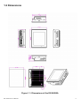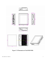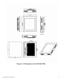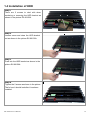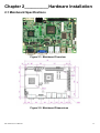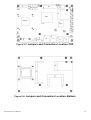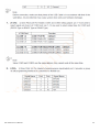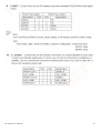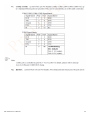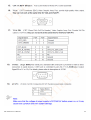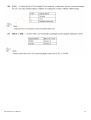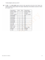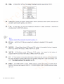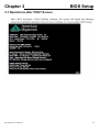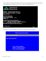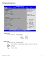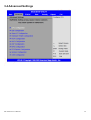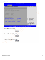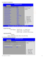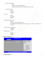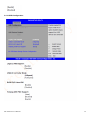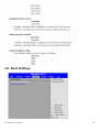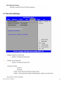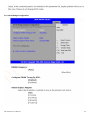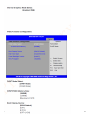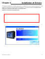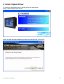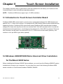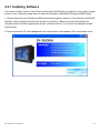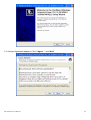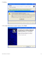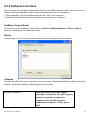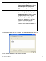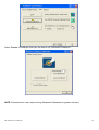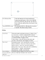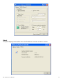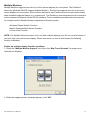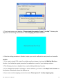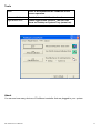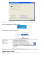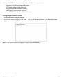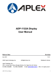
1
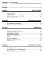
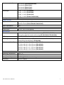
EX-96XX6A HMI
User Manual
Release Date
Revision
Nov 2011
®2011
EX-96XX6A User Manual
V1.0
All Rights Reserved.
Published in Taiwan
1
Warning!_______________________________
This equipment generates, uses and can radiate radio frequency energy and if not installed and
used in accordance with the instructions manual, it may cause interference to radio
communications.
It has been tested and found to comply with the limits for a Class A computing device pursuant to
FCC Rules, which are designed to provide reasonable protection against such interference when
operated in a commercial environment. Operation of this equipment in a residential area is likely
to cause interference in which case the user at his own expense will be required to take whatever
measures may be required to correct the interference.
Electric Shock Hazard – Do not operate the machine with its back cover removed. There are
dangerous high voltages inside.
EX-96XX6A User Manual
2
Packing List
Accessories (as ticked) included in this package are:
□ AC power cable
□ Driver & manual CD disc
□ Other.___________________(please specify)
Safety Precautions
Follow the messages below to avoid your systems from damage:
◆ Avoid your system from static electricity on all occasions.
◆ Prevent electric shock. Don‘t touch any components of this card when the card is
power-on. Always disconnect power when the system is not in use.
◆ Disconnect power when you change any hardware devices. For instance, when you
connect a jumper or install any cards, a surge of power may damage the electronic
components or the whole system.
EX-96XX6A User Manual
3
Table of Contents______________________
Warning!…………………………………………………………………………….……..….2
Disclaimer………………………………………………………………….…………………2
Chapter 1
Getting Started
1.1 Specifications………………………………………….………….……...…..6
1.2 Dimensions…………………………………...……………….…………......8
1.3 Brief Description of EX-96XX6A……..………………….………………13
1.4 Installation of HDD................................................................................14
Chapter 2
Hardware Installation
2.1 Mainboard Specifications………………………..…………….…………15
2.2 Jumpers Setting and Connectors………………………….……………18
Chapter 3
BIOS Setup
3.1 Operations after POST Screen.............................................................28
3.2 BIOS SETUP UTILITY................................................................30
3.3 System Overview.......................................................................31
3.4 Advanced Settings................................................................... 32
3.5 Advanced PCI/PnP Settings................................................................ 40
3.6 Boot Settings....................................................................................... 42
3.7 Security Settings.................................................................................. 44
3.8 Advanced Chipset Settings.................................................................. 45
3.9 Exit Options..........................................................................................49
Chapter 4
Installation of Drivers
4.1 Intel Chipset Driver.…………………………...……………………………52
4.2 Intel GMA 3150 VGA Chipset Driver..…....…......……………….......…..55
4.3 Intel 82574L Network adapter Driver……..................................……….58
4.4 Realtek HD Audio Driver Installation………………….…………………61
EX-96XX6A User Manual
4
Chapter 5
Touch Screen Installation
5.1 Introduction to Touch Screen Controller Board………………………....64
5.2 Windows 2000/XP USB Driver Installation………………….………..….64
Figures
Figure 1.1: Dimensions of the EX-96086A…..……………………………...8
Figure 1.2: Dimensions of EX-96126A…………….....……………………...9
Figure 1.3: Dimensions of EX-96156A..…………………...………………..10
Figure 1.4: Dimensions of EX-96176A..…………………...………………..11
Figure 1.5: Dimensions of the EX-96196A ……..…………………………...12
Figure 1.6: Front and Rear View of EX-96176A.........................................13
Figure 1.7: Rear View of EX-96126A and EX-96156A..............................13
Figure 2.1: Mainboard Overview……………………………………..……..…15
Figure 2.2: Mainboard Dimensions……………………………………………15
Figure 2.3: Jumpers and Connectors Location-TOP…………………...……16
Figure 2.4: Jumpers and Connectors Location- Bottom………………….…16
EX-96XX6A User Manual
5
Chapter 1________________Getting Started
1.1 Specifications
Model No.
Specs
EX-96086A
EX-96126A
EX-96156A
EX-96176A
EX-96196A
System
Processor
Intel Atom D525 1.8GHz processor FSB 800MHz
System Chipset
Intel ICH8M Chipset
System Memory
1 x 204 Pin SO-DIMM DDR3 800GHz, up to 2GB SDRAM
Storage
1 x 2 .5" SATA HDD Space
1 x CF Internal Slot (EX-96086A)
1 x CF External Slot for option (EX-96126A/96156A/96176A/96196A)
External I/O Port
EX-96086A
4 x USB ports
2 x LAN ports
1 x DB-15 VGA
1 x DB-9 RS-232
1 x DB-9 RS-422/485, default RS-485
1 x 2 Pin terminal block connector
EX-96126A/96156A/96176A/96196A
4 x USB ports
2 x LAN ports
1 x DB-15 VGA
2 x DB-9 RS-232
1 x DB-9 RS-422/485, default RS-485
1 x DC 3 Pin terminal block power input
1 x 8 Pin terminal block 2in/2out GPIO, power switch and VCC
1 x Audio Line-out 3.5mm jack
Expansion Slots
None
OS support
Windows CE 6.0, XP Pro, XP Embedded, Windows Embedded Standard 7
LCD
Display Type
Max. Resolution
8”
TFT-LCD
12.1”
TFT-LCD
15”
TFT-LCD
17”
TFT-LCD
19”
TFT-LCD
800x600 (EX-96086A/96126A)
1024x768 (EX-96156A)
1280x1024 (EX-96176A/96196A)
Max. Color
262K (EX-96086A/96126A)
16.2M (EX-96156A/EX-96196A)
16.7M (EX-96176A)
EX-96XX6A User Manual
6
Luminance (cd/m2)
350 (cd/m2) (EX-96086A/96126A)
400 (cd/m2) (EX-96156A)
550 (cd/m2) (EX-96176A)
350 (cd/m2) (EX-96196A)
View Angle
H:130° / V:110° (EX-96086A)
H:140° / V:110° (EX-96126A)
H:160° / V:140° (EX-96156A)
H:170° / V:160° (EX-96176A/96196A)
Backlight Lifetime
50,000 hrs
Touch Screen
Type
Overlay Resistive Touch (EX-96086A/96126A)
Resistive Touch (EX-96156A/96176A/96196A)
Light Transmission
80%
Power Supply
Power Input
DC 12V / DC 11~32V (option)
Mechanical
Construction
Plastic molding front panel and metal housing (EX-96086A/96126A)
Heavy-duty steel front panel and housing (EX-96156A/96176A/96196A)
IP Rating
Front Panel IP65
Mounting
Panel/VESA 75x75 Mount (EX-96086A/96126A/96156A/96176A)
Panel/VESA 100x100 Mount (EX-96196A)
Dimensions (WxHxD)
231 (W) x 176 (H) x 76.3 (D) mm (EX-96086A)
317 (W) x 243 (H) x 76.6 (D) mm (EX-96126A)
410 (W) x 310 (H) x 70.6 (D) mm (EX-96156A)
439 (W) x 348 (H) x 71.1 (D) mm (EX-96176A)
484 (W) x 400 (H) x 74.5 (D) mm (EX-96196A)
Environmental
Operating Temperature
0~50 ゚ C
Storage Temperature
-30~60 ゚ C
Storage Humidity
10~90% @40 ゚ C non-condensing
Certificate
CE/FCC Class A
EX-96XX6A User Manual
7
1.2 Dimensions
Figure 1.1: Dimensions of the EX-96086A
EX-96XX6A User Manual
8
Figure 1.2: Dimensions of the EX-96126A
EX-96XX6A User Manual
9
Figure 1.3: Dimensions of the EX-96156A
EX-96XX6A User Manual
10
Figure 1.4: Dimensions of the EX-96176A
EX-96XX6A User Manual
11
Figure 1.5: Dimensions of the EX-96196A
EX-96XX6A User Manual
12
1.3 Brief Description of the EX-96XX6A
The EX-96XX6A is a power-optimized and delivers robust performance-per-watt for embedded HMI.
The powered by an Atom D525 1.8 GHz processor and offer full sizes:8/12.1/15/17/19-inch. It comes
with a compact flash slot, 2.5-inch hard disk drive, DDR3 memory, audio jack (for
EX-96126A~96196A), 2 Ethernet, DC input, and 4 USB ports. The unit supports Windows CE6.0, XP
Pro, XP Embedded and Windows Embedded Standard 7. The fanless touch panel computer is ideal
for use as Web Browser, Terminal and HMI at all levels of automation control.
Figure 1.6: Front and Rear View of EX-96176A
Figure 1.7: Rear View of EX-96126A and EX-96156A
EX-96XX6A User Manual
13
1.4 Installation of HDD
Step 1
There are 2 screws to deal with when
enclosing or removing the HDD bracket as
shown in the picture EX-96156A.
Step 2
Loosen screw and draw the HDD bracket
out as shown in the picture EX-96156A.
Step 3
Push into the HDD bracket as shown in the
picture EX-96156A.
Step 4
Tighten the 2 screws as shown in the picture.
That’s how it should look after it has been
installed.
EX-96XX6A User Manual
14
Chapter 2__________Hardware Installation
2.1 Mainboard Specifications
Figure 2.1: Mainboard Overview
Figure 2.2: Mainboard Dimensions
EX-96XX6A User Manual
15
Figure 2.3: Jumpers and Connectors Location-TOP
Figure 2.4: Jumpers and Connectors Location- Bottom
EX-96XX6A User Manual
16
Mainboard Specifications
Board Size
165 x 115mm
CPU Support
Intel Atom D525 /1.8GHz (onboard)
Chipset
Intel ICH8M
Memory Support 1 x 204 Pin SO-DIMM, up to 2GB DDR3 800MHz FSB
Super I/O
Winbond W83627UHG
BIOS
AMIBIOS
Storage
3 x SATA Connector
1 x Compact Flash II Slot
Network
2 x RJ-45 1000Mbps LAN Intel 82574L
USB
4 x USB 2.0 stack port for external
2 x USB 2.0 Pin header for internal
Serial
1 x RS232 port, DB9 connector for external (COM1),
pin 9 w/5V/12V/Ring select
1 x RS232/422/485 select header for internal (COM3), default
RS232
4 x RS232 header for internal (COM2,COM4,COM5,COM6)
Digital I/O
8-bit digital I/O by Pin header
4-bit digital Input
4-bit digital Output
Battery
Support CR2477 Li battery by 2-pin header
Audio
Support Audio via Realtek ALC662 HD audio decoder
Support Line-in, Line-out, MIC by 2x5-pin header
Keyboard
/Mouse
1x PS2 keyboard/mouse by 1x6 box pin header
Expansion Bus
1x PC 104+ connector (PCI master 4, jumper for +3.3V & 5V
select)
2x mini-PCI-express slot (1x full size, 1x half-size )
Power
Management
DC12V input
Front I/O
by 2x5-pin header
Power on/off switch
Reset switch
Power LED status
HDD LED status
EX-96XX6A User Manual
1 x 2-pin power input connector
17
Buzzer
Watchdog Timer Software programmable 1 – 255 second by Super I/O
1 x COM Port (COM1)
4 x USB 2.0 Ports (stack)
External I/O port 2 x RJ45 GbE Port (10/100/1000Mbps)
1 x VGA Port
1 x VGA 2x8 Pin Header
Temperature
Operating: 0℃–60℃
Storage: -20℃–70℃
Humidity
5% - 95%, non-condensing, operating
Power
Consumption
12V /1.6A (Intel D525 processor with 2GB DDR3 DRAM)
12V /1.3A (Intel N455 processor with 2GB DDR3 DRAM)
EMI/EMS
Meet CE/FCC class A
2.2 Jumpers Setting and Connectors
EX-96XX6A User Manual
18
EX-96XX6A User Manual
19
EX-96XX6A User Manual
20
EX-96XX6A User Manual
21
EX-96XX6A User Manual
22
EX-96XX6A User Manual
23
EX-96XX6A User Manual
24
EX-96XX6A User Manual
25
EX-96XX6A User Manual
26
EX-96XX6A User Manual
27
Chapter 3
BIOS Setup
3.1 Operations after POST Screen
EX-96XX6A User Manual
28
EX-96XX6A User Manual
29
3.2 BIOS SETUP UTILITY
EX-96XX6A User Manual
30
3.3 System Overview
EX-96XX6A User Manual
31
3.4 Advanced Settings
EX-96XX6A User Manual
32
3.4.1 CPU Configuration
EX-96XX6A User Manual
33
3.4.2 IDE Configuration
EX-96XX6A User Manual
34
3.4.3 Super IO Configuration
3.4.4 Hardware Health Configuration
EX-96XX6A User Manual
35
3.4.5 ACPI Configuration
3.4.6 AHCI Configuration
EX-96XX6A User Manual
36
3.4.7 MPS Configuration
3.4.8 PCI Express Configuration
EX-96XX6A User Manual
37
3.4.9 Smbios Configuration
EX-96XX6A User Manual
38
3.4.10 USB Configuration
EX-96XX6A User Manual
39
3.5 Advanced PCI/PnP Settings
EX-96XX6A User Manual
40
EX-96XX6A User Manual
41
3.6 Boot Settings
EX-96XX6A User Manual
42
EX-96XX6A User Manual
43
3.7 Security Settings
EX-96XX6A User Manual
44
3.8 Advanced Chipset Settings
EX-96XX6A User Manual
45
3.8.1 North Bridge Configuration
EX-96XX6A User Manual
46
EX-96XX6A User Manual
47
3.8.2 South Bridge Configuration:
EX-96XX6A User Manual
48
3.9 Exit Options
EX-96XX6A User Manual
49
EX-96XX6A User Manual
50
Chapter 4
Installation of Drivers
This chapter describes the installation procedures for software and drivers under the windows XP. The
software and drivers are included with the motherboard. The contents include Intel chipset driver,
VGA driver, LAN driver, Audio driver, Touch Panel driver
Installation instructions are given below.
I
EX-96XX6A User Manual
51
4.1 Intel Chipset Driver
To install the Intel chipset driver, please follow the steps below.
Step 1: Select Chipset from the list
Follow the step-by-step installation process to install the LMS_SQL driver.
EX-96XX6A User Manual
52
EX-96XX6A User Manual
53
Click Finish, when the installation process is complete, the Setup Complete screen appears. See as
picture.
EX-96XX6A User Manual
54
4.2 Intel GMA 3150 VGA Chipset Driver
To install the VGA drivers, follow the steps below to proceed with the installation.
1. Click Intel GMA 3150 VGA Chipset Driver.
Follow the step-by-step installation process to install the Graphics Media Accelerator driver.
EX-96XX6A User Manual
55
EX-96XX6A User Manual
56
EX-96XX6A User Manual
57
Click FINISH; A Driver Installation Complete.
4.3 Intel 82574L Network adapter Driver
To install the Intel 82574L Network adapter Driver, please follow the steps below.
Select LAN from the list
EX-96XX6A User Manual
58
Follow the step-by-step installation process to install the LAN driver.
EX-96XX6A User Manual
59
EX-96XX6A User Manual
60
Click FINISH; A Driver Installation Complete.
4.4 Realtek HD Audio Driver Installation
To install the Realtek High Definition (HD) Audio driver, please follow the steps below.
Select Audio from the list
EX-96XX6A User Manual
61
Follow the step-by-step installation process to install the Realtek HD Audio driver.
EX-96XX6A User Manual
62
Click FINISH; A Driver Installation Complete.
EX-96XX6A User Manual
63
Chapter 5
Touch Screen Installation
This chapter describes how to install drivers and other software that will allow your PenMount 6000
Controller Board to work with different operating systems.
NOTE: PenMount USB drivers support up to 15 USB controllers.
5.1 Introduction to Touch Screen Controller Board
PenMount 6300 USB control board is a touch screen control board designed for USB interface and
specific for 4, 5, 8-wire touch screens. It is designed with USB interface features with multiple devices
supporting function. PenMount 6300 control board using PenMount 6000 controller that has been
designed for those who may like and all-in-one solution with 10-bit A/D converter built-in to make the
total printed circuit board denser, circuit diagram also designed for 12-bit ADC for optional. There are
two connectors on this board, one connector is for 4, 5, 8-wire touch screen cable (optional), and
another is for 4-pin USB A type cable (optional).
Figure 5.1: Bird’s Eye View of Control Board
5.2 Windows 2000/XP/2003/Vista Universal Driver Installation
for PenMount 6000 Series
Before installing the Windows 2000/XP driver software, you must have the Windows 2000/XP system
installed and running on your computer. You must also have one of the following PenMount 6000
series controller or control boards installed: PM6500, PM6300.
EX-96XX6A User Manual
64
5.2.1 Installing Software
If you have an older version of the PenMount Windows 2000/XP driver installed in your system, please
remove it first. Follow the steps below to install the PenMount DMC6000 Windows 2000/XP driver.
1. Please make sure your PenMount 6000 device had plugged in advance. If your device uses RS232
interface, please plugged in before the machine is turned on. When the system first detects the
controller board, a screen appears that shows “Unknown Device”. Do not use this hardware wizard.
Press Cancel.
2. Insert the product CD install setup.exe. the screen below would appear. Click touch panel driver
EX-96XX6A User Manual
65
3. A License Agreement appears. Click “I Agree…” and “Next”
EX-96XX6A User Manual
66
4. Ready to Install the Program. Click “Install”
EX-96XX6A User Manual
67
5. Installing
6. The “Install Shield Wizard Completed” appears. Click “Finish”.
EX-96XX6A User Manual
68
5.2.2 Software Functions
Upon rebooting, the computer automatically finds the new 6000 controller board. The touch screen is
connected but not calibrated. Follow the procedures below to carry out calibration.
1. After installation, click the PenMount Monitor icon “PM” in the menu bar.
2. When the PenMount Control Panel appears, select a device to “Calibrate.”
PenMount Control Panel
The functions of the PenMount Control Panel are Device, Multiple Monitors, Tools and About,
which are explained in the following sections.
Device
In this window, you can find out that how many devices are detected on your system.
Calibrate
This function offers two ways to calibrate your touch screen. ‘Standard Calibration’ adjusts most touch
screens. ‘Advanced Calibration’ adjusts aging touch screens.
Standard Calibration
Click this button and arrows appear
pointing to red squares. Use your finger or
stylus to touch the red squares in
sequence. After the fifth red point
calibration is complete. To skip, press
‘ESC’.
EX-96XX6A User Manual
69
Advanced Calibration
Advanced Calibration uses 4, 9, 16 or 25
points to effectively calibrate touch panel
linearity of aged touch screens. Click this
button and touch the red squares in
sequence with a stylus. To skip, press
ESC’.
Command Calibration
Command call calibration function. Use
command mode call calibration function,
this can uses Standard, 4, 9, 16 or 25
points to calibrate E.g. Please run ms-dos
prompt or command prompt c:\Program
Files\PenMount Universa Driver\Dmcctrl.exe
-calibration 0 ( Standard Calibration)
Dmcctrl.exe - calibration ($) 0= Standard
Calibration 4=Advanced Calibration 4
9=Advanced Calibration 9 16=Advanced
Calibration 16 25=Advanced Calibration 25
1. Please select a device then click “Configure”. You can also double click the device too.
2.Click “Standard Calibration” to start calibration procedure
EX-96XX6A User Manual
70
NOTE: The older the touch screen, the more Advanced Mode calibration points you need for an
accurate calibration. Use a stylus during Advanced Calibration for greater accuracy. Please follow the
step as below:
3.Come back to “PenMount Control Panel” and select “Tools” then Click “Advanced
Calibration”.
EX-96XX6A User Manual
71
Select “Device” to calibrate, then you can start to do “Advanced Calibration”.
NOTE: Recommend to use a stylus during Advanced Calibration for greater accuracy.
EX-96XX6A User Manual
72
Setting
EX-96XX6A User Manual
73
About
This panel displays information about the PenMount controller and driver version.
EX-96XX6A User Manual
74
Multiple Monitors
Multiple Monitors supports from two to six touch screen displays for one system. The PenMount
drivers for Windows 2000/XP support Multiple Monitors. This function supports from two to six touch
screen displays for one system. Each monitor requires its own PenMount touch screen control board,
either installed inside the display or in a central unit. The PenMount control boards must be connected
to the computer COM ports via the RS-232 interface. Driver installation procedures are the same as
for a single monitor. Multiple Monitors supports the following modes:
Windows Extend Monitor Function
Matrox DualHead Multi-Screen Function
nVidia nView Function
NOTE: The Multiple Monitors function is for use with multiple displays only. Do not use this function if
you have only one touch screen display. Please note once you turn on this function the Rotating
function is disabled.
Enable the multiple display function as follows:
1. Check the “Multiple Monitor Support” box; then click “Map Touch Screens” to assign touch
controllers to displays.
2. When the mapping screen message appears, click “OK”
EX-96XX6A User Manual
75
3. Touch each screen as it displays “Please touch this monitor. Press ‘S’ to skip” Following this
sequence and touching each screen is called mapping the touch screens.
4. After the setting procedure is finished, maybe you need to calibrate for each panel and controller
NOTES:
1. If you used a single VGA output for multiple monitors, please do not use the Multiple Monitors
function. Just follow the regular procedure for calibration on each of your desktop monitors.
2. The Rotating function is disabled if you use the Multiple Monitors function.
3. If you change the resolution of display or screen address, you have to redo Map Touch Screens so
the system understands where the displays are.
4. If you more monitor mapping one touch screen, Please press ‘S’ to skip mapping step.
EX-96XX6A User Manual
76
Tools
Draw
Tests or demonstrates the PenMount touch
screen operation.
Advanced Calibration
Enable Advanced Calibration function
Right Button Icon
Enable right button function. The icon can
show on Desktop or System Tray (menu bar).
About
You can see how many devices of PenMount controller that are plugged to your system
EX-96XX6A User Manual
77
PenMount Monitor Menu Icon
The PenMount monitor icon (PM) appears in the menu bar of Windows 2000/XP system when you
turn on PenMount Monitor in PenMount Utilities.
PenMount Monitor has the following function
PenMount Rotating Functions
The PenMount driver for Windows 2000/XP supports several display rotating software packages.
EX-96XX6A User Manual
78
Windows Me/2000/XP support display rotating software packages such as:
• Portrait’s Pivot Screen Rotation Software
• ATI Display Driver Rotate Function
• nVidia Display Driver Rotate Function
• SMI Display Driver Rotate Function
• Intel 845G/GE Display Driver Rotate Function
Configuring the Rotate Function
1. Install the rotation software package.
2. Choose the rotate function (0°, 90°, 180°, 270°) in the 3rd party software. The calibration screen
appears automatically. Touch this point and rotation is mapped.
NOTE: The Rotate function is disabled if you use Monitor Mapping
EX-96XX6A User Manual
79