1
Stratos®Pro A2... CC
User Manual
Latest Product Information:
www.knick.de
Warranty
Warranty
Defects occurring within 3 years from delivery date shall be remedied
free of charge at our plant (carriage and insurance paid by sender).
Sensors, fittings, and accessories: 1 year.
Subject to change without notice.
Return of products under warranty
Please contact our Service Team before returning a defective device.
Ship the cleaned device to the address you have been given.
If the device has been in contact with process fluids, it must be
decontaminated/disinfected before shipment. In that case, please
attach a corresponding certificate, for the health and safety of our
service personnel.
Disposal
Please observe the applicable local or national regulations concerning
the disposal of “waste electrical and electronic equipment”.
2
Documents Supplied
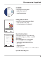
CD-ROM
Complete documentation:
• Instruction manuals
• Safety instructions
• Short instructions
Stratos® Pro Series
Safety Instructions
Safety Information
In official EU languages and others.
• ATEX / IECEX / FM / CSA
• EC Declarations of Conformity
www.knick.de
Stratos® Pro
A211 / A411
Short Instructions.........................3
Kurzübersicht .............................. 15
QuickStart .................................... 27
Быстрый старт........................... 39
Inicio rápido ................................ 51
Início rápido ................................ 63
Guida rapida................................ 75
Snabbstart.................................... 87
QuickStart .................................... 99
Other languages: www.knick.de
Short Instructions
In German, English, French, Russian,
Spanish, Portuguese, Italian, Swedish
and Dutch.
More languages on CD-ROM and
on our website: www.knick.de
• Installation and commissioning
• Operation
• Menu structure
• Calibration
• Error messages and recommended actions
Specific Test Report
3
Contents
Documents Supplied...................................................................... 3
Introduction..................................................................................... 7
Intended Use.......................................................................................... 7
Safety Information.......................................................................... 8
Overview of Stratos Pro A2... CC................................................... 9
Assembly.........................................................................................10
Package Contents...............................................................................10
Mounting Plan, Dimensions...........................................................11
Pipe Mounting, Protective Hood...................................................12
Panel Mounting...................................................................................13
Installation......................................................................................14
Installation Instructions....................................................................14
Rating Plates / Terminal Assignments.........................................15
Wiring of Stratos Pro A201/A211 CC............................................16
Wiring Examples..................................................................................17
User Interface, Keypad.................................................................20
Display.............................................................................................21
Signal Colors (Display Backlighting)............................................21
Measuring Mode...........................................................................22
Selecting the Mode / Entering Values.......................................23
Operating Modes...........................................................................26
Menu Structure of Modes and Functions..................................27
HOLD Mode..........................................................................................28
Alarm.......................................................................................................29
Alarm and HOLD Messages.............................................................30
Overview of Configuration..........................................................31
Setup and Channel Selection on the Device...........................32
Sensors A and B – Arrangement.................................................32
Channel Selection and Display Assignment............................32
4
Contents
Calculations (CALC).......................................................................33
Configuration (Original for Copy)..............................................40
Configuring Sensors A, B..................................................................42
Current Output 1.................................................................................46
Current Output 2.................................................................................54
CONTROL input...................................................................................56
Alarm Settings......................................................................................58
Time and Date......................................................................................60
Tag Number .................................................................................................60
Calibration......................................................................................62
Calibration by Input of Cell Factor................................................63
Measurement.................................................................................64
Diagnostics.....................................................................................65
Service.............................................................................................70
Operating States............................................................................73
Product Line and Accessories.....................................................75
Specifications.................................................................................76
Error Handling................................................................................80
Error Messages...............................................................................81
Sensoface........................................................................................83
FDA 21 CFR Part 11.......................................................................85
Electronic Signature – Passcodes..................................................85
Audit Trail...............................................................................................85
Index................................................................................................86
Trademarks............................................................................................91
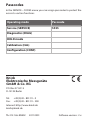
Passcodes........................................................................................92
5
Contents
6
Introduction
Intended Use
Stratos Pro A2... CC is a 2-wire device for two-channel measurement
of electrical conductivity and temperature in liquids. The device has
been designed for measurements before and after cation exchangers
using commercial 2- and 4-electrode sensors. Different parameters
can be calculated from the two conductivity values, e.g. difference,
ratio, rejection, but also the pH value of feed water.
The sturdy molded enclosure can be fixed into a control panel or
mounted on a wall or at a post. The protective hood, which is available as accessory, provides additional protection against direct
weather exposure and mechanical damage.
Plain-text messages in a large, backlit display allow intuitive operation. The colored display backlighting signals alarm messages (red) or
HOLD mode (orange).
The “Sensocheck“ automatic monitoring of sensor and cables and
the “Sensoface“ function for clear indication of the sensor condition
provide excellent diagnostics.
The internal logbook (TAN SW-A002) can handle up to 100 entries –
up to 200 with AuditTrail (TAN SW-A003).
Password protection for granting access rights during operation can
be configured.
The floating, digital control input “HOLD“ allows remote controlled
switching to HOLD mode.
The “CONTROL“ input allows evaluation of external monitoring equipment, such as a flow monitoring system. For that purpose, you can
also monitor the current input (optional) for keeping a desired value.
The device provides two current outputs (for transmission of
measured value and temperature, for example).
7
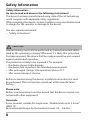
Safety Information
Safety information –
Be sure to read and observe the following instructions!
The device has been manufactured using state of the art technology
and it complies with applicable safety regulations.
When operating the device, certain conditions may nevertheless lead
to danger for the operator or damage to the device.
See also separate document:
• “Safety Instructions“
CAUTION!
Commissioning must only be performed by trained personnel authorized by the operating company! Whenever it is likely that protection
has been impaired, the device shall be made inoperative and secured
against unintended operation.
The protection is likely to be impaired if, for example:
• the device shows visible damage
• the device fails to perform the intended measurements
• after prolonged storage at temperatures above 70°C
• after severe transport stresses
Before recommissioning the device, a professional routine test must
be performed. This test must be carried out at the manufacturer's
factory.
Please note:
Before commissioning it must be proved that the device may be connected with other equipment.
Terminals:
2
Screw terminal, suitable for single wires / flexible leads up to 2.5 mm
(AWG 14).
Recommended torque for the terminal screws: 0,5 ... 0.6 Nm.
8
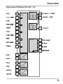
Overview
Overview of Stratos Pro A2... CC
A
CC
input
Output 1
B
8
9
C
Output 2
D
E
17
F
G
H
RS 485
I
1
2
K
3
4
5
6
10
11
13
14
Current
input
HOLD
input
Control
input
9
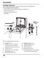
Assembly
Package Contents
Check the shipment for transport damage and completeness!
The package should contain:
• Front unit, rear unit, bag containing small parts
• Specific test report
• Documentation (cf Pg 3)
• CD-ROM
1
11
10
2
3
9
8
7 6
5
4
Fig.: Assembling the enclosure
1) Jumper (3 x)
2) Washer (1 x), for conduit
mounting: Place washer
between enclosure and nut
3) Cable tie (3 x)
4) Hinge pin (1 x), insertable
from either side
5) Enclosure screw (4 x)
10
6) Sealing insert (1 x)
7) Rubber reducer (1 x)
8) Cable gland (3 x)
9) Filler plug (3 x)
10) Hexagon nut (5 x)
11) Sealing plug (2 x), for sealing
in case of wall mounting
Assembly
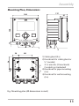
Mounting Plan, Dimensions
117
41
14
148
148
42
6.2
74
34
42
42
1
21
43
2
80
1)Cable gland (3 x)
2)Knockouts for cable gland or
½" conduit,
21.5 mm dia. (2 knockouts)
3
Conduits not included!
3)Knockout for pipe mounting
4
(4 x)
4)Knockout for wall mounting
(2 x)
Fig.: Mounting plan (All dimensions in mm!)
11
Assembly
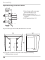
Pipe Mounting, Protective Hood
ø40...ø60
1
2
3
1)Hose clamp with worm gear
drive to DIN 3017 (2 x)
2)Pipe-mount plate (1 x)
3)For vertical or horizontal posts
or pipes
4)Self-tapping screw (4 x)
4
Fig.: ZU 0274 pipe-mount kit (All dimensions in mm!)
147
91
185
199
Fig.: ZU 0737 protective hood for wall and pipe mounting
(All dimensions in mm!)
12
Assembly
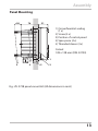
Panel Mounting
<30
76
31
1)Circumferential sealing
(1 x)
2)Screw (4 x)
3)Position of control panel
4)Span piece (4 x)
5)Threaded sleeve (4 x)
Cutout
138 x 138 mm (DIN 43700)
1
1...22
5
4
3
2
Fig.: ZU 0738 panel-mount kit (All dimensions in mm!)
13
Installation
Installation Instructions
• Installation of the device must be carried out by trained experts in
accordance with this instruction manual and as per applicable local
and national codes.
• Be sure to observe the technical specifications and input ratings
during installation!
• Be sure not to notch the conductor when stripping the insulation!
• The supplied current must be galvanically isolated. If not, connect
an isolator module.
• All parameters must be set by a system administrator prior to
commissioning!
Terminals:
suitable for single wires / flexible leads up to 2.5 mm2 (AWG 14)
14
Installation
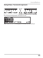
Rating Plates / Terminal Assignments
Fig.: Terminal assignments of Stratos Pro A2...
Fig.: Stratos Pro A2...N rating plate at outside bottom of front
15
Installation
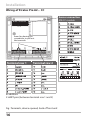
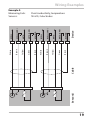
Wiring of Stratos Pro A2... CC
Sensor connection
MK-CC module
Areas for placing the
screwdriver to pull out
the terminals
1
9
Terminal row 1
10
18
HART
Terminal row 2
In addition:
2 HART pins (between terminal row 1 and 2)
Fig.: Terminals, device opened, back of front unit
16
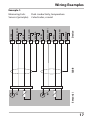
Wiring Examples
Example 1:
H
K
Device
I
A
B
Sensor(s)
Cable
G
B SHIELD
F
B RTD
E
B RTD (GND)
D
B CELL (GND)
C
B CELL
A RTD
B
A SHIELD
A CELL (GND)
A
A RTD (GND)
A CELL
Measuring task:
Dual conductivity, temperature
Sensors (principle): 2 electrodes, coaxial
17
18
A
Cable
B SHIELD
K
Device
B RTD (GND)
B RTD
I
Sensor(s)
B
H
Black
G
Green
F
Yellow / Red
B CELL
E
B CELL (GND)
A SHIELD
D
Brown / Gray
C
White / Pink
A RTD
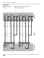
Example 2:
Measuring task:
Sensors:
Black
A CELL (GND)
B
A RTD (GND)
A CELL
A
Green
Yellow / Red
Brown / Gray
White / Pink
Wiring Examples
Dual conductivity, temperature
SE 604, 2 electrodes
A
Cable
B SHIELD
K
Device
B RTD (GND)
B RTD
I
Sensor(s)
B
H
Black
G
Green
F
Yellow
B CELL
E
B CELL (GND)
A SHIELD
D
Brown
C
White
A RTD
Example 3:
Measuring task:
Sensors:
Black
A CELL (GND)
B
A RTD (GND)
A CELL
A
Green
Yellow
Brown
White
Wiring Examples
Dual conductivity, temperature
SE 610, 2 electrodes
19
User Interface, Keypad
1
MEMO
SENS
2
3
4
Key
Function
meas
•
•
•
•
•
•
info
enter
•
menu
Arrow keys
up / down
Arrow keys
left / right
20
•
•
•
•
•
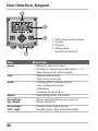
1 IrDA transmitter/receiver
2 Display
3 Keypad
4 Rating plate
(enclosure bottom)
Return to last menu level
Directly to measuring mode (press > 2 s)
Measuring mode: other display
Retrieve information
Show error messages
Configuration: Confirm entries,
next configuration step
Calibration:
Continue program flow
Measuring mode: Call menu
Menu: Increase/decrease a numeral
Menu: Selection
Previous/next menu group
Number entry: Move between digits
Display
1
2
3
4
5
6
7
8
9
10
11
MEMO
SENS
23
12
13
14
24
15
16
22
21
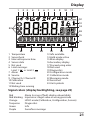
1 Temperature
2 Sensocheck
3 Interval/response time
4 Sensor data
5 Not used
6 Limit message:
Limit 1
or Limit 2
7 Alarm
8 Service
9 Channel A / Channel B
10Calibration
11Not used
12Waiting time running
20
19
18
17
13Info available
14Hold mode active
15Main display
16Secondary display
17Proceed using enter
18Not used
19Diagnostics
20Configuration mode
21Calibration mode
22Measuring mode
23Sensoface
24Unit symbols
Signal colors (display backlighting, see page 25)
Red
Red blinking
Orange
Turquoise
Green
Purple
Alarm (in case of fault: display values blink)
Input error: illegal value or wrong passcode
HOLD mode (Calibration, Configuration, Service)
Diagnostics
Info
Sensoface message
21
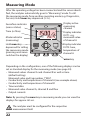
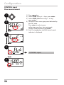
Measuring Mode
After the operating voltage has been connected and the sensor identified, the analyzer automatically goes to “Measuring“ mode. To call
the measuring mode from another operating mode (e.g. Diagnostics,
Service): Hold meas key depressed (> 2 s).
Sensoface indicator
(sensor status)
Time (or flow)
Mode indicator
(measuring)
Hold meas key
depressed for calling
the measuring mode
(pressing once more
switches the display)
Display active
measuring
channel
Display indicates
OUT1: e.g.
measured value
of channel A
Display indicates
OUT2: here,
temperature of
channel A
enter key
Depending on the configuration, one of the following displays can be
set as standard display for the measuring mode (see page 24):
• Measured values channel A and channel B as well as time
(default setting)
Measured value and tag number ("TAG")
• Conductivity and temperature of channel A (see example above)
• Conductivity and temperature of channel B
• Time and date
• Measured value channel A, channel B and flow
• Output currents
Note: By pressing the meas key in measuring mode you can view the
displays for approx. 60 sec.
The analyzer must be configured for the respective
measurement task!
22
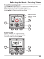
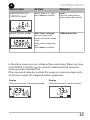
Selecting the Mode / Entering Values
To select the operating mode:
1)Hold meas key depressed (> 2 s) (directly to measuring mode)
2)Press menu key: the selection menu appears
3)Select operating mode using left / right arrow key
4)Press enter to confirm the selected mode
Selection menu
Selected mode
(blinks)
4
1
3
2
To enter a value:
5)Select numeral: left / right arrow key
6)Change numeral: up / down arrow key
7)Confirm entry by pressing enter
5
7
6
23
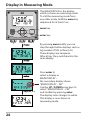
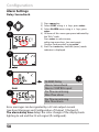
Display in Measuring Mode
The MAIN DISPLAY is the display
which is shown in measuring mode.
To call the measuring mode from
any other mode, hold the meas key
depressed for at least 2 sec.
meas key
enter key
By pressing meas briefly you can
step through further displays such as
tag number (TAG) or flow (L/h).
These displays are turquoise.
After 60 sec they switch back to the
main display.
approx. 2 s
24
Press enter to
select a display as
MAIN DISPLAY –
the secondary display shows
"MAIN DISPLAY – NO“.
Use the UP / DOWN arrow keys to
select "MAIN DISPLAY – YES“
and confirm by pressing enter.
The display color changes to white.
This display is now shown in
measuring mode.
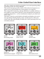
Color-Coded User Interface
The color-coded user interface guarantees increased operating safety.
Operating modes are clearly signaled.
The normal measuring mode is white. Information text appears on a
green screen and the diagnostic menu appears on turquoise.
The orange HOLD mode (e.g. during calibration) is quickly visible as is
the magenta screen which indicates asset management messages for
predictive diagnostics – such as maintenance request, pre-alarm and
sensor wear.
The alarm status has a particularly noticeable red display color and is
also signaled by flashing display values. Invalid inputs or false passcodes cause the entire display to blink red so that operating errors are
noticeably reduced.
White:
Measuring mode
Red blinking:
Alarm, errors
Turquoise:
Magenta:
Maintenance request Diagnostics
Orange:
HOLD mode
Green:
Information texts
25
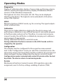
Operating Modes
Diagnostics
Display of calibration data, display of sensor data, performing a d
evice
self-test, viewing the logbook entries, display of hardware/software
versions of the individual components.
The logbook can store 100 events (00...99). They can be displayed
directly on the device. The logbook can be extended to 200 entries
using a TAN (Option).
HOLD
Manual activation of HOLD mode, e.g. for servicing. The signal outputs
adopt a defined state.
Calibration
There are no stable calibration solutions for the µS/cm range, and
performing a calibration is very difficult because it only works properly
in the flow under exclusion of air. Therefore, it is easier and more precise just to enter the cell factor or calibrate by carrying out a reference
measurement, if appropriate.
During calibration the device is in HOLD mode.
During calibration the deviceremains in the HOLD mode until it is
stopped by the operator.
Configuration
The analyzer must be configured for the respective measurement
task. In the “Configuration“ mode you select the connected sensor, the
measuring range to be transmitted, and the conditions for warning and
alarm messages. During configuration the device is in HOLD mode.
Configuration mode is automatically exited 20 minutes after the last
keystroke. The device returns to measuring mode.
Service
Maintenance functions (current source), IrDA operation, passcode
assignment, reset to factory settings, enabling of options (TAN).
26
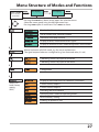
Menu Structure of Modes and Functions
Meas. mode
(main display
selectable)
TAG display
CLK display
after 60 s
after 60 s
Pressing the menu key (down arrow) opens the selection menu.
Select the menu group using the left/right arrow keys.
Pressing enter opens a menu item. Press meas to return.
Display of calibration data
Self test: RAM, ROM, EEPROM, module
100 events with date and time
Display of direct, uncorrected sensor signals
Display of software version, model designation, serial number
Manual activation of HOLD mode, e.g. for sensor replacement.
The signal outputs behave as configured (e.g. last measured value, 21 mA)
Calibrating sensor A by input of cell factor
Calibrating sensor B by input of cell factor
Configuration
Display of measured values for validation (simulators)
(Access via
code, factory
setting:
5555)
Current source, output 1
Current source, output 2
Activating the IrDA interface
Specifying access codes for operating modes
Reset to factory setting
Enabling an option via TAN
27
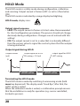
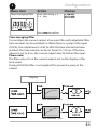
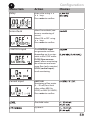
HOLD Mode
The HOLD mode is a safety mode during configuration, calibration,
and servicing. Output current is frozen (LAST) or set to a fixed value
(FIX).
The HOLD mode is indicated by orange display backlighting.
HOLD mode, display icon:
Output signal response
• LAST: The output current is frozen at its last value. Recommended
for short configuration procedures. The process should not change
decisively during configuration. Changes are not noticed with this
setting!
• FIX: The output current is set to a value that is noticeably different
from the process value to signal the control system that the analyzer
is being worked at.
Output signal during HOLD:
Output current
[mA]
Output signal for HOLD
FIX setting = 21.0 mA
Output signal for HOLD
LAST setting
21
4
HOLD active
HOLD active
Terminating the HOLD mode
The HOLD mode is ended by switching to measuring mode (hold
meas key depressed). The display reads “Good Bye“, after that, the
HOLD mode is exited.
When the calibration mode is exited, a confirmation prompt ensures
that the installation is ready for operation (e.g.: sensor reinstalled,
located in process).
28
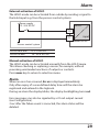
Alarm
External activation of HOLD
The HOLD mode can be activated from outside by sending a signal to
the Hold input (e.g. from the process control system).
Power supply
12...24 V AC/DC
HOLD
10
11
input
Stratos Pro A2...
Process control system
HOLD inactive
HOLD active
0...2 V AC/DC
10...30 V AC/DC
Manual activation of HOLD
The HOLD mode can be activated manually from the HOLD menu.
This allows checking or replacing a sensor, for example, without
provoking unintended reactions of outputs or contacts.
Press meas key to return to selection menu.
Alarm
When an error has occurred, Err xx is displayed immediately.
Only after expiry of a user-defined delay time will the alarm be
registered and entered in the logbook.
During an alarm the display blinks, the display backlighting turns red.
Error messages can also be signaled by a 22 mA output current
(see Configuration).
2 sec after the failure event is corrected, the alarm status will be
deleted.
29
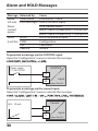
Alarm and HOLD Messages
Message Released by
Alarm
Sensocheck
(22 mA) Error messages
Alarm
contact
opens
HOLD
HOLD
(Last/Fix) CONF
CAL
SERVICE
Cause
Polarization / Cable
Flow (CONTROL input)
Flow (current input)
ERR A / ERR B: conductance > 250,000 µS
ERR A / ERR B: conductivity > 1,000 µS/cm
HOLD via menu or input
Configuration
Calibration
Service
To generate a message via the CONTROL input:
Open the “Configuration“ menu to activate the message:
CONTROL
Power supply
12...24 V AC/DC
13
14
input
Stratos Pro A2...
To generate a message via the current input:
Open the “Configuration“ menu to activate the message:
Current
0(4) ... 20 mA:
5
6
30
input
Stratos Pro A2...
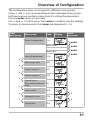
Overview of Configuration
The configuration steps are assigned to different menu groups.
Using and you can jump between the individual menu groups.
Each menu group contains menu items for setting the parameters.
Pressing enter opens a menu item.
Use and to edit a value. Press enter to confirm/save the settings.
To return to measurement: Hold meas key depressed (> 2 s).
Display
Select
menu item
Menu group
Code
Sensor A parameters
S_A:
enter
Menu item 1
enter
...
Select
menu group
enter
Menu item ...
Sensor B parameters
S_B:
Measuring mode
MES:
Current output 1
OT1:
Current output 2
OT2:
enter
Control input
(flow measurement or IN:
level)
Alarm mode
ALA:
Setting the clock
CLK:
Tag number
TAG:
31
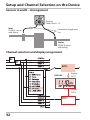
Setup and Channel Selection on the Device
Sensors A and B – Arrangement
Analyzer
Stratos Pro A... CC
Inlet:
COND A sensor
with fitting
Connection length max.
3m
Outlet:
COND B sensor
with fitting
Channel selection and display assignment
DISPLAY:
Display
OUT 1
Display
OUT 2
32
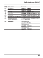
Calculations (CALC)
Calculation
Difference
Ratio
Passage
Rejection
Deviation
pH value acc. to VBG 450
Variable pH value,
factors specifiable
Formula
11+log((COND A – COND B /3)/243)
11+log((COND A – COND B /F1)/F2)
F1, F2 specifiable
PARAMETER W
PARAMETER A
PARAMETER B
33
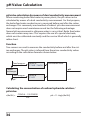
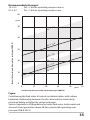
pH Value Calculation
pH value calculation by means of dual conductivity measurement
When monitoring boiler feed water in power plants, the pH value can be
calculated by means of a dual conductivity measurement. For that purpose,
the boiler feed water conductance is measured before and after the cation
exchanger. This commonly used method of indirect pH value measurement
does not require much maintenance and has the following advantage:
Normal pH measurement in ultrapure water is very critical. Boiler feed water
does not contain many ions. This requires the use of a special electrode,
which must be calibrated constantly and the service life of which is generally
rather short.
Function
Two sensors are used to measure the conductivity before and after the cation exchanger. The pH value is inferred from these two conductivity values
according to the calculation formulas shown below:
Cond measuring point A
Sensor A
TC: NH3 / NaOH
Cation
exchanger
Calculation Block
pH
Cond measuring point B
Sensor B
TC: HCl
H2O
Calculating the concentration of sodium hydroxide solution /
pH value:
c(NaOH) =
34
COND A – 1/3 COND B
243
pH = 11+log[c(NaOH)]
Recommended pH ranges:
10 ± 0.2 9.5 ± 0.2 for < 136 bars operating overpressure or
for > 136 bars operating overpressure
60
µS/cm
50
10.2
pH =
Conductivity measured before cation exchanger (COND A)
40
10.0
pH =
30
pH =
20
10
9.8
pH =
9.7
pH =
9.5
pH =
9.3
0
0
10
20
30
40
50
µS/cm
Conductivity measured after cation exchanger (COND B)
Figure:
Conditioning the feed water of natural circulation boilers with sodium
hydroxide. Relationship between the pH value and the conductivity
measured before and after the cation exchanger.
Source: Appendix to VGB guideline for boiler feed water, boiler water and
steam of steam generators above 68 bars permissible operating over
pressure (VGB-R 450 L)
35
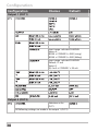
Configuration
Configuration
Choices
(this setting applies to both
channels, A and B)
(Selected in text line)
36
Default
Configuration
1)The cell factor can be modified by an entry in the configuration
menu or by calibration (one storage position). This means, a cell factor determined by calibration is taken over by pressing enter during
configuration. It remains unchanged until a new value is entered.
2)For conductivity (μS/cm), the range selection determines the max.
resolution. If the selected range is exceeded, the device automatically switches to the next higher range until the max. measurement
limit is reached (9999 μS/cm).
This applies to display values and current outputs. The current outputs are adjusted using a floating-point editor which allows settings
over several decades. The initial range of the editor is the selected
range:
Selected
resolution
Displayed range (or floating-point editor)
37
Configuration
Configuration
Choices
Default
Output 1 (OUT1)
Input range: selected CHANNEL
Vertex X :
BEGIN ≤ CORNER X ≤ END (rising)
BEGIN ≥ CORNER X ≥ END (falling)
Input range: selected CHANNEL
Default: 12 mA
Vertex Y:
(0) 4 mA ≤ CORNER Y ≤ 20 mA
Output 2 (OUT2)
Selection as for
OUT1
All following settings are made as for output 1 (OUT1)
38
Configuration
Control input (CNTR_IN)
12000
pulses/liter
0 ... 20000
pulses/liter
Alarm (ALARM)
These menu items appear only if selected.
LIMIT I-IN can be used to measure and monitor the current input (e.g. flow).
For monitoring, you can enter a setpoint at which an alarm message is released:
"ERR 71 LIMIT I-INPUT“ (22 mA).
***) Hysteresis fixed at 5% of threshold value
*)
**)
Configuration
Choices
Default
Switching clock
outputs
(Rel1/Rel2)
Real-time
(CLOCK)
Tag number (TAG)
(Input in text line,
max. 32 digits)
___
39
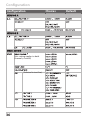
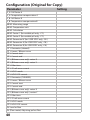
Configuration (Original for Copy)
Parameter
S_A: Cell factor A
S_A: Temperature compensation A
S_B: Cell factor B
S_B: Temperature compensation B
MEAS: Measuring range
MEAS: Temperature unit
MEAS: Calculation
MEAS: Factor 1 (for variable pH only, -C7-)
MEAS: Factor 2 (for variable pH only, -C7-)
MEAS: Parameter W (for USER SPEC only, -C8-)
MEAS: Parameter A (for USER SPEC only, -C8-)
MEAS: Parameter B (for USER SPEC only, -C8-)
OT1: Parameter (channel)
OT1: Linear / Bilinear curve
OT1: Current start
OT1: Current end
OT1: (Bilinear curve only) vertex X
OT1: (Bilinear curve only) vertex Y
OT1: Filter time
OT1: 22 mA error current
OT1: HOLD mode
OT1: HOLD-FIX current
OT2: Parameter (CHANNEL)
OT2: Linear / Bilinear curve
OT2: Current start
OT2: Current end
OT2: (Bilinear curve only) vertex X
OT2: (Bilinear curve only ) vertex Y
OT2: Filter time
OT2: 22 mA error current
OT2: HOLD mode
OT2: HOLD-FIX current
IN: Level or flow
IN: (Flow meter) Adjusting pulses/liter
40
Setting
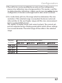
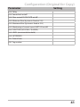
Configuration (Original for Copy)
Parameter
Setting
ALA: Delay
ALA: Sensocheck on/off
ALA: Flow control FLOW CNTR on/off
ALA: Minimum flow (hysteresis fixed at 5 %)
ALA: Maximum flow (hysteresis fixed at 5 %)
ALA: Monitoring of current input LIMIT I-IN on/off
ALA: FUNCTION (LO LEVEL / Hi LEVEL)
ALA: LEVEL (monitored threshold)
ALA: HYSTERESIS
CLK: Time & Date
TAG: Tag number
41
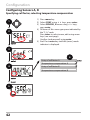
Configuration
Configuring Sensors A, B
Specifying cell factor, selecting temperature compensation
1
2
1) Press menu key.
2) Select CONF using keys, press enter.
3) Select SENSOR_A menu using keys,
press enter.
4) All items of this menu group are indicated by
the “S_A:” code.
Press enter to select menu, edit using arrow
keys (see next page).
Confirm (and proceed) using enter.
5) End: Press meas key until the [meas] mode
indicator is displayed.
3
4
Entry of cell factor A
4
Temperature compensation A
Entry of cell factor B
Temperature compensation B
5
42
Configuration
4
Menu item
Action
Sensor A
Select SENSOR_A menu
using keys,
press enter.
Enter cell factor
Sensor A
Modify digit using
keys,
select next digit using
keys.
Choices
Press enter to confirm.
Temp compensation
selection
Select using keys.
Press enter to confirm.
OFF
LIN*
NLF
NaCl
HCl
NH3
NaOH
* With LIN selected:
Enter temperature
coefficient
00.00 %/K ... +19.99 %/K
Sensor B
Select SENSOR_B menu
using keys,
press enter.
Enter cell factor
Sensor B...
Configuration as for
sensor A
43
Configuration
Measuring Range, Calculation of Output Parameters
1
2
1) Press menu key.
2) Select CONF using keys, press enter.
3) Select MEAS MODE menu using keys,
press enter.
4) All items of this menu group are indicated by
the “MES:” code.
Press enter to select menu,
edit using arrow keys (see next page).
Confirm (and proceed) using enter.
5) End: Press meas key until the [meas] mode
indicator is displayed.
3
4
Range (resolution)
4
Temperature unit
Calculations
Parameter
(for -C7- variable pH or -C8-)
5
44
Configuration
4
Menu item
Action
Range (resolution)
Select using keys.
Press enter to confirm.
Temperature unit
Select °C or °F using
keys.
Choices
Press enter to confirm.
Calculation
Select using keys.
Press enter to confirm.
Calculation type
Select desired calculation
type using keys:
Press enter to confirm.
With
-C7- variable pH
or
-C8- USER SPEC
selected, you are requested to enter parameters.
-C7- Factor 1: 03.00
(01.00 ... 10.00)
-C7- Factor 2: 0243
(0100 ... 0500)
-C8- Parameter W:
(xxxx E-3 1000 E-3)
-C8- Parameter A:
(xxx.x E-3 000.0 E-3)
-C8- Parameter B:
(xxx.x E-4 000.0 E-4)
45
Configuration
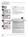
Current Output 1
Process variable. Current start. Current end.
1
2
1) Press menu key.
2) Select CONF using keys, press enter.
3) Select OUT1 menu using keys, press
enter.
4) All items of this menu group are indicated by
the “OT1:” code.
Press enter to select menu,
edit using arrow keys (see next page).
Confirm (and proceed) using enter.
5) End: Press meas key until the [meas] mode
indicator is displayed.
3
4
4
5
46
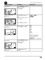
CHANNEL: Channel selection
(process variable)
OUTPUT:
LIN: linear curve
biLIN: bilinear curve
Current start
Current end
Bilinear: vertex X
Bilinear: vertex Y
Time averaging filter
Output current during error
message
Output current during HOLD
Output current for HOLD FIX
Configuration
4
Menu item
Action
Choices
Process variable
Select using keys:
Cond: Conductivity
TMP: Temperature
CALC: Calculation
Press enter to confirm.
Current start
As selected for process
variable/range
If the adjusted range is
exceeded, the device
automatically switches
to the next higher range
(Autorange)
Modify digit using
keys,
select next digit using
keys.
Press enter to confirm.
Current end
As selected for process
variable/range
If the adjusted range is
exceeded, the device
automatically switches
to the next higher range
(Autorange)
Enter value using
keys.
Press enter to confirm.
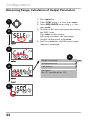
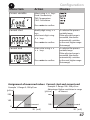
Assignment of measured values: Current start and current end
Example 1: Range 0...200 µS/cm
[µS/cm]
200
Example 2: Range 100...200 µS/cm
Advantage: Higher resolution in range
of interest
[µS/cm]
200
100
0
Output current
4
20 [mA]
100
Output current
4
20 [mA]
47
Configuration
Current Output 1
Output current curve
1
2
1) Press menu key.
2) Select CONF using keys, press enter.
3) Select OUT1 menu using keys, press
enter.
4) All items of this menu group are indicated by
the “OT1:” code.
Press enter to select menu,
edit using arrow keys (see next page).
Confirm (and proceed) using enter.
5) End: Press meas key until the [meas] mode
indicator is displayed.
3
4
4
5
48
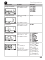
CHANNEL: Channel selection
(process variable)
OUTPUT:
LIN: linear curve
biLIN: bilinear curve
Current start
Current end
Bilinear: vertex X
Bilinear: vertex Y
Time averaging filter
Output current during error
message
Output current during HOLD
Output current for HOLD FIX
Configuration
4
Menu item
Action
Choices
Output current
curve
Select using keys.
Press enter to confirm.
LIN
Linear curve
biLIN
Bilinear curve
Current start
and current end
Enter value using
keys.
Entered value applies to
selected process variable/
range
If the adjusted range is
exceeded, the device
automatically switches
to the next higher range
(Autorange)
Press enter to confirm.
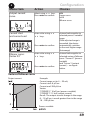
Bilinear curve:
Vertex X/Y
Enter value using
keys.
Press enter to confirm.
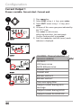
Entered value applies to
selected vertex of bilinear
curve "Corner X“ (process
variable)
and "Corner Y (output
current) – see figure
below.
Vertex of bilinear curve
Output current
Example:
Current range set to 4 ... 20 mA,
Current start: 0 µS/cm
Current end: 200 µS/cm
Vertex:
“CORNER X“: 10 µS/cm (process variable)
“CORNER Y“: 12 mA (output current)
Result: The output current change in the range
0 ... 10 µS/cm is much greater than in the range
10 ... 200 µS/cm.
Process variable
49
Configuration
Current Output 1
Adjusting time interval of output filter
1
2
1) Press menu key.
2) Select CONF using keys, press enter.
3) Select OUT1 menu using keys, press
enter.
4) All items of this menu group are indicated by
the “OT1:” code.
Press enter to select menu,
edit using arrow keys (see next page).
Confirm (and proceed) using enter.
5) End: Press meas key until the [meas] mode
indicator is displayed.
3
4
4
5
50
CHANNEL: Channel selection
(process variable)
OUTPUT:
LIN: linear curve
biLIN: bilinear curve
Current start
Current end
Bilinear: vertex X
Bilinear: vertex Y
Time averaging filter
Output current during error
message
Output current during HOLD
Output current for HOLD FIX
Configuration
4
Menu item
Action
Time averaging filter
Enter value using
keys.
Choices
Press enter to confirm.
Time averaging filter
To smoothen the current output, a low-pass filter with adjustable filter
time constant can be switched on. When there is a jump at the input
(100 %), the output level is at 63 % after the time interval has been
reached. The time interval can be set from 0 to 120 sec. If the time
interval is set to 0 sec, the current output directly follows the input.
Please note:
The filter only acts on the current output, not on the display or the
limit value!
During HOLD the filter is not applied. This prevents a jump at the
output.
Display
Time interval 0...120 s
Time interval 0...120 s
51
Configuration
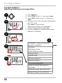
Current Output 1
Output current during Error and HOLD
1
2
1) Press menu key.
2) Select CONF using keys, press enter.
3) Select OUT1 menu using keys, press
enter.
4) All items of this menu group are indicated by
the “OT1:” code.
Press enter to select menu,
edit using arrow keys (see next page).
Confirm (and proceed) using enter.
5) End: Press meas key until the [meas] mode
indicator is displayed.
3
4
4
5
52
CHANNEL: Channel selection
(process variable)
OUTPUT:
LIN: linear curve
biLIN: bilinear curve
Current start
Current end
Bilinear: vertex X
Bilinear: vertex Y
Time averaging filter
Output current during error
message
Output current during HOLD
Output current for HOLD FIX
Configuration
4
Menu item
Action
Choices
Select ON or OFF using
Output current
during error message keys.
Press enter to confirm.
Output current
during HOLD
LAST: During HOLD the
last measured value is
maintained at the output.
FIX: During HOLD a value
(to be entered) is maintained at the output.
Select using
Press enter to confirm.
Output current for
HOLD FIX
Only with FIX selected:
Enter current which is to
flow at the output during
HOLD
Enter value using
keys.
Press enter to confirm.
Output signal during HOLD:
Output current
[mA]
Output signal for HOLD
FIX setting = 21.0 mA
Output signal for HOLD
LAST setting
21
4
HOLD active
HOLD active
53
Configuration
Current Output 2
Output current range. Process variable.
1
2
1) Press menu key.
2) Select CONF using keys, press enter.
3) Select OUT2 menu using keys, press
enter.
4) All items of this menu group are indicated by
the “OT2:” code.
Press enter to select menu,
edit using arrow keys (see next page).
Confirm (and proceed) using enter.
5) End: Press meas key until the [meas] mode
indicator is displayed.
3
4
4
5
54
CHANNEL: Channel selection
(process variable)
OUTPUT:
LIN: linear curve
biLIN: bilinear curve
Current start
Current end
Bilinear: vertex X
Bilinear: vertex Y
Time averaging filter
Output current during error
message
Output current during HOLD
Output current for HOLD FIX
Configuration
4
Menu item
Action
Process variable
Select using keys:
Cond: Conductivity
TMP: Temperature
Choices
Press enter to confirm.
.
.
.
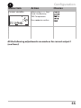
All the following adjustments are made as for current output 1
(see there)!
55
Configuration
CONTROL input
Flow measurement
1
2
1) Press menu key.
2) Select CONF using keys, press enter.
3) Select CNTR_IN menu using keys,
press enter.
4) All items of this menu group are indicated by
the “IN:” code.
Press enter to select menu,
edit using arrow keys (see next page).
Confirm (and proceed) using enter.
5) End: Press meas key until the [meas] mode
indicator is displayed.
3
4
CONTROL input
5
56
Configuration
4
Menu item
Action
Choices
Select function of
CONTROL input
Select using keys.
Press enter to confirm.
Level
Flow (for connecting a
pulse-output flow meter)
Adjust to flow meter
With "Flow" selected,
you must adjust the
device to the flow meter
used.
Enter value using arrow
keys.
Press enter to confirm.
12000 pulses/liter
In the alarm menu you can configure flow monitoring. When you have
set CONTROL to FLOW, you can specify 2 additional limit values for
maximum and minimum flow.
If the measured value lies outside this range, an alarm message and a
22-mA error signal (if configured) will be generated.
Display
Flow measurement in measuring mode
Display
Flow measurement (sensor monitor)
57
Configuration
Alarm Settings
Delay. Sensocheck.
1
2
1) Press menu key.
2) Select CONF using keys, press enter.
3) Select ALARM menu using keys, press
enter.
4) All items of this menu group are indicated by
the “ALA:” code.
Press enter to select menu,
edit using arrow keys (see next page).
Confirm (and proceed) using enter.
5) End: Press meas key until the [meas] mode
indicator is displayed.
3
4
5
ALARM: Delay
Alarm: Sensocheck
Alarm: CONTROL input
For flow monitoring:
Max. flow alarm
For flow monitoring:
Min. flow alarm
4
Error messages can be signaled by a 22 mA output current
(see Error Messages and Configuration of Output 1/Output 2).
The alarm delay time delays the color change of the display backlighting to red and the 22 mA signal (if configured).
58
Configuration
4
Menu item
Action
Delay
Enter value using
keys.
Press enter to confirm.
Sensocheck
Select Sensocheck (continuous monitoring of
sensor).
Select ON or OFF using
keys.
Press enter to confirm.
CONTROL input
The CONTROL input
can generate an alarm
depending on its assignment in the CONF menu:
FLOW (flow measurement): allows monitoring
the minimum and maximum flow (pulse counter)
LEVEL (control input):
Level monitoring.
Current input
LIMIT I-IN
Monitoring a flow meter
(4 ... 20 mA) for a limit
value, either MIN (Lo
LEVEL) or MAX (Hi LEVEL).
Press enter to confirm.
Choices
Threshold value
Hysteresis
59
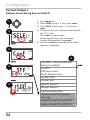
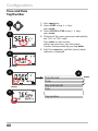
Configuration
Time and Date
Tag Number
1
2
enter
3
1) Press menu key.
2) Select CONF using keys,
press enter.
3) Select CLOCK or TAG using keys,
press enter.
4) All items of this menu group are indicated by
the “CLK:” or “TAG” code.
Press enter to select menu,
edit using arrow keys (see next page).
Confirm (and proceed) by pressing enter.
5) End: Press meas key until the [meas] mode
indicator is displayed.
enter
4
4
meas
Time format
Time
Day and month
Year
5
Tag number
60
enter
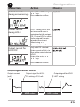
Configuration
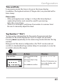
Time and Date
In measuring mode the time is shown in the lower display.
In addition, the logbook entries (cf Diagnostics) are provided with a
time stamp.
Please note:
• After prolonged power outage (> 5 days) the time display is
replaced by dashes and cannot be used for processing.
Enter the correct time.
• There is no automatic switchover from winter to summer time!
Be sure to manually adjust the time!
Tag Number (“ TAG“)
You can enter a designation for the point of measurement (tag
number) in the lower display line. Up to 32 digits are possible.
Pressing meas (repeatedly) in the measuring mode indicates the tag
number.
Being part of the device configuration, the “TAG“ can be read out
via IrDA. A standardized tag number helps, for example, to correctly
re-install a device after repair.
4
Menu item
Action
Choices
Tag number
Select character using
keys,
select next digit using
keys.
A...Z, 0...9, – + < > ? / @
Press enter to confirm.
The first 10 characters are
seen in the display without scrolling.
61
Calibration
Please note:
• All calibration procedures must be performed by trained personnel. Incorrectly set parameters may go unnoticed, but change the
measuring properties.
Each sensor is calibrated separately by entering the cell factor.
62
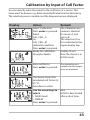
Calibration by Input of Cell Factor
You can directly enter the value for the cell factor of a sensor. This
value must be known, e.g. determined beforehand in the laboratory.
The selected process variable and the temperature are displayed.
Display
Action
Remark
Select Calibration.
Press enter to proceed.
Select
CAL_CELL_A
(or
CAL_CELL_B)
calibration method.
Press enter to proceed.
Ready for calibration.
Hourglass blinks.
The calibration procedure is identical
for sensor A and
sensor B.
The selection (A or
B) is indicated in the
upper display line.
Enter cell factor.
Press enter to proceed.
The selected process
variable and the temperature are displayed.
Display (3 sec)
Now the device is in
HOLD mode.
The device shows the
calculated cell factor (at
25 °C).
Sensoface is active.
Use the arrow keys to
select:
• MEAS (end)
• REPEAT
Press enter to proceed.
End:
HOLD is deactivated
after a short time.
63
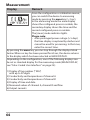
Measurement
Display
Remark
From the configuration or calibration menus,
you can switch the device to measuring
mode by pressing the meas key (> 2 sec).
In the measuring mode the main display
shows the configured process variable, the
secondary display shows the time and the
second configured process variable.
The [meas] mode indicator lights.
Please note:
• After prolonged power outage (> 5 days)
the time display is replaced by dashes and
cannot be used for processing. In that case,
enter the correct time.
By pressing the meas key you can step through the d
isplays listed
below. When no key has been pressed for 60 sec, the device returns
to the display which has been selected as MAIN DISPLAY.
Depending on the configuration, one of the following displays can
be set as standard display for the measuring mode (MAIN DISPLAY,
see “Color-Coded User Interface“ on page 25):
1)Display of tag number (“TAG“)
with up to 32 digits
2)Conductivity and temperature of channel A
3)Conductivity and temperature of channel B
4)Display of time and date
5)Measured values of channel A, channel B and flow
6)Output currents
64
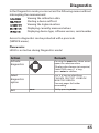
Diagnostics (DIAG)
Diagnostics
In the Diagnostics mode you can access the following menus without
interrupting the measurement:
Viewing the calibration data
Starting a device self-test
Viewing the logbook entries
Displaying currently measured values
Displaying device type, software version, serial number
Access to diagnostics can be protected with a passcode
(SERVICE menu).
Please note:
HOLD is not active during Diagnostics mode!
Action
Key
Remark
Activate
diagnostics
Pressing the menu key (down arrow)
opens the selection menu.
(Display color changes to turquoise.)
Select DIAG using keys,
press enter to confirm.
Select
diagnostics
option
Use keys to select from:
Caldata Selftest Logbook
Monitor VERSION
See next pages for further
proceeding.
Exit
meas
Exit by pressing meas.
65
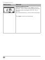
Diagnostics
Menu item
Remark
Display of calibration data
Select CALDATA using, press enter to confirm.
Use thekeys to select the desired parameter from
the bottom line of the display (LAST CAL CELL_A
CELL_B).
The selected parameter is shown in the main display.
Press meas to return to measurement.
66
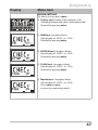
Diagnostics
Display
Menu item
Device self-test
(To abort, you can press meas.)
1) Display test: Display of all segments with
changing background colors white/green/red.
Proceed by pressing enter.
2) RAM test: Hourglass blinks,
then display of --PASS-- or --FAIL-Proceed by pressing enter.
3) EEPROM test: Hourglass blinks,
then display of --PASS-- or --FAIL-Proceed by pressing enter.
4) FLASH test: Hourglass blinks,
then display of --PASS-- or --FAIL-Proceed by pressing enter.
5) Module test: Hourglass blinks,
then display of --PASS-- or --FAIL-Press enter or meas
to return to measuring mode.
67
Diagnostics
Menu item
Remark
Display of logbook entries.
Select LOGBOOK using, press enter to confirm.
Using the keys, you can scroll backwards and
forwards through the logbook (entries -00-...-99-),
-00- being the last entry.
If the display is set to date/time, you can search for a
particular date using the keys.
Pressto view the corresponding message text.
If the display is set to the message text, you can
search for a particular message using the keys.
Pressto display the date and time.
Press meas to return to measurement.
Extended logbook / Audit Trail (via TAN)
With the keys, you can scroll backwards and
forwards through the extended logbook (entries
-000-...-199-), -000- being the last entry.
Display: CFR
Audit Trail also records function activations (CAL
CONFIG SERVICE), some Sensoface messages and
opening of the enclosure.
Display example:
Display of currently measured values
(sensor monitor):
Select MONITOR using, press enter to confirm.
Use the keys to select the desired parameter
from the bottom line of the display: R_COND_A,
R_COND_B, G_COND_A, G_COND_B
(all these apply to cell factor = 1),
RTD_A, RTD_B, TEMP_A, TEMP_B, I-INPUT (Option).
The selected parameter is shown in the main display.
Press meas to return to measurement.
68
Diagnostics
Display
Remark
Version
Here, you find the data you require for requesting a
device-specific option.
Use the keys to switch between software and
hardware version. Press enter to proceed to next
device component.
Display of device type and serial number of device.
Use the keys to switch between software and
hardware version. Press enter to proceed to next
device component.
Display of software/hardware version and
serial number for device components.
(here: measuring module)
Use the keys to switch between software and
hardware version. Press enter to proceed to next
device component.
Display of software version of HART interface.
Press enter to proceed to next device component.
69
Service (SERVICE) A
Service
In the Service mode you can access the following menus:
MONITOR
displaying currently measured values
OUT1
testing current output 1
OUT2
testing current output 2
IRDA
activating and communicating via the IrDA interface
CODES
assigning and editing passcodes
DEFAULT
resetting the device to factory settings
OPTION
enabling options via TAN.
Please note:
HOLD is active during Service mode!
Action
Key/Display
Remark
Activate
Service
Pressing the menu key (down arrow)
opens the selection menu.
Select SERVICE using keys,
press enter to confirm.
Passcode
Enter passcode “5555“ for service
mode using the keys.
Press enter to confirm.
Display
Exit
70
In service mode the following icons
are displayed:
• [diag] mode indicator
• HOLD triangle
• Service (wrench)
meas
Exit by pressing meas.
Service
Menu item
Remark
Display of currently measured values (sensor
monitor) with HOLD mode activated:
Select MONITOR using, press enter to confirm.
Select variable in the bottom text line using.
Display example:
The selected parameter is shown in the main display.
As the device is in HOLD mode, you can perform
validations using simulators without influencing the
signal outputs.
Return to Service menu: Hold meas depressed for
longer than 2 sec.
Return to measurement: Press meas once more.
Specify current at outputs 1 and 2:
Select OUT1 or OUT2 using thekeys,
press enter to confirm.
Enter a valid current value for the respective output
using keys.
Press enter to confirm.
For checking purposes, the actual output current is
shown in the bottom right corner of the display.
End by pressing enter or meas.
IrDA communication:
Select IRDA using,
press enter to confirm.
When IrDA communication is active, the device
remains in the HOLD mode for reasons of safety.
Further operation is performed via IrDA.
End communication by pressing meas.
Exception: Firmware update
(must not be interrupted!)
71
Service
Menu item
Remark
Assigning passcodes:
In the “SERVICE - CODES“ menu you can assign passcodes to DIAG, HOLD, CAL, CONF, and SERVICE modes
(Service preset to 5555).
When you have lost the Service passcode, you have
to request an “Ambulance TAN“ from the manufacturer specifying the serial number of your device.
To enter the “Ambulance TAN“, call the Service function and enter passcode 7321. After correct input of
the ambulance TAN the device signals “PASS“ for 4 sec
and resets the Service passcode to 5555.
Reset to factory settings:
In the “SERVICE - DEFAULT“ menu you can reset the
device to factory settings.
Caution!
After a reset to factory setting the device must
be reconfigured completely, including the sensor
parameters!
Option request:
Communicate the serial number and hardware/
software version of your device to the manufacturer.
These data can be viewed in the Diagnostics/Version
menu.
The “transaction number“ (TAN) you will then receive
is only valid for the device with the corresponding
serial number.
Release of options:
Options come with a “transaction number“ (TAN).
This TAN must be entered and confirmed using enter
to release the option.
72
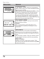
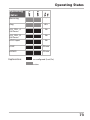
Operating states
Operating States
Operating
status
Measuring
-
Diag
60 s
CAL_CELL_A
Cell factor
No
CAL_CELL_B
Cell factor
No
HOLD input
No
CONF
20 min
SERVICE
20 min
Explanation:
as configured (Last/Fix)
active
73
74
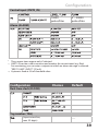
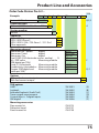
Product Line and Accessories
Order Code Stratos Pro A 2...
Example
A
2
2-wire / 4-20 mA
A
2
1
1
X
-
PH
-
1
B,C,E
Communication
Without (HART retrofittable via TAN) 0
Version number
Version
Approvals
General Safety
ATEX / IECEX Zone 2
ATEX / IECEX / FM / CSA Zone 1 / Cl 1 Div 1
Other approvals
TAN
A
1
N
B
X
Z
Measuring channel
Memosens pH / Redox
digital
Memosens Cond
digital
Memosens Oxy
digital
Dual COND (2x2-electrode sensors, analog)
N
pH / ORP value
Measuring module
(ISM digital per TAN)
Cond, 2-/4-electrode
Measuring module
Conductivity, electrodeless Measuring module
Oxygen (ISM digital and
Measuring module
traces per TAN)
MSPH
MSCOND
MSOXY
CC
PH
F
COND
CONDI
OXY
D, F
Options
Without 2nd current output
With 2nd current output
0
1
TAN options
HART
Logbook
Extended logbook (Audit Trail)
Trace oxygen measurement
Current input + 2 digital inputs
ISM digital
SW-A001
SW-A002
SW-A003
SW-A004
SW-A005
SW-A006
Mounting accessories
Pipe-mount kit
Protective hood
Panel-mount kit
ZU 0274
ZU 0737
ZU 0738
(A)
(B)
(C)
(D)
(E)
(F)
75
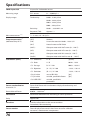
Specifications
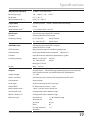
COND inputs A/B
2 inputs for 2-electrode sensors
Measuring range
2-EL sensors
0 … 30,000 µS · c
Display ranges
Conductivity
0.000 ... 9.999 µS/cm
00.00 ... 99.99 µS/cm
000.0 ... 999.9 µS/cm
0000 ... 9999 µS/cm
Resistivity
00.00 … 99.99 MΩ · cm
Response (T90)
Approx. 1 s
Measurement error 1,2,3)
< 1 % meas. val. + 0.4 µS · c
Temp compensation *)
(OFF)
Without
(reference temp 25°C)
(LIN)
Linear characteristic 00.00 ... 19.99 %/K
(NLF)
Natural waters to EN 27888
(NACL)
Ultrapure water with NaCl traces (0 ... 120 °C)
(HCL)
Ultrapure water with HCl traces (0 ... 120 °C)
Calculations (CALC)
(NH3)
Ultrapure water with NH3 traces (0... 120 °C)
(NaOH)
Ultrapure water with NaOH traces (0 ... 120 °C)
-C1- Difference
A–B
[µS/cm]
-C2- Ratio
A/B
00.00 ... 19.99
-C3- Passage
B / A * 100
000.0 ... 199.9 %
-C4- Rejection
(A – B ) / A * 100
-199.9 ... 199.9 %
-C5- Deviation
(B – A ) / A * 100
-199.9 ... 199.9 %
-C6- pH value
acc. to VBG 450
[pH]
-C7- pH value
variable, specifiable factors
[pH]
-C8- USER SPEC
variable, specifiable
parameters
Sensor standardization
channel A / B
Input of cell factor with simultaneous display of conductivity and
temperature
Permissible cell factor
0.0050 ... 1.9999 cm–1
Sensocheck
Polarization detection and monitoring of cable capacitance
Delay
Approx. 30 s
Sensoface
Provides information on the sensor condition
Sensocheck, flow monitoring
Sensor monitor
Direct display of measured values from sensor for validation
resistance / conductance / temperature
76
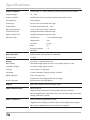
Specifications
Temperature input A/B *)
Pt1000, 2-wire connection
Measuring range
-50 ... +200 °C / –58 ... +392 °F
Resolution
0.1 °C / 0.1 °F
Measurement error 1,2,3)
0.5 K (1 K > 100 °C)
I input (TAN)
Current input 0/4 ... 20 mA / 50 Ω for flow monitoring
Characteristic
Linear
Measurement error 1.3)
< 1% current value + 0.1 mA
HOLD input
Galvanically separated (OPTO coupler)
Function
Switches device to HOLD mode
Switching voltage
0 ... 2 V (AC/DC)
HOLD inactive
10 ... 30 V (AC/DC)
HOLD active
CONTROL input
Galvanically separated (OPTO coupler),
either for LEVEL or FLOW
LEVEL function
Relay input for external monitoring equipment
FLOW function
Pulse input for flow measurement 0 ... 100 pulses/s
Function
Input for external monitoring equipment, e.g. flow
Switching voltage
000.0 ... 2 V (AC/DC)
Inactive
10 ... 30 V (AC/DC)
Active
Message via 22 mA
Display
00.0 … 99.9 l/h
Output 1
Current loop, 4 ... 20 mA, floating, protected against inverse polarity
HART communication (see further below for specifications)
Supply voltage
14 ... 30 V
Process variable *
Conductivity A/B, resistivity A/B, temperature A/B or CALC
Characteristic
linear, bilinear
Overrange *
22 mA in the case of error messages
Output filter *
PT1 filter, time constant 0 ... 120 s
Measurement error 1)
Start/end of scale
*
< 0.25 % current value + 0.025 mA
Configurable within selected range
Bilinear: Vertex X/Y *
Configurable within selected range
Minimum span
Conductivity
Temperature
1 % of selected range
10 K
pH value
0.1 pH
Ratio
0.1
Passage, rejection,
deviation
1%
77
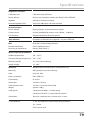
Specifications
Output 2 (Option)
Current loop 4 ... 20 mA, floating, protected against inverse polarity
Supply voltage
14 ... 30 V
Process variable *
Conductivity A/B, resistivity A/B, temperature A/B, or CALC
Characteristic
linear, bilinear
Overrange *
22 mA in the case of error messages
Output filter *
Measurement error
PT1 filter, time constant 0 ... 120 s
1)
< 0.25 % of current value + 0.05 mA
Start/end of scale *
Configurable within selected range
Bilinear: Vertex X/Y *
Configurable within selected range
Minimum span
Conductivity
1 % of selected range
Temperature
10 K
pH value
0.1 pH
Ratio
0.1
Passage, rejection,
deviation
1%
Real-time clock
Different time and date formats selectable
Power reserve
> 5 days
Display
LC display, 7-segment with icons
Main display
Character height approx. 22 mm, unit symbols approx. 14 mm
Secondary display
Character height approx. 10 mm
Text line
14 characters, 14 segments
Sensoface
3 status indicators (friendly, neutral, sad face)
Mode Indicators
meas, cal, conf, diag
Further icons for configuration and messages
Alarm indication
Display blinks, red backlighting
Keypad
Keys: meas, menu, info, 4 cursor keys, enter
HART communication
HART version 6
Digital communication by FSK modulation of output current 1
Device identification, measured values, status and messages, parameter
setting, calibration, records
FDA 21 CFR Part 11
Access control by editable passcodes
Logbook entry and flag via HART in the case of configuration changes
Message and logbook entry when enclosure is opened
78
Specifications
Diagnostics functions
Calibration data
Calibration date, cell factor
Device self-test
Display test, automatic memory test (RAM, FLASH, EEPROM)
Logbook
100 events with date and time
Extended logbook (TAN)
Audit Trail: 200 events with date and time
Service functions
Sensor monitor
Display of direct, uncorrected sensor signals
Current source
Current specifiable for output 1 and 2 (03.80 ... 22.00 mA)
IrDA interface
Infrared interface for firmware update
Data retention
Parameters, calibration data, logbook > 10 years (EEPROM)
EMC
EN 61326-1 (General Requirements)
Emitted interference
Class B (residential area)
Immunity to interference
Industry EN 61326-2-3
Nominal operating conditions
Ambient temperature
-20 ... +65 °C
Transport/Storage temperature
-30 ... +70 °C
Relative humidity
10 ... 95% not condensing
Supply voltage
14 ... 30 V
Enclosure
Molded enclosure made of glass-reinforced PBT, PC
Mounting
Wall, pipe/post or panel mounting
Color
Gray, RAL 7001
Ingress protection
IP 67, NEMA 4X
Flammability
UL 94 V-0
Dimensions
148 mm x 148 mm
Control panel cutout
138 mm x 138 mm to DIN 43 700
Weight
Approx. 1200 g
Cable glands
3 knockouts for M20 x 1.5 cable glands
2 knockouts for NPT ½” or rigid metallic conduit
Connections
Terminals, conductor cross-section max. 2.5 mm2
*) User-defined
1) Acc. to EN 60746, at nominal operating conditions
2) ± 1 count
3) Plus sensor error
79
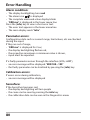
Error Handling
Alarm condition:
• The display backlighting turns red
is displayed
• The alarm icon
• The complete measured-value display blinks
• “ERR xxx“ is displayed in the lower menu line
Press the [info] key to view a short error text:
• The error text appears in the lower menu line
• The main display reads “InFo“.
Parameter errors:
Configuration data such as current range, limit values, etc are checked
during the input.
If they are out of range,
• “ERR xxx“ is displayed for 3 sec,
• the display backlighting flashes red,
• the respective maximum or minimum value is shown,
• input must be repeated.
If a faulty parameter arrives through the interface (IrDA, HART),
• an error message will be displayed: “ERR 100...199“
• the faulty parameter can be localized by pressing the [info] key
Calibration errors:
If errors occur during calibration,
• an error message will be displayed
Sensoface:
If the Sensoface becomes sad,
• the display backlighting will turn purple
• the cause can be seen by pressing the info key
• the calibration data can be seen in the Diagnostics menu
80
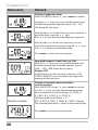
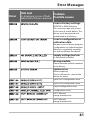
Error Messages
Error
Info text
Problem
(is displayed in case of fault
when the Info key is pressed) Possible causes
Error in factory settings
EEPROM or RAM defective
This error message only occurs
in the case of a total defect. The
device must be repaired and
recalibrated at the factory.
Error in configuration or
calibration data
Memory error in device program
Configuration or calibration data
defective; completely reconfigure and recalibrate the device.
Supply voltage too low
or no module installed
Wrong module
Please have the module replaced
at the factory.
System error
Restart required.
If error still persists, send in the
device for repair.
Span Out1 configuration error
Span Out2 configuration error
I-Input configuration error
Configuration error
OUT1 bilinear,
wrong characteristic
OUT2 bilinear,
wrong characteristic
81
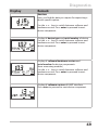
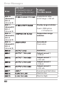
Error Messages
Info text
Error
ERR 10
(channel A)
ERR 40
(channel B)
ERR 11
(channel A)
ERR 41
(channel B)
ERR 13
(channel A)
ERR 43
(channel B)
ERR 15
(channel A)
ERR 45
(channel B)
(is displayed in case of
fault when the Info key is
pressed)
Problem
Possible causes
Conductance value
out of range: > 250 mS
Display range violation
Cond > 9999 µS/cm
< 0.1 kohm cm
Temperature range
violation
Sensocheck
Check cable
Load error
Output current 1
< 3.8 mA
Output current 1
> 20.5 mA
Output current 2
< 3.8 mA
Output current 2
> 20.5 mA
Current input limit value
Flow too low
Flow too high
82
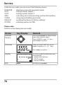
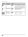
Sensoface
(Sensocheck must have been activated during configuration.)
The smiley in the display (Sensoface) alerts to sensor problems
(defective sensor, defective cable, maintenance required).
The permisible calibration ranges and the conditions for a friendly,
neutral, or sad Sensoface are summarized in the following table.
Additional icons refer to the error cause.
Sensocheck
Continuously monitors the sensor polarization and the sensor
cable capacitance. Critical values make the Sensoface “sad” and the
corresponding icon blinks:
The Sensocheck message is also output as error message Err 15.
The alarm contact is active, the display backlighting turns red, output
current 1 is set to 22 mA (when configured correspondingly).
Sensocheck can be switched off during configuration (then Sensoface
is also disabled).
Exception:
After a calibration a smiley is always displayed for confirmation.
Please note:
The worsening of a Sensoface criterion leads to the devaluation of the
Sensoface indicator (Smiley becomes “sad”). An improvement of the
Sensoface indicator can only take place after calibration or removal of
the sensor defect.
83
Sensoface
Display
Problem
Sensor defect
Temperature
Cell factor
channel A, B
84
Status
Wrong or defective sensor, significant polarization of sensor
or excessive cable capacitance
(see also error message Err 15).
Temperature outside
measuring ranges
Cell factor < 0.005 cm-1
or
cell factor > 1.9999 cm-1
FDA 21 CFR Part 11
Conformity with FDA 21 CFR Part 11
In their directive “Title 21 Code of Federal Regulations, 21 CFR Part
11, Electronic Records; Electronic Signatures“ the American health
agency FDA (Food and Drug Administration) regulates the production
and processing of electronic documents for pharmaceutical development and production. This results in requirements for measuring
devices used for corresponding applications. The following features
ensure that the measuring devices of this Series meet the demands of
FDA 21 CFR Part 11:
Electronic Signature – Passcodes
Access to the device functions is regulated and limited by individually
adjustable codes – “Passcodes“ (see SERVICE). This prevents unauthorized modification of device settings or manipulation of the measurement results. Appropriate use of these passcodes makes them suitable
as electronic signature.
Audit Trail
Every (manual) change of device settings can be automatically documented. Each change is tagged with a “Configuration Change Flag“,
which can be interrogated and documented using HART communication. Altered device settings or parameters can also be retrieved and
documented using HART communication.
Extended logbook
Audit Trail also records function activations (CAL, CONFIG, SERVICE),
some Sensoface messages (cal timer, wear) and opening of the
enclosure.
85
Index
A
Access codes 85, 92
Accessories 75
Alarm 29
Alarm and HOLD messages 30
Alarm settings 58
Ambulance TAN 72
Assembly 10
Audit Trail 85
Autorange 47
B
Backlighting 21
Bilinear curve 49
C
Calculation formulas 33
Calculation of output parameters 44
Calibration 26, 62
Calibration by input of cell factor 63
Calibration errors 80
Calibration data 66
Calibration errors 80
CD-ROM 3
Channel selection and display assignment 32
Configuration 26
Alarm 58
CONTROL input 56
Current output 1 46
Current output 2 54
Overview 31
Sensor 42
Tag number 60
Time and date 60
Connection length for sensors 32
CONTROL input 30
Configuration 56
Current input 30
Current start/end 47
86
Index
D
Date 61
Display 64
Device self-test 67
Device type, display 69
Diagnostics 26, 65
Calibration data 66
Device self-test 67
Logbook 68
Sensor monitor 68
Version 69
Dimensions 11
Display 21
Display test 67
Display backlighting 21
Disposal 2
Documentation 3
E
EEPROM test 67
Electronic Signature 85
Enclosure 11
Enclosure components 10
Entering values 23
Error handling 80
Error messages 81
Extended logbook 85
F
FDA 21 CFR Part 11 85
FLASH test 67
FLOW 57
Flow measurement 56
H
HOLD 26, 28
End 28
External activation of HOLD 29
Manual activation of HOLD 29
87
Index
Output signal during HOLD 28, 53
Output signal response 28
I
Installation 14
Intended use 7
IrDA communication 71
K
Keypad 20
L
Level 57
LIMIT I-IN 30
Logbook 68
M
Measurement 22, 64
Measurement setup 32
Measuring range 44
Menu structure 27
Message via CONTROL input 30
Message via current input 30
Module test 67
Mounting plan 11
O
Operating modes 26
Operating mode, selection 23
Operating states 73
Option request: Conditions 69
Options 72, 75
TAN 72
Order code 75
Output current curve 48
Output current, fixed value 71
Output filter 50
Output signal during HOLD 28, 53
Overview 9
88
Index
P
Package contents 3, 10
Panel mounting 13
Parameter error 80
Passcodes 85, 92
Assigning a passcode 72
pH value calculation 34
Pipe mounting 12
Point of measurement, arrangement 32
Point of measurement (TAG) 61
Product line 75
Protective hood 12
R
RAM test 67
Rating plates 15
Registered trademarks 91
Release of options 72
Reset to factory settings 72
Return of products under warranty 2
S
Safety information 7, 8
Safety instructions 3
Selection menu 23
Sensocheck 58, 82, 83
Configuration 59
Sensoface 80, 83
Sensor connection 16
Sensor monitor 68, 71
Serial number, display 69
Service 26, 70
Factory setting 72
IrDA communication 71
Passcodes 72
Releasing options 72
Sensor monitor 71
Specifying current outputs 71
89
Index
Service passcode lost 72
Signal colors 21
Software version, display 69
Specifications 76
Start-up 8
T
TAG 61
TAN options 72, 75
Entering a TAN 72
Terminal assignments 15
Terminals 8, 14, 15
Time 61
Display 64
Time averaging filter 51
Trademarks 91
U
User interface 20
W
Warranty 2
Wiring 16
Wiring examples 17
90
Trademarks
The following names are registered trademarks. For practical reasons
they are shown without trademark symbol in this manual.
Stratos®
Sensocheck®
Sensoface®
Memosens® is a registered trademark of Endress+Hauser Conducta
GmbH and Knick Elektronische Messgeräte GmbH & Co. KG.
HART® is a registered trademark of the HART Communication
Foundation.
91
Passcodes
In the SERVICE – CODES menu you can assign passcodes to protect the
access to certain functions.
Operating mode
Passcode
Service (SERVICE)
5555
Diagnostics (DIAG)
HOLD mode
Calibration (CAL)
Configuration (CONF)
Knick
Elektronische Messgeräte
GmbH & Co. KG
P.O. Box 37 04 15
D-14134 Berlin
Tel: +49 (0)30 - 801 91 - 0
Fax: +49 (0)30 - 801 91 - 200
Internet: http://www.knick.de
[email protected]
TA-212.165-KNE02
20110301
Software version: 2.x