1
1 Introduction
Experiments in modern high energy physics have a demand for higher precision and therefore feature an increasing number of readout channels of the
detectors.
For the COMPASS experiment at CERN which is a xed target spectrometer allowing beam intensities up to 2 108 particles per spill, new electronics
for digitization and a new data acquisition system is being developed which
can cope with the large data rates.
Once the new front-end electronics reach the stage of mass-production,
they will have to be tested thoroughly before being used in the experiment.
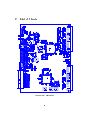
The CATCH1-module is the ideal facility for testing purposes. It features the
same communications with the front-end as those being used in the COMPASS experiment. All the data between front-end board and CATCH1 are
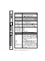
transferred via an S-UTP cable (CAT 5+): the digitized detector information (Chapters 2.2 and 2.3), initialization data for the front-end electronics
(Chapter 2.4), four USER commands (e.g. TRIGGER) for the front-end
(Chapter 2.6) and distribution of a 40 MHz clock. The main di
erence is
that the CATCH1 only communicates with one front-end board (64 channels) whereas in the experiment 16 front-end boards will be read out by one
CATCH-module.
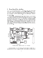
64 analog pulses
Pulser Box
1 FE-board
S-UTP (CAT 5) cable:
64 bit Pattern
Amplitude (DAC)
Data (250 MHz)
Pattern strobe
USER 1 - 4 (40 MHz)
Setup (10 MHz)
40 MHz clock
External (ECL)
CATCH 1
USER 1-4
Pattern pulse
VME bus (A32/D32)
VME :
Setup, Control & Readout
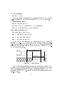
Figure 1: Possible test-setup with the CATCH1 board
3