1
by the User Command Coding Unit before being transmitted to the front-end
boards via one pair of wires on a S-UTP cable (Cat 5+).
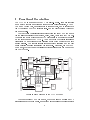
The serial transmitter provides the possibility to transfer data needed for
initialization of the front-end electronics. This serial port runs at 10 Mbit/s
and transfers 24 bit of data on a second pair of wires on the S-UTP cable
with each transmission. It cannot receive data and has no provision for error
handling.
The third wire-pair on the S-UTP cable is used to transmit the 40MHz
clock to the front-end. On the CATCH1 this clock is used by the User
Command Coding Unit and the serial transmitter. Both components send
their data synchronously to the clock.
Data generated on the front-end boards are received by the HOTLink via
the last pair of wires on the S-UTP cable. It operates at frequencies up to
330 MHz and monitors transmission errors. Having arrived on the CATCH1module the data are parallelized into words of 8 bit. The data are stored in a
FIFO bu
er from where they can be read out to the VMEbus. An additional
bit indicating transmission errors is also stored in the FIFO bu
er being nine
bit wide.
2.1 VME Interface
The VME interface of the CATCH1 consists of an address decoder and a state
machine. The address decoder monitors the VME address lines and passes
a valid command to the state machine where the corresponding actions are
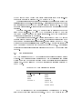
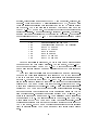
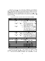
carried out. Table 1 lists the VME data transfer bus signals monitored by
the CATCH1.
Table 1: VME data transfer bus signals
Addressing Data
A31-A01 D31-D00
AM5-AM0
DS0*
DS1*
LWORD*
Control
AS*
DS0*
DS1*
WRITE*
(BERR*)
(DTACK*)
SYSRESET*
DTACK* is asserted by the module itself and the signal BERR* is foreseen but not yet implemented in the design. The CATCH1 works in the A32
6